JP7088043B2 - Motor control device - Google Patents
Motor control device Download PDFInfo
- Publication number
- JP7088043B2 JP7088043B2 JP2019008062A JP2019008062A JP7088043B2 JP 7088043 B2 JP7088043 B2 JP 7088043B2 JP 2019008062 A JP2019008062 A JP 2019008062A JP 2019008062 A JP2019008062 A JP 2019008062A JP 7088043 B2 JP7088043 B2 JP 7088043B2
- Authority
- JP
- Japan
- Prior art keywords
- motor
- rotation speed
- control
- rotation
- voltage
- Prior art date
- Legal status (The legal status is an assumption and is not a legal conclusion. Google has not performed a legal analysis and makes no representation as to the accuracy of the status listed.)
- Expired - Fee Related
Links
Images



Landscapes
- Control Of Ac Motors In General (AREA)
- Control Of Motors That Do Not Use Commutators (AREA)
Description
本発明は、モータ制御装置に関する。 The present invention relates to a motor control device.
車両のエアコン等の送風に用いられるモータは、起動時及び停止時に静粛性が求められる場合がある。例えば高速回転中に上位の制御装置から停止指令が送信されると、モータを駆動する電圧を生成する駆動回路の動作を停止させることにより、当該モータへの電力供給を停止して、当該モータを惰性回転させた後に停止させる。 Motors used for ventilation such as air conditioners of vehicles may be required to be quiet at the time of starting and stopping. For example, when a stop command is transmitted from a higher-level control device during high-speed rotation, the operation of the drive circuit that generates the voltage that drives the motor is stopped, so that the power supply to the motor is stopped and the motor is turned on. It is stopped after coasting.
しかしながら、惰性回転中のモータに対して、当該モータを再度回転させる再起動の指令が送信された場合、当該モータがハンチングを起こし、作動音が大きくなる場合があった。 However, when a restart command for rotating the motor again is transmitted to the motor during inertial rotation, the motor may hunt and the operating noise may become louder.
モータ制御装置は、一例としてPI制御(Proportional-Integral Controller:比例積分制御)により、上位制御装置から入力された指令信号が示す目標回転速度とPI制御の制御値との偏差を解消するようにして、当該モータの回転速度を目標回転速度に近付ける制御を行う。PI制御の制御値は、PI制御のソフトウェアによっては、惰性回転中のモータの実回転速度よりも時系列での低下が著しい場合があり、かかる場合には、目標回転速度とPI制御の制御値との偏差が、目標回転速度と実回転速度との偏差よりも大きくなる。その結果、再起動時のモータの回転が急加速されることになり、上記のハンチングが発生する。 As an example, the motor control device uses PI control (Proportional-Integral Controller) to eliminate the deviation between the target rotation speed indicated by the command signal input from the host control device and the control value of PI control. , Control to bring the rotation speed of the motor closer to the target rotation speed. Depending on the PI control software, the control value of PI control may decrease significantly in time series from the actual rotation speed of the motor during coasting rotation. In such a case, the control value of the target rotation speed and PI control The deviation from and is larger than the deviation between the target rotation speed and the actual rotation speed. As a result, the rotation of the motor at the time of restart is suddenly accelerated, and the above-mentioned hunting occurs.
特許文献1には、モータの回転速度が0rpmになった後に当該モータを再起動する、モータ制御装置の発明が開示されている。 Patent Document 1 discloses an invention of a motor control device that restarts a motor after the rotation speed of the motor reaches 0 rpm.
しかしながら、特許文献1に記載のモータ制御装置では、モータの回転速度が0rpmになるまで当該モータの再起動を実行しないので、制御の応答性に難があるおそれがあった。 However, in the motor control device described in Patent Document 1, since the motor is not restarted until the rotation speed of the motor reaches 0 rpm, there is a possibility that the responsiveness of the control may be difficult.
本発明は上記に鑑みてなされたもので、停止状態に移行中のモータを円滑かつ迅速に再起動できるモータ制御装置を提供することを目的とする。 The present invention has been made in view of the above, and an object of the present invention is to provide a motor control device capable of smoothly and quickly restarting a motor in a stopped state.
前記課題を解決するために、請求項1に記載のモータ制御装置は、モータの回転速度を検出する回転速度検出部と、前記モータに供給する電圧を生成する駆動回路と、回転指令が示す目標回転速度で前記モータを回転させる電圧を生成するように前記駆動回路を制御すると共に、前記モータが回転中に停止指令が入力された場合、前記駆動回路を制御して前記モータの回転を減速させ、前記回転速度検出部で検出した回転速度が第1回転速度以下になった際に、前記モータへ供給する電圧を停止するように前記駆動回路を制御して前記モータを惰性回転させ、前記モータが惰性回転中に回転指令が入力された場合に、前記回転速度検出部で検出した回転速度が前記第1回転速度よりも低く、かつ前記モータの回転が停止状態ではない第2回転速度以下になった際に、該入力された回転指令が示す目標回転速度と予め設定された制御値との偏差に基づいて決定した電圧を生成するように前記駆動回路を制御する制御部と、を含んでいる。
In order to solve the above problems, the motor control device according to claim 1 has a rotation speed detection unit that detects the rotation speed of the motor, a drive circuit that generates a voltage to be supplied to the motor, and a target indicated by a rotation command. The drive circuit is controlled so as to generate a voltage for rotating the motor at the rotation speed, and when a stop command is input while the motor is rotating, the drive circuit is controlled to decelerate the rotation of the motor. When the rotation speed detected by the rotation speed detection unit becomes equal to or lower than the first rotation speed, the drive circuit is controlled so as to stop the voltage supplied to the motor to cause the motor to coast and rotate. When a rotation command is input during coastal rotation, the rotation speed detected by the rotation speed detection unit is lower than the first rotation speed, and the rotation of the motor is equal to or less than the second rotation speed that is not in the stopped state. Includes a control unit that controls the drive circuit to generate a voltage determined based on the deviation between the target rotation speed indicated by the input rotation command and the preset control value . There is.
このモータ制御装置によれば、惰性回転して停止状態に移行するモータを再び回転させる回転指令が入力された場合に、モータの実回転速度がある程度低下し、かつ当該モータが停止する前に当該モータへの通電を行うことにより、停止状態に移行中のモータを円滑かつ迅速に再起動できる。 According to this motor control device, when a rotation command for rotating a motor that coasts and shifts to a stopped state is input, the actual rotation speed of the motor decreases to some extent, and the motor is said to be before the motor is stopped. By energizing the motor, the motor in the stopped state can be restarted smoothly and quickly.
また、このモータ制御装置によれば、目標回転速度と制御値との偏差を解消するようにモータに通電することにより、停止状態に移行中のモータを円滑に再起動できる。
Further, according to this motor control device, by energizing the motor so as to eliminate the deviation between the target rotation speed and the control value, the motor in the stopped state can be smoothly restarted.
請求項2に記載のモータ制御装置は、請求項1に記載のモータ制御装置において、前記第2回転速度は、前記第2回転速度と前記制御値との差分が、前記第1回転速度と前記制御値との差分よりも小さく、かつ所定範囲内であるように設定される。
The motor control device according to claim 2 is the motor control device according to claim 1 , wherein the second rotation speed is the difference between the second rotation speed and the control value, and the first rotation speed and the control value. It is set to be smaller than the difference from the control value and within a predetermined range.
このモータ制御装置によれば、実回転速度が、制御値と実回転速度との差分が所定範囲になる第2回転速度以下になった際に、目標回転速度と制御値との偏差に基づいてモータに供給する電圧を決定することにより、再起動時のモータの急加速を抑制して当該モータを円滑に再起動できる。 According to this motor control device, when the actual rotation speed becomes equal to or less than the second rotation speed in which the difference between the control value and the actual rotation speed is within a predetermined range, the actual rotation speed is based on the deviation between the target rotation speed and the control value. By determining the voltage to be supplied to the motor, the sudden acceleration of the motor at the time of restart can be suppressed and the motor can be restarted smoothly.
請求項3に記載のモータ制御装置は、請求項2に記載のモータ制御装置において、前記偏差に基づく電圧決定において、比例制御、比例積分制御及び比例積分微分制御のいずれかを用いる。停止状態に移行中のモータを円滑かつ迅速に再起動できる。 The motor control device according to claim 3 uses any one of proportional control, proportional integral control, and proportional integral differential control in the voltage determination based on the deviation in the motor control device according to claim 2 . The motor that is in the stopped state can be restarted smoothly and quickly.
このモータ制御装置によれば、目標回転速度と制御値との偏差を解消するようにしてモータに供給する電圧を決定する比例制御、比例積分制御及び比例積分微分制御のいずれかを用いることにより、停止状態に移行中のモータを円滑に再起動できる。 According to this motor control device, by using either proportional control, proportional integral control, or proportional integral differential control that determines the voltage supplied to the motor so as to eliminate the deviation between the target rotation speed and the control value. The motor that is in the stopped state can be restarted smoothly.
図1は、本実施の形態に係るモータ制御装置20の概略を示す図である。インバータ回路40は、三相モータであるモータ52のステータ14のコイルに供給する電力をスイッチングする。例えば、インバータFET44A、44DはU相コイル14Uに、インバータFET44B、44EはV相コイル14Vに、インバータFET44C、44FはW相コイル14Wに、各々供給する電力のスイッチングを行う。
FIG. 1 is a diagram showing an outline of a motor control device 20 according to the present embodiment. The
インバータFET44A、44B、44Cの各々のドレインは、ノイズ除去用のチョークコイル46を介して車載のバッテリ80の正極に接続されている。また、インバータFET44D、44E、44Fの各々のソースは、逆接防止FET48を介してバッテリ80の負極に接続されている。
Each drain of the
本実施の形態では、シャフト16と同軸に設けられたロータマグネット12A又はセンサマグネットの磁界をロータ12の回転位置を示す磁界としてホールセンサ12Bが検出する。マイコン32は、ホールセンサ12Bにより検出された磁界に基づいてロータ12の回転速度及び位置(回転位置)を検出し、ロータ12の回転速度及び回転位置に応じてインバータ回路40のスイッチングの制御を行う。
In the present embodiment, the
マイコン32には、エアコンのスイッチ操作に対応してエアコンを制御する、マイコン32に対する上位の制御装置であるエアコンECU82からのロータ12の回転速度に係る速度指令値を含む制御信号が入力される。また、マイコン32には、サーミスタ54Aと抵抗54Bとで構成された分圧回路54と、インバータ回路40とバッテリ80の負極との間に設けられた電流検出部56とが接続されている。
A control signal including a speed command value related to the rotation speed of the rotor 12 from the air conditioner ECU 82, which is a higher control device for the
分圧回路54を構成するサーミスタ54Aは、回路の基板の温度に応じて抵抗値が変化するので、分圧回路54が出力する信号の電圧は基板の温度に応じて変化する。マイコン32は、分圧回路54から出力される信号の電圧の変化に基づいて、基板の温度を算出する。
Since the resistance value of the
電流検出部56は、抵抗値が0.2mΩ~数Ω程度のシャント抵抗56Aと、シャント抵抗56Aの両端の電位差を増幅してシャント抵抗56Aの電流に比例する電圧値を信号として出力するアンプ56Bとを含み、アンプ56Bが出力した信号は、マイコン32の温度保護制御部62に入力される。温度保護制御部62は、アンプ56Bが出力した信号に基づいて、インバータ回路40の電流を算出する。
The
本実施の形態では、サーミスタ54Aを含む分圧回路54からの信号、電流検出部56が出力した信号、及びホールセンサ12Bが出力した信号は、マイコン32内の温度保護制御部62に入力される。温度保護制御部62は、各々入力された信号に基づいて基板の素子の温度、インバータ回路40の電流、及びロータ12の回転速度等を算出する。また、温度保護制御部62には、電源であるバッテリ80が接続されており、温度保護制御部62は、バッテリ80の電圧を電源電圧値として検知する。
In the present embodiment, the signal from the voltage dividing
エアコンECU82からの制御信号は、マイコン32内の速度制御部64に入力される。速度制御部64には、ホールセンサ12Bが出力した信号も入力される。速度制御部64は、エアコンECU82からの制御信号並びにホールセンサ12Bからの信号に基づくロータ12の回転速度及び回転位置に基づいて、インバータ回路40のスイッチングの制御に係るPWM(Pulse Width Modulation)制御のデューティ比を算出する。
The control signal from the air conditioner ECU 82 is input to the
速度制御部64が算出したデューティ比を示す信号は、PWM出力部66と温度保護制御部62とに入力される。温度保護制御部62は、基板の素子の温度と、ロータ12の回転速度と、モータ52及びモータ制御装置20の回路の負荷と、に基づいて、速度制御部64が算出したデューティ比を補正して、速度制御部64にフィードバックする。モータ及び回路の負荷は、例えば、インバータ回路40の電流、電源電圧又はインバータ回路40が生成した電圧のデューティ比である。本実施の形態では、インバータ回路40が生成した電圧のデューティ比はPWM出力部66がインバータ回路40に生成させる電圧のデューティ比と同じである。図1に示したように、PWM出力部66がインバータ回路40に生成させる電圧のデューティ比を示す信号は、温度保護制御部62にも入力されている。
The signal indicating the duty ratio calculated by the
また、温度保護制御部62には、記憶装置であるメモリ68が接続されている。メモリ68は、モータ52及び回路が過負荷状態になった場合にデューティ比を制限するための制限値等を記憶している。
Further, a
速度制御部64は、温度保護制御部62による補正を、例えばPI制御等によって自身が算出したデューティ比にフィードバックし、当該フィードバックを行ったデューティ比を示す信号をPWM出力部66に出力する。PWM出力部66は、入力された信号が示すデューティ比の電圧を生成するようにインバータ回路40のスイッチングを制御する。
The
本実施の形態では、U相コイル14U、V相コイル14V、W相コイル14Wに各々生じた誘起電圧を検出し、検出した誘起電圧に基づいて算出したロータ12の位置信号を出力する誘起電圧検出部70を備えている。
In the present embodiment, the induced voltage detection that detects the induced voltage generated in each of the
また、本実施の形態では、ホールセンサ12Bが検知したロータ12の位置信号と、誘起電圧検出部70が誘起電圧に基づいて算出したロータ12の位置信号とを比較して、ホールセンサ12Bが検出したロータ12の位置信号の補正量を算出するセンサ信号補正量算出部72を備えている。センサ信号補正量算出部72が算出した補正量は、前述の速度制御部64に入力される。速度制御部64は、ホールセンサ12Bからの信号を上述の補正量で補正して、デューティ比を算出する。補正量の算出のタイミングは、種々の場合が考えられるが、一例として、モータ52の始動直後である。又は、モータ52の回転制御中に、ホールセンサ12Bが検知したロータ12の位置信号と、誘起電圧検出部70が誘起電圧に基づいて算出したロータ12の位置信号とのずれが許容範囲を超えた場合に、当該補正量を算出してもよい。
Further, in the present embodiment, the
モータ52は三相モータ、一例としてブラシレスDCモータであるが、ブラシ付きDCモータでもよい。モータ52がブラシ付きDCモータの場合、インバータ回路40に代えて、4つのFETで構成されたHブリッジ回路でモータ52に供給する電圧を生成する。また、モータ52がブラシ付きDCモータの場合、ロータの位置の検出は不要なので、ホールセンサ12B、誘起電圧検出部70及びセンサ信号補正量算出部72は不要となる。
The
図2は、本実施の形態に係るモータ制御装置20の再起動処理の一例を示したフローチャートである。図2に示した処理では、上位制御装置であるエアコンECU82からマイコン32にモータ52を定常回転速度で回転させる指令信号が入力され、マイコン32が当該指令信号に従ってモータ52が定常回転速度で回転するようにインバータ回路40を制御していた際に、エアコンECU82からモータ52の停止指令が入力された場合を想定している。ステップ200では、停止指令が入力されたか否かを判定し、停止指令が入力された場合は手順をステップ202に移行し、停止指令が入力されていない場合は、ステップ200での停止指令の入力の判定を継続する。
FIG. 2 is a flowchart showing an example of the restart process of the motor control device 20 according to the present embodiment. In the process shown in FIG. 2, a command signal for rotating the
ステップ202では、モータ52に供給する電圧を低下させる、すなわちモータ52のコイルに印加する電圧のデューティ比を低下させてモータ52の回転速度の減速を開始する。
In
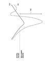
図3は、本実施の形態に係るモータ制御装置20による再起動処理におけるモータ52の回転速度の時系列での変化の一例を示した概略図である。図3に示したように、時間t1で停止指令が入力されたことにより、定常回転速度で回転していたモータ52は減速を開始する。定常回転速度は、モータ制御装置20及びモータ52等の仕様によって異なるが、本実施の形態では、一例として3000rpm~5000rpm程度である。
FIG. 3 is a schematic diagram showing an example of changes in the rotation speed of the
ステップ204では、モータ52の回転速度が惰性開始回転速度である第1回転速度以下になったか否かを判定する。第1回転速度は、モータ制御装置20及びモータ52等の仕様によって異なるが、本実施の形態では、一例として目標回転速度である定常回転速度の略1/5~2/3の回転速度であり、より具体的には1000rpm~2000rpm程度である。ステップ204でモータ52の回転速度が第1回転速度以下になった場合は手順をステップ206に移行し、モータ52の回転速度が第1回転速度を超えている場合はステップ204での判定を継続する。
In
ステップ206では、インバータFET44A、44B、44C、44D、44E、44Fのスイッチングをオフにして、モータ52へ供給する電圧の生成を停止してモータ52の惰性回転を開始する。図3に示したように、時間t2で、モータ52の回転速度が第1回転速度以下になったので、インバータ回路40からの電力供給が停止され、モータ52は惰性回転を始める。モータ52の惰性回転は後述するように実回転速度100が復帰時回転速度である第2回転速度以下になる時間t4まで継続する。本実施の形態では、時間t2~t4の区間を惰性回転区間102と呼称する。
In
ステップ208では、上位制御装置であるエアコンECU82から、モータ52を定常回転速度で回転させる回転指令が入力された否かを判定する。図3では時間t3において回転指令が入力されている。ステップ208では、時間t3のように回転指令が入力された場合は手順をステップ210に移行し、回転指令が入力されていない場合は手順をステップ216に移行する。
In
しかしながら、時間t3でのPI制御の制御値は、モータ52の実回転速度に比して大きく低下する場合がある。
However, the control value of PI control at time t 3 may be significantly lower than the actual rotation speed of the
図4は、時間t3で回転指令に応じてモータ52の回転制御を行った場合の実回転速度100とPI制御の制御値106とを比較した概略図の一例である。PI制御の制御値は、モータ52への通電が行われている場合は、基本的にホールセンサ12B等で検出したモータ52の実回転速度100であるが、停止状態に移行する惰性回転時のモータ52を再起動する際は、マイコン32の仕様によっては、実回転速度100ではなく、マイコン32に予め設定された制御値106を用いてPI制御を開始する場合がある。制御値106は、モータ52の惰性回転時に実回転速度100のように時系列で低下する傾向を示す。
FIG. 4 is an example of a schematic diagram comparing the
しかしながら、モータ52の出力軸には転がり軸受等が設けられている場合がある。かかる場合には惰性回転であっても実回転速度100は急激に低下せず、モータ52への電力供給が停止された後の時間t3においても、実回転速度100は、惰性開始回転速度である第1回転速度より若干低下した惰性回転継続回転速度に減速されるに留まることがある。
However, a rolling bearing or the like may be provided on the output shaft of the
モータ52の惰性回転時に実回転速度100の低下が緩慢であるのに対し、モータ52への電力供給が停止された場合を想定したPI制御の制御値106が、実回転速度100に比して大きく低下すると、制御値106と実回転速度100との差分108が拡大する。そして、かかる差分108が拡大した状態では、当然、回転指令が示す目標回転速度である定常回転速度と制御値106との偏差が、定常回転速度と実回転速度100との偏差よりも大きくなる。定常回転速度と実回転速度100との偏差よりも大きな偏差を解消するようにPI制御を行うと、モータ52の回転速度を必要以上に急激に加速することになり、ハンチングを発生させるおそれがある。
While the
本実施の形態では、時間t3で回転指令が入力されても、後述するように実回転速度100が復帰時回転速度である第2回転速度以下になる時間t4までモータ52の回転制御を開始せず、モータ52の惰性回転を継続する。本実施の形態では、時間t3~t4の区間を指令受信禁止区間104と呼称する。
In the present embodiment, even if the rotation command is input at the time t 3 , the rotation control of the
ステップ210では、モータ52の実回転速度100が第1回転速度よりも低速である第2回転速度以下になったか否かを判定する。
In
図5は、時間t4で回転指令に応じてモータ52の回転制御を行った場合の実回転速度100とPI制御の制御値106とを比較した概略図の一例である。図5に示したように、実回転速度100が第2回転速度に達した時間t4では、実回転速度100とPI制御の制御値106との差分110は、時間t3での差分108よりも小さくなる。
FIG. 5 is an example of a schematic diagram comparing the
本実施の形態では、図5に示した差分110が、モータ52の回転制御でハンチングを生じない所定範囲内になるような実回転速度100を、復帰時回転速度である第2回転速度に設定する。第2回転速度は、モータ制御装置20及びモータ52等の仕様によって異なるが、本実施の形態では、一例として第1回転速度の略1/8~3/4の回転速度であり、より具体的には250rpm~750rpm程度である。また、第2回転速度は、第1回転速度よりも低速であるが、いかなる場合も0rpmよりも大きな回転速度である。すなわち、第2回転速度では、モータ52の回転は停止状態ではない。
In the present embodiment, the
ステップ210で、実回転速度100が第2回転速度以下の場合は手順をステップ212に移行し、実回転速度100が第2回転速度を上回る場合はステップ214で回転指令を無視し、手順をステップ210に移行する。
In
ステップ212では、インバータ回路40のインバータFET44A、44B、44C、44D、44E、44Fのスイッチングを開始して、モータ52へ供給する電圧の生成を再開する。当該電圧(デューティ比)は、目標回転速度である定常回転速度とPI制御の制御値106との偏差に基づいてPI制御により決定する。通電再開は、図3の時間t4から行われるが、実際にモータ52の実回転速度100が増速されるまで若干の時間差がある。しかしながら、モータ52の実回転速度100が0rpmになった後にモータ52への電力供給を再開する場合よりも、応答性は良好である。
In
図3に示した破線は、モータ52の回転速度が0rpmになった際にモータ52への電力供給を再開した場合の実回転速度112である。図3に示したように時間t5で実回転速度112は0rpmになるが、時間t4でモータ52への電力供給を再開した場合、時間t5では実回転速度100は目標回転速度である定常回転速度に向けて加速している段階である。従って、本実施の形態では、モータ52の回転速度が0rpmになった際にモータ52への電力供給を再開した場合よりも、モータ52の回転再開の応答性に優れる。
The broken line shown in FIG. 3 is the
ステップ212でモータ52への電力供給を再開した後は、制御値106に代えて実回転速度100を目標回転速度である定常回転速度に近付けるように加速するPI制御が行われ、再起動処理をリターンする。
After restarting the power supply to the
ステップ208で回転指令が入力されなかった場合は、ステップ216でモータ52を停止させるか否かを判定する。ステップ216では、実回転速度100が第2回転速度以下になった場合に、モータ52の惰性回転を継続することによりモータ52を停止させて処理をリターンする。ステップ216で実回転速度100が第2回転速度を超える場合は、手順をステップ208に移行して、回転指令の入力の有無の判定をする。
If the rotation command is not input in
以上説明したように、本実施の形態に係るモータ制御装置20によれば、モータ52の実回転速度100とPI制御の制御値106との差分が許容範囲となる第2回転速度でモータ52への通電を再開することにより、再起動時のモータ52の急加速を抑制してハンチングを防止できる。その結果、停止状態に移行中のモータ52を円滑かつ迅速に再起動できるという効果を奏する。
As described above, according to the motor control device 20 according to the present embodiment, the
本変形例における上述の回転制御は、マイコン32のソフトウェアを変更することにより実現できる。従って、既存のモータ制御装置のハードウェアの構成を変更することなく、低コストでモータを円滑に再起動することができる。
The above-mentioned rotation control in this modification can be realized by changing the software of the
本実施の形態では、モータ52の回転制御においてPI制御を用いたが、PI制御のほかに、P制御(Proportional Controller:比例制御)又はPID制御(Proportional-Integral-Differential Controller:比例積分微分制御)によって実回転速度100を目標回転速度に徐々に近づけるようにしてもよい。
In this embodiment, PI control is used in the rotation control of the
本発明は、上記の形態例に限定されるものではなく、上記の形態例以外にも、その主旨を逸脱しない範囲内において種々変形して実施可能であることは勿論である。 The present invention is not limited to the above-mentioned embodiment, and it is needless to say that the present invention can be variously modified and implemented within a range not deviating from the gist thereof other than the above-mentioned embodiment.
12…ロータ、12A…ロータマグネット、12B…ホールセンサ、14…ステータ、14U…U相コイル、14V…V相コイル、14W…W相コイル、16…シャフト、20…モータ制御装置、32…マイコン、40…インバータ回路、44A,44B,44C,44D,44E,44F…インバータFET、46…チョークコイル、48…逆接防止FET、52…モータ、54…分圧回路、54A…サーミスタ、54B…抵抗、56…電流検出部、56A…シャント抵抗、56B…アンプ、62…温度保護制御部、64…速度制御部、66…PWM出力部、68…メモリ、70…誘起電圧検出部、72…センサ信号補正量算出部、80…バッテリ、82…エアコンECU、100…実回転速度、102…惰性回転区間、104…指令受信禁止区間、106…制御値、108,110…差分、112…実回転速度、t1,t2,t3,t4,t5…時間 12 ... rotor, 12A ... rotor magnet, 12B ... hall sensor, 14 ... stator, 14U ... U-phase coil, 14V ... V-phase coil, 14W ... W-phase coil, 16 ... shaft, 20 ... motor control device, 32 ... microcomputer, 40 ... Inverter circuit, 44A, 44B, 44C, 44D, 44E, 44F ... Inverter FET, 46 ... Chalk coil, 48 ... Reverse connection prevention FET, 52 ... Motor, 54 ... Voltage division circuit, 54A ... Thermista, 54B ... Resistance, 56 ... current detection unit, 56A ... shunt resistance, 56B ... amplifier, 62 ... temperature protection control unit, 64 ... speed control unit, 66 ... PWM output unit, 68 ... memory, 70 ... induced voltage detection unit, 72 ... sensor signal correction amount Calculation unit, 80 ... Battery, 82 ... Air conditioner ECU, 100 ... Actual rotation speed, 102 ... Coastal rotation section, 104 ... Command reception prohibited section, 106 ... Control value, 108, 110 ... Difference, 112 ... Actual rotation speed, t 1 , T 2 , t 3 , t 4 , t 5 ... time
Claims (3)
前記モータに供給する電圧を生成する駆動回路と、
回転指令が示す目標回転速度で前記モータを回転させる電圧を生成するように前記駆動回路を制御すると共に、前記モータが回転中に停止指令が入力された場合、前記駆動回路を制御して前記モータの回転を減速させ、前記回転速度検出部で検出した回転速度が第1回転速度以下になった際に、前記モータへ供給する電圧を停止するように前記駆動回路を制御して前記モータを惰性回転させ、前記モータが惰性回転中に回転指令が入力された場合に、前記回転速度検出部で検出した回転速度が前記第1回転速度よりも低く、かつ前記モータの回転が停止状態ではない第2回転速度以下になった際に、該入力された回転指令が示す目標回転速度と予め設定された制御値との偏差に基づいて決定した電圧を生成するように前記駆動回路を制御する制御部と、
を含むモータ制御装置。 A rotation speed detector that detects the rotation speed of the motor,
A drive circuit that generates a voltage to be supplied to the motor,
The drive circuit is controlled so as to generate a voltage for rotating the motor at the target rotation speed indicated by the rotation command, and when a stop command is input while the motor is rotating, the drive circuit is controlled to control the motor. When the rotation speed detected by the rotation speed detection unit becomes equal to or lower than the first rotation speed, the drive circuit is controlled so as to stop the voltage supplied to the motor to coast the motor. When the motor is rotated and a rotation command is input while the motor is coasting, the rotation speed detected by the rotation speed detection unit is lower than the first rotation speed, and the rotation of the motor is not in the stopped state. A control unit that controls the drive circuit to generate a voltage determined based on the deviation between the target rotation speed indicated by the input rotation command and a preset control value when the rotation speed becomes 2 or less. When,
Motor control unit including.
The motor control device according to claim 2 , wherein any of proportional control, proportional integral control, and proportional integral differential control is used in voltage determination based on the deviation.
Priority Applications (1)
| Application Number | Priority Date | Filing Date | Title |
|---|---|---|---|
| JP2019008062A JP7088043B2 (en) | 2019-01-21 | 2019-01-21 | Motor control device |
Applications Claiming Priority (1)
| Application Number | Priority Date | Filing Date | Title |
|---|---|---|---|
| JP2019008062A JP7088043B2 (en) | 2019-01-21 | 2019-01-21 | Motor control device |
Publications (2)
| Publication Number | Publication Date |
|---|---|
| JP2020120453A JP2020120453A (en) | 2020-08-06 |
| JP7088043B2 true JP7088043B2 (en) | 2022-06-21 |
Family
ID=71891441
Family Applications (1)
| Application Number | Title | Priority Date | Filing Date |
|---|---|---|---|
| JP2019008062A Expired - Fee Related JP7088043B2 (en) | 2019-01-21 | 2019-01-21 | Motor control device |
Country Status (1)
| Country | Link |
|---|---|
| JP (1) | JP7088043B2 (en) |
Families Citing this family (1)
| Publication number | Priority date | Publication date | Assignee | Title |
|---|---|---|---|---|
| KR20250055971A (en) * | 2023-10-18 | 2025-04-25 | 주식회사 엘엑스세미콘 | Apparatus for driving motor, method for controlling same, and electronic device driven by same |
Citations (3)
| Publication number | Priority date | Publication date | Assignee | Title |
|---|---|---|---|---|
| JP2009264288A (en) | 2008-04-25 | 2009-11-12 | Toyota Motor Corp | Control device of electric water pump |
| JP2013017289A (en) | 2011-07-01 | 2013-01-24 | Daikin Ind Ltd | Motor drive device, and fan control device and heat pump device using the same |
| JP2017158343A (en) | 2016-03-03 | 2017-09-07 | コニカミノルタ株式会社 | Control apparatus and control method for permanent magnet synchronous motor |
-
2019
- 2019-01-21 JP JP2019008062A patent/JP7088043B2/en not_active Expired - Fee Related
Patent Citations (3)
| Publication number | Priority date | Publication date | Assignee | Title |
|---|---|---|---|---|
| JP2009264288A (en) | 2008-04-25 | 2009-11-12 | Toyota Motor Corp | Control device of electric water pump |
| JP2013017289A (en) | 2011-07-01 | 2013-01-24 | Daikin Ind Ltd | Motor drive device, and fan control device and heat pump device using the same |
| JP2017158343A (en) | 2016-03-03 | 2017-09-07 | コニカミノルタ株式会社 | Control apparatus and control method for permanent magnet synchronous motor |
Also Published As
| Publication number | Publication date |
|---|---|
| JP2020120453A (en) | 2020-08-06 |
Similar Documents
| Publication | Publication Date | Title |
|---|---|---|
| US8159162B2 (en) | Motor control apparatus, vehicle fan drive apparatus, and motor control method | |
| JP6622249B2 (en) | Motor drive control device and motor drive control method | |
| JP2000125584A5 (en) | ||
| WO2018155332A1 (en) | Shift range control device | |
| CN109690149B (en) | Shift gear control device | |
| US8890451B2 (en) | Sensorless control unit for brushless DC motor | |
| WO2018008456A1 (en) | Electric-powered oil pump device | |
| JP2006141198A (en) | Automatic adjusting method and adjusting device for commutation angles of brushless electric motor | |
| JP2010045941A (en) | Motor control circuit, fan driver for vehicle and motor control method | |
| JP2016052203A (en) | Motor controller for vehicle air conditioner | |
| JP5724977B2 (en) | Brushless motor control system | |
| JP2017169332A (en) | Motor driving device | |
| JP7088043B2 (en) | Motor control device | |
| JP2008271698A (en) | Motor drive | |
| JP2003111469A (en) | Motor control method and control device | |
| JP6285329B2 (en) | Blower motor control device for vehicle | |
| JP3084941B2 (en) | Control drive of electric compressor for automobile | |
| JP2020018151A (en) | Motor controller | |
| JP2020072523A (en) | Motor controller | |
| JP2020188552A (en) | Motor control device and motor control method | |
| JP2006136064A (en) | Synchronous motor control device | |
| CN110798100B (en) | Electric motor drive device and electric pump device | |
| JP4791319B2 (en) | Inverter device, compressor drive device and refrigeration / air-conditioning device | |
| WO2012093677A1 (en) | Electric pump device | |
| JP5724353B2 (en) | Brushless motor control device for electric pump |
Legal Events
| Date | Code | Title | Description |
|---|---|---|---|
| A621 | Written request for application examination |
Free format text: JAPANESE INTERMEDIATE CODE: A621 Effective date: 20210203 |
|
| A977 | Report on retrieval |
Free format text: JAPANESE INTERMEDIATE CODE: A971007 Effective date: 20211027 |
|
| A131 | Notification of reasons for refusal |
Free format text: JAPANESE INTERMEDIATE CODE: A131 Effective date: 20211130 |
|
| A521 | Request for written amendment filed |
Free format text: JAPANESE INTERMEDIATE CODE: A523 Effective date: 20220124 |
|
| TRDD | Decision of grant or rejection written | ||
| A01 | Written decision to grant a patent or to grant a registration (utility model) |
Free format text: JAPANESE INTERMEDIATE CODE: A01 Effective date: 20220510 |
|
| A61 | First payment of annual fees (during grant procedure) |
Free format text: JAPANESE INTERMEDIATE CODE: A61 Effective date: 20220523 |
|
| R151 | Written notification of patent or utility model registration |
Ref document number: 7088043 Country of ref document: JP Free format text: JAPANESE INTERMEDIATE CODE: R151 |
|
| LAPS | Cancellation because of no payment of annual fees |