JP7098043B2 - A method for producing iron sulfide, a positive electrode for a lithium secondary battery containing iron sulfide produced from the method, and a lithium secondary battery provided with the positive electrode. - Google Patents
A method for producing iron sulfide, a positive electrode for a lithium secondary battery containing iron sulfide produced from the method, and a lithium secondary battery provided with the positive electrode. Download PDFInfo
- Publication number
- JP7098043B2 JP7098043B2 JP2021500722A JP2021500722A JP7098043B2 JP 7098043 B2 JP7098043 B2 JP 7098043B2 JP 2021500722 A JP2021500722 A JP 2021500722A JP 2021500722 A JP2021500722 A JP 2021500722A JP 7098043 B2 JP7098043 B2 JP 7098043B2
- Authority
- JP
- Japan
- Prior art keywords
- positive electrode
- iron sulfide
- lithium secondary
- secondary battery
- sulfur
- Prior art date
- Legal status (The legal status is an assumption and is not a legal conclusion. Google has not performed a legal analysis and makes no representation as to the accuracy of the status listed.)
- Active
Links
Images


Classifications
-
- H—ELECTRICITY
- H01—ELECTRIC ELEMENTS
- H01M—PROCESSES OR MEANS, e.g. BATTERIES, FOR THE DIRECT CONVERSION OF CHEMICAL ENERGY INTO ELECTRICAL ENERGY
- H01M4/00—Electrodes
- H01M4/02—Electrodes composed of, or comprising, active material
- H01M4/62—Selection of inactive substances as ingredients for active masses, e.g. binders, fillers
- H01M4/628—Inhibitors, e.g. gassing inhibitors, corrosion inhibitors
-
- H—ELECTRICITY
- H01—ELECTRIC ELEMENTS
- H01M—PROCESSES OR MEANS, e.g. BATTERIES, FOR THE DIRECT CONVERSION OF CHEMICAL ENERGY INTO ELECTRICAL ENERGY
- H01M4/00—Electrodes
- H01M4/02—Electrodes composed of, or comprising, active material
- H01M4/36—Selection of substances as active materials, active masses, active liquids
- H01M4/58—Selection of substances as active materials, active masses, active liquids of inorganic compounds other than oxides or hydroxides, e.g. sulfides, selenides, tellurides, halogenides or LiCoFy; of polyanionic structures, e.g. phosphates, silicates or borates
- H01M4/581—Chalcogenides or intercalation compounds thereof
- H01M4/5815—Sulfides
-
- C—CHEMISTRY; METALLURGY
- C01—INORGANIC CHEMISTRY
- C01G—COMPOUNDS CONTAINING METALS NOT COVERED BY SUBCLASSES C01D OR C01F
- C01G49/00—Compounds of iron
- C01G49/12—Sulfides
-
- H—ELECTRICITY
- H01—ELECTRIC ELEMENTS
- H01M—PROCESSES OR MEANS, e.g. BATTERIES, FOR THE DIRECT CONVERSION OF CHEMICAL ENERGY INTO ELECTRICAL ENERGY
- H01M10/00—Secondary cells; Manufacture thereof
- H01M10/05—Accumulators with non-aqueous electrolyte
- H01M10/052—Li-accumulators
- H01M10/0525—Rocking-chair batteries, i.e. batteries with lithium insertion or intercalation in both electrodes; Lithium-ion batteries
-
- H—ELECTRICITY
- H01—ELECTRIC ELEMENTS
- H01M—PROCESSES OR MEANS, e.g. BATTERIES, FOR THE DIRECT CONVERSION OF CHEMICAL ENERGY INTO ELECTRICAL ENERGY
- H01M4/00—Electrodes
- H01M4/02—Electrodes composed of, or comprising, active material
- H01M4/13—Electrodes for accumulators with non-aqueous electrolyte, e.g. for lithium-accumulators; Processes of manufacture thereof
-
- H—ELECTRICITY
- H01—ELECTRIC ELEMENTS
- H01M—PROCESSES OR MEANS, e.g. BATTERIES, FOR THE DIRECT CONVERSION OF CHEMICAL ENERGY INTO ELECTRICAL ENERGY
- H01M4/00—Electrodes
- H01M4/02—Electrodes composed of, or comprising, active material
- H01M4/36—Selection of substances as active materials, active masses, active liquids
- H01M4/362—Composites
- H01M4/364—Composites as mixtures
-
- H—ELECTRICITY
- H01—ELECTRIC ELEMENTS
- H01M—PROCESSES OR MEANS, e.g. BATTERIES, FOR THE DIRECT CONVERSION OF CHEMICAL ENERGY INTO ELECTRICAL ENERGY
- H01M4/00—Electrodes
- H01M4/02—Electrodes composed of, or comprising, active material
- H01M4/36—Selection of substances as active materials, active masses, active liquids
- H01M4/38—Selection of substances as active materials, active masses, active liquids of elements or alloys
-
- H—ELECTRICITY
- H01—ELECTRIC ELEMENTS
- H01M—PROCESSES OR MEANS, e.g. BATTERIES, FOR THE DIRECT CONVERSION OF CHEMICAL ENERGY INTO ELECTRICAL ENERGY
- H01M4/00—Electrodes
- H01M4/02—Electrodes composed of, or comprising, active material
- H01M4/36—Selection of substances as active materials, active masses, active liquids
- H01M4/58—Selection of substances as active materials, active masses, active liquids of inorganic compounds other than oxides or hydroxides, e.g. sulfides, selenides, tellurides, halogenides or LiCoFy; of polyanionic structures, e.g. phosphates, silicates or borates
- H01M4/583—Carbonaceous material, e.g. graphite-intercalation compounds or CFx
- H01M4/587—Carbonaceous material, e.g. graphite-intercalation compounds or CFx for inserting or intercalating light metals
-
- C—CHEMISTRY; METALLURGY
- C01—INORGANIC CHEMISTRY
- C01P—INDEXING SCHEME RELATING TO STRUCTURAL AND PHYSICAL ASPECTS OF SOLID INORGANIC COMPOUNDS
- C01P2002/00—Crystal-structural characteristics
- C01P2002/70—Crystal-structural characteristics defined by measured X-ray, neutron or electron diffraction data
- C01P2002/72—Crystal-structural characteristics defined by measured X-ray, neutron or electron diffraction data by d-values or two theta-values, e.g. as X-ray diagram
-
- C—CHEMISTRY; METALLURGY
- C01—INORGANIC CHEMISTRY
- C01P—INDEXING SCHEME RELATING TO STRUCTURAL AND PHYSICAL ASPECTS OF SOLID INORGANIC COMPOUNDS
- C01P2002/00—Crystal-structural characteristics
- C01P2002/70—Crystal-structural characteristics defined by measured X-ray, neutron or electron diffraction data
- C01P2002/74—Crystal-structural characteristics defined by measured X-ray, neutron or electron diffraction data by peak-intensities or a ratio thereof only
-
- C—CHEMISTRY; METALLURGY
- C01—INORGANIC CHEMISTRY
- C01P—INDEXING SCHEME RELATING TO STRUCTURAL AND PHYSICAL ASPECTS OF SOLID INORGANIC COMPOUNDS
- C01P2004/00—Particle morphology
- C01P2004/01—Particle morphology depicted by an image
- C01P2004/03—Particle morphology depicted by an image obtained by SEM
-
- C—CHEMISTRY; METALLURGY
- C01—INORGANIC CHEMISTRY
- C01P—INDEXING SCHEME RELATING TO STRUCTURAL AND PHYSICAL ASPECTS OF SOLID INORGANIC COMPOUNDS
- C01P2004/00—Particle morphology
- C01P2004/60—Particles characterised by their size
- C01P2004/61—Micrometer sized, i.e. from 1-100 micrometer
-
- C—CHEMISTRY; METALLURGY
- C01—INORGANIC CHEMISTRY
- C01P—INDEXING SCHEME RELATING TO STRUCTURAL AND PHYSICAL ASPECTS OF SOLID INORGANIC COMPOUNDS
- C01P2004/00—Particle morphology
- C01P2004/60—Particles characterised by their size
- C01P2004/62—Submicrometer sized, i.e. from 0.1-1 micrometer
-
- C—CHEMISTRY; METALLURGY
- C01—INORGANIC CHEMISTRY
- C01P—INDEXING SCHEME RELATING TO STRUCTURAL AND PHYSICAL ASPECTS OF SOLID INORGANIC COMPOUNDS
- C01P2006/00—Physical properties of inorganic compounds
- C01P2006/40—Electric properties
-
- H—ELECTRICITY
- H01—ELECTRIC ELEMENTS
- H01M—PROCESSES OR MEANS, e.g. BATTERIES, FOR THE DIRECT CONVERSION OF CHEMICAL ENERGY INTO ELECTRICAL ENERGY
- H01M10/00—Secondary cells; Manufacture thereof
- H01M10/05—Accumulators with non-aqueous electrolyte
- H01M10/052—Li-accumulators
-
- H—ELECTRICITY
- H01—ELECTRIC ELEMENTS
- H01M—PROCESSES OR MEANS, e.g. BATTERIES, FOR THE DIRECT CONVERSION OF CHEMICAL ENERGY INTO ELECTRICAL ENERGY
- H01M4/00—Electrodes
- H01M4/02—Electrodes composed of, or comprising, active material
- H01M2004/021—Physical characteristics, e.g. porosity, surface area
-
- H—ELECTRICITY
- H01—ELECTRIC ELEMENTS
- H01M—PROCESSES OR MEANS, e.g. BATTERIES, FOR THE DIRECT CONVERSION OF CHEMICAL ENERGY INTO ELECTRICAL ENERGY
- H01M4/00—Electrodes
- H01M4/02—Electrodes composed of, or comprising, active material
- H01M2004/026—Electrodes composed of, or comprising, active material characterised by the polarity
- H01M2004/028—Positive electrodes
-
- Y—GENERAL TAGGING OF NEW TECHNOLOGICAL DEVELOPMENTS; GENERAL TAGGING OF CROSS-SECTIONAL TECHNOLOGIES SPANNING OVER SEVERAL SECTIONS OF THE IPC; TECHNICAL SUBJECTS COVERED BY FORMER USPC CROSS-REFERENCE ART COLLECTIONS [XRACs] AND DIGESTS
- Y02—TECHNOLOGIES OR APPLICATIONS FOR MITIGATION OR ADAPTATION AGAINST CLIMATE CHANGE
- Y02E—REDUCTION OF GREENHOUSE GAS [GHG] EMISSIONS, RELATED TO ENERGY GENERATION, TRANSMISSION OR DISTRIBUTION
- Y02E60/00—Enabling technologies; Technologies with a potential or indirect contribution to GHG emissions mitigation
- Y02E60/10—Energy storage using batteries
Landscapes
- Chemical & Material Sciences (AREA)
- Chemical Kinetics & Catalysis (AREA)
- Electrochemistry (AREA)
- General Chemical & Material Sciences (AREA)
- Inorganic Chemistry (AREA)
- Organic Chemistry (AREA)
- Engineering & Computer Science (AREA)
- Composite Materials (AREA)
- Materials Engineering (AREA)
- Manufacturing & Machinery (AREA)
- Battery Electrode And Active Subsutance (AREA)
- Inorganic Compounds Of Heavy Metals (AREA)
Description
本出願は、2018年9月18日付韓国特許出願第10‐2018‐0111788号及び2019年9月18日付韓国特許出願第10‐2019‐0114771号、そして2018年9月18日付韓国特許出願第10‐2018‐0111792号及び2019年9月18日付韓国特許出願第10‐2019‐0114782号に基づく優先権の利益を主張し、該当韓国特許出願の文献に開示されている全ての内容は本明細書の一部として含まれる。 This application is for Korean Patent Application No. 10-2018-0111788 dated September 18, 2018, Korean Patent Application No. 10-2019-0114771 dated September 18, 2019, and Korean Patent Application No. 10 dated September 18, 2018. All the content disclosed in the literature of the relevant Korean patent application, claiming the benefit of priority under -2018-0111792 and Korean Patent Application No. 10-2019-0114782 dated September 18, 2019, is herein. Included as part of.
本発明は、硫化鉄の製造方法、これより製造された硫化鉄を含むリチウム二次電池用正極及びこれを備えたリチウム二次電池に係り、より詳しくは、簡素な工程によって選択的であり高純度の硫化鉄を製造することができ、リチウム二次電池の正極添加剤で適用可能な硫化鉄(FeS2)の製造方法、そして、これより製造された硫化鉄(FeS2)がリチウム二次電池の充放電過程で生成されるリチウムポリスルフィドを吸着して電池の充放電効率を増加させ、寿命特性を向上させることができる硫化鉄(FeS2)を含むリチウム二次電池用正極及びこれを備えたリチウム二次電池に関する。 The present invention relates to a method for producing iron sulfide, a positive electrode for a lithium secondary battery containing iron sulfide produced from the method, and a lithium secondary battery provided with the same, and more specifically, the present invention is selective and high by a simple process. A method for producing iron sulfide (FeS 2 ) capable of producing pure iron sulfide and applicable as a positive electrode additive for a lithium secondary battery, and iron sulfide (FeS 2 ) produced from this method are lithium secondary. A positive electrode for a lithium secondary battery containing iron sulfide (FeS 2 ) capable of adsorbing lithium polysulfide generated in the battery charge / discharge process to increase the charge / discharge efficiency of the battery and improve the life characteristics, and the like. Regarding lithium secondary batteries.
二次電池は1回のみ放電可能な一次電池と違って、持続的に充電及び放電可能な電気貯蔵器具であって、1990年代以後携帯用電子機器の重要部品として位置づけられた。特に、リチウム二次電池は1992年日本ソニー(Sony)社によって常用化された以来、スマートフォン、デジカメ、ノートパソコンなどのような携帯用電子機器の核心部品として情報化時代をリードしてきた。 Unlike a primary battery that can be discharged only once, a secondary battery is an electric storage device that can be continuously charged and discharged, and has been positioned as an important component of portable electronic devices since the 1990s. In particular, since lithium secondary batteries were made regular use by Sony Corporation in 1992, they have led the information era as core components of portable electronic devices such as smartphones, digital cameras, and notebook computers.
近年、リチウム二次電池はその活用領域をさらに広げながら清掃機、電動工具の電源と電気自転車、電気スクーターのような分野に使われる中型電池から、電気自動車(electric vehicle;EV)、ハイブリッド電気自動車(hybrid electric vehicle;HEV)、プラグ‐インハイブリッド電気自動車(Plug‐in hybrid electric vehicle;PHEV)、各種ロボット及び大型電力貯蔵装置(Electric Storage System;ESS)のような分野に使われる大容量電池に至るまで速い速度で需要を増やしている。 In recent years, lithium secondary batteries have expanded their application areas from medium-sized batteries used in fields such as vacuum cleaners, power supplies for electric tools, electric bicycles, and electric scooters, to electric vehicles (EVs), and hybrid electric vehicles. (HYBRID ELECTRIC VEHILE; HEV), Plug-in hybrid electric vehicle (PHEV), various robots and large capacity batteries used in large power storage devices (ESS). Demand is increasing at a high speed.
しかし、現在まで出ている二次電池の中で最も優れる特性を有するリチウム二次電池も電気自動車、PHEVのような輸送器具に活発に利用されるためには幾つかの問題点があり、その中で最大の問題点は容量の限界である。 However, lithium secondary batteries, which have the best characteristics among the secondary batteries available to date, also have some problems in order to be actively used in transportation equipment such as electric vehicles and PHEVs. The biggest problem is the capacity limit.
リチウム二次電池は基本的に正極、電解質、負極などのような素材で構成され、その中で正極及び負極素材が電池の容量(capacity)を決めるので、リチウム二次電池は正極と負極の物質的な限界によって容量に制約を受ける。特に、電気自動車、PHEVのような用途に使われる二次電池は、一回充電した後、最大限に長く使用しなければならないので、その放電容量が非常に重要視される。 A lithium secondary battery is basically composed of materials such as a positive electrode, an electrolyte, and a negative electrode, and the positive electrode and negative electrode materials determine the capacity of the battery, so that the lithium secondary battery is a material for the positive electrode and the negative electrode. Capacity is limited by the limit. In particular, secondary batteries used in applications such as electric vehicles and PHEVs must be used for the maximum length of time after being charged once, so their discharge capacity is very important.
このようなリチウム二次電池の容量の限界は、多くの努力にもかかわらずリチウム二次電池の構造及び材料の制約によって完全なる解決が難しい実情である。よって、リチウム二次電池の容量問題を根本的に解決するためには、既存の二次電池の概念を飛び越える新概念の二次電池の開発が要求される。 Despite much effort, the capacity limit of such a lithium secondary battery is difficult to completely solve due to the restrictions of the structure and material of the lithium secondary battery. Therefore, in order to fundamentally solve the capacity problem of lithium secondary batteries, it is necessary to develop a new concept secondary battery that goes beyond the existing concept of secondary batteries.
リチウム‐硫黄二次電池は既存のリチウム二次電池の基本原理であるリチウムイオンの層状構造金属酸化物及び黒鉛への挿入/脱離(intercalation)反応によって決まる容量の限界を超え、転移金属の代替及び費用節減などの効果をもたらす新しい高容量、安価電池システムである。 Lithium-sulfur secondary batteries exceed the capacity limit determined by the insertion / desorption (intercation) reaction of lithium ions into layered metal oxides and graphite, which is the basic principle of existing lithium secondary batteries, and replace transition metals. It is a new high-capacity, low-cost battery system that brings about effects such as cost reduction.
リチウム‐硫黄二次電池は、正極でリチウムイオンと硫黄の変換(conversion)反応(S8+16Li++16e‐→8Li2S)から出る理論容量が1,675mAh/gに至って、負極はリチウム金属(理論容量:3,860mAh/g)を使って電池システムの超高容量化が可能である。また、放電電圧は約2.2Vなので理論的に正極、負極活物質の量を基準にして2,600Wh/kgのエネルギー密度を示す。これは層状構造の金属酸化物及び黒鉛を使用する常用リチウム二次電池(LiCoO2/graphite)の理論的エネルギー密度の400Wh/kgよりも6倍ないし7倍ほど高い数値である。 Lithium-sulfur secondary batteries have a theoretical capacity of 1,675 mAh / g from the conversion reaction (S 8 + 16Li + + 16e- → 8Li 2S) between lithium ions and sulfur at the positive electrode, and the negative electrode is a lithium metal (lithium metal (S 8 + 16Li + + 16e- → 8Li 2S). The theoretical capacity: 3,860 mAh / g) can be used to increase the capacity of the battery system. Further, since the discharge voltage is about 2.2 V, the energy density of 2,600 Wh / kg is theoretically shown based on the amounts of the positive electrode and negative electrode active materials. This is 6 to 7 times higher than the theoretical energy density of 400 Wh / kg of a conventional lithium secondary battery (LiCoO 2 / graphite) using a layered metal oxide and graphite.
リチウム‐硫黄二次電池は、2010年頃ナノ複合体を形成することで電池性能が画期的に改善できることが知られた以来、新しい高容量で、環境にやさしい、低価のリチウム二次電池で注目されていて、現在次世代電池システムとして世界中で集中的に研究されている。 Lithium-sulfur secondary batteries are new high-capacity, environmentally friendly, low-priced lithium secondary batteries since it was known around 2010 that the battery performance could be dramatically improved by forming nanocomposites. It is attracting attention and is currently being intensively researched around the world as a next-generation battery system.
現在まで明らかになったリチウム‐硫黄二次電池の主な問題点の一つは、硫黄の電気伝導度が5.0×10‐14S/cmほどで不導体に近いため電極で電気化学反応が容易ではなく、非常に大きい過電圧によって実際の放電容量及び電圧が理論にずっと及ばないという点である。初期研究者らは硫黄とカーボンの機械的ボールミーリングやカーボンを利用した表面コーティングのような方法で性能を改善しようとしたが、さほど実効はなかった。 One of the main problems of the lithium-sulfur secondary battery that has been clarified so far is that the electric conductivity of sulfur is about 5.0 × 10⁻¹⁴ S / cm, which is close to a non-conductor, so an electrochemical reaction occurs at the electrodes. It is not easy, and the actual discharge capacity and voltage are far below the theory due to the very large overvoltage. Early researchers tried to improve performance by methods such as mechanical ball milling of sulfur and carbon and surface coating with carbon, but they were not very effective.
電気伝導度によって電気化学反応が制限される問題を効果的に解決するためには、他の正極活物質一つのLiFePO4の例のように(電気伝導度:10‐9ないし10‐10S/cm)粒子の大きさを数十ナノメートル以下の大きさに減らして伝導性物質で表面処理する必要があるが、このために様々な化学的(ナノサイズの多孔性炭素ナノ構造体或いは金属酸化物構造体へのmelt impregnation)、物理的方法(high energy ball milling)などが報告されている。 In order to effectively solve the problem that the electrochemical reaction is limited by the electric conductivity, as in the example of LiFePO 4 which is one of the other positive electrode active materials (electrical conductivity: 10-9 to 10-10 S / It is necessary to reduce the size of the cm) particles to a size of several tens of nanometers or less and surface-treat them with a conductive material, which is why various chemical (nano-sized porous carbon nanostructures or metal oxidation) are required. (Melt imregulation) to a physical structure, a physical method (high electricity ball milling), and the like have been reported.
もう一つのリチウム‐硫黄電池と係る主な問題点は、放電中に生成される硫黄の中間生成体であるリチウムポリスルフィド(lithium polysulfide)の電解質への溶解である。放電が進められるにつれ、硫黄(S8)はリチウムイオンと連続的に反応してS8→Li2S8→(Li2S6)→Li2S4→Li2S2→Li2Sなど、その相(phase)が連続的に変わるようになるが、その中で硫黄が長く並んだチェーン形態のLi2S8、Li2S4(リチウムポリスルフィド)などは、リチウムイオン電池で使われる一般的な電解質で容易に溶解される性質がある。このような反応が発生すれば可逆正極容量が大きく減るだけでなく、溶解されたリチウムポリスルフィドが負極へ拡散されて様々な副反応(side reaction)を起こすようになる。 Another major problem with lithium-sulfur batteries is the dissolution of lithium polysulfide, an intermediate product of sulfur produced during discharge, into the electrolyte. As the discharge progresses, sulfur (S 8 ) reacts continuously with lithium ions to S 8 → Li 2 S 8 → (Li 2 S 6 ) → Li 2 S 4 → Li 2 S 2 → Li 2 S, etc. , The phase changes continuously, but among them, the chain form Li 2 S 8 and Li 2 S 4 (lithium polysulfide) in which sulfur is lined up for a long time are generally used in lithium ion batteries. It has the property of being easily dissolved by a typical electrolyte. If such a reaction occurs, not only the reversible positive electrode capacity is greatly reduced, but also the dissolved lithium polysulfide is diffused to the negative electrode to cause various side reactions.
リチウムポリスルフィドは特に充電過程中にシャトル反応(shuttle reaction)を起こし、これによって充電容量がずっと増加して充放電効率が急激に低下する。最近、このような問題を解決するために様々な方法が提示されているが、大きく電解質を改善する方法、負極の表面を改善する方法、正極の特性を改善する方法などに分けることができる。 Lithium polysulfide causes a shuttle reaction, especially during the charging process, which significantly increases the charging capacity and sharply reduces the charge / discharge efficiency. Recently, various methods have been proposed to solve such a problem, and they can be broadly divided into a method of improving the electrolyte, a method of improving the surface of the negative electrode, a method of improving the characteristics of the positive electrode, and the like.
電解質を改善する方法は、新規組成の機能性液体電解質、高分子電解質、イオン性液体(ionic liquid)など新しい電解質を使用してポリスルフィドの電解質への溶解を抑制したり、粘度などを調節することで負極への分散速度を制御してシャトル反応を最大限に抑制する方法である。 The method of improving the electrolyte is to suppress the dissolution of polysulfide in the electrolyte or adjust the viscosity by using a new electrolyte such as a functional liquid electrolyte with a new composition, a polymer electrolyte, or an ionic liquid. This is a method of controlling the dispersion rate to the negative electrode to maximize the shuttle reaction.
負極表面に形成されるSEIの特性を改善してシャトル反応を制御する研究が活発に行われているが、代表的にLiNO3のような電解質添加剤を投入してリチウム負極の表面にLixNOy、LixSOyなどの酸化膜を形成して改善する方法、リチウム金属の表面に厚い機能型SEI(solid‐electrolyte interphase)層を形成する方法などがある。 Research is being actively conducted to improve the characteristics of SEI formed on the surface of the negative electrode to control the shuttle reaction. Typically, an electrolyte additive such as LiNO 3 is added to the surface of the lithium negative electrode to Li x . There are a method of forming and improving an oxide film such as NO y and Li x S O y , and a method of forming a thick functional SEI (solid-electrolyte interphase) layer on the surface of a lithium metal.
最後に、正極の特性を改善する方法は、ポリスルフィドの溶解を防ぐことができるように正極粒子の表面にコーティング層を形成したり、溶解されたポリスルフィドを取ることができる多孔性物質を添加する方法などがあるが、代表的に伝導性高分子で硫黄粒子が入っている正極構造体の表面をコーティングする方法、リチウムイオンが伝導される金属酸化物で正極構造体の表面をコーティングする方法、リチウムポリスルフィドを多量吸収することができる比表面積が広くて気孔が大きい多孔性金属酸化物を正極に添加する方法、炭素構造体の表面にリチウムポリスルフィドを吸着することができる作用基(functional group)を付着する方法、グラフェンあるいはグラフェンオキシドなどを利用して硫黄粒子を包む方法などが提示された。 Finally, a method for improving the properties of the positive electrode is to form a coating layer on the surface of the positive electrode particles so as to prevent the dissolution of the polysulfide, or to add a porous substance capable of removing the dissolved polysulfide. However, typically, a method of coating the surface of a positive electrode structure containing sulfur particles with a conductive polymer, a method of coating the surface of a positive electrode structure with a metal oxide carrying lithium ions, and lithium. A method of adding a porous metal oxide having a large specific surface area and large pores capable of absorbing a large amount of polysulfide to a positive electrode, and a functional group capable of adsorbing lithium polysulfide is attached to the surface of a carbon structure. A method of wrapping sulfur particles using graphene or graphene oxide was presented.
このように努力してはいるが、このような方法はやや複雑なだけでなく活物質の硫黄を入れる量が制限されるという問題がある。よって、このような問題を複合的に解決し、リチウム‐硫黄電池の性能を改善するための新しい技術の開発が必要な実情である。 Despite these efforts, such a method is not only somewhat complicated, but also has the problem that the amount of sulfur contained in the active material is limited. Therefore, it is necessary to develop a new technique for solving such problems in a complex manner and improving the performance of the lithium-sulfur battery.
上述した問題点を解決するために、リチウム二次電池の正極添加剤と係って多角的に研究した結果、鉄前駆体と硫黄前駆体を混合してこれを熱処理し、熱処理温度と工程時間を制御して選択的に高純度の硫化鉄を製造することができることを確認した。 As a result of multifaceted research in relation to the positive electrode additive of the lithium secondary battery in order to solve the above-mentioned problems, an iron precursor and a sulfur precursor were mixed and heat-treated, and the heat treatment temperature and process time were obtained. It was confirmed that high-purity iron sulfide can be selectively produced by controlling the above.
よって、本発明は簡素な工程を通じて高純度のリチウム二次電池の正極添加剤である硫化鉄の製造方法を提供することを目的とする。 Therefore, an object of the present invention is to provide a method for producing iron sulfide, which is a positive electrode additive for a high-purity lithium secondary battery, through a simple process.
また、リチウム二次電池の正極側で発生するリチウムポリスルフィド湧出の問題を解消し、電解液との副反応を抑制するために、リチウム二次電池の正極に前記製造方法によって製造された硫化鉄(FeS2)を導入した結果、前記問題を解決してリチウム二次電池の電池性能を向上させることができることを確認して本発明を完成した。 Further, in order to solve the problem of lithium polysulfide spouting generated on the positive electrode side of the lithium secondary battery and suppress side reactions with the electrolytic solution, iron sulfide produced by the above-mentioned production method on the positive electrode of the lithium secondary battery ( As a result of introducing FeS 2 ), it was confirmed that the above-mentioned problems could be solved and the battery performance of the lithium secondary battery could be improved, and the present invention was completed.
よって、本発明の別の目的は、リチウムポリスルフィドによる問題を解消することができるリチウム二次電池用正極添加剤を提供することにある。 Therefore, another object of the present invention is to provide a positive electrode additive for a lithium secondary battery that can solve the problem caused by lithium polysulfide.
また、本発明のまた別の目的は、前記正極を備えて電池の寿命特性が向上されたリチウム二次電池を提供することにある。 Another object of the present invention is to provide a lithium secondary battery provided with the positive electrode and having improved battery life characteristics.
前記目的を達成するために、本発明は、(1)鉄前駆体と硫黄前駆体を混合して混合物を形成する段階;及び(2)前記混合物を非活性気体の雰囲気で熱処理する段階;を含む硫化鉄(FeS2)の製造方法を提供する。 In order to achieve the above object, the present invention comprises (1) a step of mixing an iron precursor and a sulfur precursor to form a mixture; and (2) a step of heat-treating the mixture in an atmosphere of an inert gas. A method for producing iron sulfide (FeS 2 ) containing an iron sulfide is provided.
また、本発明は、活物質、導電材及びバインダーを含むリチウム二次電池用正極であって、前記正極は硫化鉄(FeS2)を含むリチウム二次電池用正極を提供する。 The present invention also provides a positive electrode for a lithium secondary battery containing an active material, a conductive material and a binder, wherein the positive electrode is a positive electrode for a lithium secondary battery containing iron sulfide (FeS 2 ).
また、本発明は、前記リチウム二次電池用正極;負極;前記正極と負極の間に介在された分離膜;及び電解質;を含むリチウム二次電池を提供する。 The present invention also provides a lithium secondary battery including the positive electrode for a lithium secondary battery; a negative electrode; a separation film interposed between the positive electrode and the negative electrode; and an electrolyte;
本発明によれば、鉄前駆体と硫黄前駆体を混合してこれを熱処理する段階を含む簡素な工程によって選択的で高純度の硫化鉄を製造することができる長所がある。 According to the present invention, there is an advantage that selective and high-purity iron sulfide can be produced by a simple step including a step of mixing an iron precursor and a sulfur precursor and heat-treating the iron precursor.
また、前記製造される硫化鉄(FeS2)をリチウム二次電池の正極に適用すれば、リチウム二次電池の充、放電の際に発生するリチウムポリスルフィドを吸着してリチウム二次電池正極の反応性を増加させ、電解液との副反応を抑制する。 Further, if the produced iron sulfide (FeS 2 ) is applied to the positive electrode of the lithium secondary battery, the reaction of the positive electrode of the lithium secondary battery by adsorbing the lithium polysulfide generated during charging and discharging of the lithium secondary battery. Increases sex and suppresses side reactions with electrolytes.
また、前記硫化鉄(FeS2)を含む正極が備えられたリチウム二次電池は硫黄の容量低下が発生しないため、高容量電池の具現が可能であり、硫黄を高ローディングで安定的に適用可能なだけでなく、これによる電池の過電圧改善及び電池のショート、発熱などの問題がなくて電池の安定性が向上する。同時に、このようなリチウム二次電池は、電池の充、放電効率が高く、寿命特性が改善される利点がある。 Further, since the lithium secondary battery provided with the positive electrode containing iron sulfide (FeS 2 ) does not cause a decrease in sulfur capacity, it is possible to realize a high capacity battery, and sulfur can be stably applied with high loading. Not only that, the stability of the battery is improved without problems such as improvement of the overvoltage of the battery, short circuit of the battery, and heat generation. At the same time, such a lithium secondary battery has the advantages of high battery charge / discharge efficiency and improved life characteristics.
以下、本発明が属する技術分野における通常の知識を有する者が容易に実施できるように添付の図面を参照して詳しく説明する。しかし、本発明は幾つか異なる形態で具現されてもよく、本明細書に限定されない。 Hereinafter, description will be made in detail with reference to the accompanying drawings so that a person having ordinary knowledge in the technical field to which the present invention belongs can easily carry out the invention. However, the invention may be embodied in several different forms and is not limited herein.
本明細書及び請求範囲に使われた用語や単語は通常的や辞書的な意味で限定して解釈されてはならず、発明者は自分の発明を最善の方法で説明するために用語の概念を適切に定義することができるという原則に即して本発明の技術的思想に符合する意味と概念で解釈しなければならない。 The terms and words used herein and in the scope of the claim shall not be construed in a general or lexical sense, and the inventor shall have the concept of terms to best describe his invention. Must be interpreted in terms of meaning and concept in line with the technical idea of the present invention in line with the principle that
本明細書で使われている用語「複合体(composite)」とは、2つ以上の材料が組み合わせられて物理的、化学的に異なる相(phase)を形成し、より有効な機能を発現する物質を意味する。 As used herein, the term "composite" is a combination of two or more materials that form physically and chemically different phases and exhibit more effective functions. Means substance.
リチウム二次電池はリチウムイオンの挿入/脱離(intercalation/deintercalation)が可能な物質を負極及び正極で使用し、負極と正極の間に有機電解液またはポリマー電解液を充電して製造し、リチウムイオンが正極及び負極で挿入及び脱離される時の酸化/還元反応によって電気的エネルギーを生成する電気化学素子を意味し、本発明の一具現例によると、前記リチウム二次電池は正極の電極活物質で「硫黄」を含むリチウム‐硫黄電池であってもよい。 A lithium secondary battery is manufactured by using a substance capable of intercalation / deintercalation of lithium ions in the negative electrode and the positive electrode, and charging an organic electrolytic solution or a polymer electrolytic solution between the negative electrode and the positive electrode to produce lithium. It means an electrochemical element that generates electrical energy by an oxidation / reduction reaction when ions are inserted and removed from the positive electrode and the negative electrode, and according to one embodiment of the present invention, the lithium secondary battery has an electrode activity of the positive electrode. It may be a lithium-sulfur battery containing "sulfur" as a substance.
本発明は硫化鉄(FeS2)の製造方法に係り、具体的にはリチウム二次電池の正極添加剤で適用して電池の放電容量及び寿命特性を向上させることができる形態及び物性を有する硫化鉄を製造することができる方法に関する。 The present invention relates to a method for producing iron sulfide (FeS 2 ), and specifically, sulfide having a form and physical properties that can be applied with a positive electrode additive of a lithium secondary battery to improve the discharge capacity and life characteristics of the battery. Regarding the method by which iron can be produced.
また、本発明は従来のリチウム二次電池用正極の短所を補完し、リチウムポリスルフィド(polysulfide)の溶解及びシャトル現象による電極の持続的反応性低下問題及び放電容量減少問題などが改善されたリチウム二次電池用正極を提供する。具体的に、本発明で提供するリチウム硫黄‐電池用正極は、活物質、導電材及びバインダーを含み、正極添加剤として硫化鉄(FeS2)まで含むことを特徴とする。 Further, the present invention complements the disadvantages of the conventional positive electrode for a lithium secondary battery, and has improved the problem of continuous decrease in reactivity of the electrode and the problem of decrease in discharge capacity due to the dissolution of lithium polysulfide and the shuttle phenomenon. A positive electrode for a secondary battery is provided. Specifically, the lithium-sulfur-battery positive electrode provided in the present invention is characterized by containing an active material, a conductive material and a binder, and also containing iron sulfide (FeS 2 ) as a positive electrode additive.
特に、前記硫化鉄(FeS2)は本発明でリチウム二次電池の正極に含まれ、リチウムポリスルフィドを吸着することでリチウムポリスルフィドが負極に伝達されてリチウム二次電池の寿命を減少させる問題を減らすことができ、リチウムポリスルフィドによって減少された反応性を抑制することで、前記正極が含まれたリチウム二次電池の放電容量の増加と電池の寿命を向上させることができる。 In particular, the iron sulfide (FeS 2 ) is contained in the positive electrode of the lithium secondary battery in the present invention, and by adsorbing the lithium polysulfide, the lithium polysulfide is transmitted to the negative electrode, reducing the problem of reducing the life of the lithium secondary battery. By suppressing the reactivity reduced by the lithium polysulfide, it is possible to increase the discharge capacity of the lithium secondary battery containing the positive electrode and improve the battery life.
硫化鉄の製造方法
本発明による硫化鉄(FeS2)の製造方法は、(1)鉄前駆体と硫黄前駆体を混合して混合物を形成する段階、及び(2)前記混合物を非活性気体の雰囲気で熱処理する段階を含む。
Method for Producing Iron Sulfide The method for producing iron sulfide (FeS 2 ) according to the present invention is as follows: (1) a step of mixing an iron precursor and a sulfur precursor to form a mixture, and (2) the mixture of an inactive gas. Including the stage of heat treatment in the atmosphere.
本発明による鉄前駆体は、硫黄前駆体と反応して硫化鉄(FeS2)を形成することができる物質を意味し、好ましい鉄前駆体の例では、Fe(NO3)3・9H2Oで表される硝酸鉄、γ‐FeOOHで表される水酸化鉄、またはこの組み合わせであってもよい。ただし、製造される硫化鉄の構造的差によって電池の性能が変わる点(下記実施例内の放電容量比較実験を参照)を考慮した時、前記鉄前駆体として硝酸鉄(Fe(NO3)3・9H2O)よりは水酸化鉄(γ‐FeOOH、またはレピドクロサイト(Lepidocrocite))を適用することがより好ましい。 The iron precursor according to the present invention means a substance capable of reacting with a sulfur precursor to form iron sulfide (FeS 2 ), and in the example of a preferable iron precursor, Fe (NO 3 ) 3.9H 2 O. It may be iron nitrate represented by, iron hydroxide represented by γ-FeOOH, or a combination thereof. However, considering that the performance of the battery changes depending on the structural difference of the iron sulfide produced (see the discharge capacity comparison experiment in the following examples), iron nitrate (Fe (NO 3 ) 3 ) is used as the iron precursor. -It is more preferable to apply iron hydroxide (γ-FeOOH or lepidocrocite) rather than 9H2O).
前記硫黄前駆体では、チオ尿素(Thiourea、CH4N2S)、チオ硫酸アンモニウム(Ammonium Thiosulfate、(NH4)2S2O3)、硫黄(S)などがあるが、チオ硫酸アンモニウムの場合、本発明による製造方法による場合に完全な硫化反応(Sulfurization)ではなくNH4Fe(SO4)2などが生成される副反応が起きることがあって、硫黄(S)自体を硫黄前駆体で使用した場合、後述する鉄(Fe)と硫黄(S)のモル比を1:8以上にして反応を進めてもFe7S8とFeS2が混合されて生成されるなど、硫化鉄(FeS2)の成分が均一に生成されないこともあるので、本発明による硫化鉄(FeS2)を製造するためには相対的に沸点が高いチオ尿素(Thiourea、CH4N2S)を使用することが好ましい(前記副反応産物であるFe7S8の場合、リチウム二次電池の正極内のバインダーと反応して電池の性能を悪化させる問題点もある)。 Examples of the sulfur precursor include thiourea (Chiourea, CH 4 N 2 S), ammonium thiosulfate (NH 4 ) 2 S 2 O 3 ), sulfur (S), and the like, but in the case of ammonium thiosulfate, this In the case of the production method according to the invention, a side reaction such as NH 4 Fe (SO 4 ) 2 may occur instead of a complete sulfurization, and sulfur (S) itself was used as a sulfur precursor. In this case, iron sulfide (FeS 2 ) is produced by mixing Fe 7 S 8 and Fe S 2 even if the reaction is proceeded by setting the molar ratio of iron (Fe) and sulfur (S) to 1: 8 or more, which will be described later. In order to produce the iron sulfide (FeS 2 ) according to the present invention, it is preferable to use thiourea (Thiourea, CH 4 N 2 S) having a relatively high boiling point, because the components of Sulfur may not be uniformly produced. (In the case of Fe 7 S8 , which is a side reaction product, there is also a problem that the performance of the battery is deteriorated by reacting with the binder in the positive electrode of the lithium secondary battery).
前記鉄前駆体と硫黄前駆体の混合は当業者に知られた方法によって行われることができる。前記鉄前駆体と硫黄前駆体の混合の割合は、鉄前駆体と硫黄前駆体に含まれる鉄(Fe)と硫黄(S)のモル比が1:8以上、好ましくは1:10以上であってもよい。もし、硫黄のモル比が前記範囲未満の場合、硫黄の含量が不足して後述する熱処理過程を経てFe7S8などが生成される副反応が起きることがあり、これは前述したバインダーとの副反応を引き起こすことがあるので、前記範囲以上に硫黄の混合の割合を維持することが好ましい。 The mixing of the iron precursor and the sulfur precursor can be carried out by a method known to those skilled in the art. The mixing ratio of the iron precursor and the sulfur precursor is such that the molar ratio of iron (Fe) and sulfur (S) contained in the iron precursor and the sulfur precursor is 1: 8 or more, preferably 1:10 or more. May be. If the molar ratio of sulfur is less than the above range, a side reaction may occur in which the sulfur content is insufficient and Fe 7 S 8 or the like is produced through the heat treatment process described later, which is the same as the above-mentioned binder. It is preferable to maintain the mixing ratio of sulfur above the above range as it may cause side reactions.
次に、本発明は段階(1)の混合物を非活性気体の雰囲気で熱処理する段階を含む。前記熱処理過程を通じて鉄前駆体と硫黄前駆体が反応して硫化鉄(FeS2)を生成する。前記熱処理は400ないし600℃で行われてもよく、好ましくは400ないし500℃で行われてもよい。本発明による一具現例は、前記熱処理の昇温速度が1分当たり5ないし20℃範囲の間で調節されるものであってもよい。もし、昇温速度が20℃/minを超過すれば反応物質である硫黄前駆体の分解速度が高くなりすぎて鉄前駆体と反応する硫黄の量が減ることがあるし、結果的に目的とする硫化鉄(FeS2)ではなくFe7S8の形態で製造される問題点がある。また、昇温速度が5℃/min未満の場合、目的とする生成物の製造時間が非常に長くなる問題があるので前記範囲内で適切に調節する。 Next, the present invention includes a step of heat-treating the mixture of step (1) in an atmosphere of an inert gas. Through the heat treatment process, the iron precursor and the sulfur precursor react to form iron sulfide (FeS 2 ). The heat treatment may be performed at 400 to 600 ° C., preferably 400 to 500 ° C. In one embodiment of the present invention, the heating rate of the heat treatment may be adjusted in the range of 5 to 20 ° C. per minute. If the temperature rise rate exceeds 20 ° C./min, the decomposition rate of the sulfur precursor, which is a reactant, may become too high and the amount of sulfur that reacts with the iron precursor may decrease, resulting in the purpose. There is a problem that it is manufactured in the form of Fe 7 S 8 instead of iron sulfide (Fe S 2 ). Further, when the temperature rising rate is less than 5 ° C./min, there is a problem that the production time of the target product becomes very long, so the temperature is appropriately adjusted within the above range.
また、前記熱処理は前記温度範囲で1ないし3時間行われてもよく、好ましくは1ないし2時間行われてもよい。もし、熱処理温度が400℃未満であるか前記熱処理時間より短い場合は、鉄前駆体と硫黄前駆体が充分に反応することができなくて所望の硫化鉄(FeS2)を生成することができない。また、熱処理温度が600℃を超過すしたり前記熱処理時間より長い場合は、生成される硫化鉄(FeS2)粒子のサイズが大きくなったり、目的とする硫化鉄(FeS2)と違って不要な酸化物が生成されることがある。よって、本発明による所望の物性の硫化鉄(FeS2)を合成しがたいことがあるので、前記範囲の温度と時間内で適切に調節する。 Further, the heat treatment may be carried out in the temperature range for 1 to 3 hours, preferably 1 to 2 hours. If the heat treatment temperature is less than 400 ° C. or shorter than the heat treatment time, the iron precursor and the sulfur precursor cannot sufficiently react and the desired iron sulfide (FeS 2 ) cannot be produced. .. Further, when the heat treatment temperature exceeds 600 ° C. or is longer than the heat treatment time, the size of the produced iron sulfide (FeS 2 ) particles becomes large, and unlike the target iron sulfide (FeS 2 ), it is unnecessary. Oxides may be formed. Therefore, it may be difficult to synthesize iron sulfide (FeS 2 ) having desired physical properties according to the present invention, and the temperature and time within the above range are appropriately adjusted.
前記段階(3)の熱処理は非活性気体の雰囲気で行われてもよい。前記非活性気体の雰囲気は、(i)反応器内部の気体が非活性気体に置換された非活性気体の大気下で、または(ii)非活性気体が持続的に流入されて反応器内部の気体を持続的に置換する状態で進められるものであってもよい。前記(ii)の場合は、例えば非活性気体の流量が1ないし500mL/minであってもよく、具体的に10ないし200mL/min、より具体的に50ないし100mL/minであってもよい。 The heat treatment in the step (3) may be performed in an atmosphere of an inert gas. The atmosphere of the inert gas is (i) under the atmosphere of the inert gas in which the gas inside the reactor is replaced with the inert gas, or (ii) the inactive gas is continuously inflowed into the inside of the reactor. It may be advanced in a state of continuously replacing the gas. In the case of (ii), for example, the flow rate of the inert gas may be 1 to 500 mL / min, specifically 10 to 200 mL / min, and more specifically 50 to 100 mL / min.
ここで、前記非活性気体は、窒素、アルゴン、ヘリウム及びこれらの混合物からなる群から選択されるものであってもよく、好ましくは窒素を使用することができる。 Here, the inert gas may be selected from the group consisting of nitrogen, argon, helium and a mixture thereof, and nitrogen can be preferably used.
本発明の一具現例による硫化鉄(FeS2)は結晶性で、CuKα線を利用したX‐線回折分析結果において、(111)、(200)、(210)、(211)、(220)、(311)、(222)及び(321)面のXRDピークがそれぞれ2θ=28.4±0.2゜、32.9±0.2゜、36.9±0.2゜、40.6±0.2゜、47.3±0.2゜、56.0±0.2゜、58.9±0.2゜、61.5±0.2゜及び64.0±0.2゜にピークが表れ、これを通じて本発明による硫化鉄(FeS2)が合成されたことを確認することができる。 Iron sulfide (FeS 2 ) according to an embodiment of the present invention is crystalline, and in the results of X-ray diffraction analysis using CuKα rays, (111), (200), (210), (211), (220). , (311), (222) and (321) planes have XRD peaks of 2θ = 28.4 ± 0.2 °, 32.9 ± 0.2 °, 36.9 ± 0.2 °, 40.6, respectively. ± 0.2 °, 47.3 ± 0.2 °, 56.0 ± 0.2 °, 58.9 ± 0.2 °, 61.5 ± 0.2 ° and 64.0 ± 0.2 ° A peak appears in, through which it can be confirmed that iron sulfide (FeS 2 ) according to the present invention was synthesized.
前記製造方法によって製造された硫化鉄(FeS2)は平均粒径数百nmないし数μm、例えば、0.1ないし10μmの結晶性であってもよい。もし、平均粒径が10μmを超過する場合はリチウム二次電池の他の電極材と合わないし、同量が添加された時、相対的に平均粒径が小さい硫化鉄(FeS2)に比べて電池性能の向上効果が微々たることがある。一方、前記鉄前駆体として水酸化鉄(γ‐FeOOH)を適用する場合は、平均粒径数百nmないし数μmの板状粒子を含む硫化鉄(FeS2)が製造されてもよく、この場合、前述したように硫化鉄の構造的差によって電池性能がより優れる長所を持つようになる(下記の実施例内の放電容量比較実験を参照)。 The iron sulfide (FeS 2 ) produced by the above-mentioned production method may have an average particle size of several hundred nm to several μm, for example, 0.1 to 10 μm. If the average particle size exceeds 10 μm, it does not match with other electrode materials of the lithium secondary battery, and when the same amount is added, compared to iron sulfide (FeS 2 ), which has a relatively small average particle size. The effect of improving battery performance may be insignificant. On the other hand, when iron hydroxide (γ-FeOOH) is applied as the iron precursor, iron sulfide (FeS 2 ) containing plate-like particles having an average particle size of several hundred nm to several μm may be produced. In this case, as described above, the structural difference in iron sulfide gives the battery a better advantage (see the discharge capacity comparison experiment in the examples below).
以上のような製造方法によって製造される硫化鉄(FeS2)は、リチウム二次電池の充放電の際に湧出されるリチウムポリスルフィドを効果的に吸着することができてリチウム二次電池の正極材として適して、電池の正極内のバインダーと副反応を起こさないので、電池の性能が向上されることがある。 The iron sulfide (FeS 2 ) produced by the above-mentioned production method can effectively adsorb the lithium polysulfide discharged during charging and discharging of the lithium secondary battery, and is a positive electrode material of the lithium secondary battery. Since it does not cause a side reaction with the binder in the positive electrode of the battery, the performance of the battery may be improved.
リチウム二次電池用正極
本発明は、活物質、導電材及びバインダーを含むリチウム二次電池用正極であって、前記正極は以上の製造方法を通じて製造された硫化鉄(FeS2)を含むリチウム二次電池用正極を提供する。
Positive Electrode for Lithium Secondary Battery The present invention is a positive electrode for a lithium secondary battery containing an active material, a conductive material and a binder, and the positive electrode is a lithium secondary containing iron sulfide (FeS 2 ) produced through the above production method. A positive electrode for a secondary battery is provided.
この時、リチウム二次電池の正極は電流集電体及び前記集電体の少なくとも一面に形成された電極活物質層を含むことができ、前記電極活物質層は活物質、導電材及びバインダーが含まれたベース固形分を含むことができる。前記集電体では導電性に優れるアルミニウム、ニッケルなどを使用することが好ましい。 At this time, the positive electrode of the lithium secondary battery can include a current current collector and an electrode active material layer formed on at least one surface of the current collector, and the electrode active material layer contains an active material, a conductive material, and a binder. The contained base solids can be included. It is preferable to use aluminum, nickel or the like having excellent conductivity in the current collector.
一具現例として、前記活物質、導電材、及びバインダーを含むベース固形分100重量部を基準にして前記硫化鉄(FeS2)を0.1ないし15重量部含むことができ、具体的に1ないし15重量部、好ましくは5ないし10重量部を含むことができる。前記数値範囲の下限値未満の場合はポリスルフィドの吸着効果が微々たるものであり、上限値を超過する場合は電極の容量が減って好ましくない。前記硫化鉄(FeS2)は本発明で提示する製造方法によって製造された硫化鉄(FeS2)を使用することができる。 As an embodiment, the iron sulfide (FeS 2 ) can be contained in an amount of 0.1 to 15 parts by weight based on 100 parts by weight of the base solid content containing the active material, the conductive material, and the binder. It can contain from 15 parts by weight, preferably 5 to 10 parts by weight. If it is less than the lower limit of the above numerical range, the adsorption effect of polysulfide is insignificant, and if it exceeds the upper limit, the capacity of the electrode is reduced, which is not preferable. As the iron sulfide (FeS 2 ), iron sulfide (FeS 2 ) produced by the production method presented in the present invention can be used.
一方、本発明の正極を構成するベース固形分の中で、活物質では硫黄元素(Elemental sulfur、S8)、硫黄系列化合物またはこれらの混合物を含むことができ、前記硫黄系列化合物は、具体的に、Li2Sn(n≧1)、有機硫黄化合物または炭素‐硫黄複合体((C2Sx)n:x=2.5ないし50、n≧2)などであってもよい。 On the other hand, among the base solids constituting the positive electrode of the present invention, the active material can contain a sulfur element (Elemental sulfur, S 8 ), a sulfur series compound or a mixture thereof, and the sulfur series compound is a specific example. In addition, Li 2 Sn ( n ≧ 1), an organic sulfur compound or a carbon-sulfur complex ((C 2 S x ) n : x = 2.5 to 50, n ≧ 2) may be used.
本発明によるリチウム二次電池用正極は、好ましくは硫黄‐炭素複合体の活物質を含むことができ、硫黄物質は単独では電気伝導性がないため導電材と複合して使用することができる。本発明による硫化鉄(FeS2)の添加は、このような硫黄‐炭素複合体構造を維持することに影響を与えない。 The positive electrode for a lithium secondary battery according to the present invention can preferably contain an active material of a sulfur-carbon composite, and since the sulfur material alone does not have electrical conductivity, it can be used in combination with a conductive material. The addition of iron sulfide (FeS 2 ) according to the present invention does not affect the maintenance of such a sulfur-carbon complex structure.
一具現例において、前記硫黄‐炭素複合体は硫黄‐炭素複合体100重量部を基準にして硫黄の含量が60ないし90重量部であってもよく、好ましくは70ないし75重量部であってもよい。もし、硫黄の含量が60重量部未満の場合は相対的に硫黄‐炭素複合体の炭素材の含量が多くなり、炭素の含量が増加するにつれ比表面積が増加してスラリーを製造する時にバインダー添加量を増加させなければならない。バインダー添加量の増加は、結局電極の面抵抗を増加させ、電子移動(electron pass)を阻む絶縁体の役目をするようになって電池性能を低下することがある。硫黄の含量が90重量部を超過する場合、炭素材と結合することができなかった硫黄または硫黄化合物どうしが集まったり、炭素材の表面に再湧出されて電子を受けにくいため電極反応に直接参加することが難しくなるので前記範囲で適切に調節する。 In one embodiment, the sulfur-carbon composite may have a sulfur content of 60 to 90 parts by weight, preferably 70 to 75 parts by weight, based on 100 parts by weight of the sulfur-carbon composite. good. If the sulfur content is less than 60 parts by weight, the content of the carbon material of the sulfur-carbon complex is relatively high, and the specific surface area increases as the carbon content increases, and a binder is added when producing the slurry. The amount must be increased. An increase in the amount of the binder added may eventually increase the surface resistance of the electrode and act as an insulator that hinders electron transfer, thereby degrading the battery performance. When the sulfur content exceeds 90 parts by weight, sulfur or sulfur compounds that could not be bonded to the carbon material gather together or are re-emerged on the surface of the carbon material and are difficult to receive electrons, so they directly participate in the electrode reaction. Since it is difficult to do so, adjust appropriately within the above range.
本発明による硫黄‐炭素複合体の炭素は多孔性構造であるか比表面積が高いものであって、当業界で通常使われるものであれば、いずれも構わない。例えば、前記多孔性炭素材では、グラファイト(graphite);グラフェン(graphene);デンカブラック、アセチレンブラック、ケッチェンブラック、チャンネルブラック、ファーネスブラック、ランプブラック、サーマルブラックなどのカーボンブラック;単一壁炭素ナノチューブ(SWCNT)、多重壁炭素ナノチューブ(MWCNT)などの炭素ナノチューブ(CNT);グラファイトナノファイバー(GNF)、カーボンナノファイバー(CNF)、活性化炭素ファイバー(ACF)などの炭素繊維;及び活性炭素からなる群から選択された1種以上であってもよいが、これに制限されないし、その形態は球形、棒型、針状、板状、チューブ型またはバルク型としてリチウム二次電池に通常使われるものであれば制限せずに使用されてもよい。 The carbon of the sulfur-carbon composite according to the present invention may have a porous structure or a high specific surface area, as long as it is commonly used in the art. For example, in the porous carbon material, graphite; graphene; carbon black such as denca black, acetylene black, ketjen black, channel black, furnace black, lamp black, thermal black; single wall carbon nanotubes. Consists of carbon nanotubes (CNTs) such as (SWCNT), multi-walled carbon nanotubes (MWCNT); carbon fibers such as graphite nanofibers (GNF), carbon nanofibers (CNF), activated carbon fibers (ACF); and activated carbon. It may be one or more selected from the group, but is not limited to this, and its form is usually used for lithium secondary batteries as spherical, rod-shaped, needle-shaped, plate-shaped, tube-shaped or bulk-shaped. If so, it may be used without limitation.
前記活物質は、好ましくはベース固形分100重量部の中で50ないし95重量部を構成するようにし、より好ましくは70重量部前後にすることができる。もし、活物質が前記範囲未満で含まれると電極の反応を十分に発揮しがたいし、前記範囲を超えて含まれても、その他導電材及びバインダーの含量が相対的に不足して十分な電極反応を発揮しがたいため、前記範囲内で適正含量を決めることが好ましい。 The active material preferably comprises 50 to 95 parts by weight in 100 parts by weight of the base solid content, and more preferably about 70 parts by weight. If the active material is contained in the range below the above range, it is difficult to sufficiently exert the reaction of the electrode, and even if the active material is contained in the range above the above range, the contents of other conductive materials and the binder are relatively insufficient and sufficient. Since it is difficult to exhibit an electrode reaction, it is preferable to determine an appropriate content within the above range.
本発明の正極を構成するベース固形分の中で前記導電材は、電解質と正極活物質を電気的に連結させて電子が集電体(Current collector)から硫黄まで移動する経路の役目をする物質であって、電池に化学的変化を引き起こさずに多孔性及び導電性を有するものであれば特に限定されない。例えば、KS6のような黒鉛系物質;スーパーP(Super‐P)、カーボンブラック、デンカブラック、アセチレンブラック、ケッチェンブラック、チャンネルブラック、ファーネスブラック、ランプブラック、サーマルブラックのようなカーボンブラック;フラーレンなどの炭素誘導体;炭素繊維や金属繊維などの導電性繊維;フッ化カーボン;アルミニウム、ニッケル粉末などの金属粉末;またはポリアニリン、ポリチオフェン、ポリアセチレン、ポリピロールなどの伝導性高分子を単独または混合して使用することができる。 Among the base solids constituting the positive electrode of the present invention, the conductive material is a substance that electrically connects an electrolyte and a positive electrode active material and serves as a path for electrons to move from a current collector to sulfur. However, the battery is not particularly limited as long as it has porosity and conductivity without causing a chemical change in the battery. For example, graphite-based materials such as KS6; carbon black such as Super-P, carbon black, denca black, acetylene black, ketjen black, channel black, furnace black, lamp black, thermal black; fullerene and the like. Carbon derivatives; Conductive fibers such as carbon fibers and metal fibers; Carbon fluoride; Metal powders such as aluminum and nickel powders; be able to.
前記導電材は、好ましくはベース固形分100重量部の中で1ないし10重量部を構成するようにし、好ましくは5重量部前後にすることができる。もし、電極に含まれる導電材の含量が前記範囲未満であれば電極内の硫黄の中で反応できない部分が増加するようになり、結局は容量減少を起こすようになるし、前記範囲を超過すれば高効率放電特性と充放電サイクル寿命に悪影響を及ぼすようになるので、上述した範囲内で適正含量を決めるのが好ましい。 The conductive material preferably constitutes 1 to 10 parts by weight in 100 parts by weight of the base solid content, and is preferably about 5 parts by weight. If the content of the conductive material contained in the electrode is less than the above range, the portion of sulfur in the electrode that cannot react will increase, eventually causing a capacity decrease, and exceeding the above range. If this is the case, the high-efficiency discharge characteristics and the charge / discharge cycle life will be adversely affected. Therefore, it is preferable to determine the appropriate content within the above range.
ベース固形分として前記バインダーは正極を形成するベース固形分のスラリー組成物を集電体によく付着するために含む物質であって、溶媒によく溶解され、正極活物質と導電材との導電ネットワークをよく構成することができる物質を使用する。特に制限しない限り、当業界で公知された全てのバインダーを使用することができ、好ましくはポリ(ビニル)アセテート、ポリビニルアルコール、ポリエチレンオキシド、ポリビニルピロリドン、アルキル化ポリエチレンオキシド、架橋結合されたポリエチレンオキシド、ポリビニルエーテル、ポリ(メチルメタクリレート)、ポリフッ化ビニリデン(PVdF)、ポリヘキサフルオロプロピレン、ポリフッ化ビニリデンのコポリマー(商品名:Kynar)、ポリ(エチルアクリレート)、ポリ塩化ビニル、ポリテトラフルオロエチレン、ポリアクリロニトリル、ポリビニルピリジン、ポリスチレン、カルボキシメチルセルロース、ポリジメチルシロキサンのようなシロキサン系、スチレン‐ブタジエンゴム、アクリロニトリル‐ブチジエンゴム、スチレン‐イソプレンゴムを含むゴム系バインダー、ポリエチレングリコールジアクリレートのようなエチレングリコール系及びこれらの誘導体、これらのブランド、これらの共重合体などが使用されてもよいが、これに限定されるものではない。 As the base solid content, the binder is a substance that contains the slurry composition of the base solid content forming the positive electrode in order to adhere well to the current collector, is well dissolved in a solvent, and is a conductive network of the positive electrode active material and the conductive material. Use substances that can be well composed. Unless otherwise limited, all binders known in the art can be used, preferably poly (vinyl) acetate, polyvinyl alcohol, polyethylene oxide, polyvinylpyrrolidone, alkylated polyethylene oxide, crosslinked polyethylene oxide, etc. Polyvinyl ether, poly (methyl methacrylate), polyvinylidene fluoride (PVdF), polyhexafluoropropylene, polyvinylidene fluoride copolymer (trade name: Kynar), poly (ethyl acrylate), polyvinyl chloride, polytetrafluoroethylene, polyacrylonitrile , Polyvinylpyridine, Polystyrene, Carboxymethylcellulose, siloxane-based such as polydimethylsiloxane, styrene-butadiene rubber, acrylonitrile-butydiene rubber, rubber-based binder containing styrene-isoprene rubber, ethylene glycol-based such as polyethylene glycol diacrylate and these. Derivatives, these brands, copolymers thereof, and the like may be used, but are not limited thereto.
前記バインダーは電極に含まれるベース組成物100重量部の中で1ないし10重量部を構成するようにし、好ましくは5重量部前後にすることができる。もし、バインダー樹脂の含量が前記範囲未満であれば、正極の物理的性質が低下して正極活物質と導電材が脱落することがあるし、前記範囲超過であれば、正極で活物質と導電材の割合が相対的に減少して電池容量が減少することがあるので、上述した範囲内で適正含量を決めることが好ましい。 The binder comprises 1 to 10 parts by weight in 100 parts by weight of the base composition contained in the electrode, and preferably about 5 parts by weight. If the content of the binder resin is less than the above range, the physical properties of the positive electrode may deteriorate and the positive electrode active material and the conductive material may fall off. Since the ratio of the material may decrease relatively and the battery capacity may decrease, it is preferable to determine the appropriate content within the above range.
上述したように硫化鉄(FeS2)及びベース固形分を含む正極は通常の方法によって製造されることができる。例えば、正極活物質に溶媒、必要に応じてバインダー、導電材、分散剤を混合及び撹拌してスラリーを製造した後、これを金属材料の集電体に塗布(コーティング)し、圧縮した後で乾燥して正極を製造することができる。 As described above, the positive electrode containing iron sulfide (FeS 2 ) and the base solid content can be produced by a conventional method. For example, a solvent is mixed with the positive electrode active material, and if necessary, a binder, a conductive material, and a dispersant are mixed and stirred to produce a slurry, which is then applied (coated) to a current collector of a metal material and compressed. It can be dried to produce a positive electrode.
言わば、前記正極スラリーの製造の際に、先ず硫化鉄(FeS2)を溶媒に分散した後、得られた溶液を活物質、導電材及びバインダーと混合して正極を形成するためのスラリー組成物を得る。以後、このようなスラリー組成物を集電体上にコーティングした後、乾燥して正極を完成する。この時、必要に応じて電極密度を向上させるために集電体に圧縮成形して製造することができる。前記スラリーをコーティングする方法として制限はなく、例えば、ドクターブレードコーティング(Doctor blade coating)、ディップコーティング(Dip coating)、グラビアコーティング(Gravure coating)、スリットダイコーティング(Slit die coating)、スピンコーティング(Spin coating)、コンマコーティング(Comma coating)、バーコーティング(Bar coating)、リバースロールコーティング(Reverse roll coating)、スクリーンコーティング(Screen coating)、キャップコーティング(Cap coating)方法などで製造することができる。 So to speak, in the production of the positive electrode slurry, iron sulfide (FeS 2 ) is first dispersed in a solvent, and then the obtained solution is mixed with an active material, a conductive material and a binder to form a positive electrode. To get. After that, such a slurry composition is coated on the current collector and then dried to complete the positive electrode. At this time, if necessary, it can be manufactured by compression molding into a current collector in order to improve the electrode density. The method for coating the slurry is not limited, and for example, doctor blade coating, dip coating, gravure coating, slit die coating, and spin coating are not limited. ), Comma coating, Bar coating, Reverse roll coating, Screen coating, Cap coating, and the like.
この時、前記溶媒としては、正極活物質、バインダー及び導電材を均一に分散させることができることはもとより、硫化鉄(FeS2)を容易に溶解できるものを使用する。このような溶媒としては、水系溶媒として水が最も好ましく、この時、水は2次蒸溜したDW(Distilled Water)、3次蒸溜したDIW(Deionized Water)であってもよい。ただし、必ずこれに限定するのではなく、必要な場合、水と容易に混合可能な低級アルコールが使用されてもよい。前記低級アルコールは、メタノール、エタノール、プロパノール、イソプロパノール、及びブタノールなどがあり、好ましくはこれらは水とともに混合して使用されてもよい。 At this time, as the solvent, not only the positive electrode active material, the binder and the conductive material can be uniformly dispersed, but also a solvent capable of easily dissolving iron sulfide (FeS 2 ) is used. As such a solvent, water is most preferable as an aqueous solvent, and at this time, the water may be a secondary distilled DW (Distilled Water) or a tertiary distilled DIW (Deionized Water). However, it is not always limited to this, and if necessary, a lower alcohol that can be easily mixed with water may be used. The lower alcohol includes methanol, ethanol, propanol, isopropanol, butanol and the like, and preferably these may be mixed with water and used.
一具現例として、前記正極は集電体及び前記集電体の少なくとも一面に形成された電極活物質層を含み、前記電極活物質層は、活物質、導電材、バインダー及び本発明による硫化鉄(FeS2)を含み、前記電極活物質層の気孔率は60ないし75%であってもよく、具体的に60ないし70%、好ましくは60ないし65%であってもよい。 As an embodiment, the positive electrode includes a current collector and an electrode active material layer formed on at least one surface of the current collector, and the electrode active material layer includes an active material, a conductive material, a binder, and iron sulfide according to the present invention. The pore ratio of the electrode active material layer containing (FeS 2 ) may be 60 to 75%, specifically 60 to 70%, preferably 60 to 65%.
本発明において、用語「気孔率(porosity)」は、ある構造体において総体積に対して気孔が占める体積の割合を意味し、その単位として%を使い、空隙率、多孔度などの用語と相互交換して使用することができる。 In the present invention, the term "porosity" means the ratio of the volume occupied by pores to the total volume in a certain structure, and% is used as the unit thereof, and the term "porosity" and porosity are mutually exclusive. Can be replaced and used.
本発明において、前記気孔率の測定は特に限定されず、本発明の一実施例によって例えば、BET(Brunauer‐Emmett‐Teller)測定法または水銀浸透法(Hg porosimeter)によって大きさ(micro)及びメソ細孔体積(meso pore volume)を測定することができる。 In the present invention, the measurement of the porosity is not particularly limited, and according to one embodiment of the present invention, for example, the size (micro) and meso by a BET (Brunauer-Emmett-Teller) measuring method or a mercury infiltration method (Hg volumeimeter). The pore volume (meso pore volume) can be measured.
もし、前記電極活物質層の気孔率が60%に及ばない場合は、活物質、導電材及びバインダーを含むベース固形分の充填度が高くなりすぎて活物質の間にイオン伝導及び/または電気伝導を示すことができる十分な電解液を維持できなくなって電池の出力特性やサイクル特性が低下することがあり、電池の過電圧及び放電容量減少が激しくなって、本発明による硫化鉄(FeS2)を含むことによる効果がちゃんと発現されない問題もある。気孔率が75%を超過して高すぎる気孔率を有する場合、集電体と物理的及び電気的連結が低くなって接着力が低下し、反応が難しくなる問題があり、高くなった気孔率を電解液が充填されて電池のエネルギー密度が低くなる問題があるので、前記範囲で適切に調節する。本発明の一具現例によれば、前記気孔率はホットプレス法、ロールプレス法、板プレス法及びロールラミネート法からなる群から選択される方法によって行われてもよい。 If the porosity of the electrode active material layer does not reach 60%, the filling degree of the base solid content including the active material, the conductive material and the binder becomes too high, and ion conduction and / or electricity is performed between the active materials. The output characteristics and cycle characteristics of the battery may deteriorate due to the inability to maintain sufficient electrolytic solution capable of exhibiting conduction, and the overvoltage and discharge capacity of the battery decrease sharply, resulting in the iron sulfide (FeS 2 ) according to the present invention. There is also a problem that the effect of including is not properly expressed. If the porosity exceeds 75% and has a porosity that is too high, there is a problem that the physical and electrical connection with the collector becomes low, the adhesive strength decreases, and the reaction becomes difficult, and the porosity becomes high. Since there is a problem that the energy density of the battery is lowered due to the filling of the electrolytic solution, the energy density of the battery is appropriately adjusted within the above range. According to one embodiment of the present invention, the porosity may be carried out by a method selected from the group consisting of a hot press method, a roll press method, a plate press method and a roll laminating method.
本発明の一具現例において、前記正極は単位面積当たり硫黄のローディング量が3ないし7mAh/cm2、好ましくは4ないし6mAh/cm2であってもよい。一般に前記ローディング量が6mAh/cm2以上の場合は、電池の過電圧が発生して放電容量が減少するが、本発明は正極に硫化鉄(FeS2)を含んで4ないし6mAh/cm2の高ローディング量にも過電圧が改善され、電池の放電容量の向上される効果がある。 In one embodiment of the present invention, the positive electrode may have a sulfur loading amount of 3 to 7 mAh / cm 2 , preferably 4 to 6 mAh / cm 2 per unit area. Generally, when the loading amount is 6 mAh / cm 2 or more, an overvoltage of the battery is generated and the discharge capacity is reduced, but in the present invention, iron sulfide (FeS 2 ) is contained in the positive electrode and the height is 4 to 6 mAh / cm 2 . The overvoltage is also improved in the loading amount, which has the effect of improving the discharge capacity of the battery.
リチウム二次電池
一方、本発明は、前記リチウム二次電池用正極、負極、前記正極と負極の間に介在された分離膜及び電解質を含むリチウム二次電池を提供する。
Lithium secondary battery On the other hand, the present invention provides a lithium secondary battery including a positive electrode and a negative electrode for the lithium secondary battery, a separation film interposed between the positive electrode and the negative electrode, and an electrolyte.
この時、前記負極、分離膜及び電解質はリチウム二次電池に使用されてもよい通常の物質で構成されることができる。 At this time, the negative electrode, the separation membrane, and the electrolyte can be composed of ordinary substances that may be used in the lithium secondary battery.
具体的に、前記負極は活物質としてリチウムイオン(Li+)を可逆的に吸蔵(Intercalation)または放出(Deintercalation)できる物質、リチウムイオンと反応して可逆的にリチウム含有化合物を形成することができる物質、リチウム金属またはリチウム合金を使用することができる。 Specifically, the negative electrode can reversibly form a lithium-containing compound by reacting with a substance capable of reversibly intercalating or deintercalating lithium ions (Li + ) as an active material and lithium ions. Materials, lithium metals or lithium alloys can be used.
前記リチウムイオン(Li+)を可逆的に吸蔵または放出できる物質は、言わば結晶質炭素、非晶質炭素、またはこれらの混合物であってもよい。また、前記リチウムイオン(Li+)と反応して可逆的にリチウム含有化合物を形成することができる物質は、言わば、酸化スズ、窒化チタンまたはシリコーンであってもよい。また、前記リチウム合金は、例えば、リチウムとNa、K、Rb、Cs、Fr、Be、Mg、Ca、Sr、Ba、Ra、Al及びSnからなる群から選択される金属の合金であってもよい。 The substance capable of reversibly occluding or releasing the lithium ion (Li + ) may be, so to speak, crystalline carbon, amorphous carbon, or a mixture thereof. Further, the substance capable of reversibly forming a lithium-containing compound by reacting with the lithium ion (Li + ) may be, so to speak, tin oxide, titanium nitride or silicone. Further, the lithium alloy may be, for example, an alloy of lithium and a metal selected from the group consisting of Na, K, Rb, Cs, Fr, Be, Mg, Ca, Sr, Ba, Ra, Al and Sn. good.
また、前記負極は負極活物質とともに選択的にバインダーをさらに含むことができる。前記バインダーは、負極活物質のペースト化、活物質間の相互接着、活物質と電流集電体との接着、活物質の膨脹及び収縮に対する緩衝効果などの役目をする。具体的に前記バインダーは前述したのと同様である。 Further, the negative electrode may optionally further contain a binder together with the negative electrode active material. The binder serves as a paste of the negative electrode active material, mutual adhesion between the active materials, adhesion between the active material and the current collector, and a buffering effect on the expansion and contraction of the active material. Specifically, the binder is the same as described above.
また、前記負極は負極活物質及びバインダーを含む負極活性層を支持するための電流集電体をさらに含むこともできる。前記電流集電体は、具体的に銅、アルミニウム、ステンレススチール、チタン、銀、パラジウム、ニッケル、これらの合金及びこれらの組み合わせからなる群から選択されるものであってもよい。前記ステンレススチールは、カーボン、ニッケル、チタンまたは銀で表面処理されてもよく、前記合金ではアルミニウム‐カドミウム合金が使われることができる。その他にも焼成炭素、導電剤で表面処理された非伝導性高分子、または伝導性高分子などが使われることもできる。
また、前記負極はリチウム金属の薄膜であってもよい。
Further, the negative electrode may further include a current collector for supporting the negative electrode active layer containing the negative electrode active material and the binder. The current collector may be specifically selected from the group consisting of copper, aluminum, stainless steel, titanium, silver, palladium, nickel, alloys thereof and combinations thereof. The stainless steel may be surface treated with carbon, nickel, titanium or silver, and aluminum-cadmium alloys can be used in the alloys. In addition, calcined carbon, a non-conductive polymer surface-treated with a conductive agent, a conductive polymer, or the like can also be used.
Further, the negative electrode may be a thin film of lithium metal.
前記分離膜は正極と負極を互いに分離または絶縁させ、これらの間にリチウムイオンを輸送できるようにする物質を使用し、通常リチウム二次電池で分離膜として使われるものであれば特に制限されずに使用可能であり、特に電解質のイオン移動に対して低い抵抗を有しながら電解質の含湿能力に優れるものが好ましい。 The separation film uses a substance that separates or insulates the positive electrode and the negative electrode from each other and allows lithium ions to be transported between them, and is not particularly limited as long as it is usually used as a separation film in a lithium secondary battery. In particular, those having a low resistance to ion transfer of the electrolyte and having an excellent moisture-containing capacity of the electrolyte are preferable.
より好ましくは、前記分離膜物質としては、多孔性で非伝導性または絶縁性の物質を使用することができ、言わばフィルムのような独立的な部材であるか、または正極及び/または負極に付加されたコーティング層を使用することができる。 More preferably, the separation membrane material may be a porous, non-conductive or insulating material, so to speak, an independent member such as a film, or added to a positive electrode and / or a negative electrode. A coated coating layer can be used.
具体的には、多孔性高分子フィルム、例えばエチレン単独重合体、プロピレン単独重合体、エチレン/ブテン共重合体、エチレン/ヘキセン共重合体及びエチレン/メタクリレート共重合体などのようなポリオレフィン系高分子で製造した多孔性高分子フィルムを単独で、またはこれらを積層して使用することができるし、または通常の多孔性不織布、例えば高融点ガラス繊維、ポリエチレンテレフタレート繊維などからなる不織布を使用することができるが、必ずこれに限定されるものではない。 Specifically, porous polymer films such as ethylene homopolymers, propylene homopolymers, ethylene / butene copolymers, ethylene / hexene copolymers and ethylene / methacrylate copolymers are polyolefin-based polymers. The porous polymer films produced in the above can be used alone or in layers thereof, or ordinary porous non-woven fabrics such as refractory glass fibers, polyethylene terephthalate fibers and the like can be used. It can, but it is not always limited to this.
前記電解質はリチウム塩を含む非水系電解質としてリチウム塩と電解液で構成されていて、電解液では非水系有機溶媒、有機固体電解質及び無機固体電解質などが使用される。 The electrolyte is composed of a lithium salt and an electrolytic solution as a non-aqueous electrolyte containing a lithium salt, and a non-aqueous organic solvent, an organic solid electrolyte, an inorganic solid electrolyte and the like are used as the electrolytic solution.
前記リチウム塩は非水系有機溶媒に容易に溶解される物質であって、例えば、LiCl、LiBr、LiI、LiClO4、LiBF4、LiB10Cl10、、LiPF6、LiCF3SO3、LiCF3CO2、LiAsF6、LiSbF6、LiAlCl4、LiSO3CH3、LiSO3CF3、LiSCN、LiC(CF3SO2)3、LiN(CF3SO2)2、クロロボランリチウム、低級脂肪族カルホン酸リチウム、4フェニルホウ酸リチウム(LiB(Ph)4)及びリチウムイミドからなる群から選択された一つ以上であってもよい。 The lithium salt is a substance that is easily dissolved in a non-aqueous organic solvent, and is, for example, LiCl, LiBr, LiI, LiClO 4 , LiBF 4 , LiB 10 Cl 10 , LiPF 6 , LiCF 3 SO 3 , LiCF 3 CO. 2 , LiAsF 6 , LiSbF 6 , LiAlCl 4 , LiSO 3 CH 3 , LiSO 3 CF 3 , LiSCN, LiC (CF 3 SO 2 ) 3 , LiN (CF 3 SO 2 ) 2 , chloroboran lithium, lower aliphatic carphonic acid It may be one or more selected from the group consisting of lithium, lithium tetraphenylborate (LiB (Ph) 4 ) and lithiumimide.
前記リチウム塩の濃度は、電解質混合物の正確な組成、塩の溶解度、溶解された塩の伝導性、電池の充電及び放電条件、作業温度及びリチウムバッテリー分野に公知された他の要因のような多くの要因によって、0.2ないし2M、好ましくは0.6ないし2M、より好ましくは0.7ないし1.7Mであってもよい。もし、リチウム塩の濃度が前記範囲未満であれば電解質の伝導度が低くなって電解質性能が低下することがあるし、前記範囲超過であれば電解質の粘度が増加してリチウムイオン(Li+)の移動性が減少することがあるので、前記範囲内で適正濃度を選択することが好ましい。 The concentration of the lithium salt is often such as the exact composition of the electrolyte mixture, the solubility of the salt, the conductivity of the dissolved salt, the charging and discharging conditions of the battery, the working temperature and other factors known in the lithium battery field. It may be 0.2 to 2M, preferably 0.6 to 2M, and more preferably 0.7 to 1.7M depending on the factors of. If the concentration of the lithium salt is less than the above range, the conductivity of the electrolyte may be lowered and the electrolyte performance may be deteriorated, and if it exceeds the above range, the viscosity of the electrolyte may be increased and lithium ion (Li + ). Since the mobility of lithium may decrease, it is preferable to select an appropriate concentration within the above range.
前記非水系有機溶媒はリチウム塩をよく溶解させることができる物質であって、好ましくは1,2‐ジメトキシエタン、1,2‐ジエトキシエタン、1,2‐ジブトキシエタン、ジオキソラン(Dioxolane、DOL)、1,4‐ジオキサン、テトラヒドロフラン、2‐メチルテトラヒドロフラン、ジメチルカーボネート(DMC)、ジエチルカーボネート(DEC)、エチルメチルカーボネート(EMC)、メチルプロピルカーボネート(MPC)、エチルプロピルカーボネート、ジプロピルカーボネート、ブチルエチルカーボネート、エチルプロパノエート(EP)、トルエン、キシレン、ジメチルエーテル(dimethyl ether、DME)、ジエチルエーテル、トリエチレングリコールモノメチルエーテル(Triethylene glycol monomethyl ether、TEGME)、ジグライム、テトラグライム、ヘキサメチルリン酸トリアミド(hexamethyl phosphoric triamide)、ガムマブチロラクトン(GBL)、アセトニトリル、プロピオニトリル、エチレンカーボネート(EC)、プロピレンカーボネート(PC)、N‐メチルピロリドン、3‐メチル‐2‐オキサゾリドン、酢酸エステル、酪酸エステル及びプロピオン酸エステル、ジメチルホルムアミド、スルホラン(SL)、メチルスルホラン、ジメチルアセトアミド、ジメチルスルホキシド、ジメチルスルフェート、エチレングリコールジアセテート、ジメチルスルファイト、またはエチレングリコールスルファイトなどの非プロトン性有機溶媒が使用されてもよく、これらの中で一つまたは2つ以上の混合溶媒の形態で使用されてもよい。 The non-aqueous organic solvent is a substance capable of dissolving a lithium salt well, and is preferably 1,2-dimethoxyethane, 1,2-diethoxyethane, 1,2-dibutoxyetane, and dioxolane (DIOxolane, DOL). ), 1,4-Dioxane, tetrahydrofuran, 2-methyltetra, dimethyl carbonate (DMC), diethyl carbonate (DEC), ethyl methyl carbonate (EMC), methylpropyl carbonate (MPC), ethylpropyl carbonate, dipropyl carbonate, butyl Ethyl carbonate, ethylpropanoate (EP), toluene, xylene, dimethyl ether (DME), diethyl ether, triethylene glycol monomethyl ether, TEGME, diglyme, tetraglyme, hexamethylphosphate triamide. (Hexamethyl phosphoric triamide), gum mabutyrolactone (GBL), acetonitrile, propionitrile, ethylene carbonate (EC), propylene carbonate (PC), N-methylpyrrolidone, 3-methyl-2-oxazolidone, acetate, butyric acid ester and Aprotonic organic solvents such as propionic acid ester, dimethylformamide, sulfolane (SL), methylsulfolane, dimethylacetamide, dimethylsulfoxide, dimethylsulfate, ethylene glycol diacetate, dimethylsulfite, or ethyleneglycolsulfite are used. Also, they may be used in the form of one or more mixed solvents among them.
前記有機固体電解質としては、好ましくはポリエチレン誘導体、ポリエチレンオキシド誘導体、ポリプロピレンオキシド誘導体、リン酸エステルポリマー、ポリアルギナートリシン(Polyalginate lysine)、ポリエステルスルフィド、ポリビニルアルコール、ポリフッ化ビニリデン、イオン性解離基を含む重合体などが使用されてもよい。 The organic solid electrolyte preferably contains a polyethylene derivative, a polyethylene oxide derivative, a polypropylene oxide derivative, a phosphate ester polymer, polyarginate lysine, polyester sulfide, polyvinyl alcohol, polyvinylidene fluoride, and an ionic dissociation group. A polymer or the like may be used.
本発明の無機固体電解質としては、好ましくは、Li3N、LiI、Li5NI2、Li3N‐LiI‐LiOH、LiSiO4、LiSiO4‐LiI‐LiOH、Li2SiS3、Li4SiO4、Li4SiO4‐LiI‐LiOH、Li3PO4‐Li2S‐SiS2などのLi窒化物、ハロゲン化物、硫酸塩などが使用されてもよい。 The inorganic solid electrolyte of the present invention is preferably Li 3N, LiI, Li 5 NI 2 , Li 3 N-LiI-LiOH, LiSiO 4 , LiSiO 4 - LiI-LiOH, Li 2 SiS 3 , Li 4 SiO 4 . , Li nitrides such as Li 4 SiO 4 -LiI-LiOH, Li 3 PO4-Li 2 S-SiS 2 , halides, sulfates and the like may be used.
前述したリチウム二次電池の形態は特に制限されず、例えばゼリー‐ロール型、スタック型、スタック‐フォールディング型(スタック‐Z‐フォールディング型を含む)、またはラミネーション‐スタック型であってもよく、好ましくはスタック‐フォールディング型であってもよい。 The form of the above-mentioned lithium secondary battery is not particularly limited, and may be, for example, a jelly-roll type, a stack type, a stack-folding type (including a stack-Z-folding type), or a lamination-stack type, and is preferable. May be of stack-folding type.
このような前記正極、分離膜、及び負極が順次積層された電極組立体を製造した後、これを電池ケースに入れ、ケースの上部に電解液を注入してキャッププレート及びガスケットで密封して組み立ててリチウム二次電池を製造する。 After manufacturing an electrode assembly in which the positive electrode, the separation membrane, and the negative electrode are sequentially laminated, the electrode assembly is placed in a battery case, an electrolytic solution is injected into the upper part of the case, and the electrode assembly is sealed with a cap plate and a gasket. To manufacture lithium secondary batteries.
前記リチウム二次電池は、形態によって円筒状、角形、コイン型、ポーチ型などに分類されることができ、サイズによってバルクタイプと薄膜タイプに分けることができる。これらの電池の構造と製造方法は、この分野に広く知られているので詳細な説明は省略する。 The lithium secondary battery can be classified into a cylindrical shape, a square shape, a coin type, a pouch type, and the like according to the form, and can be classified into a bulk type and a thin film type according to the size. Since the structure and manufacturing method of these batteries are widely known in this field, detailed description thereof will be omitted.
上述したように構成される本発明によるリチウム二次電池は、硫化鉄(FeS2)を含むことでリチウム二次電池の充放電の際に発生するリチウムポリスルフィドを吸着してリチウム二次電池の正極の反応性が増加し、それが適用されたリチウム二次電池は放電容量と寿命を増加させる効果を有する。また、本発明による硫化鉄(FeS2)を含む場合、高ローディング及び低気孔率の電極でも過電圧が改善され放電容量の向上される長所がある。 The lithium secondary battery according to the present invention configured as described above contains iron sulfide (FeS 2 ) and adsorbs the lithium polysulfide generated during charging and discharging of the lithium secondary battery to adsorb the lithium polysulfide and the positive electrode of the lithium secondary battery. The reactivity of the lithium secondary battery to which it is applied has the effect of increasing the discharge capacity and life. Further, when iron sulfide (FeS 2 ) according to the present invention is contained, there is an advantage that the overvoltage is improved and the discharge capacity is improved even with an electrode having a high loading and a low porosity.
以下、実施例などを通じて本発明をより詳しく説明するが、以下の実施例などによって本発明の範囲と内容が縮小されたり制限されて解釈してはならない。また、以下の実施例を含む本発明の開示内容に基づくと、具体的に実験結果が提示されていない本発明を通常の技術者が容易に実施できることは自明なことであり、このような変形及び修正が添付の特許請求範囲に属することも当然である。 Hereinafter, the present invention will be described in more detail through examples and the like, but the scope and contents of the present invention shall not be reduced or restricted by the following examples and the like. Further, based on the disclosure contents of the present invention including the following examples, it is obvious that an ordinary engineer can easily carry out the present invention for which experimental results are not specifically presented, and such modifications. And it is natural that the amendments belong to the attached claims.
[製造例1]硫化鉄の製造
鉄前駆体で硝酸鉄水和物(Fe(NO3)3・9H2O)(Sigma‐Aldrich社)1.9gと硫黄前駆体でチオ尿素(Thiourea、CH4N2S)(Sigma‐Aldrich社)3.6gを混合した(Fe:S=1:10モル比)。
[Production Example 1] Production of iron sulfide
Iron nitrate hydrate (Fe (NO 3 ) 3.9H 2 O) (Sigma-Aldrich) 1.9 g and sulfur precursor thiourea (Chiourea, CH 4 N 2 S) (Sigma-Aldrich) Company) 3.6 g was mixed (Fe: S = 1:10 molar ratio).
前記混合物を流量100mL/minのアルゴン気体を流して400℃で1.5時間熱処理した。この時、熱処理するための昇温速度は1分当たり10℃にした。前記熱処理を通じて硫化鉄(FeS2)を製造した。 The mixture was heat-treated at 400 ° C. for 1.5 hours with an argon gas flowing at a flow rate of 100 mL / min. At this time, the heating rate for heat treatment was set to 10 ° C. per minute. Iron sulfide (FeS 2 ) was produced through the heat treatment.
[製造例2]硫化鉄の製造
鉄前駆体で硝酸鉄水和物(Fe(NO3)3・9H2O)の代わりに水酸化鉄(γ‐FeOOH)0.42gを使用したことを除いては、前記製造例1と同様に行って板状の粒子を有する硫化鉄(FeS2)を製造した。
[Production Example 2] Production of iron sulfide
Same as Production Example 1 except that 0.42 g of iron hydroxide (γ-FeOOH) was used instead of iron nitrate hydrate (Fe (NO 3 ) 3.9H 2 O) as an iron precursor. To produce iron sulfide (FeS 2 ) having plate-like particles.
[比較製造例1]硫化鉄の製造
鉄(Fe)と硫黄(S)のモル比を1:4にしたことを除いては、前記製造例1と同様にして実施した。
[Comparative Production Example 1] Production of Iron Sulfide
The procedure was carried out in the same manner as in Production Example 1 except that the molar ratio of iron (Fe) to sulfur (S) was 1: 4.
[比較製造例2]硫化鉄の製造
硫黄前駆体でチオ尿素(Thiourea、CH4N2S)の代わりにチオ硫酸アンモニウム(Ammonium Thiosulfate、(NH4)2S2O3)1.4gを使用したことを除いては、前記製造例1と同様にして実施した。
[Comparative Production Example 2] Production of Iron Sulfide
Production Example 1 above, except that 1.4 g of ammonium thiosulfate (NH 4 ) 2 S 2 O 3 was used as the sulfur precursor instead of thiourea (CH 4 N 2 S). It was carried out in the same manner as above.
[比較製造例3]硫化鉄の製造
硫黄前駆体でチオ尿素(Thiourea、CH4N2S)の代わりに硫黄(S)1.5gを使用したことを除いては、前記製造例1と同様にして実施した。
[Comparative Production Example 3] Production of Iron Sulfide
The procedure was carried out in the same manner as in Production Example 1 except that 1.5 g of sulfur ( S) was used instead of thiourea ( CH4N2S ) as a sulfur precursor.
[実験例1]SEM(scanning electron microscope)分析
前記製造例1及び2で製造された硫化鉄(FeS2)に対してSEM分析(Hitachi社のS‐4800 FE‐SEM)を行い、その結果を図1及び2に示す。それぞれ製造例1は図1、製造例2は図2に示す。
[Experimental Example 1] SEM (scanning electron microscope) analysis
SEM analysis (S-4800 FE-SEM manufactured by Hitachi, Ltd.) was performed on the iron sulfide (FeS 2 ) produced in Production Examples 1 and 2, and the results are shown in FIGS. 1 and 2. Production Example 1 is shown in FIG. 1, and Production Example 2 is shown in FIG. 2, respectively.
図1及び2を参照すれば、倍率を20kにして製造例1のSEM分析をした結果、粒径数μmの非定型硫化鉄(FeS2)粒子が形成されたことを確認することができ、製造例2のSEM分析をした結果、粒径数百nmないし数μmの板状硫化鉄(FeS2)粒子が形成されたことを確認することができた。 With reference to FIGS. 1 and 2, as a result of SEM analysis of Production Example 1 at a magnification of 20 k, it can be confirmed that atypical iron sulfide (FeS 2 ) particles having a particle size of several μm were formed. As a result of SEM analysis of Production Example 2, it was confirmed that plate-shaped iron sulfide (FeS 2 ) particles having a particle size of several hundred nm to several μm were formed.
[実験例2]XRD(X‐ray Diffraction)分析
前記製造例1及び2で製造された硫化鉄(FeS2)に対してXRD分析(Bruker社のD4 Endeavor)を行った。図3は製造例1で製造された硫化鉄(FeS2)に対するXRD分析結果を示すグラフで、図4は製造例2で製造された硫化鉄(FeS2)に対するXRD分析結果を示すグラフである。
[Experimental Example 2] XRD (X-ray Diffraction) analysis
XRD analysis (D4 Endeavor of Bruker) was performed on the iron sulfide (FeS 2 ) produced in Production Examples 1 and 2. FIG. 3 is a graph showing the XRD analysis result for iron sulfide (FeS 2 ) produced in Production Example 1, and FIG. 4 is a graph showing the XRD analysis result for iron sulfide (FeS 2 ) produced in Production Example 2. ..
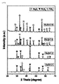
CuKα線を利用したX‐線回折分析結果、図3及び4を参照すれば、製造例1及び2の鉄前駆体である硝酸鉄水和物(Fe(NO3)3・9H2O)と水酸化鉄(γ‐FeOOH)がチオ尿素とそれぞれ反応して(111)、(200)、(210)、(211)、(220)、(311)、(222)及び(321)面のXRDピークがそれぞれ2θ =28.4±0.2゜、32.9±0.2゜、36.9±0.2゜、40.6±0.2゜、47.3±0.2゜、56.0±0.2゜、58.9±0.2゜、61.5±0.2゜及び64.0±0.2゜でXRDピークを示し、製造例1及び2の鉄前駆体である硝酸鉄水和物(Fe(NO3)3・9H2O)、水酸化鉄(γ‐FeOOH)が過量の硫黄と反応して純粋な相の結晶性硫化鉄(FeS2)を形成したことを確認することができ、硫黄のXRDピークが観察されていないことからみて、過量の硫黄は熱処理の昇温過程で全て取り除かれたことが分かった。 As a result of X-ray diffraction analysis using CuKα ray, referring to FIGS. 3 and 4, iron nitrate hydrate (Fe (NO 3 ) 3.9H 2 O) which is an iron precursor of Production Examples 1 and 2 and Iron hydroxide (γ-FeOOH) reacts with thiourea, respectively, to form (111), (200), (210), (211), (220), (311), (222) and (321) planes XRD. Peaks are 2θ = 28.4 ± 0.2 °, 32.9 ± 0.2 °, 36.9 ± 0.2 °, 40.6 ± 0.2 °, 47.3 ± 0.2 °, respectively, The iron precursors of Production Examples 1 and 2 showed XRD peaks at 56.0 ± 0.2 °, 58.9 ± 0.2 °, 61.5 ± 0.2 ° and 64.0 ± 0.2 °. Iron nitrate hydrate (Fe (NO 3 ) 3.9H 2 O) and iron hydroxide (γ-FeOOH) react with excess sulfur to form pure phase crystalline iron sulfide (FeS 2 ). From the fact that the XRD peak of sulfur was not observed, it was found that the excess sulfur was completely removed during the heating process of the heat treatment.
一方、比較製造例1ないし3による生成物に対するXRD分析結果をそれぞれ図5ないし図7に示す。 On the other hand, the XRD analysis results for the products according to Comparative Production Examples 1 to 3 are shown in FIGS. 5 to 7, respectively.
図5を見れば、鉄(Fe)と硫黄(S)のモル比を1:4にした比較製造例1の場合、本発明で目的とする硫化鉄(FeS2)の代わりにFe7S8のピークを確認し、鉄(Fe)と硫黄(S)のモル比は1:10以上にする場合、本発明による単一相の硫化鉄(FeS2)が合成されることを確認し、鉄(Fe)と硫黄(S)のモル比は製造される最終産物の組成に影響を及ぼすことが分かった。 Looking at FIG. 5, in the case of Comparative Production Example 1 in which the molar ratio of iron (Fe) to sulfur (S) is 1: 4, Fe 7 S 8 is used instead of iron sulfide (FeS 2 ), which is the object of the present invention. When the molar ratio of iron (Fe) to sulfur (S) is 1:10 or more, it is confirmed that single-phase iron sulfide (FeS 2 ) according to the present invention is synthesized, and iron is confirmed. It was found that the molar ratio of (Fe) to sulfur (S) affects the composition of the final product produced.
図6を見れば、硫黄前駆体でチオ硫酸アンモニウム(Ammonium Thiosulfate、(NH4)2S2O3)を使用する場合、副反応が起きて硫化鉄(FeS2)の代わりにNH4Fe(SO4)2のピークが示されることを確認することができた。 Looking at FIG. 6, when ammonium thiosulfate ((NH 4 ) 2 S 2 O 3 ) is used as the sulfur precursor, a side reaction occurs and NH 4 Fe (SO) is used instead of iron sulfide (FeS 2 ). 4 ) It was confirmed that the peak of 2 was shown.
図7を見れば、硫黄前駆体で硫黄(S)自体を使用する場合、鉄(Fe)と硫黄(S)のモル比を1:10にした場合も単一相のFeS2の代わりにFe7S8が混合されて生成されることを確認し、鉄(Fe)と硫黄(S)のモル比が1:2以下の場合は、本発明で目的とするFeS2は生成されず、硫黄の割合が不足した結果、Fe7S8及び鉄酸化物(Fe3O4)が混在して生成されることを確認することができた。 Looking at FIG. 7, when sulfur (S) itself is used as the sulfur precursor, even when the molar ratio of iron (Fe) to sulfur (S) is 1:10, Fe instead of single-phase FeS 2 7 Confirm that S 8 is mixed and produced, and if the molar ratio of iron (Fe) and sulfur (S) is 1: 2 or less, FeS 2 as the object of the present invention is not produced and sulfur. As a result of the insufficient ratio of Fe 7 S 8, it was confirmed that Fe 7 S 8 and iron oxide (Fe 3 O 4 ) were mixed and produced.
[実施例1]硫化鉄が添加された正極を含むリチウム二次電池の製造
先ず、溶媒として水に硫化鉄(FeS2)を投入するベース固形分(活物質、導電材及びバインダー)に総重量(100重量部)に対して前記製造例1で製造された5重量部の硫化鉄(FeS2)を投入して溶解した。以後、得られた溶液に対して、ベース固形分総100重量部、すなわち活物質で硫黄‐炭素複合体(S/CNT 75:25の重量比)を90重量部、導電材でデンカブラックを5重量部、バインダーでスチレンブタジエンゴム/カルボキシメチルセルロース(SBR/CMC 7:3)5重量部を投入して混合して正極スラリー組成物を製造した。
[Example 1] Manufacture of a lithium secondary battery containing a positive electrode to which iron sulfide is added.
First, 5 parts by weight of the base solid content (active material, conductive material and binder) produced in Production Example 1 with respect to the total weight (100 parts by weight) of iron sulfide (FeS 2 ) added to water as a solvent. Iron sulfide (FeS 2 ) was added and dissolved. After that, with respect to the obtained solution, the total base solid content was 100 parts by weight, that is, 90 parts by weight of the sulfur-carbon composite (S / CNT 75:25 weight ratio) as the active material, and 5 parts of denca black as the conductive material. By weight, 5 parts by weight of styrene-butadiene rubber / carboxymethyl cellulose (SBR / CMC 7: 3) was added and mixed with a binder to produce a positive electrode slurry composition.
次いで、前記製造されたスラリー組成物を集電体(Al Foil)上にコーティングして50℃で12時間乾燥し、ロールプレス(roll press)機器で圧搾して正極を製造した。この時、ローディング量は5.3mAh/cm2で、電極の気孔率(porosity)は68%にした。 Then, the produced slurry composition was coated on a current collector (AlFoil), dried at 50 ° C. for 12 hours, and pressed with a roll press device to produce a positive electrode. At this time, the loading amount was 5.3 mAh / cm 2 , and the porosity of the electrode was 68%.
以後、上述したとおり製造された正極、負極、分離膜及び電解液を含むリチウム二次電池のコインセルを下記のように製造した。具体的に、前記正極は14phi円形電極で打ち抜いて使用し、ポリエチレン(PE)分離膜は19phi、150μmのリチウム金属は負極として16phiで打ち抜いて使用した。 Hereinafter, a coin cell of a lithium secondary battery including a positive electrode, a negative electrode, a separation membrane and an electrolytic solution manufactured as described above was manufactured as follows. Specifically, the positive electrode was punched out with a 14 phi circular electrode, the polyethylene (PE) separation membrane was punched out at 19 phi, and the 150 μm lithium metal was punched out at 16 phi as the negative electrode.
[実施例2]硫化鉄が添加された正極を含むリチウム二次電池の製造
前記製造例1で製造された硫化鉄(FeS2)の代わりに前記製造例2で製造された板状粒子を有する硫化鉄(FeS2)を使用したことを除いては、前記実施例1と同様に行ってリチウム二次電池を製造した(すなわち、電極気孔率は68%)。
[Example 2] Manufacture of a lithium secondary battery containing a positive electrode to which iron sulfide is added.
Except for the fact that iron sulfide (FeS 2 ) having plate-like particles produced in Production Example 2 was used instead of iron sulfide (FeS 2 ) produced in Production Example 1, the same as in Example 1. A lithium secondary battery was manufactured in the same manner (that is, the electrode porosity was 68%).
[実施例3]硫化鉄が添加された正極を含むリチウム二次電池の製造
前記製造例2で製造された板状粒子を有する硫化鉄(FeS2)を含む電極を圧延し、電極の気孔率(porosity)を68%から62%に変更したことを除いては、前記実施例2と同様に行ってリチウム二次電池を製造した。
[Example 3] Production of a lithium secondary battery containing a positive electrode to which iron sulfide is added.
Except that the electrode containing iron sulfide (FeS 2 ) having plate-like particles produced in Production Example 2 was rolled and the porosity of the electrode was changed from 68% to 62%. A lithium secondary battery was manufactured in the same manner as in Example 2.
[比較例1]硫化鉄が添加されていない正極を含むリチウム二次電池の製造
硫化鉄(FeS2)を含まずに溶媒として水にベース固形分総100重量部、すなわち活物質で硫黄‐炭素複合体(S/CNT 75:25の重量比)を90重量部、導電材でデンカブラックを5重量部、バインダーでスチレンブタジエンゴム/カルボキシメチルセルロース(SBR/CMC 7:3)5重量部を投入して混合して正極スラリー組成物を製造した。
[Comparative Example 1] Manufacture of a lithium secondary battery containing a positive electrode to which iron sulfide is not added.
A total of 100 parts by weight of the base solid content in water as a solvent without containing iron sulfide (FeS 2 ), that is, 90 parts by weight of a sulfur-carbon composite (S / CNT 75:25 weight ratio) as an active material, and a conductive material. 5 parts by weight of Denca Black and 5 parts by weight of styrene butadiene rubber / carboxymethyl cellulose (SBR / CMC 7: 3) with a binder were added and mixed to produce a positive electrode slurry composition.
次いで、前記製造されたスラリー組成物を集電体(Al Foil)上にコーティングして50℃で12時間乾燥して正極を製造した。この時、ローディング量は5.3mAh/cm2で、電極の孔隙率(porosity)は68%にした。 Next, the produced slurry composition was coated on a current collector (AlFoil) and dried at 50 ° C. for 12 hours to produce a positive electrode. At this time, the loading amount was 5.3 mAh / cm 2 , and the porosity of the electrodes was 68%.
以後、上述したとおり製造された正極、負極、分離膜及び電解液を含むリチウム二次電池のコインセルを下記のように製造した。具体的に、前記正極は14phi円形電極で打ち抜いて使用し、ポリエチレン(PE)分離膜は19phi、150μmのリチウム金属は負極として16phiで打ち抜いて使用した。 Hereinafter, a coin cell of a lithium secondary battery including a positive electrode, a negative electrode, a separation membrane and an electrolytic solution manufactured as described above was manufactured as follows. Specifically, the positive electrode was punched out with a 14 phi circular electrode, the polyethylene (PE) separation membrane was punched out at 19 phi, and the 150 μm lithium metal was punched out at 16 phi as the negative electrode.
[比較例2]硫化鉄が添加されていない正極を含むリチウム二次電池の製造
電極を圧延して電極の気孔率を68%から62%に変更したことを除いては、前記比較例2と同様に行ってリチウム二次電池を製造した。
[Comparative Example 2] Manufacture of a lithium secondary battery containing a positive electrode to which iron sulfide is not added.
A lithium secondary battery was manufactured in the same manner as in Comparative Example 2 except that the electrode was rolled to change the porosity of the electrode from 68% to 62%.
[実験例3]リチウム二次電池の放電容量比較実験
正極材の種類によるリチウム二次電池の放電容量を実験するために、下記表1に記載したように、前記実施例1ないし3、比較例1及び2で製造されたリチウム二次電池の放電容量を測定した。この時、測定電流は0.1C、電圧範囲1.8ないし2.6Vにし、その結果を図8及び9に図示した。
[Experimental Example 3] Discharge capacity comparison experiment of lithium secondary battery
In order to experiment with the discharge capacity of the lithium secondary battery depending on the type of positive electrode material, as shown in Table 1 below, the discharge capacity of the lithium secondary batteries manufactured in Examples 1 to 3 and Comparative Examples 1 and 2 is described. Was measured. At this time, the measured current was 0.1 C and the voltage range was 1.8 to 2.6 V, and the results are shown in FIGS. 8 and 9.

図8及び9は、本発明の一実施例及び比較例によって製造されたリチウム二次電池の放電容量測定結果を示すグラフである。図8に図示されたように、前記製造例1で製造された硫化鉄(FeS2)が正極に添加された実施例1と、前記製造例2で製造された硫化鉄(FeS2)が正極に添加された実施例2は、通常の比較例1に比べて電池の過電圧が改善され、初期放電容量がさらに増加したことを確認することができた。よって、本発明による硫化鉄がリチウム二次電池の初期放電容量の増加及び過電圧改善効果があることが分かった。 8 and 9 are graphs showing the discharge capacity measurement results of the lithium secondary batteries manufactured according to the examples of the present invention and the comparative examples. As shown in FIG. 8, Example 1 in which iron sulfide (FeS 2 ) produced in Production Example 1 is added to the positive electrode and iron sulfide (FeS 2 ) produced in Production Example 2 are positive electrodes. In Example 2 added to, it was confirmed that the overvoltage of the battery was improved and the initial discharge capacity was further increased as compared with the usual Comparative Example 1. Therefore, it was found that iron sulfide according to the present invention has the effect of increasing the initial discharge capacity of the lithium secondary battery and improving the overvoltage.
特に、硫化鉄の鉄前駆体で水酸化鉄(γ‐FeOOH)を利用した実施例2は、図8に図示されたように、硫化鉄の鉄前駆体で硝酸鉄水和物(Fe(NO3)3・9H2O)を利用した実施例1に比べても初期放電容量に優れることを確認することができ、XRD分析に関する前記実験例2で水酸化鉄を適用した硫化鉄と硝酸鉄(III)九水和物を適用した硫化鉄が同一な結晶構造を持つにもかかわらず、このように異なる電池性能を示すことから、硫化鉄の構造的差が電池の性能改善にさらに重要な役目をすることが分かる。 In particular, in Example 2 in which iron hydroxide (γ-FeOOH) was used as an iron precursor of iron sulfide, as shown in FIG. 8, iron nitrate hydrate (Fe (NO)) was used as an iron precursor of iron sulfide. 3 ) It was confirmed that the initial discharge capacity was superior to that of Example 1 using 3.9H 2 O), and iron sulfide and iron nitrate to which iron hydroxide was applied in Experimental Example 2 regarding XRD analysis could be confirmed. (III) Since iron sulfide to which nine hydrate is applied has the same crystal structure but exhibits such different battery performance, the structural difference of iron sulfide is more important for improving the performance of the battery. It turns out that it plays a role.
よって、以上の内容を通じて、硫化鉄(FeS2)を正極に添加するものの、硝酸鉄水和物(Fe(NO3)3・9H2O)よりは水酸化鉄(γ‐FeOOH)を鉄前駆体にして製造した硫化鉄(FeS2)を使用することがより好ましいことを確認することができた。 Therefore, through the above contents, although iron sulfide (FeS 2 ) is added to the positive electrode, iron hydroxide (γ-FeOOH) is an iron precursor rather than iron nitrate hydrate (Fe (NO 3 ) 3.9H 2 O). It was confirmed that it is more preferable to use iron sulfide (FeS 2 ) produced as a body.
一方、一般的なリチウム二次電池の場合、電極の気孔率を下げると電極に含まれる電解質の減少によって電池性能が低下するが、図9に図示されたように、電極の気孔率を下げた場合も電極の初期放電容量が増加して過電圧が改善されることが分かった(実施例3と比較例2の比較対照)。よって、本発明による硫化鉄(FeS2)が高ローディングの低い気孔率の電極でも過電圧改善及び放電容量を向上させる効果があることが分かった。 On the other hand, in the case of a general lithium secondary battery, when the pore ratio of the electrode is lowered, the battery performance is lowered due to the decrease of the electrolyte contained in the electrode, but as shown in FIG. 9, the pore ratio of the electrode is lowered. In this case as well, it was found that the initial discharge capacity of the electrode was increased and the overvoltage was improved (comparison control between Example 3 and Comparative Example 2). Therefore, it was found that iron sulfide (FeS 2 ) according to the present invention has the effect of improving the overvoltage and the discharge capacity even with an electrode having a high loading and a low porosity.
Claims (5)
(2)前記混合物を非活性気体の雰囲気で熱処理する段階;を含み、
前記鉄前駆体はFe(NO 3 ) 3 ・9H 2 O、γ‐FeOOH、またはこの組み合わせであり、
前記硫黄前駆体はチオ尿素であり、
前記段階(1)の混合は、鉄(Fe)と硫黄(S)のモル比が1:8以上である、硫化鉄(FeS2)の製造方法。 It comprises (1) a step of mixing an iron precursor and a sulfur precursor to form a mixture; and (2) a step of heat treating the mixture in an atmosphere of an inert gas;
The iron precursor is Fe (NO 3 ) 3.9H 2 O , γ-FeOOH, or a combination thereof.
The sulfur precursor is thiourea,
The mixing in the step (1) is a method for producing iron sulfide (FeS 2 ), wherein the molar ratio of iron (Fe) to sulfur (S) is 1: 8 or more .
Applications Claiming Priority (9)
| Application Number | Priority Date | Filing Date | Title |
|---|---|---|---|
| KR20180111792 | 2018-09-18 | ||
| KR10-2018-0111792 | 2018-09-18 | ||
| KR20180111788 | 2018-09-18 | ||
| KR10-2018-0111788 | 2018-09-18 | ||
| KR10-2019-0114782 | 2019-09-18 | ||
| KR10-2019-0114771 | 2019-09-18 | ||
| KR1020190114782A KR102781564B1 (en) | 2018-09-18 | 2019-09-18 | Cathode for lithium secondary battery comprising pyrite, and lithium secondary battery comprising thereof |
| KR1020190114771A KR102931098B1 (en) | 2018-09-18 | 2019-09-18 | Method for preparing pyrite |
| PCT/KR2019/012089 WO2020060199A1 (en) | 2018-09-18 | 2019-09-18 | Method for preparing iron sulfide, cathode comprising iron sulfide prepared thereby for lithium secondary battery, and lithium secondary battery comprising same |
Publications (2)
| Publication Number | Publication Date |
|---|---|
| JP2021531228A JP2021531228A (en) | 2021-11-18 |
| JP7098043B2 true JP7098043B2 (en) | 2022-07-08 |
Family
ID=74586282
Family Applications (1)
| Application Number | Title | Priority Date | Filing Date |
|---|---|---|---|
| JP2021500722A Active JP7098043B2 (en) | 2018-09-18 | 2019-09-18 | A method for producing iron sulfide, a positive electrode for a lithium secondary battery containing iron sulfide produced from the method, and a lithium secondary battery provided with the positive electrode. |
Country Status (4)
| Country | Link |
|---|---|
| US (1) | US12155073B2 (en) |
| EP (1) | EP3806207B1 (en) |
| JP (1) | JP7098043B2 (en) |
| CN (1) | CN112385061B (en) |
Families Citing this family (7)
| Publication number | Priority date | Publication date | Assignee | Title |
|---|---|---|---|---|
| WO2023000211A1 (en) * | 2021-07-21 | 2023-01-26 | 宁德新能源科技有限公司 | Positive electrode plate, electrochemical device comprising same, and electronic device |
| CN113908859B (en) * | 2021-11-14 | 2022-10-04 | 福州大学 | A kind of mesoporous iron disulfide catalyst and its preparation method and application |
| CN116417580A (en) * | 2021-12-31 | 2023-07-11 | 江苏延长桑莱特新能源有限公司 | A lithium-rich battery electrode material based on sulfur-carbon composites |
| JP7778420B2 (en) * | 2022-03-03 | 2025-12-02 | 国立研究開発法人産業技術総合研究所 | Lithium sulfide-iron-carbon composite |
| CN116161708A (en) * | 2022-12-16 | 2023-05-26 | 浙江工业大学 | A kind of preparation method of synthetic pyrite by hydrothermal method |
| CN116177612B (en) * | 2023-01-19 | 2024-05-24 | 深圳大学 | A lithium ion battery positive electrode material and preparation method thereof, and a lithium ion battery and preparation method thereof |
| CN119680581B (en) * | 2024-12-17 | 2025-10-03 | 太原理工大学 | FeS (FeS)2Preparation and application of @ FeOOH three-dimensional particles |
Citations (7)
| Publication number | Priority date | Publication date | Assignee | Title |
|---|---|---|---|---|
| WO2009028326A1 (en) | 2007-08-24 | 2009-03-05 | National Institute Of Advanced Industrial Science And Technology | Process for producing metal sulfide |
| JP2010540387A (en) | 2007-09-28 | 2010-12-24 | エバレデイ バツテリ カンパニー インコーポレーテツド | Process for producing synthetic pyrite |
| JP2011512613A (en) | 2007-10-19 | 2011-04-21 | エバレデイ バツテリ カンパニー インコーポレーテツド | Lithium-iron disulfide battery design |
| WO2016080443A1 (en) | 2014-11-18 | 2016-05-26 | 国立研究開発法人産業技術総合研究所 | Lithium-iron-phosphorus-sulfur-carbon composite body and method for producing same |
| CN107482185A (en) | 2017-07-25 | 2017-12-15 | 东莞市天球实业有限公司 | A kind of FeS2The synthetic method and battery of composite positive pole |
| WO2018084449A2 (en) | 2016-11-02 | 2018-05-11 | 주식회사 엘지화학 | Sulfur-carbon composite and lithium-sulfur battery comprising same |
| WO2018164413A1 (en) | 2017-03-07 | 2018-09-13 | 주식회사 엘지화학 | Carbon-sulfur complex, method for producing same, and cathode and lithium-sulfur battery comprising same |
Family Cites Families (12)
| Publication number | Priority date | Publication date | Assignee | Title |
|---|---|---|---|---|
| JPS6027147B2 (en) * | 1977-04-05 | 1985-06-27 | 日立マクセル株式会社 | Manufacturing method of non-aqueous electrolyte battery |
| JPH08157221A (en) | 1994-11-29 | 1996-06-18 | Sakai Chem Ind Co Ltd | Iron disulfide and its production |
| US20080026293A1 (en) | 2006-07-26 | 2008-01-31 | Eveready Battery Company, Inc. | Lithium-iron disulfide cylindrical cell with modified positive electrode |
| CN101521279A (en) | 2009-03-18 | 2009-09-02 | 广州市天球实业有限公司 | Anode material and anode plate of lithium-iron disulfide battery and method for preparing same |
| WO2011025538A1 (en) | 2009-08-27 | 2011-03-03 | Eveready Battery Company, Inc. | Lithium-iron disulfide cathode formulation having high pyrite content and low conductive additives |
| DE102015210402A1 (en) | 2015-06-05 | 2016-12-08 | Robert Bosch Gmbh | Cathode material for lithium-sulfur cell |
| JP2017157473A (en) | 2016-03-03 | 2017-09-07 | 三星電子株式会社Samsung Electronics Co.,Ltd. | Lithium ion secondary battery |
| KR102161590B1 (en) | 2016-03-29 | 2020-10-05 | 주식회사 엘지화학 | Method for preparing positive electrode of secondary battery, and positive electrode and secondary battery prepared using the same |
| KR102006727B1 (en) | 2016-11-02 | 2019-08-02 | 주식회사 엘지화학 | Sulfur-carbon composite and lithium-sulfur battery including the same |
| CN109565073A (en) | 2016-11-28 | 2019-04-02 | 株式会社Lg化学 | Positive electrode active material for lithium-sulfur battery containing metal sulfide nanoparticles and method for producing same |
| KR101901650B1 (en) | 2017-02-21 | 2018-09-27 | 영남대학교 산학협력단 | Method of fabricating FeS2 nanocrystals |
| CN107611409B (en) * | 2017-09-27 | 2020-07-03 | 中南大学 | A kind of preparation method of sheet-like nano FeS2/C negative electrode material |
-
2019
- 2019-09-18 EP EP19863940.3A patent/EP3806207B1/en active Active
- 2019-09-18 US US17/259,215 patent/US12155073B2/en active Active
- 2019-09-18 JP JP2021500722A patent/JP7098043B2/en active Active
- 2019-09-18 CN CN201980045775.1A patent/CN112385061B/en active Active
Patent Citations (7)
| Publication number | Priority date | Publication date | Assignee | Title |
|---|---|---|---|---|
| WO2009028326A1 (en) | 2007-08-24 | 2009-03-05 | National Institute Of Advanced Industrial Science And Technology | Process for producing metal sulfide |
| JP2010540387A (en) | 2007-09-28 | 2010-12-24 | エバレデイ バツテリ カンパニー インコーポレーテツド | Process for producing synthetic pyrite |
| JP2011512613A (en) | 2007-10-19 | 2011-04-21 | エバレデイ バツテリ カンパニー インコーポレーテツド | Lithium-iron disulfide battery design |
| WO2016080443A1 (en) | 2014-11-18 | 2016-05-26 | 国立研究開発法人産業技術総合研究所 | Lithium-iron-phosphorus-sulfur-carbon composite body and method for producing same |
| WO2018084449A2 (en) | 2016-11-02 | 2018-05-11 | 주식회사 엘지화학 | Sulfur-carbon composite and lithium-sulfur battery comprising same |
| WO2018164413A1 (en) | 2017-03-07 | 2018-09-13 | 주식회사 엘지화학 | Carbon-sulfur complex, method for producing same, and cathode and lithium-sulfur battery comprising same |
| CN107482185A (en) | 2017-07-25 | 2017-12-15 | 东莞市天球实业有限公司 | A kind of FeS2The synthetic method and battery of composite positive pole |
Also Published As
| Publication number | Publication date |
|---|---|
| EP3806207A4 (en) | 2021-08-25 |
| JP2021531228A (en) | 2021-11-18 |
| CN112385061A (en) | 2021-02-19 |
| US12155073B2 (en) | 2024-11-26 |
| EP3806207A1 (en) | 2021-04-14 |
| EP3806207B1 (en) | 2026-04-01 |
| CN112385061B (en) | 2024-08-16 |
| US20210273225A1 (en) | 2021-09-02 |
Similar Documents
| Publication | Publication Date | Title |
|---|---|---|
| JP7098043B2 (en) | A method for producing iron sulfide, a positive electrode for a lithium secondary battery containing iron sulfide produced from the method, and a lithium secondary battery provided with the positive electrode. | |
| KR102268185B1 (en) | METHOD FOR PREPARING FeOOH, AND CATHODE FOR LITHIUM-SULFUR BATTERY COMPRISING FeOOH | |
| JP2021516654A (en) | A method for producing a carbon nanostructure containing molybdenum disulfide, a positive electrode for a lithium secondary battery containing the carbon nanostructure containing molybdenum disulfide produced thereby, and a lithium secondary battery provided with the positive electrode. | |
| KR20200001369A (en) | Mesoporous titanium nitride, method for preparing the same, and lithium sulfur battery comprising the same | |
| KR102229456B1 (en) | Cathode for lithium secondary battery comprising iron oxyhydroxynitrate, and lithium secondary battery comprising thereof | |
| JP7282116B2 (en) | Method for producing iron phosphide, positive electrode for lithium secondary battery containing iron phosphide, and lithium secondary battery having the same | |
| JP7062067B2 (en) | A method for producing iron oxyhydroxide, a positive electrode for a lithium secondary battery containing iron oxyhydroxide produced thereby, and a lithium secondary battery provided with the positive electrode. | |
| KR102781564B1 (en) | Cathode for lithium secondary battery comprising pyrite, and lithium secondary battery comprising thereof | |
| CN112204779B (en) | Positive electrode for lithium secondary battery containing goethite and lithium secondary battery containing the positive electrode | |
| KR20200029276A (en) | Cathode for lithium secondary battery comprising molybdenum disulfide, and lithium secondary battery comprising thereof | |
| KR102183665B1 (en) | Positive electrode for lithium secondary battery including iron phosphide and lithium secondary battery comprising thereof | |
| JP7046194B2 (en) | Positive electrode for lithium secondary battery containing iron oxide and lithium secondary battery equipped with this | |
| JP6797461B2 (en) | Positive electrode for lithium-sulfur battery containing maghemite and lithium-sulfur battery equipped with this |
Legal Events
| Date | Code | Title | Description |
|---|---|---|---|
| A621 | Written request for application examination |
Free format text: JAPANESE INTERMEDIATE CODE: A621 Effective date: 20210108 |
|
| A131 | Notification of reasons for refusal |
Free format text: JAPANESE INTERMEDIATE CODE: A131 Effective date: 20211213 |
|
| A711 | Notification of change in applicant |
Free format text: JAPANESE INTERMEDIATE CODE: A712 Effective date: 20211227 |
|
| A521 | Request for written amendment filed |
Free format text: JAPANESE INTERMEDIATE CODE: A523 Effective date: 20220309 |
|
| A521 | Request for written amendment filed |
Free format text: JAPANESE INTERMEDIATE CODE: A523 Effective date: 20220324 |
|
| TRDD | Decision of grant or rejection written | ||
| A01 | Written decision to grant a patent or to grant a registration (utility model) |
Free format text: JAPANESE INTERMEDIATE CODE: A01 Effective date: 20220530 |
|
| A61 | First payment of annual fees (during grant procedure) |
Free format text: JAPANESE INTERMEDIATE CODE: A61 Effective date: 20220628 |
|
| R150 | Certificate of patent or registration of utility model |
Ref document number: 7098043 Country of ref document: JP Free format text: JAPANESE INTERMEDIATE CODE: R150 |
|
| R250 | Receipt of annual fees |
Free format text: JAPANESE INTERMEDIATE CODE: R250 |