JP7100320B2 - Fe-based sintered body, manufacturing method of Fe-based sintered body, and hot pressing die - Google Patents
Fe-based sintered body, manufacturing method of Fe-based sintered body, and hot pressing die Download PDFInfo
- Publication number
- JP7100320B2 JP7100320B2 JP2018148885A JP2018148885A JP7100320B2 JP 7100320 B2 JP7100320 B2 JP 7100320B2 JP 2018148885 A JP2018148885 A JP 2018148885A JP 2018148885 A JP2018148885 A JP 2018148885A JP 7100320 B2 JP7100320 B2 JP 7100320B2
- Authority
- JP
- Japan
- Prior art keywords
- sintered body
- based sintered
- matrix
- sintering
- phase
- Prior art date
- Legal status (The legal status is an assumption and is not a legal conclusion. Google has not performed a legal analysis and makes no representation as to the accuracy of the status listed.)
- Active
Links
Images





Classifications
-
- C—CHEMISTRY; METALLURGY
- C22—METALLURGY; FERROUS OR NON-FERROUS ALLOYS; TREATMENT OF ALLOYS OR NON-FERROUS METALS
- C22C—ALLOYS
- C22C33/00—Making ferrous alloys
- C22C33/02—Making ferrous alloys by powder metallurgy
- C22C33/0257—Making ferrous alloys by powder metallurgy characterised by the range of the alloying elements
- C22C33/0278—Making ferrous alloys by powder metallurgy characterised by the range of the alloying elements with at least one alloying element having a minimum content above 5%
- C22C33/0292—Making ferrous alloys by powder metallurgy characterised by the range of the alloying elements with at least one alloying element having a minimum content above 5% with more than 5% preformed carbides, nitrides or borides
-
- B—PERFORMING OPERATIONS; TRANSPORTING
- B22—CASTING; POWDER METALLURGY
- B22F—WORKING METALLIC POWDER; MANUFACTURE OF ARTICLES FROM METALLIC POWDER; MAKING METALLIC POWDER; APPARATUS OR DEVICES SPECIALLY ADAPTED FOR METALLIC POWDER
- B22F3/00—Manufacture of workpieces or articles from metallic powder characterised by the manner of compacting or sintering; Apparatus specially adapted therefor ; Presses and furnaces
- B22F3/004—Filling molds with powder
-
- B—PERFORMING OPERATIONS; TRANSPORTING
- B22—CASTING; POWDER METALLURGY
- B22F—WORKING METALLIC POWDER; MANUFACTURE OF ARTICLES FROM METALLIC POWDER; MAKING METALLIC POWDER; APPARATUS OR DEVICES SPECIALLY ADAPTED FOR METALLIC POWDER
- B22F3/00—Manufacture of workpieces or articles from metallic powder characterised by the manner of compacting or sintering; Apparatus specially adapted therefor ; Presses and furnaces
- B22F3/10—Sintering only
- B22F3/1039—Sintering only by reaction
-
- B—PERFORMING OPERATIONS; TRANSPORTING
- B22—CASTING; POWDER METALLURGY
- B22F—WORKING METALLIC POWDER; MANUFACTURE OF ARTICLES FROM METALLIC POWDER; MAKING METALLIC POWDER; APPARATUS OR DEVICES SPECIALLY ADAPTED FOR METALLIC POWDER
- B22F3/00—Manufacture of workpieces or articles from metallic powder characterised by the manner of compacting or sintering; Apparatus specially adapted therefor ; Presses and furnaces
- B22F3/10—Sintering only
- B22F3/105—Sintering only by using electric current other than for infrared radiant energy, laser radiation or plasma ; by ultrasonic bonding
-
- B—PERFORMING OPERATIONS; TRANSPORTING
- B22—CASTING; POWDER METALLURGY
- B22F—WORKING METALLIC POWDER; MANUFACTURE OF ARTICLES FROM METALLIC POWDER; MAKING METALLIC POWDER; APPARATUS OR DEVICES SPECIALLY ADAPTED FOR METALLIC POWDER
- B22F3/00—Manufacture of workpieces or articles from metallic powder characterised by the manner of compacting or sintering; Apparatus specially adapted therefor ; Presses and furnaces
- B22F3/12—Both compacting and sintering
- B22F3/14—Both compacting and sintering simultaneously
-
- B—PERFORMING OPERATIONS; TRANSPORTING
- B22—CASTING; POWDER METALLURGY
- B22F—WORKING METALLIC POWDER; MANUFACTURE OF ARTICLES FROM METALLIC POWDER; MAKING METALLIC POWDER; APPARATUS OR DEVICES SPECIALLY ADAPTED FOR METALLIC POWDER
- B22F5/00—Manufacture of workpieces or articles from metallic powder characterised by the special shape of the product
- B22F5/007—Manufacture of workpieces or articles from metallic powder characterised by the special shape of the product of moulds
-
- B—PERFORMING OPERATIONS; TRANSPORTING
- B22—CASTING; POWDER METALLURGY
- B22F—WORKING METALLIC POWDER; MANUFACTURE OF ARTICLES FROM METALLIC POWDER; MAKING METALLIC POWDER; APPARATUS OR DEVICES SPECIALLY ADAPTED FOR METALLIC POWDER
- B22F9/00—Making metallic powder or suspensions thereof
- B22F9/02—Making metallic powder or suspensions thereof using physical processes
- B22F9/04—Making metallic powder or suspensions thereof using physical processes starting from solid material, e.g. by crushing, grinding or milling
-
- C—CHEMISTRY; METALLURGY
- C22—METALLURGY; FERROUS OR NON-FERROUS ALLOYS; TREATMENT OF ALLOYS OR NON-FERROUS METALS
- C22C—ALLOYS
- C22C38/00—Ferrous alloys, e.g. steel alloys
-
- B—PERFORMING OPERATIONS; TRANSPORTING
- B22—CASTING; POWDER METALLURGY
- B22F—WORKING METALLIC POWDER; MANUFACTURE OF ARTICLES FROM METALLIC POWDER; MAKING METALLIC POWDER; APPARATUS OR DEVICES SPECIALLY ADAPTED FOR METALLIC POWDER
- B22F3/00—Manufacture of workpieces or articles from metallic powder characterised by the manner of compacting or sintering; Apparatus specially adapted therefor ; Presses and furnaces
- B22F3/10—Sintering only
- B22F3/105—Sintering only by using electric current other than for infrared radiant energy, laser radiation or plasma ; by ultrasonic bonding
- B22F2003/1051—Sintering only by using electric current other than for infrared radiant energy, laser radiation or plasma ; by ultrasonic bonding by electric discharge
-
- B—PERFORMING OPERATIONS; TRANSPORTING
- B22—CASTING; POWDER METALLURGY
- B22F—WORKING METALLIC POWDER; MANUFACTURE OF ARTICLES FROM METALLIC POWDER; MAKING METALLIC POWDER; APPARATUS OR DEVICES SPECIALLY ADAPTED FOR METALLIC POWDER
- B22F9/00—Making metallic powder or suspensions thereof
- B22F9/02—Making metallic powder or suspensions thereof using physical processes
- B22F9/04—Making metallic powder or suspensions thereof using physical processes starting from solid material, e.g. by crushing, grinding or milling
- B22F2009/043—Making metallic powder or suspensions thereof using physical processes starting from solid material, e.g. by crushing, grinding or milling by ball milling
-
- B—PERFORMING OPERATIONS; TRANSPORTING
- B22—CASTING; POWDER METALLURGY
- B22F—WORKING METALLIC POWDER; MANUFACTURE OF ARTICLES FROM METALLIC POWDER; MAKING METALLIC POWDER; APPARATUS OR DEVICES SPECIALLY ADAPTED FOR METALLIC POWDER
- B22F2301/00—Metallic composition of the powder or its coating
- B22F2301/35—Iron
-
- B—PERFORMING OPERATIONS; TRANSPORTING
- B22—CASTING; POWDER METALLURGY
- B22F—WORKING METALLIC POWDER; MANUFACTURE OF ARTICLES FROM METALLIC POWDER; MAKING METALLIC POWDER; APPARATUS OR DEVICES SPECIALLY ADAPTED FOR METALLIC POWDER
- B22F2302/00—Metal Compound, non-Metallic compound or non-metal composition of the powder or its coating
- B22F2302/05—Boride
-
- B—PERFORMING OPERATIONS; TRANSPORTING
- B22—CASTING; POWDER METALLURGY
- B22F—WORKING METALLIC POWDER; MANUFACTURE OF ARTICLES FROM METALLIC POWDER; MAKING METALLIC POWDER; APPARATUS OR DEVICES SPECIALLY ADAPTED FOR METALLIC POWDER
- B22F2998/00—Supplementary information concerning processes or compositions relating to powder metallurgy
- B22F2998/10—Processes characterised by the sequence of their steps
-
- B—PERFORMING OPERATIONS; TRANSPORTING
- B22—CASTING; POWDER METALLURGY
- B22F—WORKING METALLIC POWDER; MANUFACTURE OF ARTICLES FROM METALLIC POWDER; MAKING METALLIC POWDER; APPARATUS OR DEVICES SPECIALLY ADAPTED FOR METALLIC POWDER
- B22F2999/00—Aspects linked to processes or compositions used in powder metallurgy
Landscapes
- Engineering & Computer Science (AREA)
- Mechanical Engineering (AREA)
- Chemical & Material Sciences (AREA)
- Manufacturing & Machinery (AREA)
- Materials Engineering (AREA)
- Metallurgy (AREA)
- Organic Chemistry (AREA)
- Physics & Mathematics (AREA)
- Optics & Photonics (AREA)
- Chemical Kinetics & Catalysis (AREA)
- Powder Metallurgy (AREA)
- Ceramic Products (AREA)
Description
本発明は、Fe基焼結体、Fe基焼結体の製造方法、および熱間プレス用金型に関する。 The present invention relates to a Fe-based sintered body, a method for manufacturing the Fe-based sintered body, and a hot pressing die.
従来、例えば自動車の車体部品等の製造に熱間プレス技術が用いられている。熱間プレス技術では、鋼板を加熱した状態にて、熱間プレス用金型を用いて当該鋼板をプレスすることにより成形(プレス成形)を行う。このプレス成形の際に急冷(焼入れ)することによって鋼を硬化させる。このような熱間プレス技術は、超高張力鋼を用いた製品(部品)を製造する場合に、成形精度および成形後の強度を確保するために重要な技術となってきている。 Conventionally, for example, hot pressing technology has been used for manufacturing automobile body parts and the like. In the hot pressing technique, molding (press forming) is performed by pressing the steel sheet with a hot pressing die while the steel sheet is heated. The steel is hardened by quenching (quenching) during this press forming. Such a hot pressing technique has become an important technique for ensuring molding accuracy and strength after molding when manufacturing a product (part) using ultra-high-strength steel.
上記熱間プレス用金型に求められる性能としては、繰返し使用することができる高い耐久性(高寿命化)および高い冷却性能が挙げられる。冷却性能が高いほどプレス成形の1サイクルの時間を短くすることができる。つまり、熱間プレス用金型は、硬度が高く、かつ熱伝導率が高い材料により形成されていることが要望される。 The performance required for the hot pressing die includes high durability (long life) and high cooling performance that can be used repeatedly. The higher the cooling performance, the shorter the time of one cycle of press molding. That is, it is required that the hot pressing die is made of a material having high hardness and high thermal conductivity.
特許文献1には、工具鋼の室温での熱伝導率を向上させる技術について記載されている。
一般に、熱間プレス用金型の材料として例えばSKD61が知られている。この材料は、ロックウェル硬さで50HRC程度の硬度を有する。一方で、該材料の熱伝導率は24W/(m・K)程度であり、熱伝導率の更なる向上が求められている。しかし、通常、材料の特性として、高い硬度を有することと高い熱伝導率を有することとは互いにトレードオフの関係にある。そのため、高い硬度と高い熱伝導率とを兼備する材料を得ることは困難である。 Generally, for example, SKD61 is known as a material for a hot pressing die. This material has a Rockwell hardness of about 50 HRC . On the other hand, the thermal conductivity of the material is about 24 W / (m · K), and further improvement of the thermal conductivity is required. However, as a characteristic of a material, having high hardness and having high thermal conductivity are usually in a trade-off relationship with each other. Therefore, it is difficult to obtain a material having both high hardness and high thermal conductivity.
特許文献1には、鋼の内部組織を冶金学的に定義することにより、室温での熱伝導率を向上させた工具鋼について記載されている。しかし、鋼の内部組織を精密に制御することは難しく、上記工具鋼は安定して製造し難いという問題を有している。
本発明は、このような現状に鑑みなされたものであって、高い硬度と高い熱伝導率とを兼備するとともに、より安定して製造可能なFe基焼結体(熱間プレス用金型の材料)を提供することを目的とする。また、高い硬度と高い熱伝導率とを兼備するFe基焼結体を、より安定して製造できるFe基焼結体の製造方法を提供することを目的とする。 The present invention has been made in view of such a current situation, and has both high hardness and high thermal conductivity, and is a Fe-based sintered body (a mold for hot pressing) that can be manufactured more stably. Material) is intended to be provided. Another object of the present invention is to provide a method for producing an Fe-based sintered body, which can more stably produce an Fe-based sintered body having both high hardness and high thermal conductivity.
上記の課題を解決するために、本発明の一態様に係るFe基焼結体は、Feを主成分とするマトリックスと、該マトリックス中に分散した分散相とを有するFe基焼結体であって、前記マトリックスは、ネットワーク状に形成されているとともに、αFeを含んでおり、前記分散相は、TiCを含む。 In order to solve the above problems, the Fe-based sintered body according to one aspect of the present invention is an Fe-based sintered body having a matrix containing Fe as a main component and a dispersed phase dispersed in the matrix. The matrix is formed in a network shape and contains αFe, and the dispersed phase contains TiC.
また、上記の課題を解決するために、本発明の一態様に係るFe基焼結体の製造方法は、Fe粉末とTiB2粉末とを含む混合粉末を加圧成形してなる成形体を、グラファイト製の加圧部材を用いて加圧しつつ加熱して焼結する焼結工程を含み、前記焼結工程では、15MPa以上の圧力範囲で加圧し、1323K以上の温度で加熱することにより、前記TiB2の少なくとも一部を分解するとともに、Feを主成分としてTiを含むネットワーク状のマトリックスを形成し、前記マトリックスはαFeを含み、前記TiB2に由来するTiと前記加圧部材に由来するCとの反応により、前記マトリックス中に分散したTiCを生成させるように焼結する。 Further, in order to solve the above-mentioned problems, the method for producing an Fe-based sintered body according to one aspect of the present invention is to obtain a molded body obtained by pressure-molding a mixed powder containing Fe powder and TiB 2 powder. The sintering step includes a sintering step of heating and sintering while pressurizing using a pressure member made of graphite. In the sintering step, the pressure is applied in a pressure range of 15 MPa or more and heated at a temperature of 1323 K or more. At least a part of TiB 2 is decomposed and a network-like matrix containing Ti as a main component is formed. The matrix contains αFe, and Ti derived from TiB 2 and C derived from the pressure member. By the reaction with, sintering is performed so as to generate TiC dispersed in the matrix.
本発明の一態様によれば、高い硬度と高い熱伝導率とを兼備するとともに、より安定して製造可能なFe基焼結体を提供することができる。また、高い硬度と高い熱伝導率とを兼備するFe基焼結体を、より安定して製造できるFe基焼結体の製造方法を提供することができる。 According to one aspect of the present invention, it is possible to provide an Fe-based sintered body which has both high hardness and high thermal conductivity and can be produced more stably. Further, it is possible to provide a method for producing an Fe-based sintered body, which can more stably produce an Fe-based sintered body having both high hardness and high thermal conductivity.
以下、本発明の実施の形態について、図面を参照し詳細に説明する。なお、以下の記載は発明の趣旨をより良く理解させるためのものであり、特に指定のない限り、本発明を限定するものではない。また、本明細書において特記しない限り、数値範囲を表す「A~B」は、「A以上B以下」を意味する。 Hereinafter, embodiments of the present invention will be described in detail with reference to the drawings. The following description is intended to better understand the gist of the invention, and does not limit the present invention unless otherwise specified. Further, unless otherwise specified in the present specification, "A to B" representing a numerical range means "A or more and B or less".
以下の説明においては、本発明の実施の形態におけるFe基焼結体およびその製造方法の詳細な説明に先立って、本発明の知見について概略的に説明する。 In the following description, the findings of the present invention will be schematically described prior to the detailed description of the Fe-based sintered body and the method for producing the same according to the embodiment of the present invention.
(発明の知見の概要)
一般に、合金工具鋼(例えば、SKD61)は、特定の化学成分を有するとともに各種の熱処理が施されることにより、所望の性能を実現させている。例えば、鋼中に多様な微細組織が形成される。そのような微細組織は、鋼の硬度を向上させるように作用する一方で、熱伝導を妨害する作用を有する。通常、物質は、硬度が高いほど、電子伝導性やフォノン伝導性が低いため熱伝導性に劣る。
(Summary of findings of the invention)
In general, alloy tool steels (eg, SKD61) have specific chemical components and are subjected to various heat treatments to achieve desired performance. For example, various microstructures are formed in steel. Such a microstructure acts to improve the hardness of the steel, while having the effect of interfering with heat conduction. Generally, the higher the hardness of a substance, the lower the electronic conductivity and phonon conductivity, so that the substance is inferior in thermal conductivity.
特許文献1には、鋼のマトリックス中の炭素およびクロムの含有量を低減させるとともに、分散相である炭化物のフォノン伝導性を高めることによって、工具鋼の室温での熱伝導率を向上させる技術が記載されている。しかし、鋼の内部組織は、成分組成、熱処理、および他の種々の条件の影響を大きく受けて様々に変化し得るため、鋼の内部組織を所望の状態に安定して制御することは容易ではない。
本発明者らは、従来とは別のアプローチによって、高い硬度と高い熱伝導率とを兼備し、かつ製造の安定性を高めることができる材料を創製することを試みた。鋭意検討を行い、純鉄(Fe)とホウ化チタン(TiB2)との混合粉末を焼結させて製造したFe基焼結体は、焼結条件を調節することによって、以下の性質を示すことを見出した。 The present inventors have attempted to create a material that has both high hardness and high thermal conductivity and can improve the stability of production by an approach different from the conventional one. The Fe-based sintered body produced by sintering a mixed powder of pure iron (Fe) and titanium borohydride (TiB 2 ) after diligent studies exhibits the following properties by adjusting the sintering conditions. I found that.
すなわち、炭素(C)を供給可能な条件かつ調節された条件下で焼結を行うことにより、微小領域での非平衡反応が生じ、その結果、Fe基焼結体中にTiCを含有する硬質相が生成する。この硬質相は、Feマトリックス中に好適に微細分散して得ることができる。 That is, by performing the sintering under the conditions under which carbon (C) can be supplied and under the adjusted conditions, a non-equilibrium reaction occurs in a minute region, and as a result, the Fi-based sintered body contains TiC in a hard state. A phase is generated. This hard phase can be obtained by being suitably finely dispersed in the Fe matrix.
また、Feマトリックスは、ネットワーク状の構造(網目状構造)を有しているとともにαFeを含み、熱伝導パスとして好適に機能することができる。なお、一般に、材料組織中にセメンタイト(Fe3C)が生成すると熱伝導率が低下し得る。その点、本発明の一態様におけるFe基焼結体は、原料として炭素含有量の少ない鉄を用いて製造されるとともに、TiB2が分解する際、セメンタイトを生成するよりTiCが生成しやすい。そのため、本Fe基焼結体は、製造の際にセメンタイトの生成を抑制することができ、セメンタイトの含有量を低減することができる。 Further, the Fe matrix has a network-like structure (mesh-like structure) and contains αFe, and can suitably function as a heat conduction path. In general, when cementite (Fe 3 C) is generated in the material structure, the thermal conductivity may decrease. In that respect, the Fe-based sintered body according to one aspect of the present invention is produced using iron having a low carbon content as a raw material, and when TiB 2 is decomposed, TiC is more likely to be produced than when cementite is produced. Therefore, the present Fe-based sintered body can suppress the formation of cementite during production and can reduce the content of cementite.
これにより、高い硬度および高い熱伝導率を示すFe基焼結体を得ることができるという知見を得た。 As a result, it was found that an Fe-based sintered body exhibiting high hardness and high thermal conductivity can be obtained.
<Fe基焼結体>
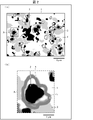
本発明の一実施形態におけるFe基焼結体について、図1~5を用いて説明すれば、以下のとおりである。なお、本実施形態におけるFe基焼結体の製造方法の詳細については後述する。図1は、本実施形態のFe基焼結体の組織について電子顕微鏡を用いて観察して得た反射電子像である。
<Fe-based sintered body>
The Fe-based sintered body according to the embodiment of the present invention will be described below with reference to FIGS. 1 to 5. The details of the method for producing the Fe-based sintered body in this embodiment will be described later. FIG. 1 is a backscattered electron image obtained by observing the structure of the Fe-based sintered body of the present embodiment using an electron microscope.
図1に示すように、本実施形態のFe基焼結体は、Feを主成分とするマトリックス(基地)1と、各種の相を含む分散相とを含有している。本実施形態のFe基焼結体は、概略的には、上述のようにFeとTiB2との混合粉末を、Cが供給される条件下で焼結することにより形成(製造)される。そのため、上記分散相は、原料であるTiB2を含む粒子状相(第1の副相)2と、TiB2とCとの反応により生成した微細なTiCを含有する硬質相4とを含む。また、上記分散相はさらに、Feと、TiB2から供給されたBとの反応によって生成したFe2Bを含有する副生成相(第2の副相)3を含む。
As shown in FIG. 1, the Fe-based sintered body of the present embodiment contains a matrix (base) 1 containing Fe as a main component and a dispersed phase containing various phases. The Fe-based sintered body of the present embodiment is generally formed (manufactured) by sintering a mixed powder of Fe and TiB 2 under conditions in which C is supplied, as described above. Therefore, the dispersed phase includes a particulate phase (first subphase) 2 containing TiB 2 , which is a raw material, and a
本実施形態のFe基焼結体の組織について、図2を用いてさらに詳細に説明する。図2の(a)は、図1に示す反射電子像の模式図である。図2の(b)は、上記模式図の一部を拡大して示す図である。なお、図2において、マトリックス1は濃淡が最も薄い(白色の)領域、粒子状相2は濃淡が最も濃い(黒色の)領域として示している。また、副生成相3はマトリックス1よりも少し濃淡が濃い(薄い灰色の)領域、硬質相4は副生成相3と粒子状相2の間の濃淡である(濃い灰色の)領域として示している。
The structure of the Fe-based sintered body of the present embodiment will be described in more detail with reference to FIG. FIG. 2A is a schematic diagram of the reflected electron image shown in FIG. FIG. 2B is an enlarged view showing a part of the schematic diagram. In FIG. 2, the
(マトリックス1)
図2の(a)に示すように、マトリックス1は、Fe基焼結体に占める割合が最も多い相であって、ネットワーク状に形成されている。マトリックス1は、例えばFe基焼結体全体を100重量部として、Fe基焼結体に占める割合が75質量%以上であることが好ましく、60質量%以上80質量%以下であることがより好ましい。また、マトリックス1は、Feを主成分とする相であって、マトリックス1におけるFeの濃度が99原子パーセント(以下、at%と記載する)以上であり、好ましくは99.9at%以上である。マトリックス1は、αFeを含む。マトリックス1は、好ましくは大部分がαFeからなる。
(Matrix 1)
As shown in FIG. 2A, the
ネットワーク状とは、例えば図2の(a)に示すように組織を平面視した場合(断面を観察した場合)、網目状に連続した相が形成されていることを意味する。マトリックス1の網目状構造における網の隙間に、粒子状相2、副生成相3、および硬質相4が島状に分散し、Fe基焼結体の島状複合組織を形成している。また、マトリックス1は多結晶であることから、ネットワーク状の構造中に結晶粒界が存在する。Fe基焼結体は、焼結により形成されていることから、マトリックス1に多少の空隙(ボイド)が存在してもよい。マトリックス1は、濃度分布があってもよく、複数の相を有していてもよい。このようなマトリックス1は、熱伝導性に優れている。
The network shape means that, for example, when the tissue is viewed in a plan view (when the cross section is observed) as shown in FIG. 2A, continuous phases are formed in a network shape. The particle-
なお、図2の(a)は組織を平面視した模式図であるが、実際上、マトリックス1は3次元空間においてネットワーク状構造を有している。本実施形態のFe基焼結体において、マトリックス1は、熱伝導に効果的な連続的なパス(熱伝導経路)として機能することができる。
Although FIG. 2A is a schematic view of the tissue in a plan view, the
また、マトリックス1は、セメンタイトの含有量が5質量%以下であってよく、好ましくは、1質量%以下である。マトリックス1は、αFeの含有量が70質量%以上であってよく、60質量%以上80質量%以下であってもよい。マトリックス1は、Cuの含有量が0.1質量%以下、およびSiの含有量が0.1質量%以下、の条件のうち少なくともいずれかを満たしていてもよく、その他の不純物が含まれていてもよい。ただし、このような不純物は、熱伝導率を低下させる、または炭化物の生成を促進する、といった作用を奏し得る。そのため、マトリックス1は、低い不純物含有量となるように製造されることが好ましい。
Further, the
(粒子状相2)
粒子状相2は、Fe基焼結体を製造する際に用いたTiB2粉末に由来する相である。焼結反応後に残存した一部のTiB2粉末が粒子状相2となる。そのため、Fe基焼結体における粒子状相2の存在割合は、焼結反応の条件によって変化する。それゆえ、粒子状相2の存在割合は特に限定されないが、例えば、粒子状相2は、例えばFe基焼結体に占める割合が10質量%以上であり、好ましくは15質量%以上20質量%以下である。粒子状相2は、マトリックス1よりも高い硬度を有していることから、Fe基焼結体の硬度を向上させる。
(Particulate phase 2)
The
(副生成相3)
副生成相3は、上述のように、Feと、TiB2から供給されたBとの反応によって生成したFe2Bを含有する相である。換言すれば、副生成相3は、焼結反応時に、TiCが生成する反応に伴ってTiB2が分解することにより、副生成物として生成したFe2Bを含有する相である。図2の(a)から、副生成相3は、原料のTiB2粉末が元々存在したであろう場所に形成されていることがわかる。また、同図から、副生成相3および粒子状相2の近傍に、後述する硬質相4が形成されていることがわかる。
(By-generation phase 3)
As described above, the by-produced
副生成相3は、マトリックス1よりも高い硬度を有していることから、Fe基焼結体の硬度を向上させる。
Since the by-produced
(硬質相4)
反射電子像の一部を拡大して示す図2の(b)を用いて、硬質相4について説明する。
(Hard phase 4)
The
図2の(b)に示すように、本実施形態における硬質相4は、特徴的な形状として、リング形状またはリング様形状を有している。本明細書において、リング形状またはリング様形状とは、完全な円形状のことだけでなく、図2の(b)に示す例のように歪んだ形の円形状(周方向に不規則に曲がった形状)をも含む意味で用いる。
As shown in FIG. 2B, the
また、硬質相4は、図2の(b)に示す例のように周方向の端部が無く連続した輪(閉じた円)であってもよく、一部が開放した輪であってもよい。つまり、硬質相4は一端から他端に向かって延びる形状であってもよい。
Further, the
硬質相4は、周方向に垂直な方向の幅Lが1.0μm以下であり、好ましくは0.4μm以下であり、より好ましくは0.2μm以上0.4μm以下である。上記幅Lは、以下のようにして測定することができる。すなわち、先ず、図2の(b)に示すように、例えば反射電子像における硬質相4の領域(濃い灰色の領域)と、他の相(例えばマトリックス1または副生成相3)の領域と、の境界を特定する。硬質相4の周方向に垂直な方向において、特定した上記境界に基づいて、硬質相4の幅Lを測定することができる。硬質相4は、マトリックス中に微細に分散した微細分散相ともいえる。
The width L of the
なお、硬質相4は、図2の(a)に示すように、様々な形状であってもよく、紐状形状を有していてもよい。紐状形状である場合、硬質相4は、長手方向(一端から他端に向かって延びる方向)に対して垂直な方向の幅Lが、上述の条件を満たしていればよい。
As shown in FIG. 2A, the
硬質相4は、硬度に非常に優れることが知られているTiCを含んでいる。そのため、本実施形態におけるFe基焼結体は、硬質相4を含むことにより、硬度を大きく向上させることができる。そして、上述のようにマトリックス1が熱伝導経路として機能する。その結果、本実施形態におけるFe基焼結体は、高い硬度と高い熱伝導率とを兼備することができる。
The
上記硬質相4は、焼結反応時に、圧粉体の周辺から内部へと拡散することにより供給されるCと、TiB2粉末とが微小領域にて非平衡反応することによって形成される。よって、例えば鋼の組織を制御して合金工具鋼を製造する場合よりも、本実施形態のFe基焼結体は安定的に製造可能である。
The
具体的には、本発明の一態様におけるFe基焼結体は、硬度が300HV(ビッカース硬さ)以上かつ熱伝導率が30W/(m・K)以上である。なお、300HV以上の硬度とは、ロックウェル硬さに概略的に換算して、30HRC以上と表現することもできる(換算式については後述)。 Specifically, the Fe-based sintered body according to one aspect of the present invention has a hardness of 300 HV (Vickers hardness) or more and a thermal conductivity of 30 W / (m · K) or more. The hardness of 300 HV or more can be expressed as 30 HRC or more by roughly converting it into Rockwell hardness (the conversion formula will be described later).
なお、Fe基焼結体は、外部に露出する表面部と、表面部よりも中心側に存在する内部との間で、硬度に差があってもよい。本発明の一態様におけるFe基焼結体は、後述するような焼結時の反応に基づいて、表面部の方が内部よりも硬度が高くなる傾向にある。本明細書において、格別の記載がない限り「硬度」とは表面部の硬度のことを意味する。Fe基焼結体の特性(材料特性)として重要となるのは、表面部の硬度である。 The hardness of the Fe-based sintered body may differ between the surface portion exposed to the outside and the inside existing on the center side of the surface portion. In the Fe-based sintered body according to one aspect of the present invention, the hardness of the surface portion tends to be higher than that of the inside portion based on the reaction at the time of sintering as described later. In the present specification, "hardness" means the hardness of the surface portion unless otherwise specified. What is important as a characteristic (material characteristic) of the Fe-based sintered body is the hardness of the surface portion.
本発明の一態様におけるFe基焼結体は、硬度が400HV(40HRC)以上であってよく、525HV(50HRC)以上であってもよい。 The Fe-based sintered body according to one aspect of the present invention may have a hardness of 400 HV (40 HRC) or more, and may be 525 HV (50 HRC) or more.
また、本発明の一態様におけるFe基焼結体は、熱伝導率が40W/(m・K)以上であってよく、45W/(m・K)以上であってもよく、50W/(m・K)以上であってもよい。本明細書において、格別の記載がない限り「熱伝導率」とは室温での熱伝導率のことを意味する。 Further, the Fe-based sintered body according to one aspect of the present invention may have a thermal conductivity of 40 W / (m · K) or more, 45 W / (m · K) or more, and 50 W / (m). -K) or higher may be used. In the present specification, unless otherwise specified, "thermal conductivity" means thermal conductivity at room temperature.
本発明の一態様におけるFe基焼結体は、硬度が525HV(50HRC)以上、かつ熱伝導率が40W/(m・K)以上である。 The Fe-based sintered body according to one aspect of the present invention has a hardness of 525 HV (50 HRC) or more and a thermal conductivity of 40 W / (m · K) or more.
<Fe基焼結体の製造方法>
以下に、本実施形態のFe基焼結体の製造方法について詳細に説明する。
<Manufacturing method of Fe-based sintered body>
Hereinafter, the method for producing the Fe-based sintered body of the present embodiment will be described in detail.
(原料)
Fe基焼結体の原料には、Feの微粉末とTiB2の微粉末とを用いる。これらの微粉末の形状は特に限定されないが、後述する粉末混合工程において均一に混合された混合粉末を得るために、微細な粉末であることが好ましい。例えば、Feの微粉末は、平均粒径が10μm以下であってよく、3μm以上5μm以下であることが好ましい。また、例えば、TiB2の微粉末は、平均粒径が5μm以下であってよく、2μm以上3μm以下であることが好ましい。
(material)
As the raw material of the Fe-based sintered body, a fine powder of Fe and a fine powder of TiB 2 are used. The shape of these fine powders is not particularly limited, but is preferably a fine powder in order to obtain a uniformly mixed powder in the powder mixing step described later. For example, the fine powder of Fe may have an average particle size of 10 μm or less, and preferably 3 μm or more and 5 μm or less. Further, for example, the fine powder of TiB 2 may have an average particle size of 5 μm or less, and preferably 2 μm or more and 3 μm or less.
Feの微粉末は、炭素濃度が0.1質量%以下の純鉄の微粉末であることが好ましい。TiB2の微粉末は、市販の標準的な純度のTiB2の微粉末であってよい。 The fine powder of Fe is preferably a fine powder of pure iron having a carbon concentration of 0.1% by mass or less. The TiB 2 fine powder may be a commercially available standard purity TiB 2 fine powder.
(成形工程)
成形工程において、先ず、Feの微粉末とTiB2の微粉末とを均一に混合する(混合工程)。この混合工程では、粉末を均一に混合することができればよく、その具体的な方法は特に限定されない。例えば、ボールミルを用いて粉末を混合してよく、遊星型ボールミルを用いることが好ましい。また、混合工程では、エタノール等を添加して湿式混合を行ってよく、乾式混合を行ってもよい。湿式混合を行った場合、使用したエタノール等を揮発させる乾燥工程を行う。乾燥工程における具体的な乾燥方法は特に限定されない。
(Molding process)
In the molding step, first, the fine powder of Fe and the fine powder of TiB 2 are uniformly mixed (mixing step). In this mixing step, it is sufficient that the powder can be uniformly mixed, and the specific method thereof is not particularly limited. For example, the powder may be mixed using a ball mill, and it is preferable to use a planetary ball mill. Further, in the mixing step, ethanol or the like may be added to perform wet mixing, or dry mixing may be performed. When wet mixing is performed, a drying step of volatilizing the used ethanol or the like is performed. The specific drying method in the drying step is not particularly limited.
次いで、成形工程では、Feの微粉末とTiB2の微粉末とを所望の割合(量比)で混合した混合粉末を成形(加圧成形)して成形体を得る。得られる成形体の密度や成形圧力は特に限定されない。なお、後述する焼結工程において、混合粉末を成形しつつ(成形工程を行いつつ)焼結を行うようになっていてもよい。 Next, in the molding step, a mixed powder obtained by mixing the fine powder of Fe and the fine powder of TiB 2 in a desired ratio (quantity ratio) is molded (pressure molding) to obtain a molded body. The density and molding pressure of the obtained molded product are not particularly limited. In the sintering step described later, sintering may be performed while molding the mixed powder (while performing the molding step).
(焼結工程)
本実施形態における焼結工程では、加圧しながら加熱することにより焼結を行う。このような焼結を行う方法としては、従来公知の固相焼結法を適宜選択して適用してよい。ただし、焼結条件(温度・圧力・雰囲気)については、上述のようなFe基焼結体が得られるように、適切に調整されることを要する。
(Sintering process)
In the sintering step in this embodiment, sintering is performed by heating while pressurizing. As a method for performing such sintering, a conventionally known solid-phase sintering method may be appropriately selected and applied. However, the sintering conditions (temperature, pressure, atmosphere) need to be appropriately adjusted so that the Fe-based sintered body as described above can be obtained.
焼結工程では、例えば、グラファイト製の加圧部材を用いて加圧を行う。これにより、焼結時に該加圧部材に由来するCが成形体内部に侵入する。そのため、焼結反応が生じる反応場にCが供給されて、TiB2とCとの反応により微小なTiCが生成する。 In the sintering step, for example, pressurization is performed using a pressurizing member made of graphite. As a result, C derived from the pressure member invades the inside of the molded body during sintering. Therefore, C is supplied to the reaction field where the sintering reaction occurs, and minute TiC is generated by the reaction between TiB 2 and C.
より詳しくは、焼結工程では、以下のような反応が生じる。すなわち、先ず、原料のTiB2微粉末の少なくとも一部を分解するとともに、Feの微粉末が互いに結合して、Feを主成分としてTiを含むネットワーク状のマトリックスを形成する。そして、TiB2微粉末に由来するTiと、上記加圧部材等に由来するC(Fe中に元々存在するCであってもよい)との反応により、マトリックス1中に微細分散したTiCが生成する。また、焼結温度は、マトリックスにαFeを含み、γFeが生成し難い温度とする。そして焼結工程において、CはTiCを生成することに主に消費される。これにより、セメンタイトの生成を抑制して、Fe基焼結体を製造することができる。本実施形態におけるFe基焼結体の製造方法は、このような反応が生じる焼結工程を含む。
More specifically, in the sintering process, the following reactions occur. That is, first, at least a part of the TiB 2 fine powder as a raw material is decomposed, and the fine powders of Fe are bonded to each other to form a network-like matrix containing Ti as a main component of Fe. Then, the reaction between Ti derived from the TiB 2 fine powder and C derived from the pressure member or the like (which may be C originally present in Fe) produces TiC finely dispersed in the
このような反応を生じさせるために、焼結工程では、1323K以上の温度、および15MPa以上の圧力の条件とする。上記温度は、焼結装置に設定される焼結温度であって、換言すれば焼結工程における最高到達温度である。上記温度は、好ましくは、1373K以上であり、より好ましくは1423K以上である。また、上記温度は、1323K以上1447K以下であることが好ましい。これは、FeとFe2Bとが反応して液相となることを回避するためである。また、上記圧力は、15MPa以上90MPa以下であることが好ましい。 In order to cause such a reaction, the sintering step is required to have a temperature of 1323 K or higher and a pressure of 15 MPa or higher. The above temperature is the sintering temperature set in the sintering apparatus, in other words, the maximum temperature reached in the sintering process. The temperature is preferably 1373 K or higher, more preferably 1423 K or higher. Further, the temperature is preferably 1323K or more and 1447K or less. This is to prevent Fe and Fe 2 B from reacting with each other to form a liquid phase. Further, the pressure is preferably 15 MPa or more and 90 MPa or less.
焼結工程において、昇温速度は特に限定されないが、例えば100K/minであってよい。最高到達温度において保持する時間(保持時間)は、略0秒であってよく、0秒より大きく600秒以下であってもよい。 In the sintering step, the rate of temperature rise is not particularly limited, but may be, for example, 100 K / min. The holding time (holding time) at the maximum reached temperature may be about 0 seconds, and may be larger than 0 seconds and 600 seconds or less.
また、焼結工程では、放電焼結法を用いることが好ましい。放電焼結法とは、型枠と該型枠の内部に充填された焼結材料(粉末)との間で通電を起こさせ、通電により発生する熱(ジュール熱)を用いて焼結反応を生じさせる方法である。放電焼結法に用いられる放電焼結機は、グラファイト製の円筒状の型およびグラファイト製のパンチにて焼結対象材料(成形体または粉末)を覆うようにして、パンチにより加圧しながら放電焼結を行う。放電焼結機は、パルス通電または連続通電することにより放電焼結を行ってよい。通電する電流は、焼結対象材料に臨界電圧以上が印加される条件とすればよい。このような放電焼結法を用いると、焼結対象材料の温度を均一に昇温することができ、均質かつ高品位なFe基焼結体を得ることができる。 Further, in the sintering step, it is preferable to use a discharge sintering method. In the electric discharge sintering method, an electric current is generated between a mold and a sintered material (powder) filled inside the mold, and the heat generated by the electric current (Joule heat) is used to perform a sintering reaction. It is a method to make it happen. The discharge sintering machine used in the discharge sintering method covers the material to be sintered (molded body or powder) with a cylindrical mold made of graphite and a punch made of graphite, and discharge firing while pressurizing with the punch. Make a conclusion. The discharge sintering machine may perform discharge sintering by pulse energization or continuous energization. The current to be energized may be a condition in which a critical voltage or higher is applied to the material to be sintered. By using such a discharge sintering method, the temperature of the material to be sintered can be uniformly raised, and a homogeneous and high-quality Fe-based sintered body can be obtained.
ここで、一般に、Feのような金属をベースとする焼結体を作製するために放電焼結を行う場合、1000K程度の温度とすれば充分に焼結反応が進行すると考えられる。しかし、本実施形態のFe基焼結体は、焼結温度が1000K程度で有る場合、TiCの硬質相4が生成しないため得ることができない。本発明者らは、鋭意検討の結果、上述の焼結条件(すなわち、1323K以上の温度、および15MPa以上の圧力)とすることによって、機構は完全には明らかではないが、TiCを含む硬質相4が生成してFe基焼結体の硬度が向上することを見出し、その知見に基づいて本発明を想到した。
Here, in general, when discharge sintering is performed to produce a sintered body based on a metal such as Fe, it is considered that the sintering reaction proceeds sufficiently at a temperature of about 1000 K. However, the Fe-based sintered body of the present embodiment cannot be obtained when the sintering temperature is about 1000 K because the
なお、焼結工程において、パンチ等の材質がグラファイト製でなくてもよく、その場合、成形体の表面にグラファイトをコーティングした、またはCを含浸した後に焼結を行うようになっていてもよい。また、成形体の表面に炭素粉末を付着させた状態にて焼結を行ってもよい。 In the sintering step, the material such as the punch does not have to be made of graphite, and in that case, the surface of the molded product may be coated with graphite or impregnated with C before sintering. .. Further, sintering may be performed with the carbon powder adhered to the surface of the molded product.
上記のような放電焼結法は、操作が比較的容易であり、焼結時の温度および圧力を比較的安定に制御することができる。そのため、Fe基焼結体を安定的に製造し易い。 The discharge sintering method as described above is relatively easy to operate, and the temperature and pressure at the time of sintering can be controlled relatively stably. Therefore, it is easy to stably manufacture the Fe-based sintered body.
(後工程)
Fe基焼結体の製造方法は、焼結工程の後、焼結体の表面を研磨および洗浄する工程を含んでいてもよい。
(Post-process)
The method for producing an Fe-based sintered body may include a step of polishing and cleaning the surface of the sintered body after the sintering step.
以上のような工程により製造した本発明の一態様におけるFe基焼結体の、表面および断面を観察した結果の一例を図3に示す。図3は、本発明の一実施形態におけるFe基焼結体の、組織を観察可能となるように研磨した試料を観察することにより得た反射電子像であり、(a)は試料表面、(b)は試料断面を観察した反射電子像である。 FIG. 3 shows an example of the results of observing the surface and cross section of the Fe-based sintered body according to one aspect of the present invention manufactured by the above steps. FIG. 3 is a backscattered electron image obtained by observing a sample of the Fe-based sintered body according to the embodiment of the present invention, which has been polished so that the structure can be observed. FIG. 3A is a sample surface, (a). b) is a backscattered electron image obtained by observing the cross section of the sample.
図3の(a)および(b)に示すように、Fe基焼結体は、上述したような島状複合組織(図2参照)が形成されていることがわかる。Fe基焼結体の内部(試料断面)においても、硬質相4が形成していることがわかる。
As shown in FIGS. 3A and 3B, it can be seen that the Fe-based sintered body has an island-like composite structure (see FIG. 2) as described above. It can be seen that the
(熱間プレス用金型)
なお、本実施形態のFe基焼結体は、熱間プレス用金型の製造に用いられてよく、本実施形態のFe基焼結体を用いて製造された熱間プレス用金型も本発明の範疇に含まれる。
(Mold for hot pressing)
The Fe-based sintered body of the present embodiment may be used for manufacturing a hot pressing die, and a hot pressing die manufactured by using the Fe-based sintered body of the present embodiment is also used. It is included in the category of invention.
(変形例)
本発明の一態様におけるFe基焼結体の製造方法では、成形工程と後述する焼結工程との間に仮焼工程が含まれてもよく、含まれていなくともよい。仮焼工程を含む場合、Feの微粉末とTiB2の微粉末とに、微細な炭素粒子を加えて混合し、得られた混合粉末を成形して成形体を得る。そして、該成形体を用いて仮焼工程を行う。これにより、本発明の一態様におけるFe基焼結体を製造してもよい。
(Modification example)
In the method for producing an Fe-based sintered body according to one aspect of the present invention, a calcining step may or may not be included between the molding step and the sintering step described later. When the calcination step is included, fine carbon particles are added to the fine powder of Fe and the fine powder of TiB 2 and mixed, and the obtained mixed powder is molded to obtain a molded product. Then, a calcining step is performed using the molded body. Thereby, the Fe-based sintered body according to one aspect of the present invention may be produced.
以下、実施例および比較例により、本発明の一態様におけるFe基焼結体についてさらに詳しく説明するが、本発明はこれら実施例に限定されるものではない。 Hereinafter, the Fe-based sintered body according to one embodiment of the present invention will be described in more detail with reference to Examples and Comparative Examples, but the present invention is not limited to these Examples.
〔第1の実施例〕
(試料作製)
平均粒径3~5μmの純Feの微粉末と、平均粒径2~3μmのTiB2の微粉末とを、遊星型ボールミルを用いて、100rpmで1時間乾式混合した。純Fe:TiB2の比率は、質量比で80:20(体積比で70:30)とした。遊星型ボールミルの容器内には、混合粉末15gに対してセラミックス球(ボール)を150gの割合で投入して混合を行った。
[First Example]
(Sample preparation)
A fine powder of pure Fe having an average particle size of 3 to 5 μm and a fine powder of TiB 2 having an average particle size of 2 to 3 μm were dry-mixed at 100 rpm for 1 hour using a planetary ball mill. The ratio of pure Fe: TiB 2 was 80:20 in terms of mass ratio (70:30 in volume ratio). In the container of the planetary ball mill, ceramic balls (balls) were charged at a ratio of 150 g to 15 g of the mixed powder and mixed.
上記乾式混合の後、遊星型ボールミルの容器内にエタノールを15~20ml添加して、3時間湿式混合を行った。湿式混合の後、得られたスラリーを自然乾燥させて、混合粉末を得た。 After the above dry mixing, 15 to 20 ml of ethanol was added into the container of the planetary ball mill, and wet mixing was performed for 3 hours. After wet mixing, the obtained slurry was air-dried to obtain a mixed powder.
得られた混合粉末を放電焼結機のグラファイト製の型枠内に充填した。グラファイト製のパンチを用いて加圧しながら、加熱するとともに通電し、放電焼結を行った。焼結温度(最大到達温度)は1273K~1423Kとし、加圧圧力は50MPaとした。昇温速度は100k/minとし、保持時間は略0秒とした。 The obtained mixed powder was filled in a graphite mold of a discharge sintering machine. While pressurizing with a graphite punch, heating and energization were performed to perform discharge sintering. The sintering temperature (maximum ultimate temperature) was 1273K to 1423K, and the pressurizing pressure was 50 MPa. The rate of temperature rise was 100 k / min, and the holding time was approximately 0 seconds.
焼結後、放電焼結機から試料を取り出して、研磨を行った後、X線回折測定、電子顕微鏡観察、熱伝導率測定、密度測定、および硬度試験を行った。 After sintering, the sample was taken out from the discharge sintering machine and polished, and then X-ray diffraction measurement, electron microscope observation, thermal conductivity measurement, density measurement, and hardness test were performed.
(X線回折測定)
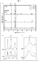
試料を粉砕して粉末試料とし、該粉末試料を用いて粉末X線回折測定を行った。照射X線としては、CuのKα線を用いた。測定結果を図4に示す。図4の(a)は、焼結温度が1273K~1423Kの条件で作製した粉末試料を、X線回折装置を用いて粉末X線回折測定して得られるX線回折パターンの一例を示す図であり、(b)は、上記X線回折パターンにおける回折角2θが35°前後について拡大して示す図であり、(c)は、上記X線回折パターンにおける回折角2θが45°前後を拡大して示す図である。
(X-ray diffraction measurement)
The sample was pulverized into a powder sample, and the powder X-ray diffraction measurement was performed using the powder sample. Cu Kα rays were used as the irradiation X-rays. The measurement results are shown in FIG. FIG. 4A is a diagram showing an example of an X-ray diffraction pattern obtained by powder X-ray diffraction measurement of a powder sample prepared under the condition of a sintering temperature of 1273K to 1423K using an X-ray diffractometer. Yes, (b) is a diagram showing an enlarged diffraction angle 2θ in the X-ray diffraction pattern around 35 °, and (c) is a diagram in which the diffraction angle 2θ in the X-ray diffraction pattern is enlarged around 45 °. It is a figure which shows.
図4において、○印はTiB2、△印はαFe、□印はFe2B、◇印はTiCの回折ピークにそれぞれ対応している。図4の(b)に示すように、焼結温度が1273Kの試料ではTiCおよびFe2Bの明瞭なピークが見られず、TiCが生成していない。一方で、焼結温度が1323K、1373K、1423Kの試料では、TiCおよびFe2Bの明瞭な回折ピークが観測された。また、焼結温度が1323K、1373K、1423Kの試料でFe2Bの回折ピークが観測されることは、図4の(c)に示す回折パターンからもわかる。 In FIG. 4, ○ marks correspond to TiB 2 , Δ marks correspond to αFe, □ marks correspond to Fe 2 B, and ◇ marks correspond to TiC diffraction peaks. As shown in FIG. 4 ( b ), no clear peaks of TiC and Fe 2B were observed in the sample having a sintering temperature of 1273 K, and TiC was not generated. On the other hand, in the samples with sintering temperatures of 1323K, 1373K and 1423K , clear diffraction peaks of TiC and Fe 2B were observed. Further, it can be seen from the diffraction pattern shown in FIG. 4 (c) that the diffraction peak of Fe 2B is observed in the samples having the sintering temperatures of 1323K , 1373K and 1423K.
(電子顕微鏡観察)
各試料について、試料表面および試料断面の電子顕微鏡観察を行った。試料表面とは、放電焼結時にグラファイト製のパンチに接していた部分を研磨して表れた表面である。試料断面とは、Fe基焼結体の内部の部分であって、焼結後の焼結体を切断して、断面を研磨して表れた表面である。
(Electron microscope observation)
For each sample, electron microscopic observation of the sample surface and the sample cross section was performed. The sample surface is a surface that appears by polishing a portion that was in contact with a graphite punch during discharge sintering. The sample cross section is an internal portion of the Fe-based sintered body, and is a surface obtained by cutting the sintered body after sintering and polishing the cross section.
試料表面および試料断面について、反射電子像を撮像するとともに、波長分散型X線分析(WDX)により組成分析を行った。また、WDXにより、試料表面および試料断面についてTiB2の濃度を測定した。その結果、試料表面および試料断面のいずれにおいても、焼結温度が高くなるほどTiB2の濃度が減少していた(後述の図6参照)。 The surface of the sample and the cross section of the sample were imaged with a backscattered electron image, and the composition was analyzed by wavelength dispersive X-ray analysis (WDX). In addition, the concentration of TiB 2 was measured on the sample surface and the sample cross section by WDX. As a result, the concentration of TiB 2 decreased as the sintering temperature increased on both the sample surface and the sample cross section (see FIG. 6 described later).
また、焼結温度が1373Kの試料について、試料表面の局所的なWDXを行った。結果を図5に示す。図5の(a)は、試料の反射電子像における、局所的なWDXを行った箇所を示す図である。図5の(b)は、WDXを行った8箇所の組成分析結果を示す図である。 Further, for a sample having a sintering temperature of 1373 K, local WDX on the sample surface was performed. The results are shown in FIG. FIG. 5A is a diagram showing a location where local WDX was performed in the backscattered electron image of the sample. FIG. 5B is a diagram showing the results of composition analysis at eight locations where WDX was performed.
図5の(a)および(b)に示すように、リング状の硬質相4が観察される(1)~(3)の箇所では、Feを主成分とするマトリックス1とともにTiCが存在することがわかる。また、濃淡が濃い(黒色の)粒子状相2が観察される(4)および(5)の箇所では、TiB2が存在することがわかる。そして、副生成相3が観察される(6)および(7)の箇所ではFe2Bが存在し、マトリックス1が観察される(8)の箇所ではほぼ全てFeであることが分かる。
As shown in FIGS. 5A and 5B, TiC is present together with the
(熱伝導率測定、密度測定、硬度試験)
熱伝導率測定は、定常法(被測定試料に定常的な温度勾配を与え、熱伝導率を測定する方法)を用いて行った。つまり、被測定試料の片方を高温にし、もう一方を低温にし、試料内の各点の温度を測定して熱伝導率を求めた。
(Measurement of thermal conductivity, density measurement, hardness test)
The thermal conductivity was measured by using a steady method (a method of giving a steady temperature gradient to a sample to be measured and measuring the thermal conductivity). That is, one of the samples to be measured was heated to a high temperature and the other to a low temperature, and the temperature of each point in the sample was measured to obtain the thermal conductivity.
密度測定は、アルキメデス法を用いて行った。相対密度は、アルキメデス法で測定した密度を、理論密度にて除することにより求めた。 Density measurements were performed using the Archimedes method. The relative density was determined by dividing the density measured by the Archimedes method by the theoretical density.
硬度試験は、試料表面および試料内部について、それぞれビッカース硬さ試験により行った。試験力を30kgとし、保持時間を10秒とした。 The hardness test was performed by the Vickers hardness test on the surface of the sample and the inside of the sample, respectively. The test force was 30 kg and the holding time was 10 seconds.
(結果)
上述した試験の結果をまとめ、図6に示す。なお、熱伝導率およびビッカース硬さは、複数の測定を行った誤差を含めて示している。該誤差は、標準偏差である。
(result)
The results of the above tests are summarized and shown in FIG. The thermal conductivity and Vickers hardness are shown including errors in multiple measurements. The error is the standard deviation.
なお、ビッカース硬さ(HV)は、以下の変換式を用いてロックウェル硬さ(HRC)に換算することができる。 The Vickers hardness (HV) can be converted into Rockwell hardness (HRC) using the following conversion formula.
(i)520HV以上の場合;
HRC=(100×HV-15100)/(HV+223)
(ii)200HV以上520HV未満の場合;
HRC=(100×HV-13700)/(HV+223)。
(I) In the case of 520 HV or more;
HRC = (100 x HV-15100) / (HV + 223)
(Ii) When 200 HV or more and less than 520 HV;
HRC = (100 × HV-13700) / (HV + 223).
焼結温度が1273Kである比較例1では、熱伝導率が44W/(m・K)程度であり、ビッカース硬さが220HV程度である。比較例1の試料は、組織にTiCが生成しておらず、硬度を高める硬質相4が存在しない。そのため、比較例1の試料は、マトリックス1による熱伝導によって高い熱伝導率を示す一方で、硬度は不十分である。
In Comparative Example 1 in which the sintering temperature is 1273 K, the thermal conductivity is about 44 W / (m · K) and the Vickers hardness is about 220 HV. In the sample of Comparative Example 1, TiC was not generated in the structure, and the
これに対して、焼結温度が1323K~1423Kである実施例1~3では、焼結温度が高くなるほど、硬度が向上していることがわかる。熱伝導率については、実施例1および実施例2は比較例1よりも少し劣る。この理由については明らかでないが、マトリックス1中にTiおよびCが固溶することが一因であり得ると推察される。焼結温度が高いほど、TiおよびCの拡散が促進され、TiCを形成し易い。
On the other hand, in Examples 1 to 3 in which the sintering temperature is 1323K to 1423K, it can be seen that the higher the sintering temperature, the higher the hardness. In terms of thermal conductivity, Example 1 and Example 2 are slightly inferior to Comparative Example 1. The reason for this is not clear, but it is speculated that it may be due to the solid solution of Ti and C in
また、実施例1~3の結果から、焼結温度が高くなるほど、試料表面および試料内部のTiB2濃度が低下することもわかる。焼結後のTiB2濃度の低下量が大きいほど、TiCの生成量は大きくなると考えられる。また、焼結温度が高くなるほど、密度および相対密度が増大した。 Further, from the results of Examples 1 to 3, it can be seen that the higher the sintering temperature, the lower the TiB 2 concentration on the sample surface and inside the sample. It is considered that the larger the decrease in TiB 2 concentration after sintering, the larger the amount of TiC produced. Also, the higher the sintering temperature, the higher the density and relative density.
本実施例から、本発明の一態様によれば、高い硬度と高い熱伝導率とを兼備するFe基焼結体を、より安定して製造できることがわかる。 From this example, it can be seen that according to one aspect of the present invention, an Fe-based sintered body having both high hardness and high thermal conductivity can be produced more stably.
〔第2の実施例〕
前記第1の実施例では、保持時間を略0秒として、焼結温度を1273K~1423Kに変化させて試料を作製していた。これに対し、本実施例では、焼結温度を1373Kとし、保持時間を略0秒、300秒、600秒と変化させて試料を作製した。
[Second Example]
In the first embodiment, the sample was prepared by changing the sintering temperature from 1273K to 1423K with the holding time set to about 0 seconds. On the other hand, in this example, a sample was prepared by setting the sintering temperature to 1373 K and changing the holding time to about 0 seconds, 300 seconds, and 600 seconds.
焼結温度を1373Kとし、保持時間を略0秒、300秒、600秒としたこと以外は、前述した第1の実施例と同様の条件により試料を作製した。また、前述した第1の実施例と同様の方法にて各種試験を行った。 A sample was prepared under the same conditions as in the first embodiment described above, except that the sintering temperature was 1373 K and the holding times were approximately 0 seconds, 300 seconds, and 600 seconds. In addition, various tests were performed by the same method as in the first embodiment described above.
X線回折測定を行った結果を図7に示す。図7の(a)は、焼結温度が1373K、保持時間が略0秒~600秒の条件で作製した粉末試料を、X線回折装置を用いて粉末X線回折測定して得られるX線回折パターンの一例を示す図であり、(b)は、上記X線回折パターンにおける回折角2θが35°前後について拡大して示す図であり、(c)は、上記X線回折パターンにおける回折角2θが45°前後を拡大して示す図である。 The result of the X-ray diffraction measurement is shown in FIG. FIG. 7A shows X-rays obtained by measuring powder X-ray diffraction using an X-ray diffractometer on a powder sample prepared under the conditions of a sintering temperature of 1373 K and a holding time of approximately 0 to 600 seconds. It is a figure which shows an example of the diffraction pattern, (b) is the figure which magnifies the diffraction angle 2θ in the said X-ray diffraction pattern about 35 °, and (c) is the figure which shows the diffraction angle in the said X-ray diffraction pattern. It is a figure which magnifies 2θ around 45 °.
図7において、各種の印と物質との対応関係は図4にて前述したことと同様である。図7の(b)に示すように、保持時間が長くなるについて、TiCの回折ピークの強度が増大した。また、図7の(c)に示すように、保持時間が長くなるについて、Fe2Bの回折ピークの強度が増大した。 In FIG. 7, the correspondence between various marks and substances is the same as described above in FIG. As shown in FIG. 7 (b), the intensity of the diffraction peak of TiC increased as the holding time increased. Further, as shown in FIG. 7 (c), the intensity of the diffraction peak of Fe 2 B increased as the holding time increased.
各種の試験の結果をまとめ、図8に示す。なお、熱伝導率およびビッカース硬さは、複数の測定を行った誤差を含めて示している。 The results of various tests are summarized and shown in FIG. The thermal conductivity and Vickers hardness are shown including errors in multiple measurements.
保持時間がそれぞれ略0秒、300秒、600秒である実施例4~6の結果から、保持時間が長くなるほど、熱伝導率および硬度が有意に向上することがわかる。また、保持時間が長くなるほど、密度および相対密度も増大した。 From the results of Examples 4 to 6 in which the holding times are approximately 0 seconds, 300 seconds, and 600 seconds, respectively, it can be seen that the longer the holding time, the more the thermal conductivity and the hardness are significantly improved. Also, the longer the retention time, the higher the density and relative density.
以上のように、本発明の一態様におけるFe基焼結体は、焼結温度を高くすること、および保持時間を長くすることによって、熱伝導率および硬度を向上させることができる。換言すれば、焼結条件を制御することによって、比較的簡便に、熱伝導率および硬度を制御することができる。それゆえ、本発明の一態様によれば、高い硬度と高い熱伝導率とを兼備するFe基焼結体を、より安定して製造できることがわかる。 As described above, the Fe-based sintered body according to one aspect of the present invention can improve the thermal conductivity and hardness by raising the sintering temperature and lengthening the holding time. In other words, by controlling the sintering conditions, the thermal conductivity and hardness can be controlled relatively easily. Therefore, according to one aspect of the present invention, it can be seen that an Fe-based sintered body having both high hardness and high thermal conductivity can be produced more stably.
〔第3の実施例〕
前記第1および第2の実施例では、純Fe:TiB2の比率を質量比で80:20として試料を作製していた。これに対し、本実施例では、純Fe:TiB2の比率を質量比で87:13として試料を作製した(実施例7)。また、焼結温度を1373Kとし、保持時間を600秒とした。それ以外は、前述した第1の実施例と同様の条件により試料を作製した。また、前述した第1の実施例と同様の方法にて各種試験を行った。
[Third Example]
In the first and second examples, the sample was prepared by setting the ratio of pure Fe: TiB 2 to 80:20 by mass. On the other hand, in this example, a sample was prepared by setting the ratio of pure Fe: TiB 2 to 87:13 by mass ratio (Example 7). Further, the sintering temperature was set to 1373K and the holding time was set to 600 seconds. Other than that, a sample was prepared under the same conditions as in the first embodiment described above. In addition, various tests were performed by the same method as in the first embodiment described above.
得られた結果を図9に示す。図9の(a)は、作製した試料の組織について電子顕微鏡を用いて観察して得た反射電子像である。図9の(b)は、該試料の試験結果をまとめて示す表である。 The obtained results are shown in FIG. FIG. 9A is a reflected electron image obtained by observing the structure of the prepared sample using an electron microscope. FIG. 9B is a table showing the test results of the sample collectively.
図9の(a)に示すように、本実施例の試料は、前記第1および第2の実施例と同様に、マトリックス1、粒子状相2、副生成相3および硬質相4を有している。そして、図9の(b)に示すように、本実施例の条件においても、高い硬度と高い熱伝導率とを兼備するFe基焼結体を得られる。
As shown in FIG. 9A, the sample of this example has a
なお、本実施例と、前記第2の実施例における実施例6(図8参照)とを比較すると、以下のことがわかる。すなわち、仕込みのTiB2の量が多いと、硬度および熱伝導率が向上する。そのため、本発明の一態様におけるFe基焼結体は、仕込みの原料比(純Fe:TiB2の比率)を制御することによって、比較的簡便に、熱伝導率および硬度を制御することができる。それゆえ、本発明の一態様によれば、高い硬度と高い熱伝導率とを兼備するFe基焼結体を、より安定して製造できることがわかる。 Comparing this example with Example 6 (see FIG. 8) in the second example, the following can be seen. That is, when the amount of TiB 2 charged is large, the hardness and thermal conductivity are improved. Therefore, in the Fe-based sintered body according to one aspect of the present invention, the thermal conductivity and hardness can be controlled relatively easily by controlling the raw material ratio (ratio of pure Fe: TiB 2 ) to be charged. .. Therefore, according to one aspect of the present invention, it can be seen that an Fe-based sintered body having both high hardness and high thermal conductivity can be produced more stably.
本発明は上述した実施形態に限定されるものではなく、請求項に示した範囲で種々の変更が可能であり、上記説明において開示された技術的手段を適宜組み合わせて得られる実施形態についても本発明の技術的範囲に含まれる。 The present invention is not limited to the above-described embodiment, and various modifications can be made within the scope of the claims, and the present invention also relates to an embodiment obtained by appropriately combining the technical means disclosed in the above description. It is included in the technical scope of the invention.
1 マトリックス
2 粒子状相(第1の副相)
3 副生成相(第2の副相)
4 硬質相
1
3 By-generation phase (second sub-phase)
4 Hard phase
Claims (8)
前記マトリックスは、ネットワーク状に形成されているとともに、αFeを含んでおり、
前記分散相は、TiCを含み、
前記分散相は、前記TiCを含有する、リング形状若しくはリング様形状の硬質相を含むことを特徴とするFe基焼結体。 An Fe-based sintered body having a matrix containing Fe as a main component and a dispersed phase dispersed in the matrix.
The matrix is formed in a network shape and contains αFe.
The dispersed phase contains TiC.
The dispersed phase is an Fe-based sintered body containing the TiC and containing a ring-shaped or ring-like hard phase .
前記マトリックスは、ネットワーク状に形成されているとともに、αFeを含んでおり、
前記分散相は、TiCを含み、
前記分散相は、前記TiCを含有する、長手方向に対して垂直な方向における幅が1.0μm以下の硬質相を含むことを特徴とするFe基焼結体。 An Fe-based sintered body having a matrix containing Fe as a main component and a dispersed phase dispersed in the matrix.
The matrix is formed in a network shape and contains αFe.
The dispersed phase contains TiC.
The dispersed phase is a Fe-based sintered body containing the TiC and containing a hard phase having a width of 1.0 μm or less in a direction perpendicular to the longitudinal direction.
前記マトリックスは、ネットワーク状に形成されているとともに、αFeを含んでおり、
前記分散相は、TiCを含み、
前記分散相は、TiB2を含有する第1の副相およびFe2Bを含有する第2の副相をさらに含むことを特徴とするFe基焼結体。 An Fe-based sintered body having a matrix containing Fe as a main component and a dispersed phase dispersed in the matrix.
The matrix is formed in a network shape and contains αFe.
The dispersed phase contains TiC.
The dispersed phase is a Fe-based sintered body further containing a first subphase containing TiB 2 and a second subphase containing Fe 2B.
前記マトリックスは、ネットワーク状に形成されているとともに、αFeを含んでおり、
前記分散相は、TiCを含み、
硬度が50HRC以上、かつ熱伝導率が40W/(m・K)以上であることを特徴とするFe基焼結体。 An Fe-based sintered body having a matrix containing Fe as a main component and a dispersed phase dispersed in the matrix.
The matrix is formed in a network shape and contains αFe.
The dispersed phase contains TiC.
A Fe-based sintered body having a hardness of 50 HRC or more and a thermal conductivity of 40 W / (m · K) or more.
前記焼結工程では、
15MPa以上の圧力で加圧し、1323K以上の温度で加熱することにより、前記TiB2の少なくとも一部を分解するとともに、Feを主成分としてTiを含むネットワーク状のマトリックスを形成し、
前記マトリックスはαFeを含み、
前記TiB2に由来するTiと前記加圧部材に由来するCとの反応により、前記マトリックス中に分散したTiCを生成させるように焼結することを特徴とするFe基焼結体の製造方法。 It includes a sintering step of heating and sintering a molded body obtained by pressure-molding a mixed powder containing Fe powder and TiB 2 powder while applying pressure using a pressure member made of graphite.
In the sintering process,
By pressurizing at a pressure of 15 MPa or more and heating at a temperature of 1323 K or more, at least a part of the TiB 2 is decomposed, and a network-like matrix containing Ti as a main component is formed.
The matrix contains αFe and contains
A method for producing an Fe-based sintered body, which comprises sintering so as to generate TiC dispersed in the matrix by a reaction between Ti derived from TiB 2 and C derived from the pressure member.
Priority Applications (5)
| Application Number | Priority Date | Filing Date | Title |
|---|---|---|---|
| JP2018148885A JP7100320B2 (en) | 2018-08-07 | 2018-08-07 | Fe-based sintered body, manufacturing method of Fe-based sintered body, and hot pressing die |
| PCT/JP2019/029057 WO2020031702A1 (en) | 2018-08-07 | 2019-07-24 | Fe-based sintered body, fe-based sintered body production method, and hot-pressing die |
| US17/266,375 US11858045B2 (en) | 2018-08-07 | 2019-07-24 | Fe-based sintered body, Fe-based sintered body production method, and hot-pressing die |
| CN201980052043.5A CN112567060B (en) | 2018-08-07 | 2019-07-24 | Fe-based sintered body, method for producing Fe-based sintered body, and mold for hot pressing |
| EP19846080.0A EP3835443A4 (en) | 2018-08-07 | 2019-07-24 | FE-BASED SINTERED BODY, FE-BASED SINTERED BODY PRODUCTION METHOD AND HOT PRESSING DIE |
Applications Claiming Priority (1)
| Application Number | Priority Date | Filing Date | Title |
|---|---|---|---|
| JP2018148885A JP7100320B2 (en) | 2018-08-07 | 2018-08-07 | Fe-based sintered body, manufacturing method of Fe-based sintered body, and hot pressing die |
Publications (2)
| Publication Number | Publication Date |
|---|---|
| JP2020023733A JP2020023733A (en) | 2020-02-13 |
| JP7100320B2 true JP7100320B2 (en) | 2022-07-13 |
Family
ID=69414805
Family Applications (1)
| Application Number | Title | Priority Date | Filing Date |
|---|---|---|---|
| JP2018148885A Active JP7100320B2 (en) | 2018-08-07 | 2018-08-07 | Fe-based sintered body, manufacturing method of Fe-based sintered body, and hot pressing die |
Country Status (5)
| Country | Link |
|---|---|
| US (1) | US11858045B2 (en) |
| EP (1) | EP3835443A4 (en) |
| JP (1) | JP7100320B2 (en) |
| CN (1) | CN112567060B (en) |
| WO (1) | WO2020031702A1 (en) |
Families Citing this family (1)
| Publication number | Priority date | Publication date | Assignee | Title |
|---|---|---|---|---|
| CN114974731B (en) * | 2022-05-13 | 2025-09-30 | 合肥工业大学 | A nano-Fe3C particle composite carbon-based conductive film and its preparation method |
Citations (2)
| Publication number | Priority date | Publication date | Assignee | Title |
|---|---|---|---|---|
| JP2000273503A (en) | 1999-03-25 | 2000-10-03 | Kobe Steel Ltd | Hard particle-dispersed sintered steel and its production |
| JP2018053308A (en) | 2016-09-28 | 2018-04-05 | マツダ株式会社 | Copper-containing ferrous sintered alloy for die-casting die, method for producing the same, and die-casting die produced using copper-containing ferrous sintered alloy for die-casting die |
Family Cites Families (16)
| Publication number | Priority date | Publication date | Assignee | Title |
|---|---|---|---|---|
| BE791741Q (en) * | 1970-01-05 | 1973-03-16 | Deutsche Edelstahlwerke Ag | |
| JPS5020947B1 (en) * | 1970-01-19 | 1975-07-18 | ||
| JPS4829965B1 (en) * | 1970-12-28 | 1973-09-14 | ||
| US3796111A (en) | 1971-08-18 | 1974-03-12 | Sundstrand Corp | Hydromechanical multi-range transmission |
| DE2244470C3 (en) * | 1972-09-11 | 1975-03-13 | Deutsche Edelstahlwerke Ag, 4150 Krefeld | Highly corrosion-resistant and wear-resistant sintered steel alloy |
| US3809540A (en) | 1972-12-29 | 1974-05-07 | Chromalloy American Corp | Sintered steel bonded titanium carbide tool steel characterized by an improved combination of transverse rupture strength and resistance to thermal shock |
| US3999952A (en) * | 1975-02-28 | 1976-12-28 | Toyo Kohan Co., Ltd. | Sintered hard alloy of multiple boride containing iron |
| KR920007849B1 (en) * | 1984-03-12 | 1992-09-18 | 제네랄 일렉트릭 캄파니 | Element resistant to solid particle erosion utilizing titanium carbide |
| US4704336A (en) * | 1984-03-12 | 1987-11-03 | General Electric Company | Solid particle erosion resistant coating utilizing titanium carbide |
| JPS62177159A (en) * | 1986-01-30 | 1987-08-04 | Mazda Motor Corp | Sintered alloy member having excellent wear resistance |
| JPH02263947A (en) * | 1989-04-03 | 1990-10-26 | Tokushu Denkyoku Kk | Manufacture of high strength steel containing dispersed carbide |
| JP3032818B2 (en) * | 1998-05-11 | 2000-04-17 | 工業技術院長 | Titanium boride dispersed hard material |
| DE19944592A1 (en) * | 1999-09-16 | 2001-03-22 | Hans Berns | Process for the powder-metallurgical in-situ production of a wear-resistant composite material |
| EP1887096A1 (en) | 2006-08-09 | 2008-02-13 | Rovalma, S.A. | Hot working steel |
| CN100494443C (en) * | 2007-08-07 | 2009-06-03 | 广西大学 | TiCp/Fe Composite Materials Prepared by In-Situ Reaction Casting Method by Adding Titanium at Low Temperature |
| CN101525716B (en) * | 2009-04-21 | 2011-04-20 | 合肥工业大学 | Iron aluminide intermetallic compound-titanium diboride composite material and preparation method thereof |
-
2018
- 2018-08-07 JP JP2018148885A patent/JP7100320B2/en active Active
-
2019
- 2019-07-24 EP EP19846080.0A patent/EP3835443A4/en active Pending
- 2019-07-24 CN CN201980052043.5A patent/CN112567060B/en active Active
- 2019-07-24 US US17/266,375 patent/US11858045B2/en active Active
- 2019-07-24 WO PCT/JP2019/029057 patent/WO2020031702A1/en not_active Ceased
Patent Citations (2)
| Publication number | Priority date | Publication date | Assignee | Title |
|---|---|---|---|---|
| JP2000273503A (en) | 1999-03-25 | 2000-10-03 | Kobe Steel Ltd | Hard particle-dispersed sintered steel and its production |
| JP2018053308A (en) | 2016-09-28 | 2018-04-05 | マツダ株式会社 | Copper-containing ferrous sintered alloy for die-casting die, method for producing the same, and die-casting die produced using copper-containing ferrous sintered alloy for die-casting die |
Also Published As
| Publication number | Publication date |
|---|---|
| US11858045B2 (en) | 2024-01-02 |
| CN112567060A (en) | 2021-03-26 |
| JP2020023733A (en) | 2020-02-13 |
| EP3835443A1 (en) | 2021-06-16 |
| EP3835443A4 (en) | 2022-07-20 |
| CN112567060B (en) | 2022-04-12 |
| WO2020031702A1 (en) | 2020-02-13 |
| US20210308756A1 (en) | 2021-10-07 |
Similar Documents
| Publication | Publication Date | Title |
|---|---|---|
| Kim et al. | Consolidation and properties of binderless sub-micron tungsten carbide by field-activated sintering | |
| Herranz et al. | Processing of AISI M2 high speed steel reinforced with vanadium carbide by solar sintering | |
| DE4340652A1 (en) | A composite material for machine tool cutting blades | |
| Várez et al. | Sintering in different atmospheres of T15 and M2 high speed steels produced by a modified metal injection moulding process | |
| Panov | Nanostructured sintered WC–Co hard metals | |
| US20140178139A1 (en) | Method of manufacturing super hard alloy containing carbon nanotubes, super hard alloy manufactured using same, and cutting tool comprising super hard alloy | |
| Alvaredo et al. | Influence of heat treatment on the high temperature oxidation mechanisms of an Fe–TiCN cermet | |
| Gan et al. | Ti (C, N)-based cermets by vacuum sintering using commercial composite powders: Morphology evolution, composition and related properties | |
| JP6615108B2 (en) | High temperature oxidation resistant rare metal-free hard sintered body and method for producing the same | |
| JP7100320B2 (en) | Fe-based sintered body, manufacturing method of Fe-based sintered body, and hot pressing die | |
| Fais et al. | Densification of AISI M2 high speed steel by means of capacitor discharge sintering (CDS) | |
| Fernandes et al. | Nanometric WC-12 wt% AISI 304 powders obtained by high energy ball milling | |
| KR101248996B1 (en) | Production of carbide and carbonitride powders containing binder, and cermet therefrom | |
| Jing et al. | Reaction synthesis of Fe–(Ti, V) C composites | |
| Santanach et al. | Spark plasma sintering as a reactive sintering tool for the preparation of surface-tailored Fe–FeAl2O4–Al2O3 nanocomposites | |
| Furushima et al. | Fabrication of TiC-CoCrFeMoNi composites through various powder processes | |
| Amiri-Moghaddam et al. | In-situ synthesis of WC–X% Co composite in the WO3–Co3O4–C system by carbothermal reduction method | |
| Jiang et al. | Parameters investigation during simultaneous synthesis and densification WC–Ni composites by field-activated combustion | |
| JP2012087042A (en) | Titanium diboride-based sintered compact, and method for producing the same | |
| JP4809096B2 (en) | TiB2-based Ti-Si-C composite ceramics and method for producing sintered body thereof | |
| JP2004142993A (en) | Hexagonal composite carbide, and production method therefor | |
| Zhang et al. | Bulk Mo2FeB2 based cermets fabricated by mechanical ball milling and reaction boronizing sintering | |
| Shon et al. | Properties and fast low-temperature consolidation of nanocrystalline Ni–ZrO2 composites by high-frequency induction heated sintering | |
| JP5799969B2 (en) | Ceramic crystal particles, ceramic sintered body, and method for producing them | |
| Lee et al. | Properties of TiC-Mo 2 C-WC-Ni Cermets by a High-Energy Ball Milling/Spark Plasma Sintering |
Legal Events
| Date | Code | Title | Description |
|---|---|---|---|
| A621 | Written request for application examination |
Free format text: JAPANESE INTERMEDIATE CODE: A621 Effective date: 20210525 |
|
| A131 | Notification of reasons for refusal |
Free format text: JAPANESE INTERMEDIATE CODE: A131 Effective date: 20220222 |
|
| A521 | Request for written amendment filed |
Free format text: JAPANESE INTERMEDIATE CODE: A523 Effective date: 20220418 |
|
| TRDD | Decision of grant or rejection written | ||
| A01 | Written decision to grant a patent or to grant a registration (utility model) |
Free format text: JAPANESE INTERMEDIATE CODE: A01 Effective date: 20220531 |
|
| A61 | First payment of annual fees (during grant procedure) |
Free format text: JAPANESE INTERMEDIATE CODE: A61 Effective date: 20220621 |
|
| R150 | Certificate of patent or registration of utility model |
Ref document number: 7100320 Country of ref document: JP Free format text: JAPANESE INTERMEDIATE CODE: R150 |
|
| S531 | Written request for registration of change of domicile |
Free format text: JAPANESE INTERMEDIATE CODE: R313531 |
|
| S533 | Written request for registration of change of name |
Free format text: JAPANESE INTERMEDIATE CODE: R313533 |
|
| R350 | Written notification of registration of transfer |
Free format text: JAPANESE INTERMEDIATE CODE: R350 |
|
| R250 | Receipt of annual fees |
Free format text: JAPANESE INTERMEDIATE CODE: R250 |