JP7127047B2 - Apparatus and method for sensing physiological signals during stimulation therapy - Google Patents
Apparatus and method for sensing physiological signals during stimulation therapy Download PDFInfo
- Publication number
- JP7127047B2 JP7127047B2 JP2019544646A JP2019544646A JP7127047B2 JP 7127047 B2 JP7127047 B2 JP 7127047B2 JP 2019544646 A JP2019544646 A JP 2019544646A JP 2019544646 A JP2019544646 A JP 2019544646A JP 7127047 B2 JP7127047 B2 JP 7127047B2
- Authority
- JP
- Japan
- Prior art keywords
- stimulation
- recharge
- signal
- implantable medical
- pulse
- Prior art date
- Legal status (The legal status is an assumption and is not a legal conclusion. Google has not performed a legal analysis and makes no representation as to the accuracy of the status listed.)
- Active
Links
Images






Classifications
-
- A—HUMAN NECESSITIES
- A61—MEDICAL OR VETERINARY SCIENCE; HYGIENE
- A61N—ELECTROTHERAPY; MAGNETOTHERAPY; RADIATION THERAPY; ULTRASOUND THERAPY
- A61N1/00—Electrotherapy; Circuits therefor
- A61N1/18—Applying electric currents by contact electrodes
- A61N1/32—Applying electric currents by contact electrodes alternating or intermittent currents
- A61N1/36—Applying electric currents by contact electrodes alternating or intermittent currents for stimulation
- A61N1/3605—Implantable neurostimulators for stimulating central or peripheral nerve system
- A61N1/36128—Control systems
- A61N1/36135—Control systems using physiological parameters
- A61N1/36139—Control systems using physiological parameters with automatic adjustment
-
- A—HUMAN NECESSITIES
- A61—MEDICAL OR VETERINARY SCIENCE; HYGIENE
- A61N—ELECTROTHERAPY; MAGNETOTHERAPY; RADIATION THERAPY; ULTRASOUND THERAPY
- A61N1/00—Electrotherapy; Circuits therefor
- A61N1/18—Applying electric currents by contact electrodes
- A61N1/32—Applying electric currents by contact electrodes alternating or intermittent currents
- A61N1/36—Applying electric currents by contact electrodes alternating or intermittent currents for stimulation
- A61N1/3605—Implantable neurostimulators for stimulating central or peripheral nerve system
- A61N1/36128—Control systems
- A61N1/36146—Control systems specified by the stimulation parameters
- A61N1/36167—Timing, e.g. stimulation onset
- A61N1/36178—Burst or pulse train parameters
-
- A—HUMAN NECESSITIES
- A61—MEDICAL OR VETERINARY SCIENCE; HYGIENE
- A61N—ELECTROTHERAPY; MAGNETOTHERAPY; RADIATION THERAPY; ULTRASOUND THERAPY
- A61N1/00—Electrotherapy; Circuits therefor
- A61N1/02—Details
- A61N1/04—Electrodes
- A61N1/05—Electrodes for implantation or insertion into the body, e.g. heart electrode
- A61N1/0526—Head electrodes
- A61N1/0529—Electrodes for brain stimulation
-
- A—HUMAN NECESSITIES
- A61—MEDICAL OR VETERINARY SCIENCE; HYGIENE
- A61N—ELECTROTHERAPY; MAGNETOTHERAPY; RADIATION THERAPY; ULTRASOUND THERAPY
- A61N1/00—Electrotherapy; Circuits therefor
- A61N1/02—Details
- A61N1/04—Electrodes
- A61N1/05—Electrodes for implantation or insertion into the body, e.g. heart electrode
- A61N1/0526—Head electrodes
- A61N1/0529—Electrodes for brain stimulation
- A61N1/0534—Electrodes for deep brain stimulation
-
- A—HUMAN NECESSITIES
- A61—MEDICAL OR VETERINARY SCIENCE; HYGIENE
- A61N—ELECTROTHERAPY; MAGNETOTHERAPY; RADIATION THERAPY; ULTRASOUND THERAPY
- A61N1/00—Electrotherapy; Circuits therefor
- A61N1/02—Details
- A61N1/04—Electrodes
- A61N1/05—Electrodes for implantation or insertion into the body, e.g. heart electrode
- A61N1/0551—Spinal or peripheral nerve electrodes
- A61N1/0553—Paddle shaped electrodes, e.g. for laminotomy
-
- A—HUMAN NECESSITIES
- A61—MEDICAL OR VETERINARY SCIENCE; HYGIENE
- A61N—ELECTROTHERAPY; MAGNETOTHERAPY; RADIATION THERAPY; ULTRASOUND THERAPY
- A61N1/00—Electrotherapy; Circuits therefor
- A61N1/18—Applying electric currents by contact electrodes
- A61N1/32—Applying electric currents by contact electrodes alternating or intermittent currents
- A61N1/36—Applying electric currents by contact electrodes alternating or intermittent currents for stimulation
- A61N1/3605—Implantable neurostimulators for stimulating central or peripheral nerve system
- A61N1/36128—Control systems
- A61N1/36146—Control systems specified by the stimulation parameters
- A61N1/3615—Intensity
-
- A—HUMAN NECESSITIES
- A61—MEDICAL OR VETERINARY SCIENCE; HYGIENE
- A61N—ELECTROTHERAPY; MAGNETOTHERAPY; RADIATION THERAPY; ULTRASOUND THERAPY
- A61N1/00—Electrotherapy; Circuits therefor
- A61N1/18—Applying electric currents by contact electrodes
- A61N1/32—Applying electric currents by contact electrodes alternating or intermittent currents
- A61N1/36—Applying electric currents by contact electrodes alternating or intermittent currents for stimulation
- A61N1/372—Arrangements in connection with the implantation of stimulators
- A61N1/378—Electrical supply
Landscapes
- Health & Medical Sciences (AREA)
- Life Sciences & Earth Sciences (AREA)
- Nuclear Medicine, Radiotherapy & Molecular Imaging (AREA)
- General Health & Medical Sciences (AREA)
- Neurology (AREA)
- Neurosurgery (AREA)
- Engineering & Computer Science (AREA)
- Biomedical Technology (AREA)
- Veterinary Medicine (AREA)
- Radiology & Medical Imaging (AREA)
- Animal Behavior & Ethology (AREA)
- Public Health (AREA)
- Psychology (AREA)
- Cardiology (AREA)
- Heart & Thoracic Surgery (AREA)
- Physiology (AREA)
- Biophysics (AREA)
- Orthopedic Medicine & Surgery (AREA)
- Electrotherapy Devices (AREA)
Description
[0001]実施形態では、生理学的信号を検知する装置および方法を提供する。詳細には、実施形態では、刺激療法が行われている間に、生理学的信号を検知する装置および方法を提供する。 [0001] Embodiments provide apparatus and methods for sensing physiological signals. Specifically, embodiments provide apparatus and methods for sensing physiological signals during stimulation therapy.
[0002]電気刺激療法は、様々な形態の治療で使用され得る。たとえば、刺激療法は、慢性疼痛、振戦などの神経学的問題に対処するために提供され得る。かかる例では、埋込型刺激装置は通常、好都合な一箇所に配置され、脳内、脊柱内、骨盤領域内、または他の場所などの刺激部位に配線される電気リードに接続される。電気リードは、刺激装置から刺激信号を送達するために、刺激部位で組織と境界面で接続する電極を備える。 [0002] Electrical stimulation therapy may be used in various forms of treatment. For example, stimulation therapy can be provided to address neurological problems such as chronic pain, tremors, and the like. In such instances, the implantable stimulator is typically placed at one convenient location and connected to electrical leads that are routed to the stimulation site, such as in the brain, spinal column, pelvic region, or elsewhere. The electrical leads comprise electrodes that interface with tissue at the stimulation site to deliver stimulation signals from the stimulator.
[0003]刺激部位の近傍の生理学的信号を検知することもまた、有用であり得る。かかる信号は、治療される特定の状態に合わせて刺激療法を調整するために、および/または刺激信号に対する刺激部位の近傍の組織の応答をよりよく理解するために、有用であり得る。生理学的信号を検知することは、刺激療法が生理学的信号に基づいて少なくとも部分的に制御され得る場合に、特に有用であり得る。 [0003] It may also be useful to sense physiological signals in the vicinity of the stimulation site. Such signals may be useful for tailoring stimulation therapy to the particular condition being treated and/or for better understanding the response of tissue near the stimulation site to stimulation signals. Sensing physiological signals can be particularly useful if the stimulation therapy can be controlled, at least in part, based on the physiological signals.
[0004]刺激部位の近位で生理学的信号を検知することは、特に神経学的刺激システムにとって問題であり得る。体内の刺激部位近傍に存在し得る他の信号は、検知されるべき神経学的信号よりも数桁大きい電圧を持ち得る。たとえば、心臓が神経刺激装置およびリードの非常に近位にあり得ることを考えると、特に装置が上半身に配置されている時の深部脳刺激療法の場合には、心臓システムによって生成される電気信号は非常に問題となり得る。 [0004] Sensing physiological signals proximal to the stimulation site can be particularly problematic for neurological stimulation systems. Other signals that may be present in the body near the stimulation site may have voltages several orders of magnitude greater than the neurological signal to be sensed. For example, given that the heart can be very proximal to the neurostimulator and leads, especially in the case of deep brain stimulation therapy when the device is placed on the upper body, the electrical signals produced by the cardiac system can be very problematic.
本願発明の一実施例は、例えば、刺激療法中に生理学的信号を検知する装置および方法に関する。 One embodiment of the present invention relates to apparatus and methods for sensing physiological signals, eg, during stimulation therapy.
[0005]実施形態では、検知される生理学的信号内に、非神経学的信号が好ましからざるアーチファクトを生成する可能性を低減する装置および方法を提供することによって、こうした問題および他の問題などに対処する。ある実施形態では、刺激パルスの後に行う能動的再充電、および、次いで能動的再充電の直後に行う受動的再充電を提供する。次いで、次の刺激パルスの前に生じる残りの期間、再充電はオフされ、ここで神経学的信号など、関心のある生理学的信号を検知するのに十分な時間を設ける。再充電がオフの間、検知用増幅器の差動入力に至る信号経路を通る、生成されたどんな多量の心臓または他の非神経学的な電流が流れるのも防ぐ、装置のアース電位への低インピーダンス経路はない。結果として、非神経学的信号は、検知用増幅器の両方の差動入力に、本質的に同じ電圧を引き起こし、その結果、非神経学的信号の同相除去が生じる。 [0005] Embodiments address these and other problems by providing apparatus and methods that reduce the likelihood that non-neurological signals will produce objectionable artifacts in sensed physiological signals. deal with. Certain embodiments provide for active recharging after the stimulation pulse and then passive recharging immediately following the active recharging. Recharging is then turned off for the remainder of the period occurring prior to the next stimulation pulse, which allows sufficient time to sense physiological signals of interest, such as neurological signals. The low to ground potential of the device prevents any large amounts of cardiac or other non-neurological currents generated through the signal path to the differential inputs of the sense amplifiers from flowing while the recharge is off. There are no impedance paths. As a result, the non-neurological signal causes essentially the same voltage at both differential inputs of the sensing amplifier, resulting in common mode rejection of the non-neurological signal.
[0006]実施形態では、体内の第1の電極から第1の刺激パルスを提供し、第1の刺激パルスが終了した後に、第1の電極から能動的再充電パルスを提供することを含む、刺激を提供し生理学的信号を検知する方法を提供する。この方法はさらに、能動的再充電パルスの終了後に、第1の電極から受動的再充電を提供し、受動的再充電の終了後に、一定期間再充電を提供しないことを含む。この方法はまた、再充電のない期間の少なくとも一部の間に、体内の第2の電極からの生理学的信号を検知し、再充電のない期間の後に、第1の電極から第2の刺激パルスを提供することを含む。 [0006] An embodiment comprises providing a first stimulation pulse from a first electrode in the body and, after the first stimulation pulse is terminated, providing an active recharge pulse from the first electrode; Methods are provided for providing stimulation and sensing physiological signals. The method further includes providing passive recharge from the first electrode after termination of the active recharge pulse and not providing recharge for a period of time after termination of the passive recharge. The method also includes sensing a physiological signal from a second electrode within the body during at least a portion of the non-recharging period, and receiving a second stimulus from the first electrode after the non-recharging period. Including providing a pulse.
[0007]実施形態では、刺激出力、ならびに刺激パルスと、その後に続く能動的再充電パルスと、その後に続く受動的再充電と、その後に続く再充電のない期間とを含む波形を刺激出力に与える刺激エンジンを備える、埋込型医療装置を提供する。埋込型医療装置は、第1の検知入力と、第1の検知入力に接続された差動増幅器とをさらに備える。埋込型医療装置はまた、再充電のない期間の少なくとも一部の間に差動増幅器から生理学的信号を取得するコントローラを備え、このコントローラは、刺激エンジンに波形を繰り返し生成させる。 [0007] In an embodiment, the stimulation output and a waveform comprising a stimulation pulse followed by an active recharging pulse followed by a passive recharging followed by a period of no recharging are provided to the stimulus output. An implantable medical device is provided that includes a stimulus engine that provides stimulation. The implantable medical device further comprises a first sensing input and a differential amplifier connected to the first sensing input. The implantable medical device also includes a controller that acquires the physiological signal from the differential amplifier during at least a portion of the non-recharging period, the controller causing the stimulation engine to repeatedly generate waveforms.
[0008]実施形態では、第1の電極と第2の電極とを具備する、少なくとも1つの埋込型医療用リードを備える、埋込型医療システムを提供する。埋込型医療システムは、第1の電極に電気的に結合された刺激出力を持つ埋込型医療装置をさらに備える。埋込型医療システムはまた、刺激出力に波形を与える刺激エンジンを備える。波形は、刺激パルスと、その後に続く能動的再充電パルスと、その後に続く受動的再充電と、その後に続く再充電のない期間とを含む。埋込型医療システムはまた、第2の電極に電気的に結合された第1の検知入力と、第1の検知入力に接続された差動増幅器とを備える。埋込型医療システムは、再充電のない期間の少なくとも一部の間に差動増幅器から生理学的信号を取得するコントローラを備え、このコントローラは、刺激に波形を繰り返し生成させる。 [0008] Embodiments provide an implantable medical system comprising at least one implantable medical lead comprising a first electrode and a second electrode. The implantable medical system further comprises an implantable medical device having a stimulation output electrically coupled to the first electrode. The implantable medical system also includes a stimulation engine that provides waveforms to the stimulation output. The waveform includes a stimulation pulse followed by an active recharge pulse followed by a passive recharge followed by a period of no recharge. The implantable medical system also includes a first sensing input electrically coupled to the second electrode and a differential amplifier connected to the first sensing input. The implantable medical system includes a controller that acquires the physiological signal from the differential amplifier during at least a portion of the non-recharging period, the controller causing the stimulus to repeatedly generate a waveform.
[0025]実施形態では、検知された信号上の非神経学的信号のアーチファクトの存在を最小限に抑える、医療装置および関連する方法を提供する。実施形態では、能動的再充電期間と、それに続く受動的再充電期間と、次いで再充電されない期間とを含む、刺激波形を利用し、少なくとも再充電されない期間中に検知が実行される。ある実施形態では、能動的再充電なしで受動的再充電を使用しながら、検知された信号中に非神経学的信号アーチファクトが存在するかどうかを判断し、次いで、非神経学的信号アーチファクトが存在する時、能動的再充電とその後に続く受動的再充電を使用するよう切り替える。さらに、ある実施形態では、アーチファクトをさらに最小限に抑えるために、刺激パルス振幅に対する能動的再充電振幅の比率を最適化する。 [0025] Embodiments provide medical devices and associated methods that minimize the presence of non-neurological signal artifacts on sensed signals. Embodiments utilize a stimulation waveform that includes an active recharge period, followed by a passive recharge period, followed by a non-recharge period, and sensing is performed at least during the non-recharge period. In an embodiment, determining whether non-neurological signal artifacts are present in the sensed signal while using passive recharging without active recharging, and then determining whether the non-neurological signal artifacts are When present, switch to use active recharging followed by passive recharging. Additionally, certain embodiments optimize the ratio of active recharge amplitude to stimulation pulse amplitude to further minimize artifacts.
[0026]図1は、様々な実施形態での動作環境の一例を示す。埋込型医療システム100は、患者112の体内に埋め込まれる。埋込型医療システム100は、刺激リード104に結合された、刺激および検知装置102を備える。刺激および検知装置102は、導電性の外側筐体106と、刺激リード104の近位端が配置される穴を具備するヘッダ108とを備える。刺激リード104は、リード本体109と、患者112の体内の刺激部位に配置される、リード本体109の遠位端上にある1つまたは複数の電極110とを備える。刺激装置102は、刺激リード104の導体を介して電極110に送達される刺激信号を生成し、その刺激信号は、そこで患者112の組織に入る。
[0026] FIG. 1 illustrates an example operating environment for various embodiments. Implantable
[0027]この例では、ヘッダ108はまた、検知リード114の近位端が配置される穴を備える。検知リード114は、リード本体116と、刺激部位から発する生理学的信号を取り込むことができるように、患者112の体内の刺激部位の近位に配置される1つまたは複数の電極118、120とを備える。刺激および検知装置102は、非神経学的信号が患者112内に存在する可能性がある時、コンデンサ再充電モードを設け、生理学的信号を検知する。
[0027] In this example, the
[0028]上記の例では、刺激信号の提供専用の刺激リード104と、生理学的信号の検知専用の検知リード114とを設ける。さらに別の例では、同じ1つまたは複数のリードが、刺激機能と検知機能との両方を提供するために使用され得る。たとえば、単一のリードの1つまたは複数の電極が、刺激信号を患者112の組織に送達するために使用されてもよく、その同じリードの1つまたは複数の相異なる電極が、刺激部位から発する生理学的信号を検知するために使用されてもよい。あるいは、複数のリード上にある複数の電極が、刺激信号を送達するために使用されてもよく、一方、複数のリードの一方または両方に備えられる1つまたは複数の電極が、生理学的信号を検知するために使用されてもよい。かかる場合には、リードは、刺激エンジンと検知回路との両方に電気的に接続され、この選択肢は、以下で論じられる図2において破線で示されている。ある例では、刺激信号を提供するために使用されるのと同じ電極が、検知を実行するために使用されてもよい。かかる例では、1つまたは複数のスイッチが、刺激エンジン206および検知回路204を、同じ電極に選択的に接続するために使用され得る。たとえば、刺激エンジン206は、検知回路204を電極に接続する前などに、電極から切り離され得る。かかる場合には、電極が再充電経路を設けることにもはや関与しないように、再充電が完了すると、電極の検知モードへの切り替えが始まる。
[0028] In the above example, stimulation leads 104 dedicated to providing stimulation signals and sensing leads 114 dedicated to sensing physiological signals are provided. In yet another example, the same lead or leads may be used to provide both stimulation and sensing functions. For example, one or more electrodes of a single lead may be used to deliver stimulation signals to the tissue of the
[0029]刺激信号を提供するため、かつ生理学的信号を検知するために使用される、1つまたは複数のリードは、様々な種類のものであり得る。一例では、単純な電極アレイ形状を持つリードが、刺激および/または検知に使用されてもよい。単純な電極アレイ形状の一例は、リードの長さ方向に沿って相異なる軸方向位置に分配された、1つまたは複数のリング電極を含み得る。単純な電極アレイ形状の別の例は、脊椎刺激部位などのための、パドル状リード上の電極の平面アレイである。 [0029] The lead or leads used to provide stimulation signals and sense physiological signals may be of various types. In one example, a lead with a simple electrode array geometry may be used for stimulation and/or sensing. An example of a simple electrode array configuration may include one or more ring electrodes distributed at different axial locations along the length of the lead. Another example of a simple electrode array geometry is a planar array of electrodes on paddle-like leads, such as for spinal stimulation sites.
[0030]別の実施形態では、刺激信号を提供するため、かつ生理学的信号を検知するために使用される1つまたは複数のリードは、複雑な電極アレイ形状を持ってもよい。電極が共通の平面または共通の軸を共有する単純な電極アレイ形状とは対照的に、複雑な電極アレイ形状とは、一般に、刺激電極を複数の非平面または非同軸位置に配置することを指す。本開示による複雑な電極アレイ形状の一例は、リード線の長さ方向に沿った相異なる軸方向位置ばかりでなく、リードの周囲、たとえば円周まわりの相異なる角度位置に配置された電極アレイである。ある実施形態では、複雑なアレイ形状の電極は、従来のリング電極の不連続な弧状セグメントと同様に見え得る。複雑な電極アレイ形状を持つリードは、かかる電極セグメントの複数の「リング」を備えることができる。各リングは、相異なる軸方向位置に配置されている。所与のリング内の各電極セグメントは、相異なる角度位置に配置されている。リードは、円筒形であってもよく、または様々な直径の円形断面を備えてもよい。かかるリードは、「セグメント化された」リードと呼ばれることがある。 [0030] In another embodiment, one or more leads used to provide stimulation signals and sense physiological signals may have complex electrode array geometries. Complex electrode array geometries generally refer to arranging stimulating electrodes in multiple non-planar or non-coaxial positions, as opposed to simple electrode array geometries where the electrodes share a common plane or common axis. . An example of a complex electrode array geometry according to the present disclosure is an electrode array positioned at different angular positions around the lead, e.g., around the circumference, as well as at different axial positions along the length of the lead. be. In some embodiments, complex array-shaped electrodes can appear similar to discrete arcuate segments of conventional ring electrodes. Leads with complex electrode array geometries can include multiple "rings" of such electrode segments. Each ring is positioned at a different axial position. Each electrode segment within a given ring is positioned at a different angular position. The leads may be cylindrical or may have circular cross-sections of varying diameters. Such reads are sometimes referred to as "segmented" reads.
[0031]複雑な電極アレイ形状の別の例は、リードの複数の平面または表面上に配置された電極アレイである。実例として、電極アレイは、特に脊椎刺激部位のために、パドル状リードの反対側の平面上、または多角形断面を持つリードの複数の表面上に配置され得る。複雑なアレイ形状の例は、本出願の譲受人に譲渡された「Electrical and Activation Field Models for Configuring Stimulation Therapy」という名称の米国特許第7,822,483号に示され、かつ説明されている。適合性電極(conformable electrode)、カフ電極、セグメント電極、または単極性、双極性もしくは多極性電極構成を形成することができる任意の他の種類の電極を含む、他の種類の検知および/または刺激電極が、本開示に従って使用され得る。 [0031] Another example of a complex electrode array geometry is an electrode array disposed on multiple planes or surfaces of a lead. Illustratively, the electrode arrays may be placed on opposite planes of the paddle lead, or on multiple surfaces of a lead with a polygonal cross-section, particularly for spinal stimulation sites. Examples of complex array geometries are shown and described in US Pat. No. 7,822,483, entitled "Electrical and Activation Field Models for Configuring Stimulation Therapy," assigned to the assignee of the present application. Other types of sensing and/or stimulation, including conformable electrodes, cuff electrodes, segmented electrodes, or any other type of electrode capable of forming unipolar, bipolar or multipolar electrode configurations Electrodes may be used in accordance with the present disclosure.
[0032]刺激信号は、単極性構成、双極性構成、または多極性構成などの様々な電極構成を使用して送達され得る。単極性刺激構成とは、一般に、電流のソースとなる導電性外側筐体106上のアノードと、電流のシンクとなる1つまたは複数のリード線(たとえば104、114)上の1つまたは複数のカソードとの使用を指す。双極性刺激構成とは、一般に、電流のソースとなるリード(たとえばリード104)上のアノードと、電流のシンクとなる、同じリードおよび/または別のリード上のカソードとの使用を指す。多極性刺激構成は、一般に、それぞれが電流のソースとなる、1つのリード(たとえばリード104)上の複数のアノードと、電流のシンクとなる、同じリードまたは別のリード上の1つまたは複数のカソードとの使用、あるいは電流のソースとなる1つのリード上の1つのアノードと、電流のシンクとなる、同じリードまたは別のリード上の複数のカソードとの使用を指す。
[0032] The stimulation signal may be delivered using various electrode configurations, such as unipolar, bipolar, or multipolar configurations. A unipolar stimulation configuration generally includes an anode on the conductive
[0033]単極性電極の関係と双極性電極の関係との両方を組み合わせたハイブリッド刺激構成は、全極性構成(omnipolar arrangement)と呼ばれることがある。全極性構成では、筐体上のアノードが、リード上の少なくとも1つのアノードおよびリード上の少なくとも1つのカソードと実質的に同時に、刺激パルスを送達するために使用されてもよい。この場合、全極性構成では、リード上の少なくとも1つのアノードおよび筐体上の少なくとも1つのアノードが、リード上の少なくとも1つのカソードと共に、同時に使用され得る。他の全極性構成では、筐体上のカソードが、リード上の少なくとも1つのカソードおよびリード上の少なくとも1つのアノードと実質的に同時に、刺激パルスを送達するために使用されてもよい。この別の場合には、全極性構成では、リード上の少なくとも1つのカソードおよび筐体上の少なくとも1つのカソードが、リード上の少なくとも1つアノードと共に、同時に使用され得る。上記の電極構成、または他の電極構成のいずれかが、本開示に記載された技法に従って、電気刺激を送達するために使用され得る。 [0033] A hybrid stimulation configuration that combines both unipolar and bipolar electrode relationships is sometimes referred to as an omnipolar arrangement. In an omnipolar configuration, the anode on the housing may be used to deliver stimulation pulses substantially simultaneously with at least one anode on the lead and at least one cathode on the lead. In this case, in an omnipolar configuration, at least one anode on the lead and at least one anode on the housing can be used simultaneously, along with at least one cathode on the lead. In other omnipolar configurations, the cathode on the housing may be used to deliver stimulation pulses substantially simultaneously with at least one cathode on the lead and at least one anode on the lead. Alternatively, in an omnipolar configuration, at least one cathode on the lead and at least one cathode on the housing can be used simultaneously, along with at least one anode on the lead. Any of the electrode configurations described above, or other electrode configurations, may be used to deliver electrical stimulation in accordance with the techniques described in this disclosure.
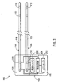
[0034]図2は、埋込型医療システム100をより詳細に示す。ここでは、刺激装置102は、刺激エンジン206、検知回路204、およびコントローラ202を備える。従来の刺激エンジン206は、ヘッダブロック108内の刺激リード104との電気接続部210を介して刺激経路に印加される、刺激パルスおよび再充電パルスを生成する。検知回路204は、ヘッダブロック108内の検知リード114との接続部208を介して、生理学的信号を取り込む。検知機能および刺激機能が1つまたは複数の同じリードを使って提供される実施形態では、刺激エンジン206と検知回路204との両方が、同じ1つまたは複数のリードに、適宜結合され得る。かかる選択肢は、図2のリード114について破線を用いて図示され、刺激エンジン206の任意選択の電気的接続部は、リード114に電気的に接続されており、電極118または120の一方が刺激するために使用されているのに対して、他方の電極は検知するために使用されていることを示す。
[0034] Figure 2 shows the implantable
[0035]刺激エンジン206は、様々な形態の療法の間に、電圧制御された刺激または電流制御された刺激を提供することができる。刺激エンジン206が実施する、患者の運動障害にうまく対処するための深部脳刺激(DBS:deep brain stimulation)療法に有効であると考えられている、電気刺激のパラメータおよび対応する範囲の具体例は、以下を含む。
[0035] The
1.周波数:刺激信号は、たとえば、約0Hzから約10,000Hzの間、ある例では約0Hzから約500Hzの間、または約2Hzから約250Hzの間の、第1の周波数範囲内の信号成分を含むことができる。 1. Frequency: The stimulation signal includes signal components within a first frequency range, for example, between about 0 Hz and about 10,000 Hz, in some examples between about 0 Hz and about 500 Hz, or between about 2 Hz and about 250 Hz. be able to.
2.電圧振幅:約0ボルトから約25ボルトの間など、約0ボルトから約50ボルトの間。
3.電流振幅:電流振幅は、約0ミリアンペアから約40ミリアンペアの間、または約0から25ミリアンペアの間であり得る。
2. Voltage swing: between about 0 volts and about 50 volts, such as between about 0 volts and about 25 volts.
3. Current Amplitude: Current amplitude can be between about 0 and about 40 milliamps, or between about 0 and 25 milliamps.
4.パルス幅:約10マイクロ秒から約1000マイクロ秒の間、または約10マイクロ秒から約450マイクロ秒の間など、約1マイクロ秒から約5000マイクロ秒の間。
[0036]検知回路204は、刺激信号を回避することで、刺激部位の近位で生理学的信号を取り込むことができる。たとえば、検知回路204は、刺激信号の間ばかりでなく、もしあれば、刺激信号の後の能動的再充電部分の間で、ブランキングを利用することができる。従って、刺激パルスおよび能動的再充電パルスは、検知回路204が、刺激パルス間の時間の中で、正確な生理学的データを取り込むことができるように、検知回路204に悪影響を与えない。
4. Pulse width: between about 1 microsecond and about 5000 microseconds, such as between about 10 microseconds and about 1000 microseconds, or between about 10 microseconds and about 450 microseconds.
[0036]
[0037]この例では、コントローラ202は、検知回路204および刺激エンジン206の動作を調整する。コントローラ202は、刺激療法中に生じる刺激の様々な動作段階を、起動および停止する。段階は、刺激パルスが送達される刺激出力段階と、刺激エンジン206内の刺激経路の中の結合コンデンサ上の電圧をクリアする再充電段階とを含み得る。段階はまた、再充電なしの期間を含み得る。同様に、受動的再充電信号が単独で使用される場合、コントローラ202は、検知回路204のブランキングスイッチを起動して、刺激信号、および受動的再充電信号のピークなどの受動的再充電信号の少なくとも一部を除去する。能動的再充電パルス、その後に続く短い受動的再充電信号、およびその後に続く長い再充電のない期間では、生理学的信号を検知するための所望の時間に応じて、能動的再充電パルスの一部または全部を除去することに加えて、一部の受動的再充電信号が除去され得る。
[0037] In this example, the
[0038]コントローラ202は、様々な形態であり得る。たとえば、コントローラ202は、刺激エンジン206および検知回路204の動作をもたらすプログラミング命令を実施する、汎用のプログラム可能なプロセッサを含み得る。他の例として、コントローラ202は、専用プロセッサおよび/またはハードウェアで実現されたデジタル論理回路を含み得る。
[0038] The
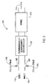
[0039]図3は、刺激パルスばかりでなく、もしあれば能動的再充電パルスの一部または全部を除去する、検知回路204の一例を示す。各検知電極118、120は、コントローラ202によって制御されるブランキングスイッチ302、304に電気的に結合されている。ブランキングスイッチは、個別のトランジスタなどのシリコンで、または以下で論じられる、より複雑な構成で実現され得る。コントローラ202は、スイッチに、電極118、120からの信号を導通させるか、または信号の導通を停止させる、ブランキング制御信号306、308を提供する。スイッチ302、304は、再充電段階後の時間から、次の刺激段階の開始前の時間まで導通し、検知信号からの刺激アーチファクトを除去するために、少なくとも刺激段階およびその後に続く再充電段階のピークの間に導通を停止する。
[0039] Figure 3 shows an example of a
[0040]ブランキングスイッチ302、304の後に、それぞれの信号経路内で、検知された信号から無関係の周波数をなくする高域通過フィルタおよび低域通過フィルタの両方を含むフィルタ310が続くことができる。フィルタ処理された信号は、検知された信号出力314を生成するために、所望される通りに振幅を拡大する、従来の差動増幅器312への入力として提供される。フィルタ310は、ブランキング期間中に生じ得る、DCから減結合するための高域通過フィルタを含み得る。フィルタ310は、波形の広がりを回避し、高周波の干渉による整流効果を回避するための、低域通過フィルタを含むことができる。
[0040] The blanking switches 302, 304 may be followed in their respective signal paths by
[0041]図4は、刺激療法の波形400およびブランキング制御信号420を含む、1組の信号およびその関連するタイミングを示す。図に見られるように、刺激療法の波形400は、パルス幅PWSを持つ刺激パルス402、その後に続く比較的短いオフ期間404(たとえば64~96μs)、その後に続く反対の極性の能動的再充電パルス406を含む。能動的再充電を使用することによって、再充電パルス406は、受動的再充電パルスのように減衰するのではなく、安定した振幅で提供され得る。能動的再充電パルス406はまた、受動的再充電パルスのピークよりも大きい振幅を持つことができ、従って、コンデンサをクリアするために再充電を行う時間は、劇的に低減される。さらに、生理学的信号を検知する前にコンデンサをクリアすることは、非神経信号からアーチファクトを取り除くのに有益である。従って、この例にあるように、能動的再充電パルス406は、刺激パルス402の終了直後に提供される。
[0041] FIG. 4 shows a set of signals and their associated timing, including a
[0042]ブランキング制御信号420は、ブランキング制御スイッチを導通状態にバイアスして電流が流れることを可能にする振幅で保持される。しかし、ブランキング制御信号420は、ブランキング制御スイッチを導通状態から非導通状態にバイアス解除して電流が流れないようにする反転パルス422を含む。ブランキング制御信号420は、ブランキング制御信号反転パルス422が刺激パルス402の直前に始まり再充電パルス406の直後に終わるように、刺激波形400に適時に同期される。その結果、ブランキング制御信号反転パルス422により、刺激パルス402全体および能動的再充電パルス406の少なくとも大部分の間、電流の流れが遮断される。
[0042] The blanking
[0043]能動的再充電パルス406は、刺激パルス402のパルス幅に対して一定し得るパルス幅PWARを持つ。この場合、能動的再充電パルス406の振幅は、パルス幅の時間内にコンデンサを効果的にクリアするよう設定され得る。上記のように、コンデンサをクリアすることは、信号アーチファクトを取り除く助けとなる。これを確実に実現する1つのやり方は、能動的再充電の振幅を刺激パルスの振幅のある比率に設定し、検知された信号を測定し、比率を調整し、そして信号アーチファクトが最小になるまで繰り返すことである。これは、図9を参照して以下により詳細に論じられる。
[0043] The
[0044]一旦能動的再充電パルス406が完了し、再充電のない非常に短い期間408(たとえば8~12μs)408が生じた後に、刺激エンジンの受動的再充電スイッチが導電状態に遷移する間、受動的再充電期間410が生じる。受動的再充電410は、次の刺激パルスのためにコンデンサを完全に準備するコンデンサの平衡化を完了し、それによって刺激の振幅のロスを避け、あらゆる電荷中性の問題を回避する。受動的再充電410の持続時間TPRは、特定の固定値(たとえば、264~396μs)に設定され、次いで効果的にコンデンサをクリアして信号アーチファクトを最小限に抑えるように、受動的再充電の固定された持続時間に照らして、能動的再充電の比率が調整されることを可能にし得る。
[0044] Once the
[0045]次いで、比較的長い再充電のない期間412が、受動的再充電期間410の後に続く。再充電のない期間412は、受動的再充電412の終了と次の刺激パルスの開始との間の有効な時間に等しい持続時間TNRを持つ。この次の刺激パルスは、刺激エンジンによって現在使用されている刺激の、所与の比率に従って発生する。
[0045] A relatively long no-
[0046]能動的再充電パルス406の終わり、および再充電のない期間412の始めの近くのある点で、ブランキングスイッチは、信号部分424で、ブランキング信号420の状態の反転で示されるように、反転される。信号部分424の間、ブランキングスイッチは、受信された信号を導通して、検知された信号の取り込みおよび増幅を可能にする。従って、検知された信号は、少なくとも再充電のない期間412の間に、取り込まれ増幅されている。ある実施形態では、検知された信号はまた、受動的再充電410の一部または全部の間、および可能性として、能動的再充電パルス406の終了部分またはオフ期間408の間に取り込まれてもよい。
[0046] At some point near the end of the
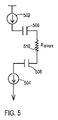
[0047]図5~図8は、刺激エンジンが、図4の刺激波形400の位相のそれぞれをもたらすために利用することができる、回路構成の例を示す。図5は、刺激パルス402を生成するための構成を具体的に示す。この例の刺激エンジンは、刺激経路の第1のコンデンサ506を通って、刺激電極が配置されている身体の組織(たとえば、脳によってもたらされる抵抗、RBRAIN)を通って、かつ刺激経路の別のコンデンサ508を通って電流を流す、第1の電流源502を備える。第2の電流源504は、この電流をシステムのアースに引き込む。複数の電流源502、504が示されているが、その代わりに、単一の電流源が使用され得ることが理解されよう。さらに、電流源が図5に示されているが、その代わりに、1つまたは複数の電圧源が使用され得ることがさらに理解されよう。
[0047] FIGS. 5-8 illustrate example circuitry that the stimulation engine may utilize to provide each of the phases of the
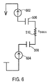
[0048]図6は、能動的再充電パルス406を生成するための構成を具体的に示す。この例の刺激エンジンは、図5の電流源502、504とは反対方向に、刺激経路の第2のコンデンサ508を通って、身体の組織(たとえば、RBRAIN)を通って、かつ刺激経路の第1のコンデンサ506を通って電流を流す、第1の電流源602を備える。第2の電流源604は、この電流をシステムのアースに引き込む。複数の電流源602、604が示されているが、その代わりに、単一の電流源が使用され得ることが理解されよう。さらに、電流源が図6に示されているが、その代わりに、1つまたは複数の電圧源が使用され得ることがさらに理解されよう。
[0048] FIG. 6 illustrates a configuration for generating an
[0049]図7は、受動的再充電期間410をもたらすための構成を具体的に示す。ここでは、刺激エンジンは、両方の刺激経路を接地し、それによって両方のコンデンサ506、508を、低インピーダンス経路を介してアースに短絡させる。図10に関して以下で論じられるように、この低インピーダンス経路は、心臓システムのECG信号などの非神経学的な発生源からのアーチファクトが取り込まれ増幅されることを可能にし得る。従って、受動的再充電の段階は、たとえば、図4に関して上記で論じられたように、264~396μsなどの最小の一定時間に、最短に留められる。
[0049] FIG. 7 illustrates a configuration for providing a
[0050]図8は、再充電のない期間412をもたらすための構成を具体的に示す。ここでは、刺激エンジンは、いかなる特定の電圧電位にも電気的に接続しないことによって、両方の刺激経路が電気的に浮くことを可能にする。システムのアースへのこの高インピーダンス経路は、検知回路の差動増幅器における非神経学的信号の同相除去をもたらす。
[0050] FIG. 8 illustrates a configuration for providing a
[0051]図9は、上記で論じられた能動的再充電比率を設定するためにコントローラ202によって使用され得る、1組の論理演算を示す。この例の能動的再充電比率は、能動的再充電パルス406の振幅を基準の能動的再充電パルスの振幅の何パーセントかになるよう設定し、検知された信号内のアーチファクトを最小にするという観点から、刺激経路のコンデンサ506、508を最良にクリアするため、この基準は、典型的には、刺激パルス402の振幅である。最初は、動作902で、刺激波形400が、それぞれの反復が異なる能動的再充電比率を使用して、繰り返し利用される。たとえば、最初の反復で比率0.8を使用し、2度目に0.9を使用し、3度目に1を使用し、4度目に1.1を使用し、5度目に1.2を使用することができる。
[0051] Figure 9 illustrates a set of logical operations that may be used by the
[0052]1組の能動的再充電比率がそれぞれ使用されると、動作904で、結果として生じる各検知された信号のピーク間の振幅が測定される。次いで、コントローラ202は、動作906において、検知された信号の最小ピーク間振幅を生成した能動的再充電比率を選択する。次いで、刺激エンジンは、動作908において、能動的再充電パルス406の振幅を設定するために選択された能動的再充電比率を使用した、刺激波形400の生成を開始する。次いで、埋込型医療装置102が、コントローラ202に、何らかのやり方で刺激波形400を変更させるプログラムを受信するなどまで、刺激エンジンはいつまでも続行し、次いで埋込型医療装置は、プログラムが、能動的再充電比率はいくらあるべきかを既に特定していない限り、コントローラ202に、図9の動作を再度使用した能動的再充電比率の設定のトリガを与え得る。
[0052] Once each set of active recharge ratios is used, in
[0053]別の例が、動作910に至る図9の破線の動作フローによって示され、生理学的な変数および装置の変数が経時的にドリフトするかもしれず、その結果、異なる能動的再充電比率が最終的にはより良い選択となり得る可能性を説明している。この例では、コントローラ202は、能動的再充電比率が最初に選択された時から24時間など、設定された時間に達するまで、刺激波形400が、選択された能動的再充電比率で継続することを可能にし得る。その時点で、コントローラ202は、ピーク間振幅を最小にする能動的再充電比率を再度見つけるために図9の動作900を繰り返し、次いで動作910で、その能動的再充電を、測定された時間の次の期間で使用するよう選択することができる。
[0053] Another example is illustrated by the dashed operational flow of FIG. It explains the possibility that it could ultimately be the better choice. In this example, the
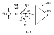
[0054]図10は、受動的再充電構成をモデル化する等価回路1000を示す。この回路は、心臓1002などの非神経学的な発生源、ならびに身体を介した、検知回路の差動増幅器1020のノード1016、1018(たとえば、検知電極118、120)までの電気経路、および刺激経路のノード1014(たとえば刺激ノード110)までの電気経路を備える。抵抗1004、1006、1008、および1010は、様々なノード間に位置する組織を表す。この抵抗は、通常1.5キロオームの範囲にある。この受動的再充電構成では、刺激経路ノード1014は、図7のようにアースに接続されている。従って、電流が心臓1004から組織の抵抗1004を通って検知ノード1016に流れる、確立された電気経路がある。
[0054] Figure 10 shows an
[0055]ノード1016の増幅器入力がアースに短絡していないことを考えると、電気経路は、組織の抵抗1006を通って中央ノード1012まで続き、中央ノード1012は、ノード1018での増幅器1020の大きな入力インピーダンスのために、組織の抵抗1010を通る電流がほとんどまたは全くないので、本質的に検知ノード1018と同じ電圧を持つ。電気経路は、中央ノード1012からさらなる組織の抵抗1008を通ってシステムアースである刺激ノード1014まで続く。従って、心臓1002によって生成されたこの電流の流れは、ノード1016に第1の電圧が生じ、一方、ノード1018に第2の電圧が生じるという結果をもたらす。ノード1016の電圧(VE2)、および式2で示されるノード1018の電圧(VE0)は、心臓1002の電圧(VHeart)、組織1016、1018の抵抗(Rtissue)、および装置漏れ抵抗1004(Rleakage)の関数である。ノード1016の電圧(VE2)およびノード1018の電圧(VE0)は、それぞれ式1および式2で、以下に示される。
[0055] Given that the amplifier input at
(式1)VE2=VHeart×(2×Rtissue)/(Rleakage+(2×Rtissue))
(式2)VE0=VHeart×(Rtissue)/(Rleakage+(2×Rtissue))
[0056]式1および式2から分かるように、ノード1018の電圧は、ノード1016の電圧の半分である。差動増幅器1020がノード1016における信号と1018における信号との間の差を増幅することを考えると、かなりの量の心臓信号が増幅されている。以下でより詳細に論じられる図12A、図12B、および図12Cは、能動的再充電はあるが再充電のない期間がない組合せ、最後に能動的再充電、非常に短い受動的再充電期間、次いで長い再充電のない期間の組合せでの、この構成のみを使用した結果を示す。
(Formula 1) VE2=VHeart×(2×Rtissue)/(Rleakage+(2×Rtissue))
(Formula 2) VE0=VHeart×(Rtissue)/(Rleakage+(2×Rtissue))
[0056] As can be seen from Equations 1 and 2, the voltage at
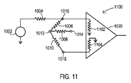
[0057]図11は、再充電のない期間の構成をモデル化した等価回路1100を示す。この回路は、心臓1002などの非神経学的な発生源、ならびに身体を介した、検知ノード1016、1018および刺激ノード1014までの電気経路を備える。しかし、この再充電のない構成では、刺激経路ノード1014は、図8のように電気的に浮いていることが可能である。従って、電流が心臓1004から組織の抵抗1008を通って流れることができる、確立された低インピーダンス電気経路はもはや存在しない。
[0057] FIG. 11 shows an
[0058]差動増幅器1020は、抵抗1102および1104として表される、それぞれの差動入力における入力インピーダンスを持つ。これらは通常、2メガオームなどのメガオーム範囲である。これらの入力インピーダンスは図10の受動的再充電構成1000にも存在するが、ノード1014からアースへの低インピーダンス経路が、入力インピーダンスを、ノード1016および1018における電圧と無関係にする。しかし、図11の再充電のない構成1100では、ノード1014が浮くことを可能にすることは、電流が、差動増幅器1020の入力に流れ込むだけになるという結果をもたらす。従って、これらの入力インピーダンスは重要である。
[0059]これらの入力インピーダンスが信号経路内の組織によって示される組織の抵抗、具体的にはノード1016と1018との間の抵抗1006および1010よりも劇的に大きいことを考えると、ノード1016に存在する電圧は、ノード1018に存在する電圧と本質的に同じである。ノード1016の電圧は、本質的に、心臓1002の電圧(VHeart)、漏れ抵抗1004(Rleakage)、および増幅器入力インピーダンス1102(Rinput)の関数である。ノード1018の電圧は、本質的に心臓1002の電圧(VHeart)、漏れ抵抗1004(Rleakage)、増幅器入力インピーダンス1104(Rinput)、および組織の抵抗1006、1010(2×Rtissue)の関数である。従って、ノード1016の電圧(VE2)およびノード1018の電圧(VE0)は、それぞれ式3および式4で、以下の通りである。
[0059] Given that these input impedances are dramatically greater than the tissue resistance presented by the tissue in the signal path, specifically
(式3)VE2=VHeart×(Rinput)/(Rleakage+Rinput)
(式4)VE0=VHeart×(Rtissue)/(Rleakage+(2×Rtissue)+Rinput)
[0060]検知電極間の差は些細であり、その差は、分母に2つの組織の抵抗を加えた結果にすぎないことが分かる。約3キロオームの足し算である分母へのこの足し算は、約2メガオームの入力抵抗を含む、より大きな分子と比較して、重要ではない。この些細な差だけが存在することを考えると、心臓の信号は、主に2つの検知電極間の同相信号として提示され、従って増幅器1020による心臓信号の同相除去が行われる。
(Formula 3) VE2=VHeart×(Rinput)/(Rleakage+Rinput)
(Formula 4) VE0=VHeart×(Rtissue)/(Rleakage+(2×Rtissue)+Rinput)
[0060] It can be seen that the difference between the sensing electrodes is insignificant and is simply the result of adding the resistance of the two tissues to the denominator. This addition to the denominator, which is about 3K ohms addition, is insignificant compared to the larger numerator, which contains an input resistance of about 2 megohms. Given that only this small difference exists, the cardiac signal is presented primarily as an in-phase signal between the two sensing electrodes, thus common-mode rejection of the cardiac signal by
[0061]図10および図11の構成では、取り込まれるべき生理学的信号、すなわち標的部位から発せられる神経学的信号は、一方の検知ノード1016から他方の検知ノード1018への大きな差を提供することになる。取り込まれるべきこの生理学的信号は、一方の検知電極の近くの領域から他方の検知電極に向かって伝播し、その結果2つの検知電極間に差動信号をもたらす。この差動信号は、差動増幅器1020によって増幅され、最終的に検知された信号としてコントローラ202に提供され、そこで信号は、以降の目的のために使用されるか、または後で引き出すために格納され得る。
[0061] In the configurations of Figures 10 and 11, the physiological signal to be captured, ie, the neurological signal emanating from the target site, provides a large difference from one
[0062]図12A~図12Cは、差動増幅器1020によって増幅された、検知された信号のスペクトル画像を示す。周波数は縦軸に沿って表され、時間は横軸に沿って表される。図示されるように、トレースは、最大強度の周波数を示している。図12Aは、受動的再充電のみを使用した結果を実証するスペクトル画像1202を示す。図12Bは、短い能動的再充電を、次の刺激パルスの時間まで延びる長い受動的再充電と共に使用した結果を実証するスペクトル画像1206を示す。これらのスペクトル画像1202および1206の両方に見られるように、垂直スパイクによって示される、広い周波数(たとえば、最大100Hz)にわたる、かなりの心臓エネルギーがある。心臓エネルギーの存在を表すスパイクは、楕円1204および1208によって示される領域内で明らかである。こうした強度の心臓エネルギーは、図10に示す状態によって増幅された信号内に現れる。
[0062] FIGS. 12A-12C show spectral images of the detected signal amplified by the
[0063]受動的再充電がほんの短い時間、たとえば330μsである図4の刺激波形400による、図12Cのスペクトル画像1210へ移ると、受動的再充電は非常に短時間であるため、心臓のエネルギーはほとんどまたは全く取り込まれていない。従って、図11の再充電のない回路構成1100では、検知期間を管理し、同相除去は対応する長い再充電のない期間に行われているので、心臓エネルギーは、検知された信号から取り除かれる。楕円1212によって示される領域内のトレースには、もはや垂直スパイクがないので、心臓エネルギーがないことは明らかである。
[0063] Moving to the
[0064]能動的再充電を利用してコンデンサをより迅速にクリアすることは、図12Cに示される長い再充電のない期間を可能にする。しかし、能動的再充電は、埋込型医療装置102によってエネルギーが提供されることを必要とする。上記で論じられ、図6に示されるように、電流源602および604は、刺激経路のキャパシタ506、508を通る電流を逆方向に流して、刺激パルスの間に蓄積された電荷をより迅速にクリアする。従って、能動的再充電は、受動的再充電のみが使用されている場合よりも急速に、埋込型医療装置の電池内の電荷量を減少させる可能性がある。
[0064] Using active recharge to clear the capacitor more quickly allows for the long recharge-free periods shown in FIG. 12C. Active recharging, however, requires energy to be provided by the implantable
[0065]バッテリのこの増加した消耗を考慮するため、埋込型医療装置102のある実施形態では、能動的再充電が必要かどうかを判断するために、図13の例1300のような論理演算を利用することができる。装置の状態、患者の生理機能などの経時的な変化のために、心臓エネルギーが検知された信号内にアーチファクトとして取り込まれる可能性が変動するかもしれない。従って、能動的再充電は、例1300に従って、好ましからざるアーチファクトを取り除くのに必要な時にだけ利用され得る。
[0065] To account for this increased depletion of the battery, some embodiments of the implantable
[0066]こうした論理演算は、動作1302で、長い受動的再充電を含む刺激波形を使用しながら、コントローラ202が検知信号を取得することで始まる。この時点で、この波形は、能動的再充電がまだ必要とされていない場合などで受動的再充電のみが使用されていてもよく、または能動的再充電と受動的再充電の両方を既に含んでいてもよい。しかし、この検出プロセスの実施について、受動的再充電の期間は意味を持っているべきであり、それにより、受動的再充電期間中の検知のためのウィンドウが、非神経学的発生源の有意な複数のサイクルを可能にする。たとえば、受動的再充電は、受動的再充電のその期間中に少なくとも10回の心拍が発生したことを確実にするために、15秒間活動状態であり得る。
[0066] Such logic operations begin at
[0067]検知された信号が取得されると、コントローラ202は、動作1304において、検知閾値を使って検知信号を生成する。図14は、検知された信号1402および検出閾値1406の一例を示す。検出閾値は、検知された信号1402内に存在する非神経学的アーチファクトのピーク1408より低いが、検知信号1402内の神経学的信号のピークより高い、ある振幅に設定される。検出閾値を使用することで検出信号1404を生成し、検出信号は、検知された信号1402が検出閾値1406を超えるそれぞれの時点でのパルス1410を含む。
[0067] Once the sensed signal is obtained, the
[0068]検出信号1404を取得すると、コントローラ202は、動作1306において、設定された数のパルス、たとえば10個のパルスについての、検出信号パルス間の平均間隔(図14のTAVE)を計算する。次いで、この平均間隔は、関心のある非神経学的信号にとって典型的な期間を定義する範囲と比較され得る。たとえば、典型的な脈拍数は、0.375秒間隔(すなわち脈拍160/分)から1.5秒間隔(すなわち脈拍40/分)までのいずれかである。質問動作1308でコントローラ202によって判断されるように、平均間隔が、検出信号が関心のある非神経学的発生源によって生成されていない可能性が高いことを示す範囲外にある場合、動作1312で、コントローラ202は、受動的再充電だけが使われるモードを利用する。平均間隔がこの範囲内に入る場合、コントローラ202は、動作1310で、能動的再充電、その後に続く短い受動的再充電期間、およびその後に続く長い再充電のない期間を含むモードを利用する。
[0068] Upon obtaining the
[0069]例1300の一実施形態では、論理演算は終了し、装置は選択されたモードをいつまでも使用し続ける。たとえば、外部のプログラマがコントローラ202に動作1300を繰り返すよう命令するまで、モードは継続され得る。別の実施形態では、動作フローの破線で示されるように、動作1310または1312でモードが選択された後、コントローラ202は、動作1314で、24時間などの設定された期間にわたって、選択されたモードを使って継続する。次いで、コントローラ202は、その時に最も適切なモードを再度設定するために、動作1302から始まる動作を繰り返す。従って、埋込型医療装置102は、動作1314において設定された期間だけは、理想的ではないかもしれないモードで動作する。
[0069] In one embodiment of example 1300, the logic operation ends and the device continues to use the selected mode indefinitely. For example, the mode may continue until an external programmer instructs
[0070]実施形態が具体的に示され説明されてきたが、本発明の趣旨および範囲から逸脱することなく、その中で形態および詳細における他の様々な変更がなされ得ることが、当業者によって理解されよう。 [0070] Although embodiments have been particularly shown and described, it will be appreciated by those skilled in the art that various other changes in form and detail may be made therein without departing from the spirit and scope of the invention. be understood.
Claims (18)
前記刺激出力に波形を提供する刺激エンジンであって、前記波形は、刺激パルス、その後に続く能動的(active)再充電パルス、その後に続く受動的(passive)再充電、その後に
続く再充電のない期間を含む刺激エンジンと、
第1の検知入力と、
前記第1の検知入力に接続される差動増幅器と、
前記再充電のない期間の少なくとも一部の間に、前記差動増幅器から生理学的信号を取得するコントローラであって、前記刺激エンジンに前記波形を繰り返し生成させるコントローラと、
を備える、埋込型医療装置。 a stimulation output;
A stimulation engine for providing a waveform to the stimulation output, the waveform comprising a stimulation pulse followed by an active recharge pulse followed by a passive recharge followed by a recharge. a stimulus engine that includes no period;
a first sensing input;
a differential amplifier connected to the first sense input;
a controller that acquires a physiological signal from the differential amplifier during at least a portion of the non-recharging period and causes the stimulation engine to repeatedly generate the waveform;
An implantable medical device comprising:
1組の能動的再充電比率がそれぞれ使用されると、前記コントローラは、結果として生じる各検知された信号のピーク間の振幅を測定し(904)、
次に、前記コントローラは、検知された信号の最小ピーク間振幅を生成した能動的再充電比率を選択し(906)、
次に、前記刺激エンジンは、能動的再充電パルスの振幅を設定するために選択された能動的再充電比率を使用した、刺激波形の生成を開始し(908)、
次に、埋込型医療装置が、コントローラに所定のやり方で前記刺激波形を変更させるプログラムを受信するまで、前記刺激エンジンはいつまでも続行する、
請求項1から7までのいずれか一項に記載の埋込型医療装置。
the controller repeatedly utilizes waveforms of the stimulus output using different active recharge ratios (902);
When each set of active recharge ratios is used, the controller measures (904) the resulting peak-to-peak amplitude of each sensed signal;
Next, the controller selects (906) the active recharge ratio that produced the minimum peak-to-peak amplitude of the sensed signal;
Next, the stimulation engine begins generating a stimulation waveform using the selected active recharge ratio to set the amplitude of the active recharge pulse (908);
The stimulation engine then continues indefinitely until the implantable medical device receives a program that causes the controller to modify the stimulation waveform in a predetermined manner.
8. An implantable medical device according to any one of claims 1-7.
前記第1の電極と電気的に結合された刺激出力と、
前記刺激出力に波形を提供する刺激エンジンであって、前記波形は、刺激パルス、その後に続く能動的再充電パルス、その後に続く受動的再充電、その後に続く再充電のない期間を含む刺激エンジンと、
前記第2の電極と電気的に結合された第1の検知入力と、
作動増幅を提供するために前記第1の検知入力に接続された差動増幅器と、
前記再充電のない期間の少なくとも一部の間に、前記差動増幅器から生理学的信号を取得するコントローラであって、刺激エンジンに前記波形を繰り返し生成させるコントローラと
を具備する埋込型医療装置と
を備える埋込型医療システム。 at least one implantable medical lead comprising a first electrode and a second electrode;
a stimulation output electrically coupled to the first electrode;
A stimulation engine for providing a waveform to the stimulation output, the waveform comprising a stimulation pulse followed by an active recharge pulse followed by a passive recharge followed by a period of no recharge. When,
a first sensing input electrically coupled to the second electrode;
a differential amplifier connected to the first sense input to provide differential amplification;
a controller that acquires a physiological signal from the differential amplifier during at least a portion of the non-recharging period, the controller causing a stimulation engine to repeatedly generate the waveform; and an implantable medical system comprising:
1組の能動的再充電比率がそれぞれ使用されると、前記コントローラは、結果として生じる各検知された信号のピーク間の振幅を測定し(904)、
次に、前記コントローラは、検知された信号の最小ピーク間振幅を生成した能動的再充電比率を選択し(906)、
次に、前記刺激エンジンは、能動的再充電パルスの振幅を設定するために選択された能動的再充電比率を使用した、刺激波形の生成を開始し(908)、
次に、埋込型医療装置が、コントローラに所定のやり方で前記刺激波形を変更させるプログラムを受信するまで、前記刺激エンジンはいつまでも続行する、
請求項11から15までのいずれか一項に記載の埋込型医療装置。 the controller repeatedly utilizes waveforms of the stimulus output using different active recharge ratios (902);
When each set of active recharge ratios is used, the controller measures (904) the resulting peak-to-peak amplitude of each sensed signal;
Next, the controller selects (906) the active recharge ratio that produced the minimum peak-to-peak amplitude of the sensed signal;
Next, the stimulation engine begins generating a stimulation waveform using the selected active recharge ratio to set the amplitude of the active recharge pulse (908);
The stimulation engine then continues indefinitely until the implantable medical device receives a program that causes the controller to modify the stimulation waveform in a predetermined manner.
16. An implantable medical device according to any one of claims 11-15.
Applications Claiming Priority (3)
| Application Number | Priority Date | Filing Date | Title |
|---|---|---|---|
| US15/444,997 | 2017-02-28 | ||
| US15/444,997 US10471259B2 (en) | 2017-02-28 | 2017-02-28 | Devices and methods for sensing physiological signals during stimulation therapy |
| PCT/US2018/012758 WO2018160271A1 (en) | 2017-02-28 | 2018-01-08 | Devices and methods for sensing physiological signals during stimulation therapy |
Publications (2)
| Publication Number | Publication Date |
|---|---|
| JP2020508739A JP2020508739A (en) | 2020-03-26 |
| JP7127047B2 true JP7127047B2 (en) | 2022-08-29 |
Family
ID=61054551
Family Applications (1)
| Application Number | Title | Priority Date | Filing Date |
|---|---|---|---|
| JP2019544646A Active JP7127047B2 (en) | 2017-02-28 | 2018-01-08 | Apparatus and method for sensing physiological signals during stimulation therapy |
Country Status (5)
| Country | Link |
|---|---|
| US (3) | US10471259B2 (en) |
| EP (1) | EP3589357B1 (en) |
| JP (1) | JP7127047B2 (en) |
| CN (1) | CN110337313B (en) |
| WO (1) | WO2018160271A1 (en) |
Families Citing this family (14)
| Publication number | Priority date | Publication date | Assignee | Title |
|---|---|---|---|---|
| US10596379B2 (en) | 2015-02-16 | 2020-03-24 | Newronika S.r.l. | Apparatus and method for treating neurological disorders |
| US10471259B2 (en) | 2017-02-28 | 2019-11-12 | Medtronic, Inc. | Devices and methods for sensing physiological signals during stimulation therapy |
| IT201800002962A1 (en) | 2018-02-22 | 2019-08-22 | Newronika Srl | APPARATUS FOR THE TREATMENT OF NEUROLOGICAL DISORDERS USING ELECTROSTIMULATION AND METHOD OF PROCESSING THE NEUROLOGICAL SIGNAL COLLECTED BY THIS APP |
| US11318309B2 (en) | 2018-12-13 | 2022-05-03 | Newronika S.P.A. | Method and apparatus for treating Tourette Syndrome by brain stimulation |
| EP3946561B1 (en) | 2019-04-04 | 2024-08-21 | Boston Scientific Neuromodulation Corporation | System for selecting neuromodulation parameters using electrospinogram |
| US11344728B2 (en) | 2019-05-28 | 2022-05-31 | Aleva Neurotherapeutics | Neurostimulation device with recording patch |
| CN114555178B (en) * | 2019-08-06 | 2025-05-16 | 波士顿科学神经调制公司 | Neural sensing in implantable stimulator devices during passive charge recovery |
| US12599329B2 (en) * | 2020-06-19 | 2026-04-14 | Inspire Medical Systems, Inc. | Sense amplifier for a physiological sensor and/or other sensors |
| CN116157178A (en) | 2020-07-17 | 2023-05-23 | 纽罗尼卡公司 | Systems and methods for adaptive deep brain stimulation |
| US12558530B2 (en) | 2022-02-21 | 2026-02-24 | Medtronic, Inc. | Sensing evoked compound action potential (ECAP) |
| US12208269B2 (en) * | 2022-03-14 | 2025-01-28 | Medtronic, Inc. | Calibration for ECAP sensing |
| US20240108878A1 (en) * | 2022-09-30 | 2024-04-04 | Medtronic, Inc. | Controlling electrode potentials |
| WO2024204823A1 (en) * | 2023-03-30 | 2024-10-03 | 大学共同利用機関法人自然科学研究機構 | Deep brain stimulation device |
| CN118750773B (en) * | 2024-09-03 | 2025-02-11 | 杭州神络医疗科技有限公司 | Nerve stimulator, control method and system |
Citations (4)
| Publication number | Priority date | Publication date | Assignee | Title |
|---|---|---|---|---|
| US20030204223A1 (en) | 2002-04-26 | 2003-10-30 | Medtronic, Inc. | Independent therapy programs in an implantable medical device |
| US20060224199A1 (en) | 2005-03-31 | 2006-10-05 | Zeijlemaker Volkert A | System for waveform stimulation compensating electrode polarization |
| US20140163638A1 (en) | 2012-12-07 | 2014-06-12 | Boston Scientific Neuromodulation Corporation | Patient Posture Determination and Stimulation Program Adjustment in an Implantable Stimulator Device Using Impedance Fingerprinting |
| JP2014522261A (en) | 2011-05-13 | 2014-09-04 | サルーダ・メディカル・ピーティーワイ・リミテッド | Method and apparatus for measurement of neural response |
Family Cites Families (12)
| Publication number | Priority date | Publication date | Assignee | Title |
|---|---|---|---|---|
| US7493174B2 (en) * | 2004-09-23 | 2009-02-17 | Medtronic, Inc. | Implantable medical lead |
| US7822483B2 (en) | 2006-02-24 | 2010-10-26 | Medtronic, Inc. | Electrical and activation field models for configuring stimulation therapy |
| US7751888B1 (en) * | 2006-08-28 | 2010-07-06 | Pacesetter, Inc. | Systems and methods for delivering stimulation pulses using an implantable cardiac stimulation device |
| US20100114209A1 (en) * | 2008-10-31 | 2010-05-06 | Medtronic, Inc. | Communication between implantable medical devices |
| US8447404B2 (en) * | 2010-03-05 | 2013-05-21 | Endostim, Inc. | Device and implantation system for electrical stimulation of biological systems |
| WO2014146016A2 (en) * | 2013-03-15 | 2014-09-18 | Alfred E. Mann Foundation For Scientific Research | Current sensing multiple output current stimulators with fast turn on time |
| US9238141B2 (en) | 2013-08-15 | 2016-01-19 | Medtronic, Inc. | Devices and methods to provide stimulation therapy in the presence of external conditions that induce undesirable perturbations |
| US9504837B2 (en) * | 2013-10-25 | 2016-11-29 | Medtronic, Inc. | Automated phrenic nerve stimulation and pacing capture threshold test |
| US9717428B2 (en) * | 2014-02-07 | 2017-08-01 | Medtronic, Inc. | Devices and methods for sensing physiological signals during stimulation therapy |
| EP2926863B1 (en) * | 2014-04-01 | 2019-07-31 | Sorin CRM SAS | Use of an implantable cardiac generator for myocardial stimulation, defibrillation and/or resynchronisation as a vagus nerve stimulation (VNS) generator |
| US10625087B2 (en) * | 2014-04-24 | 2020-04-21 | Medtronic, Inc. | Therapy delivery methods and circuits for an implantable medical device |
| US10471259B2 (en) | 2017-02-28 | 2019-11-12 | Medtronic, Inc. | Devices and methods for sensing physiological signals during stimulation therapy |
-
2017
- 2017-02-28 US US15/444,997 patent/US10471259B2/en active Active
-
2018
- 2018-01-08 EP EP18701867.6A patent/EP3589357B1/en active Active
- 2018-01-08 JP JP2019544646A patent/JP7127047B2/en active Active
- 2018-01-08 WO PCT/US2018/012758 patent/WO2018160271A1/en not_active Ceased
- 2018-01-08 CN CN201880014255.XA patent/CN110337313B/en active Active
-
2019
- 2019-10-02 US US16/590,661 patent/US11160983B2/en active Active
-
2021
- 2021-10-14 US US17/501,732 patent/US12303692B2/en active Active
Patent Citations (6)
| Publication number | Priority date | Publication date | Assignee | Title |
|---|---|---|---|---|
| US20030204223A1 (en) | 2002-04-26 | 2003-10-30 | Medtronic, Inc. | Independent therapy programs in an implantable medical device |
| US20060224199A1 (en) | 2005-03-31 | 2006-10-05 | Zeijlemaker Volkert A | System for waveform stimulation compensating electrode polarization |
| JP2014522261A (en) | 2011-05-13 | 2014-09-04 | サルーダ・メディカル・ピーティーワイ・リミテッド | Method and apparatus for measurement of neural response |
| US20150164354A1 (en) | 2011-05-13 | 2015-06-18 | John Louis Parker | Method and apparatus for measurement of neural response |
| US20140163638A1 (en) | 2012-12-07 | 2014-06-12 | Boston Scientific Neuromodulation Corporation | Patient Posture Determination and Stimulation Program Adjustment in an Implantable Stimulator Device Using Impedance Fingerprinting |
| JP2016503333A (en) | 2012-12-07 | 2016-02-04 | ボストン サイエンティフィック ニューロモデュレイション コーポレイション | Patient posture determination using impedance fingerprinting and stimulation program adjustment in an implantable stimulator device |
Also Published As
| Publication number | Publication date |
|---|---|
| US10471259B2 (en) | 2019-11-12 |
| US20200030610A1 (en) | 2020-01-30 |
| WO2018160271A1 (en) | 2018-09-07 |
| US20180243564A1 (en) | 2018-08-30 |
| CN110337313B (en) | 2023-08-29 |
| US20220032065A1 (en) | 2022-02-03 |
| JP2020508739A (en) | 2020-03-26 |
| EP3589357B1 (en) | 2022-03-23 |
| EP3589357A1 (en) | 2020-01-08 |
| US11160983B2 (en) | 2021-11-02 |
| US12303692B2 (en) | 2025-05-20 |
| CN110337313A (en) | 2019-10-15 |
Similar Documents
| Publication | Publication Date | Title |
|---|---|---|
| JP7127047B2 (en) | Apparatus and method for sensing physiological signals during stimulation therapy | |
| US11793438B2 (en) | Neural sensing in an implantable stimulator device during the provision of active stimulation | |
| CN114555178B (en) | Neural sensing in implantable stimulator devices during passive charge recovery | |
| US20230218217A1 (en) | Circuitry to Assist with Neural Sensing in an Implantable Stimulator Device in the Presence of Stimulation Artifacts | |
| US9717428B2 (en) | Devices and methods for sensing physiological signals during stimulation therapy | |
| US20210361213A1 (en) | Devices and methods for sensing physiological signals during stimulation therapy | |
| US9895542B2 (en) | Device and method for selective nerve stimulation | |
| US20120277813A1 (en) | Pacing and Stimulation Apparatus and Methods | |
| US9421385B2 (en) | Therapy delivery architecture for implantable medical device | |
| US20170259069A1 (en) | System and method for generating premodulated interferential currents, particularly for spinal cord stimulation | |
| EP4647023A2 (en) | Controlled switching network for electrophysiology procedures | |
| WO2026073317A1 (en) | Methods and systems for mitigating unintended stimulus by neuromodulation devices | |
| WO2025039032A1 (en) | Improved measurement of evoked responses to neural stimulation |
Legal Events
| Date | Code | Title | Description |
|---|---|---|---|
| A621 | Written request for application examination |
Free format text: JAPANESE INTERMEDIATE CODE: A621 Effective date: 20200716 |
|
| A131 | Notification of reasons for refusal |
Free format text: JAPANESE INTERMEDIATE CODE: A131 Effective date: 20210615 |
|
| A977 | Report on retrieval |
Free format text: JAPANESE INTERMEDIATE CODE: A971007 Effective date: 20210618 |
|
| A521 | Request for written amendment filed |
Free format text: JAPANESE INTERMEDIATE CODE: A523 Effective date: 20210906 |
|
| A131 | Notification of reasons for refusal |
Free format text: JAPANESE INTERMEDIATE CODE: A131 Effective date: 20220124 |
|
| A521 | Request for written amendment filed |
Free format text: JAPANESE INTERMEDIATE CODE: A523 Effective date: 20220415 |
|
| TRDD | Decision of grant or rejection written | ||
| A01 | Written decision to grant a patent or to grant a registration (utility model) |
Free format text: JAPANESE INTERMEDIATE CODE: A01 Effective date: 20220728 |
|
| A61 | First payment of annual fees (during grant procedure) |
Free format text: JAPANESE INTERMEDIATE CODE: A61 Effective date: 20220817 |
|
| R150 | Certificate of patent or registration of utility model |
Ref document number: 7127047 Country of ref document: JP Free format text: JAPANESE INTERMEDIATE CODE: R150 |