JP7128043B2 - Foil transfer device and foil transfer method - Google Patents
Foil transfer device and foil transfer method Download PDFInfo
- Publication number
- JP7128043B2 JP7128043B2 JP2018125999A JP2018125999A JP7128043B2 JP 7128043 B2 JP7128043 B2 JP 7128043B2 JP 2018125999 A JP2018125999 A JP 2018125999A JP 2018125999 A JP2018125999 A JP 2018125999A JP 7128043 B2 JP7128043 B2 JP 7128043B2
- Authority
- JP
- Japan
- Prior art keywords
- transfer
- foil
- workpiece
- angle
- region
- Prior art date
- Legal status (The legal status is an assumption and is not a legal conclusion. Google has not performed a legal analysis and makes no representation as to the accuracy of the status listed.)
- Active
Links
Images


Classifications
-
- B—PERFORMING OPERATIONS; TRANSPORTING
- B41—PRINTING; LINING MACHINES; TYPEWRITERS; STAMPS
- B41F—PRINTING MACHINES OR PRESSES
- B41F16/00—Transfer printing apparatus
- B41F16/0006—Transfer printing apparatus for printing from an inked or preprinted foil or band
- B41F16/0093—Attachments or auxiliary devices
-
- B—PERFORMING OPERATIONS; TRANSPORTING
- B44—DECORATIVE ARTS
- B44C—PRODUCING DECORATIVE EFFECTS; MOSAICS; TARSIA WORK; PAPERHANGING
- B44C1/00—Processes, not specifically provided for elsewhere, for producing decorative surface effects
- B44C1/16—Processes, not specifically provided for elsewhere, for producing decorative surface effects for applying transfer pictures or the like
- B44C1/165—Processes, not specifically provided for elsewhere, for producing decorative surface effects for applying transfer pictures or the like for decalcomanias; sheet material therefor
- B44C1/17—Dry transfer
- B44C1/1712—Decalcomanias applied under heat and pressure, e.g. provided with a heat activable adhesive
Landscapes
- Engineering & Computer Science (AREA)
- Mechanical Engineering (AREA)
- Holo Graphy (AREA)
- Decoration By Transfer Pictures (AREA)
- Labeling Devices (AREA)
- Laser Beam Processing (AREA)
Description
本発明は箔転写装置及び箔転写方法に関する。 The present invention relates to a foil transfer device and a foil transfer method.
構造色を持つことにより、観察角度によってその色彩や模様を変更する箔フィルムと、そのような箔フィルムを被加工材の表面に転写する転写装置または転写方法が、従来技術として知られている(特許文献1)。 A foil film that changes its color and pattern depending on the viewing angle by having a structural color, and a transfer device or transfer method for transferring such a foil film to the surface of a workpiece are known as prior art ( Patent document 1).
上記のような箔フィルムは、表面に配列された構造により、反射光が回折や干渉、散乱等の現象を起こす。そのため、箔フィルムに対して相対的に観察角度を変えた場合に、または観察者に対して箔フィルムの角度を変えた場合に、箔フィルムの色彩や模様が変わるように視認される。 The foil film as described above causes phenomena such as diffraction, interference, and scattering of reflected light due to the structure arranged on the surface. Therefore, when the viewing angle relative to the foil film is changed, or when the angle of the foil film with respect to the observer is changed, the colors and patterns of the foil film are perceived to change.
このような箔フィルムの配置の方法の一つとして、被加工材上で複数の領域を定め、各領域で箔フィルムの角度が異なるように配置する方法が考えられる。このような配置方法を採用した場合、同一の角度から観察しても、領域ごとに箔フィルムの色彩や模様が異なって視認されるため、多様な表現が可能となる。 As one of the methods of arranging such foil films, a method of defining a plurality of regions on the workpiece and arranging the foil films at different angles in each region is conceivable. When such an arrangement method is employed, even when viewed from the same angle, the colors and patterns of the foil film are visually recognized differently in each region, making it possible to create a variety of expressions.
しかし、上記のような配置を採用した場合、領域ごとに、互いに角度の異なる箔フィルムをあらかじめ複数種用意して箔フィルムを転写する必要があり、転写にかかるコストが増大するおそれがあった。 However, when the above arrangement is adopted, it is necessary to prepare in advance a plurality of types of foil films having different angles for each region and transfer the foil films, which may increase the transfer cost.
上記課題に鑑み、本発明の目的は、転写コストを抑制可能な箔フィルムの転写装置及び転写方法を提供することにある。 SUMMARY OF THE INVENTION In view of the above problems, it is an object of the present invention to provide a foil film transfer apparatus and transfer method capable of suppressing transfer costs.
上記課題を解決するため、本発明は、箔フィルムを被加工材に対して転写可能な転写部と、制御部と、を備え、前記制御部は、前記転写部を用いて、前記被加工材に対して第1角度に配置された1つの箔フィルムを、前記被加工材の第1領域に転写する第1転写処理と、前記被加工材に対して前記第1角度とは異なる第2角度に配置された前記1つの箔フィルムを、前記転写部を用いて前記被加工材の前記第1領域とは異なる第2領域に転写する第2転写処理と、を実行可能である箔転写装置を提供する。 In order to solve the above problems, the present invention includes a transfer unit capable of transferring a foil film to a workpiece, and a control unit, wherein the control unit uses the transfer unit to transfer the workpiece to the workpiece. a first transfer process to transfer a foil film positioned at a first angle to the workpiece onto a first region of the work piece; and a second angle to the work piece different from the first angle. and a second transfer process of transferring the one foil film placed in the work piece to a second region different from the first region of the workpiece using the transfer unit. offer.
また、本発明は、箔フィルムを被加工材に対して転写する転写方法であって、前記被加工材に対して第1角度に配置された1つの箔フィルムを、前記被加工材の第1領域に転写する第1転写処理と、前記被加工材に対する前記1つの箔フィルムの配置を前記第1角度とは異なる第2角度へ変更する変更処理と、前記被加工材に対して第2角度に配置された前記1つの箔フィルムを、前記被加工材の前記第1領域とは異なる第2領域に転写する第2転写処理と、を含む転写方法を提供する。 The present invention also provides a transfer method for transferring a foil film to a work material, wherein one foil film arranged at a first angle with respect to the work material is transferred to the work material at a first angle. a first transfer process of transferring to a region; a change process of changing the placement of the one foil film with respect to the work piece to a second angle different from the first angle; and a second angle with respect to the work piece. a second transfer process of transferring the one foil film placed on the workpiece to a second region different from the first region of the workpiece.
また、本発明は、箔フィルムを被加工材に対して転写可能な転写部と、制御部と、を備え、前記制御部は、前記転写部を用いて、前記被加工材に対して第1角度に配置された1つの箔フィルムを、前記被加工材の第1領域に転写する第1転写処理と、前記被加工材に対して前記第1角度とは異なる第2角度に配置された前記1つの箔フィルムを、前記被加工材の前記第1領域と少なくとも一部が重複する第2領域に、前記転写部を用いて転写する第2転写処理と、を実行可能である箔転写装置を提供する。 Further, the present invention includes a transfer unit capable of transferring a foil film onto a workpiece, and a control unit, wherein the control unit uses the transfer unit to transfer the first transfer onto the workpiece. a first transfer process of transferring a foil film positioned at an angle to a first region of the work piece; a second transfer process of transferring one foil film to a second region of the material to be processed, which at least partially overlaps with the first region, using the transfer unit; offer.
本発明によれば、転写コストを抑制可能な箔フィルムの転写装置及び転写方法を提供できる。 According to the present invention, it is possible to provide a foil film transfer apparatus and a transfer method capable of suppressing transfer costs.
<実施形態>
図1~図7を参照して、本発明の実施形態に係る箔転写装置1について説明を行う。本実施形態に係る箔転写装置1は、ホログラム箔Fを重ねた被加工材Cに対してレーザー光を走査させ、被加工材Cに対してホログラム箔Fを所定形状に転写する。図1から図4に示すように、箔転写装置1は、筐体10、制御部20、転写部30、上下方向駆動機構40、前後方向駆動機構50、左右方向駆動機構60、変更部70、設置部80、及び光吸収部90を含む。箔転写装置1は、外部のコンピュータ2と通信可能に接続されている。箔転写装置1自体がコンピュータ2の機能を有していてもよい。ホログラム箔Fは、本発明における箔フィルムの一例である。
<Embodiment>
A
コンピュータ2は、被加工材Cに転写する所定の図柄(文字の輪郭等)の形状に沿った走査経路のデータを作成して箔転写装置1に送信する。コンピュータ2は、たとえば一般的なパーソナルコンピュータを使用することができる。走査経路の作成処理は、コンピュータ2に予めインストールされた、所定のプログラムを用いて実行する。
The computer 2 creates data of a scanning path along the shape of a predetermined pattern (outline of characters, etc.) to be transferred to the workpiece C, and transmits the data to the
[筐体]
図1及び図2に示すように、筐体10はベース部12を備える。ベース部12には、制御部20と電気的に接続する電源スイッチ11が設けられる。また、ベース部12の上面には、設置部80が固定される。
[Chassis]
As shown in FIGS. 1 and 2, the
なお、本実施形態においては、図1に示すように、前後左右及び上下の方向を定める。詳細には、筐体10に対して電源スイッチ11の備わる方向を前方とし、その反対の方向を後方とする。また、筐体10を前面から見た場合を基準として、左右の方向を定める。筐体10において、ベース部12が配置される側を下方とし、その反対を上方とする。
In this embodiment, as shown in FIG. 1, the front, rear, left, right, and upper and lower directions are determined. Specifically, the direction in which the
[制御部]
箔転写装置1の全体の動作は、制御部20によって制御されている。図4に示すように、制御部20は、転写部30、上下方向駆動機構40、前後方向駆動機構50、及び左右方向駆動機構60と通信可能に接続され、それらを制御する。制御部20の構成は特に限定されないが、本実施形態においては、プログラムを記憶するROMと、プログラムを実行するCPUと、CPUによる処理において作業領域を提供するRAMと、不揮発性メモリであって各種データを記憶するNVRAMとを主に備える。
[Control part]
The overall operation of the
[転写部]
図1から図4に示すように、筐体10には、転写部30が設けられる。転写部30は、レーザー発振器31、照射部32、光ファイバ33、及びキャリッジ34を備える。
[transcription part]
As shown in FIGS. 1 to 4, the
レーザー発振器31は、半導体レーザー発振器である(図3)。レーザー発振器31に所定の電流を流すことにより、レーザー発振器31からレーザー光が発振される。レーザー発振器31の性能は、たとえば、波長450nm、最大出力1Wである。なお、レーザー発振器31は、半導体レーザーに限らず、固体レーザーや気体レーザーであってもよい。
The
図3に示すように、照射部32は、レーザー発振器31と光ファイバ33を介して接続される。照射部32は、レンズ32aと、下部においてレンズ32aを支持し、上下に延びる略円筒形部材32bとを備える。
As shown in FIG. 3 , the
レンズ32aは、本実施形態では球状に形成され、レーザー光が透過する材料で形成されている。なお、レンズ32aは、球状に限定されず、レンズ状や半球状であっても良い。レーザー発振器31から発振されたレーザー光は、光ファイバ33を介して照射部32に伝達され、レンズ32aを介して外部に照射される。ホログラム箔Fの転写は、レンズ32aを、光吸収部90を介してホログラム箔F及び被加工材Cに押し付け、レーザー光を照射することにより行われる。
The
図1に示すように、キャリッジ34は、照射部32をキャリッジ34の前部において支持する。キャリッジ34は、左右方向駆動機構60、前後方向駆動機構50、及び上下方向駆動機構40によって駆動可能に支持される。これらの駆動機構によって、キャリッジ34及びこれに支持される照射部32は、被加工材Cに対して、三次元方向に相対移動可能である。
As shown in FIG. 1, the
[駆動機構]
図1及び図2に示すように、上下方向駆動機構40は、上下方向駆動シャフト41と、駆動用モータ42と、昇降ベース43とを備えている。上下方向駆動シャフト41は、上下方向に延び、螺旋状にねじが切られている。上下方向駆動シャフト41の上部は筐体10に回転可能に支持され、下端部は、ベース部12に回転可能に支持されている。駆動用モータ42は、筐体10の上部に固定されるとともに、制御部20と電気的に接続されている。また駆動用モータ42の出力軸は上下方向駆動シャフト41と機械的に接続しており、上下方向駆動シャフト41を回転駆動させることが可能である。
[Drive Mechanism]
As shown in FIGS. 1 and 2 , the
昇降ベース43は、水平方向に延出する部材であり、図示せぬ上下に延びるスライドシャフトによって摺動可能に支持される。また、昇降ベース43は、上下方向駆動シャフト41と螺合している。上下方向駆動シャフト41が回転することにより、昇降ベース43は、上下方向に移動する。昇降ベース43は、前後方向に延びるスライドシャフト43a、43bを備える。
The elevating
前後方向駆動機構50は、前後方向駆動シャフト51と、駆動用モータ52と、スライドベース54とを備える。前後方向駆動シャフト51は、前後方向に延びるように昇降ベース43に設けられ、螺旋状にネジが切られている。駆動用モータ52は、昇降ベース43の後部に固定され、制御部20に電気的に接続されている。駆動用モータ52の出力軸は、前後方向駆動シャフト51の後端部と接続されており、前後方向駆動シャフト51を回転駆動させることが可能である。
The
スライドベース54は、前後方向駆動シャフト51と螺合する。また、スライドベース54は、スライドシャフト43a、43bによって摺動可能に支持されている。スライドベース54は、駆動用モータ52が駆動されると、前後方向駆動シャフト51の回転により前後方向に移動する。スライドベース54は、左右方向に延びるスライドシャフト53a、53bを備える。
The
左右方向駆動機構60は、スライドベース54と連結される。左右方向駆動機構60は、左右方向駆動シャフト61と、駆動用モータ62とを備えている。左右方向駆動シャフト61は、左右方向に延び、螺旋状にねじが切られている。駆動用モータ62の出力軸は、左右方向駆動シャフト61の右端部と機械的に接続し、左右方向駆動シャフト61を回転駆動することが可能である。駆動用モータ62は、制御部20と電気的に接続されている。
The
左右方向駆動シャフト61は、キャリッジ34と螺合する。また、スライドシャフト53a、53bは、キャリッジ34を摺動可能に支持している。駆動用モータ62が駆動されると、左右方向駆動シャフト61が回転し、キャリッジ34は、スライドシャフト53a、53bに沿って左右方向に駆動される。
The
[変更部]
図4に示すように、変更部70は、被加工材C上に載置されたホログラム箔Fの配置角度を変更する機能を備える部材である。変更部70は制御用のモータを備え、モータの出力軸がホログラム箔Fの移動または角度変更の動力源として利用される。変更部70は、制御部20と電気的に接続し、制御部20によって、その動作を制御される。
[change part]
As shown in FIG. 4, the changing
[設置部]
図1及び図2に示すように、設置部80は、ベース部12上に固定される平板状の台座81と、台座81上に着脱可能に固定される固定具82と、支持体83a、83bとを備える。本実施形態による固定具82は、左右の1対の部材を備え、被加工材Cを狭持することが可能である。固定具82は、被加工材Cを左右から狭持することにより、被加工材Cをベース部12上に固定する機能を備える。
[Installation part]
As shown in FIGS. 1 and 2, the
支持体83a、83bは、下端部が台座81に固定され、上方向に延出する略円柱状の部材である。支持体83aの上部は、光吸収部90を回動可能に支持する。
The
[光吸収部]
光吸収部90は、枠体91とフィルム92とを備える。枠体91は、上面視で矩形の枠状部材であり、フィルム92を支持する。フィルム92は、レーザー光などの光線を吸収する機能を備える。
[Light absorbing part]
The
図5に示すように、光吸収部90は支持体83aによって回動可能に支持され、準備位置(図5(a))と設置位置(図5(b))との間を略水平に回動可能である。光吸収部90が設置位置に配置されると枠体91が支持体83bと係合し、このため光吸収部90は、設置位置に固定される。
As shown in FIG. 5, the
[ホログラム箔及び被加工材]
ホログラム箔Fは、表面に配列された構造により、反射光が回折や干渉、散乱等の現象を起こす。そのため、一般にホログラム箔Fは、表面の構造に起因した異方性を持っている。すなわち、ホログラム箔Fに対して相対的に観察方向または観察角度を変えた場合に、若しくは、観察者に対してホログラム箔Fの方向または角度を変えた場合に、ホログラム箔Fの色彩や模様が変わるように視認される。
[Hologram foil and work material]
The hologram foil F causes phenomena such as diffraction, interference, and scattering of reflected light due to the structure arranged on the surface. Therefore, the hologram foil F generally has anisotropy due to its surface structure. That is, when the observation direction or observation angle is changed relative to the hologram foil F, or when the direction or angle of the hologram foil F is changed with respect to the observer, the colors and patterns of the hologram foil F change. seen to change.
被加工材Cは、略直方体形状の筐体を有する部材である。被加工材Cの筐体は樹脂製であり、具体的にはアクリルや、ABS、ポリプロピレン、ポリスチレン、ポリカーボネートなどによって形成される。 The workpiece C is a member having a substantially rectangular parallelepiped housing. The housing of the material to be processed C is made of resin, specifically acrylic, ABS, polypropylene, polystyrene, polycarbonate, or the like.
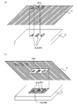
[転写処理]
箔転写装置1を用いてホログラム箔Fを被加工材Cに転写する際の、処理内容について以下に詳述する。なお、理解を容易にするため、転写処理の具体例として、図7に示すホログラム箔Fを、図柄G1a及び図柄G2aに従って、被加工材C上で隣接する第1領域R1及び第2領域R2に順次転写する処理を説明する。この転写処理では、図柄G1b及び図柄G2bが、それぞれ被加工材C上の第1領域R1及び第2領域R2に、最終的に形成される(図7(b))。
[Transfer processing]
Details of processing when the hologram foil F is transferred to the workpiece C using the
転写処理において、最初にユーザは、光吸収部90を、準備位置(図5(a))に配置する。次にユーザは、被加工材Cを、固定具82に狭持させることにより、ベース部12に対して相対移動不能となるように固定する。ユーザは、被加工材Cの固定後、被加工材Cの上にホログラム箔Fを覆うように載置する。さらにユーザは、光吸収部90を準備位置から設置位置に回動させ(図5(b))、被加工材C及びホログラム箔Fの設置を完了する。被加工材C及びホログラム箔Fの設置が完了すると、ユーザは、コンピュータ2を用いて、転写すべき所定の図柄G1a、G2a、及び、角度変更処理(後述)において用いられる所定角度を入力し、制御部20に対して処理の開始を指示する。
In the transfer process, the user first places the
ユーザからの指示を受け、制御部20は、図6に示される処理を実行する。なお、制御部20の操作は、筐体10上に操作部を配置し、これを用いて行う構成としてもよい。
Upon receiving an instruction from the user, the
制御部20の実行する処理を、図6を用いて以下に説明する。ステップS1において、制御部20は、第1転写処理を開始する。第1転写処理は、図柄G1aを、被加工材Cの第1領域R1に転写する処理である。第1転写処理において、制御部20は、上下方向駆動機構40、前後方向駆動機構50、及び左右方向駆動機構60を制御し、図柄G1aの形状に従って照射部32を走査する。
Processing executed by the
同時に制御部20は、レーザー発振器31を起動して、レーザー光を照射部32のレンズ32aから照射する。このとき、レンズ32aはフィルム92に接触するとともに、図示せぬバネによって、フィルム92、ホログラム箔F及び被加工材Cに向けて付勢されている。レーザー光は、フィルム92を介してホログラム箔Fへ照射される。ホログラム箔Fのレーザー光の照射を受けた部分が加熱され、被加工材Cの第1領域R1へ転写される。
At the same time, the
ステップS3において、制御部20は、転写すべき図柄G1aが全て転写されたかどうかを確認する。図柄G1aの転写が完了していない場合は(S3:No)、処理をステップS1に戻し、第1転写処理を継続する。
In step S3, the
図柄G1aの転写が全て完了したと判断したとき(S3:Yes)、制御部20はレーザー発振器31を停止してレーザー光の照射を停止する(S5)。このようにして、制御部20は、第1転写処理を終了させる。
When it is determined that the transfer of all the patterns G1a is completed (S3: Yes), the
制御部20は、ステップS7において角度変更処理を行う。制御部20は、変更部70を制御し、ホログラム箔Fを略水平方向に回動させ、被加工材Cに対する相対角度の変更を行う。あるいは、制御部20は、変更部70を制御し、ホログラム箔Fを回転しながら前後、左右に移動させる。上記の処理を行うことにより、ホログラム箔Fの被加工材Cに対する相対角度を変更する。
The
制御部20は、ステップS9において、ホログラム箔Fの回動角が所定角度に達したかどうか判断する。制御部20は、ホログラム箔Fの回動角が所定角度に達していないと判断した場合(S9:No)、処理をステップS7に戻し、ホログラム箔Fの角度変更処理を継続する。
In step S9, the
所定角度に達したと判断した場合(S9:Yes)、制御部20は、変更部70の制御を停止し(S11)、第2転写処理を行う(S13)。角度変更処理の結果、ホログラム箔Fの被加工材Cに対する角度は、図7(a)に示される第1角度から、図7(b)に示される第2角度に変更される。
When it is determined that the predetermined angle has been reached (S9: Yes), the
第2転写処理は、図柄G2aを被加工材Cの第2領域R2へ転写する処理である。制御部20は、第2転写処理において、レーザー発振器31を起動して、レーザー光を照射部32から照射する。同時に、制御部20は、照射部32を走査することによって、図柄G2aの第2領域R2への転写処理を行う。
The second transfer process is a process of transferring the pattern G2a to the second region R2 of the workpiece C. As shown in FIG. In the second transfer process, the
ステップS15において、制御部20は、図柄G2aの転写処理が完了したかどうかを確認する。図柄G2aの転写処理が完了していないと判断した場合(S15:No)、制御部20は、処理をステップS13に戻して転写処理を継続する。
In step S15, the
図柄G2aの転写処理が全て完了したと判断した場合、制御部20はレーザー発振器31を停止してレーザー光の照射を停止する(S17)。このようにして、制御部20は、第2転写処理を終了させる。
When determining that the transfer processing of the pattern G2a is completed, the
<変形例>
なお、本実施形態では、転写を行うための光発生器として、レーザー発振器31を用いる構成について述べたが、本発明はこのような構成に限られない。たとえば、レーザー発振器31に代わり、発光ダイオードを用いることも可能である。また、発光ダイオードに限らず、流す電流を変えることで光の出力を変えることができるような素子等を使用することもできる。また、転写部30にホットスタンプ方式や、ヒートペン方式に対応した機構を用いることも可能である。また、光吸収部90を用いずに転写処理を行うことも可能である。
<Modification>
In this embodiment, the configuration using the
本実施形態では、変更部70によってホログラム箔Fの角度変更処理が行われたが、本発明はこのような構成に限定されない。第1転写処理完了後に、ユーザの手によって、角度変更処理が行われても良い。この場合は、ユーザが光吸収部90を回動して光吸収部90を準備位置に配置し(図5(a))、ホログラム箔Fを水平方向に移動することにより被加工材Cに対する角度を変更する。その後、光吸収部90を設置位置(図5(b))に戻し、第2転写処理を開始する。
In this embodiment, the changing
また、本実施形態では、照射部32のみが移動する例について述べたが、本発明はこのような構成に限定されない。すなわち、固定された照射部32に対し、設置部80が前後方向、左右方向、及び上下方向に移動することで箔転写を行ってもよい。この場合、上下方向駆動機構40、前後方向駆動機構50、及び左右方向駆動機構60は、設置部80を駆動させる構成(たとえば、設置部80を三軸方向に移動させるための駆動用モータ)を有する。或いは、照射部32と設置部80との双方を移動する構成としてもよい。
Moreover, although the example in which only the
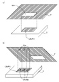
本実施形態では、第1領域R1及び第2領域R2は互いに隣接し、これに伴い、図柄G1b及び図柄G2bは、互いに隣接するように転写、形成されていた。しかし、本発明はこの実施形態に限定されるものではない。第1領域R1及び第2領域R2は、少なくとも一部が重複するように位置しても良い。 In this embodiment, the first region R1 and the second region R2 are adjacent to each other, and along with this, the pattern G1b and the pattern G2b are transferred and formed so as to be adjacent to each other. However, the invention is not limited to this embodiment. The first region R1 and the second region R2 may be positioned so as to at least partially overlap.
図8に示すように、第1の変形例として、第2領域R2が第1領域R1内に位置し、図柄G3bの上に重なるように図柄G4bが形成されても良い。この場合であっても、図柄G3bと図柄G4bとは、ホログラム箔Fの角度が互いに異なるように転写、形成されたものであるため、それぞれ異なる模様、色彩として視認される。 As shown in FIG. 8, as a first modification, the second region R2 may be positioned within the first region R1, and the pattern G4b may be formed so as to overlap the pattern G3b. Even in this case, since the pattern G3b and the pattern G4b are transferred and formed so that the angle of the hologram foil F is different from each other, they are visually recognized as different patterns and colors.
図9(a)に示すように、第2の変形例として、第1領域R1及び第2領域R2が互いに離間するように位置し、図柄G5b及び図柄G6bが形成されても良い。または図9(b)に示すように、第3の変形例として、第1領域R1及び第2領域R2が互いに一部重複するように配置され、図柄G7b及び図柄G8bが形成されても良い。これらの場合であっても、被加工材C上に形成された各図柄は、ホログラム箔Fの角度が異なるように転写、形成されたものであるため、それぞれ異なる模様、色彩として視認される。 As shown in FIG. 9A, as a second modification, the first region R1 and the second region R2 may be positioned apart from each other, and the pattern G5b and the pattern G6b may be formed. Alternatively, as shown in FIG. 9B, as a third modification, the first region R1 and the second region R2 may be arranged so as to partially overlap each other to form the pattern G7b and the pattern G8b. Even in these cases, the patterns formed on the material to be processed C are transferred and formed so that the angles of the hologram foil F are different, so they are visually recognized as different patterns and colors.
また、図9(c)に示すように、第4の変形例として、第1領域R1が第2領域R2内に位置し、図柄G9bを覆うように図柄G10bが形成されても良い。ホログラム箔Fが光を透過可能である場合、図柄G10bの下にある図柄G9bは視認可能である。この場合、図柄G9bと図柄106とは、互いにホログラム箔Fの角度が異なるように転写、形成されたものであるため、それぞれ異なる模様、色彩として視認される。 Further, as shown in FIG. 9C, as a fourth modification, the first region R1 may be positioned within the second region R2, and the pattern G10b may be formed so as to cover the pattern G9b. When the hologram foil F can transmit light, the pattern G9b below the pattern G10b is visible. In this case, since the pattern G9b and the pattern 106 are transferred and formed so that the angles of the hologram foil F are different from each other, they are visually recognized as different patterns and colors.
なお、本発明における箔フィルムは、ホログラム箔Fに限定されない。箔フィルムとして、公知のメタリック箔、ハーフミラーメタリック箔、顔料箔、多色印刷箔等を採用することも可能である。 In addition, the foil film in the present invention is not limited to the hologram foil F. As the foil film, known metallic foil, half-mirror metallic foil, pigment foil, multicolor printed foil, etc. can be employed.
なお、本発明における被加工材の素材は、樹脂に限定されず、金属や陶器など、他の材料から形成されていてもよい。また、本発明における被加工材の筐体の形状は、本実施形態のように直方体形状に限定されず、各側面が曲面で構成されていても良い。 In addition, the material of the material to be processed in the present invention is not limited to resin, and may be formed from other materials such as metal and pottery. Further, the shape of the housing of the workpiece in the present invention is not limited to the rectangular parallelepiped shape as in the present embodiment, and each side surface may be curved.
<効果>
このように、本実施形態に係る箔転写装置1は、ホログラム箔Fを被加工材Cに対して転写可能な転写部30と、制御部20とを備える。制御部20は、転写部30を用いて、被加工材Cに対して第1角度に配置された1つのホログラム箔Fを、被加工材Cの第1領域R1に転写する第1転写処理を実行可能であり、さらに、被加工材Cに対して第1角度とは異なる第2角度に配置されたホログラム箔Fを、転写部30を用いて被加工材Cの第1領域R1とは異なる第2領域R2に転写する第2転写処理を実行可能である。
<effect>
As described above, the
また、箔転写装置1は、1つのホログラム箔Fの被加工材Cに対する配置を変更可能な変更部70をさらに備えており、制御部20は、変更部70を用いて、1つのホログラム箔Fの配置を第1角度から第2角度へ変更する変更処理を実行可能である。
In addition, the
上記構成による箔転写装置1、または箔転写装置1を用いた転写方法においては、1枚のホログラム箔Fを用い、ホログラム箔Fの被加工材Cに対する角度を領域ごとに変化させて、転写処理を行う。そのため、互いに角度の異なるホログラム箔Fを複数枚用意する必要がなく、転写処理に係るコストを抑制することができる。
In the
箔転写装置1の転写部30は、レーザー光を発光する照射部32を有する。
The
従来の箔フィルムの転写方法(箔押し方法)として、接着剤を蒸着させた箔に対し金型(版)を押し当て、高温高圧下において被加工材に図柄を熱転写するホットスタンプ方式や、高温のペン状部材を用いたヒートペン方式が知られている。このような従来の箔転写方法は、高温に弱い樹脂製品への適用が難しい。 Conventional foil film transfer methods (foil stamping methods) include the hot stamping method, in which a metal mold (plate) is pressed against a foil on which an adhesive has been vapor-deposited, and the pattern is thermally transferred to the workpiece under high temperature and pressure conditions. A heat pen method using a pen-shaped member is known. Such a conventional foil transfer method is difficult to apply to resin products that are vulnerable to high temperatures.
一方、上記構成による箔転写装置1では、細いレーザー光を制御しながら照射し、箔フィルムの加熱を行う。そのため、箔転写装置1は、被加工材Cのような樹脂製品に対しても、ホログラム箔Fなどの箔フィルムの転写を可能としている。
On the other hand, in the
箔転写装置1は、レーザー光を吸収する光吸収部90を備え、制御部20は、第1転写処理及び第2転写処理において、照射部32から発光されたレーザー光を、光吸収部90を介してホログラム箔Fに照射する。
The
上記構成によれば、光吸収部90によってホログラム箔F上での光の吸収率を均質にし、ホログラム箔Fに供給される熱を転写部分において均質化できる。そのため、箔表面の光の吸収率が部位によって異なる場合であっても、転写ムラが低減、または防止される。
According to the above configuration, the
上記構成によるホログラム箔Fは、構造色を有する。上記構成によれば、転写された領域ごとにホログラム箔Fの色彩や模様が変わったように視認され、多様な表現が可能となる。 The hologram foil F having the above configuration has a structural color. According to the above configuration, the colors and patterns of the hologram foil F are visually recognized as different for each transferred area, and various expressions are possible.
また、第1の実施形態では、第1領域R1と第2領域R2とは互いに隣接している。第1領域R1と第2領域R2とが隣接している場合、転写された図柄G1bが、図柄G2bを背景として浮き出ているような視覚的効果が得られる。 Moreover, in the first embodiment, the first region R1 and the second region R2 are adjacent to each other. When the first region R1 and the second region R2 are adjacent to each other, a visual effect is obtained in which the transferred pattern G1b stands out against the background of the pattern G2b.
本実施形態に係る箔転写装置1は、ホログラム箔Fを被加工材Cに対して転写可能な転写部30と、制御部20とを備える。制御部20は、転写部30を用いて、被加工材Cに対して第1角度に配置された1つのホログラム箔Fを、被加工材Cの第1領域R1に転写する第1転写処理を実行可能であり、さらに、被加工材Cに対して第1角度とは異なる第2角度に配置されたホログラム箔Fを、転写部30を用いて被加工材Cの第1領域R1と少なくとも一部が重複する第2領域R2に転写する第2転写処理を実行可能である。
The
上記構成による箔転写装置1では、1枚のホログラム箔Fを用いて、2つの領域において転写処理を行う。そのため、ホログラム箔Fを複数枚用意する必要がなく、転写処理に係るコストを抑制することができる。
In the
上記実施形態は、発明の例として提示したものであり、発明の範囲を限定するものではない。上記の構成は、発明の要旨を逸脱しない範囲で、種々の省略、置き換え、変更を行うことができる。上記実施形態やその変形は、発明の範囲や要旨に含まれると同様に、特許請求の範囲に記載された発明とその均等の範囲に含まれる。 The above embodiments are presented as examples of the invention and do not limit the scope of the invention. Various omissions, replacements, and modifications can be made to the above configuration without departing from the scope of the invention. The above-described embodiments and modifications thereof are included in the invention described in the claims and their equivalents, as well as being included in the scope and gist of the invention.
1 箔転写装置
2 コンピュータ
10 筐体
20 制御部
30 転写部
31 レーザー発振器
32 照射部
40 上下方向駆動機構
50 前後方向駆動機構
60 左右方向駆動機構
70 変更部
80 設置部
90 光吸収部
C 被加工材
F ホログラム箔
1 Foil Transfer Device 2
Claims (8)
制御部と、を備え、
前記制御部は、
前記転写部を用いて、前記被加工材に対して第1角度に配置された1つの箔フィルムを、前記被加工材の第1領域に転写する第1転写処理と、
前記被加工材に対して前記第1角度とは異なる第2角度に配置された前記1つの箔フィルムを、前記転写部を用いて前記被加工材の前記第1領域とは異なる第2領域に転写する第2転写処理と、を実行可能である箔転写装置。 a transfer unit capable of transferring the foil film to the workpiece;
a control unit;
The control unit
a first transfer process of transferring one foil film arranged at a first angle with respect to the workpiece to a first region of the workpiece using the transfer unit;
The one foil film arranged at a second angle different from the first angle with respect to the workpiece is transferred to a second area different from the first area of the workpiece using the transfer unit. and a second transfer process of transferring.
前記制御部は、前記第1転写処理および前記第2転写処理において、前記照射部から発光されたレーザー光を、前記光吸収部を介して前記1つの箔フィルムに照射することを特徴とする、請求項2に記載の箔転写装置。 further comprising a light absorbing portion that absorbs laser light,
In the first transfer process and the second transfer process, the control unit irradiates the one foil film with laser light emitted from the irradiation unit through the light absorption unit, The foil transfer device according to claim 2 .
前記被加工材に対して第1角度に配置された1つの箔フィルムを、前記被加工材の第1領域に転写する第1転写処理と、
前記被加工材に対する前記1つの箔フィルムの配置を前記第1角度とは異なる第2角度へ変更する変更処理と、
前記被加工材に対して第2角度に配置された前記1つの箔フィルムを、前記被加工材の前記第1領域とは異なる第2領域に転写する第2転写処理と、を含む転写方法。 A transfer method for transferring a foil film to a workpiece,
a first transfer process for transferring a piece of foil film positioned at a first angle with respect to the work piece to a first region of the work piece;
a changing process of changing the placement of the one foil film with respect to the workpiece to a second angle different from the first angle;
a second transfer process of transferring the one foil film positioned at a second angle with respect to the work piece to a second region of the work piece different from the first region.
制御部と、を備え、
前記制御部は、
前記転写部を用いて、前記被加工材に対して第1角度に配置された1つの箔フィルムを、前記被加工材の第1領域に転写する第1転写処理と、
前記被加工材に対して前記第1角度とは異なる第2角度に配置された前記1つの箔フィルムを、前記被加工材の前記第1領域と少なくとも一部が重複する第2領域に、前記転写部を用いて転写する第2転写処理と、を実行可能である箔転写装置。 a transfer unit capable of transferring the foil film to the workpiece;
a control unit;
The control unit
a first transfer process of transferring one foil film arranged at a first angle with respect to the workpiece to a first region of the workpiece using the transfer unit;
the one foil film arranged at a second angle different from the first angle with respect to the work piece in a second region at least partially overlapping the first region of the work piece; and a second transfer process of transferring using a transfer unit.
Priority Applications (2)
| Application Number | Priority Date | Filing Date | Title |
|---|---|---|---|
| JP2018125999A JP7128043B2 (en) | 2018-07-02 | 2018-07-02 | Foil transfer device and foil transfer method |
| US16/452,565 US11738551B2 (en) | 2018-07-02 | 2019-06-26 | Foil transfer device and method of transferring foils |
Applications Claiming Priority (1)
| Application Number | Priority Date | Filing Date | Title |
|---|---|---|---|
| JP2018125999A JP7128043B2 (en) | 2018-07-02 | 2018-07-02 | Foil transfer device and foil transfer method |
Publications (2)
| Publication Number | Publication Date |
|---|---|
| JP2020001359A JP2020001359A (en) | 2020-01-09 |
| JP7128043B2 true JP7128043B2 (en) | 2022-08-30 |
Family
ID=69054969
Family Applications (1)
| Application Number | Title | Priority Date | Filing Date |
|---|---|---|---|
| JP2018125999A Active JP7128043B2 (en) | 2018-07-02 | 2018-07-02 | Foil transfer device and foil transfer method |
Country Status (2)
| Country | Link |
|---|---|
| US (1) | US11738551B2 (en) |
| JP (1) | JP7128043B2 (en) |
Families Citing this family (1)
| Publication number | Priority date | Publication date | Assignee | Title |
|---|---|---|---|---|
| JP2020062794A (en) * | 2018-10-17 | 2020-04-23 | Dgshape株式会社 | Foil transfer device |
Citations (4)
| Publication number | Priority date | Publication date | Assignee | Title |
|---|---|---|---|---|
| JP2001138558A (en) | 1999-08-27 | 2001-05-22 | Victor Co Of Japan Ltd | Thermal transfer printer, image receiving material |
| JP2008189356A (en) | 2007-02-05 | 2008-08-21 | Jptec Kk | Continuous method for pasting molded component |
| JP5637371B2 (en) | 2010-09-24 | 2014-12-10 | 凸版印刷株式会社 | Image display body, transfer foil, and labeled article |
| JP2017226159A (en) | 2016-06-23 | 2017-12-28 | 洋治 杉山 | Transfer processing method, transfer processing apparatus, and transfer processed product |
Family Cites Families (6)
| Publication number | Priority date | Publication date | Assignee | Title |
|---|---|---|---|---|
| GB0400681D0 (en) * | 2004-01-13 | 2004-02-18 | Rue De Int Ltd | Security device |
| EP1997631B1 (en) * | 2007-05-31 | 2012-11-14 | Komori Corporation | Foil transfer apparatus |
| DE102008055142A1 (en) * | 2008-12-23 | 2010-07-01 | Manroland Ag | Operation of a cold foil unit with a printing unit |
| JP2012256021A (en) * | 2011-05-17 | 2012-12-27 | Sony Corp | Volumetric hologram, manufacturing method thereof, and diffracted light wavelength spectrum shift method |
| EP2886360B1 (en) * | 2013-12-17 | 2016-07-20 | Braun GmbH | Method of laser induced marking of an article |
| JP6612592B2 (en) * | 2015-11-12 | 2019-11-27 | ローランドディー.ジー.株式会社 | Program for creating data used in foil transfer device, foil transfer device, and foil transfer method |
-
2018
- 2018-07-02 JP JP2018125999A patent/JP7128043B2/en active Active
-
2019
- 2019-06-26 US US16/452,565 patent/US11738551B2/en active Active
Patent Citations (4)
| Publication number | Priority date | Publication date | Assignee | Title |
|---|---|---|---|---|
| JP2001138558A (en) | 1999-08-27 | 2001-05-22 | Victor Co Of Japan Ltd | Thermal transfer printer, image receiving material |
| JP2008189356A (en) | 2007-02-05 | 2008-08-21 | Jptec Kk | Continuous method for pasting molded component |
| JP5637371B2 (en) | 2010-09-24 | 2014-12-10 | 凸版印刷株式会社 | Image display body, transfer foil, and labeled article |
| JP2017226159A (en) | 2016-06-23 | 2017-12-28 | 洋治 杉山 | Transfer processing method, transfer processing apparatus, and transfer processed product |
Also Published As
| Publication number | Publication date |
|---|---|
| US11738551B2 (en) | 2023-08-29 |
| JP2020001359A (en) | 2020-01-09 |
| US20200001594A1 (en) | 2020-01-02 |
Similar Documents
| Publication | Publication Date | Title |
|---|---|---|
| JP6343255B2 (en) | Foil stamping device | |
| KR101041137B1 (en) | Substrate cutting device and substrate cutting method using same | |
| JP2005005245A (en) | Transfer method of transfer material, shape transfer method and transfer device | |
| US11305521B2 (en) | Thermal transfer apparatus and transfer method | |
| JP6505805B1 (en) | Thermal transfer device | |
| JP2018069501A (en) | Decorating device and decorating method | |
| JP7128043B2 (en) | Foil transfer device and foil transfer method | |
| JP2018069502A (en) | Foil transfer method and light absorbing film used therefor | |
| CN1684819A (en) | Laser-supported replication methods | |
| JP5735762B2 (en) | Dyeing method | |
| KR101058920B1 (en) | Substrate Cutting Device Using Laser | |
| JP2020023057A (en) | Foil transfer apparatus | |
| JP7212512B2 (en) | Image forming apparatus and image forming method | |
| JP2020023137A (en) | Thermal transfer device | |
| US20200089118A1 (en) | Foil transfer device | |
| JP7306391B2 (en) | Drawing method, erasing method, and drawing device | |
| JP6910909B2 (en) | Thermal transfer device | |
| JP6910932B2 (en) | Thermal transfer device | |
| JP7282003B2 (en) | Foil transfer device | |
| US8304688B2 (en) | Apparatuses for fabricating micro patterns using laser diode array and methods for fabricating micro patterns | |
| US20200183298A1 (en) | Image forming apparatus and image forming method | |
| JP5928631B2 (en) | 3D modeling apparatus and 3D modeling method | |
| JP7300946B2 (en) | Foil transfer device | |
| JP2021045869A (en) | Foil transfer device | |
| JP2020062794A (en) | Foil transfer device |
Legal Events
| Date | Code | Title | Description |
|---|---|---|---|
| A621 | Written request for application examination |
Free format text: JAPANESE INTERMEDIATE CODE: A621 Effective date: 20210701 |
|
| A131 | Notification of reasons for refusal |
Free format text: JAPANESE INTERMEDIATE CODE: A131 Effective date: 20220614 |
|
| A521 | Request for written amendment filed |
Free format text: JAPANESE INTERMEDIATE CODE: A523 Effective date: 20220708 |
|
| TRDD | Decision of grant or rejection written | ||
| A01 | Written decision to grant a patent or to grant a registration (utility model) |
Free format text: JAPANESE INTERMEDIATE CODE: A01 Effective date: 20220809 |
|
| A61 | First payment of annual fees (during grant procedure) |
Free format text: JAPANESE INTERMEDIATE CODE: A61 Effective date: 20220818 |
|
| R150 | Certificate of patent or registration of utility model |
Ref document number: 7128043 Country of ref document: JP Free format text: JAPANESE INTERMEDIATE CODE: R150 |
|
| R250 | Receipt of annual fees |
Free format text: JAPANESE INTERMEDIATE CODE: R250 |