JP7191908B2 - Method and apparatus for laser-assisted separation of partial pieces from planar glass members - Google Patents
Method and apparatus for laser-assisted separation of partial pieces from planar glass members Download PDFInfo
- Publication number
- JP7191908B2 JP7191908B2 JP2020159097A JP2020159097A JP7191908B2 JP 7191908 B2 JP7191908 B2 JP 7191908B2 JP 2020159097 A JP2020159097 A JP 2020159097A JP 2020159097 A JP2020159097 A JP 2020159097A JP 7191908 B2 JP7191908 B2 JP 7191908B2
- Authority
- JP
- Japan
- Prior art keywords
- glass member
- planar glass
- planar
- partial
- glass
- Prior art date
- Legal status (The legal status is an assumption and is not a legal conclusion. Google has not performed a legal analysis and makes no representation as to the accuracy of the status listed.)
- Active
Links
Images


Classifications
-
- C—CHEMISTRY; METALLURGY
- C03—GLASS; MINERAL OR SLAG WOOL
- C03B—MANUFACTURE, SHAPING, OR SUPPLEMENTARY PROCESSES
- C03B33/00—Severing cooled glass
- C03B33/09—Severing cooled glass by thermal shock
- C03B33/091—Severing cooled glass by thermal shock using at least one focussed radiation beam, e.g. laser beam
-
- B—PERFORMING OPERATIONS; TRANSPORTING
- B23—MACHINE TOOLS; METAL-WORKING NOT OTHERWISE PROVIDED FOR
- B23K—SOLDERING OR UNSOLDERING; WELDING; CLADDING OR PLATING BY SOLDERING OR WELDING; CUTTING BY APPLYING HEAT LOCALLY, e.g. FLAME CUTTING; WORKING BY LASER BEAM
- B23K26/00—Working by laser beam, e.g. welding, cutting or boring
- B23K26/50—Working by transmitting the laser beam through or within the workpiece
- B23K26/53—Working by transmitting the laser beam through or within the workpiece for modifying or reforming the material inside the workpiece, e.g. for producing break initiation cracks
-
- C—CHEMISTRY; METALLURGY
- C03—GLASS; MINERAL OR SLAG WOOL
- C03B—MANUFACTURE, SHAPING, OR SUPPLEMENTARY PROCESSES
- C03B33/00—Severing cooled glass
- C03B33/02—Cutting or splitting sheet glass or ribbons; Apparatus or machines therefor
- C03B33/0222—Scoring using a focussed radiation beam, e.g. laser
-
- C—CHEMISTRY; METALLURGY
- C03—GLASS; MINERAL OR SLAG WOOL
- C03B—MANUFACTURE, SHAPING, OR SUPPLEMENTARY PROCESSES
- C03B33/00—Severing cooled glass
- C03B33/02—Cutting or splitting sheet glass or ribbons; Apparatus or machines therefor
- C03B33/04—Cutting or splitting in curves, especially for making spectacle lenses
-
- B—PERFORMING OPERATIONS; TRANSPORTING
- B23—MACHINE TOOLS; METAL-WORKING NOT OTHERWISE PROVIDED FOR
- B23K—SOLDERING OR UNSOLDERING; WELDING; CLADDING OR PLATING BY SOLDERING OR WELDING; CUTTING BY APPLYING HEAT LOCALLY, e.g. FLAME CUTTING; WORKING BY LASER BEAM
- B23K2103/00—Materials to be soldered, welded or cut
- B23K2103/50—Inorganic materials other than metals or composite materials
- B23K2103/54—Glass
Landscapes
- Chemical & Material Sciences (AREA)
- Engineering & Computer Science (AREA)
- Physics & Mathematics (AREA)
- Organic Chemistry (AREA)
- Materials Engineering (AREA)
- Optics & Photonics (AREA)
- Mechanical Engineering (AREA)
- Plasma & Fusion (AREA)
- Oil, Petroleum & Natural Gas (AREA)
- General Chemical & Material Sciences (AREA)
- Chemical Kinetics & Catalysis (AREA)
- Health & Medical Sciences (AREA)
- Toxicology (AREA)
- Thermal Sciences (AREA)
- Re-Forming, After-Treatment, Cutting And Transporting Of Glass Products (AREA)
- Laser Beam Processing (AREA)
Description
本発明は一般的に、面状のガラス部材からの部分片のレーザアシストによる切り離しに関する。具体的には本発明は、面状のガラス部材の内側からの部分片のレーザアシストによる切り離しに関する。 The present invention relates generally to laser-assisted detachment of pieces from planar glass members. Specifically, the present invention relates to the laser-assisted detachment of pieces from the inside of a planar glass member.
国際公開第2012/006736号(WO 2012/006736 A2)から、高エネルギーのレーザパルスを用いてガラス基材に線条の形態の不可逆的な傷を引き起こすことができ、ガラスにおけるかかる複数の傷の整列によってガラスを分割できることが公知となっている。線条は超短レーザパルスによって生じ、ガラスの内側においてカー効果に基づき、プラズマが点弧するほど1点においてエネルギー密度が高くなるまで自己集光が行われる。ガラスがプラズマ発生場所の周辺に不可逆的な傷を受けるプラズマ爆発が生じる。ここからさらなる放射が放出され、この放射は自己集光を受けて、さらなるプラズマ爆発となって終了する。この効果は、強度如何に応じて複数回繰り返される。このエネルギーはガラス全厚において減少していくので、最初のプラズマスポットが最大のエネルギーを有し、最初のプラズマスポットが生成する傷も最大となる。
米国特許出願公開第2014/027951号明細書(US 2014/027951 A1)は、レーザ放射を用いてガラス、セラミックまたはサファイア等の脆性材料を分割する方法に関するものである。当該方法を用いて500μm未満の厚さの薄い基材を分割することができる。
米国特許出願公開第2015/165560号明細書(US 2015/165560 A1)は、ガラス基材から内側片を切り出すことができるレーザ手法に関するものである。当該手法は、0.7mmの厚さの薄いガラス基材に孔を形成するために用いられる。
内側輪郭を切り出すため、追加の分割線を形成して個々の切片を割断することが提案されている。他の代替的な一実施形態は、内側輪郭を加熱によって溶解して除去するというものである。
米国特許出願公開第2015/166393号明細書(US 2015/166393 A1)もレーザアシスト手法に関するものであり、当該手法によって、ガラス部材から切片を切り出すことをアシストしようとするものである。ガラス部材は0.4mmまたは0.7mmの厚さを有する。個片化は、曲げ力を加えることによって行うことができる。他の一実施形態は、追加的なCO2レーザを使用して分割線を入れ、局所的に熱応力を生じさせて、ステップごとの切り離しを実現しようというものである。
最後に、欧州特許出願公開第2754524号明細書(EP 2 754 524 A1)は、レーザ光源を用いてガラス製の面状の基材または半導体ウェハをレーザアシストにより加工する方法に関するものである。分割線に沿って行われる材料の分割は、材料の自己応力または加えられた力のいずれかによって行われる。
From WO 2012/006736 A2, high-energy laser pulses can be used to induce irreversible flaws in the form of filaments in glass substrates, and the formation of such multiple flaws in glass. It is known to split glass by alignment. The filaments are caused by ultrashort laser pulses, which are self-focusing on the basis of the Kerr effect inside the glass until the energy density at one point is so high that the plasma is ignited. A plasma explosion occurs in which the glass is irreversibly damaged around the plasma generation site. Further radiation is emitted from here, which undergoes self-focusing and ends in a further plasma explosion. This effect repeats multiple times depending on the intensity. Since this energy decreases with the thickness of the glass, the first plasma spot has the highest energy and the first plasma spot produces the highest scratches.
US 2014/027951 A1 relates to a method for splitting brittle materials such as glass, ceramic or sapphire using laser radiation. The method can be used to divide thin substrates with a thickness of less than 500 μm.
US Patent Application Publication No. 2015/165560 (US 2015/165560 A1) relates to a laser technique that can cut an inner piece out of a glass substrate. The technique is used to form holes in a thin glass substrate with a thickness of 0.7 mm.
In order to cut out the inner contour, it has been proposed to create an additional parting line to break the individual pieces. Another alternative embodiment is to melt away the inner contour by heating.
US Patent Application Publication No. 2015/166393 (US 2015/166393 A1) also relates to laser-assisted techniques, which seek to assist in cutting sections from glass members. The glass member has a thickness of 0.4 mm or 0.7 mm. Singulation can be done by applying a bending force. Another embodiment is to introduce a parting line using an additional CO2 laser to locally induce thermal stress to achieve step-by-step decoupling.
Finally,
独国特許出願公開第102012110971号明細書(DE 10 2012 110 971 A1)に、透明な被加工物の分割前処理方法が記載されており、この方法では、超短レーザパルスによって、被加工物を通って交差する整列された線条パターンが、分割線に沿って形成される。これにより、材料にはこの分割線に沿ってパーフォレーションが形成され、これにより事前傷形成がなされる。次のステップにおいて、被加工物の分割を行う。 DE 10 2012 110 971 A1 (DE 10 2012 110 971 A1) describes a method for split pretreatment of transparent workpieces, in which ultrashort laser pulses cut the workpieces into An aligned filament pattern that crosses through is formed along the parting line. The material is thereby perforated along this dividing line, thereby pre-scoring. The next step is to divide the workpiece.
1つの被加工物から所定の部分片を完全に切り離す必要がある場合、材料は分割線によって、通常は2つの完全に互いに区切られた領域に分けられる。ここで、材料に上述のような分割線に沿って線条が形成された後に後続のステップにおいて材料に適切な応力を印加すると、材料は上述の生成された規定破損線すなわち分割線に沿って分割され、この材料から、切り離された部分片と、残留する主部とが得られる。切り離された部分片は、典型的には内側部分と称され、残留する主部は外側部分と称され得る。 When it is necessary to completely separate a given piece from one workpiece, the material is divided by a parting line, usually into two completely mutually delimited regions. Now, after the material has been filamented along the split lines as described above, if suitable stresses are applied to the material in a subsequent step, the material will sag along the defined failure or split lines generated above. From this material, which is divided, the separated part pieces and the remaining main part are obtained. The separated piece is typically referred to as the inner portion and the remaining main portion may be referred to as the outer portion.
分割線が直線である場合、レーザ加工の次の切り離しは簡単になる。それに対して切り離しが困難になるのは、分割線が曲線である場合、互いに角度を成す複数の区間を有する場合、または、閉じた線を成している場合である。後者の場合は特に、内側輪郭ないしは孔を形成しなければならない場合である。たとえばこれは、ガラスプレートに窓を切り抜かなければならないときに生じる。また、上述の後者の場合は、外側輪郭の全部が分割線によって設定されたガラス部品を製造しなければならないときにも生じる。 If the parting line is straight, then cutting out following laser processing is simplified. Separation is more difficult if the dividing line is curved, has sections that form angles with each other, or forms a closed line. The latter case is particularly the case when inner contours or holes must be formed. For example, this occurs when a window has to be cut out in a glass plate. The latter case mentioned above also occurs when a glass part has to be produced whose entire outer contour is set by a parting line.
全体的に曲線の分割線、局所的に角を有する分割線、または、それ自体で閉じられた分割線に沿ってガラスを分割することが困難であるのは、かかる分離線でガラスに十分な曲げモーメントを与えることが容易ではないからである。 The difficulty in dividing glass along a generally curvilinear dividing line, a locally angled dividing line, or a dividing line closed by itself is due to the fact that such a dividing line does not allow the glass to This is because it is not easy to apply a bending moment.
にもかかわらず面状基材から内側輪郭を切り出す一手段は、欧州特許出願公開第2781296号明細書(EP 2 781 296 A1)から導き出すことができる。ここで記載されている方法は、輪郭線に沿って亀裂線を入れた後(輪郭規定ステップ)、基材から切り離すべき部分片を基材からより容易に切り離せるように、当該基材から切り離すべき部分片を高いレーザ出力で熱により変形し、または溶融する(材料変形工程または材料アブレーション工程)。切り離しをアシストするためには、切り離すべき部分片をさらに小さい小片に切り出し加工するため、部分片にさらに他の、たとえば螺旋形またはV字形の亀裂線を入れることができる。この手法の欠点は、コストが高くて経済的有用性が低減すること、および、切り離すべき部分片の破壊であり、かかる部分片の形状は、基材の残留する主部に対して正確に嵌合する形状なので、部分片が関心対象となり得る。また、部分片の破壊については、粒子および破片が生じ、これによって洗浄コストが高くなるという欠点もある。
Nevertheless, one means of cutting out an inner contour from a planar substrate can be derived from
よって、本発明の基礎となる課題は、面状のガラス部材の切り離された部分片および残留する主部の双方がこれ以上損傷することがないように、面状のガラス部材から非直線の分割線に沿って部分片を効率的かつ清浄に、特に破片無しで切り離せるようにすることである。 Thus, the problem underlying the present invention is to provide a non-linear split from a sheet glass member in such a way that both the detached partial piece and the remaining main part of the sheet glass member are not damaged any further. To enable efficient and clean separation of partial pieces along a line, especially without splinters.
課題の一側面は、それ自体で閉じた分割線に沿って内側の部分片を上述のように切り離せるようにすることである。 One aspect of the problem is to be able to separate the inner pieces as described above along a parting line that is closed on itself.
課題の他の一側面は、ガラスの切り離された部分片および残留する主部の双方において損傷となる亀裂形成のおそれを最小限にしながら、上述のような切り離しを可能にすることである。 Another aspect of the problem is to enable such separation while minimizing the risk of damaging crack formation in both the separated piece of glass and the remaining bulk.
前記課題は、独立請求項の対象だけで既に解決される。各従属請求項に、本発明の有利な実施形態および発展形態が記載されている。 Said problem is already solved solely by the subject matter of the independent claims. The respective dependent claims describe advantageous embodiments and developments of the invention.
切り離すべき部分片と残留させるべき主部とに面状のガラス部材を分ける所定の分割線に沿って、当該ガラス部材から部分片を切り離す本発明の方法は、ガラス部材の体積に線条状の傷を分割線に沿って並べて形成し、かつ、当該傷を超短パルスレーザのレーザパルスによって形成し、ガラス部材の材料はレーザパルスに対して透過性であり、レーザパルスはガラス部材の体積においてプラズマを生成し、プラズマは上述の線条状の傷を形成し、ガラス部材上におけるレーザパルスの入射点を当該ガラス部材の表面上において分割線に沿って移動させ、当該分割線に沿って並んで配置された線条状の傷を入れた後、部分片と主部とをそれぞれ完全体として維持しながら、並んだ線条状の傷において部分片を分割線に沿って主部から引き離すように、ガラス部材の主部の領域を加熱して膨張させ、および/または、ガラス部材の部分片の領域を冷却して圧縮させることに基づいている。 The method of the present invention for separating a partial piece from a planar glass member along a predetermined dividing line that divides the planar glass member into a partial piece to be separated and a main portion to be retained is a method of the present invention in which a filamentary piece is formed in the volume of the glass member. The flaws are formed side by side along the parting line, and the flaws are formed by laser pulses of an ultrashort pulse laser, the material of the glass member is transparent to the laser pulses, and the laser pulses are applied in the volume of the glass member. A plasma is generated, the plasma forms the above-mentioned linear flaws, the point of incidence of the laser pulse on the glass member is moved along the parting line on the surface of the glass member, and aligned along the parting line. After making the filament-shaped scratches arranged in , while maintaining the partial piece and the main part as a whole, the partial pieces are separated from the main part along the parting line at the aligned filament-shaped scratches. Secondly, it is based on heating and expanding regions of the bulk of the glass member and/or cooling and compressing regions of partial pieces of the glass member.
主部の膨張および/または部分片の圧縮によって、これらの各部のサイズは互いに相対的に異なって変化することとなる。部分片を冷却する場合、たとえば、主部に対する部分片の「収縮」が生じる。かかる相対的なサイズ変化によって、部分片は主部から引き離される。 Expansion of the main section and/or compression of the partial pieces will cause the sizes of these sections to change differently relative to each other. When cooling the partial piece, for example, a "shrinkage" of the partial piece relative to the main part occurs. Such relative size change pulls the partial pieces away from the main portion.
有利には、分割線に沿って並んで配置された線条状の傷を入れた後に、分割線に沿ってガラスに局所的な引張応力を引き起こして、隣り合った線条状の傷間に亀裂形成を引き起こすように、ガラス部材上におけるレーザ放射の入射点、有利には二酸化炭素レーザの入射点を、当該ガラス部材の表面上において分割線に沿って移動させる。かかる工程は「クリービング工程」とも称される。このクリービング工程は、加熱後に局所的に冷却を行って、材料に生成された引張応力を増大させることによって、支援することもできる。 Advantageously, after the linear flaws arranged side by side along the parting line, a local tensile stress is induced in the glass along the parting line to create a tension between the adjacent linear flaws. The point of incidence of the laser radiation, preferably of the carbon dioxide laser, on the glass member is moved along the dividing line on the surface of the glass member so as to cause crack formation. Such a process is also called a "cleaving process". This cleaving process can also be assisted by local cooling after heating to increase the tensile stresses created in the material.
クリービング工程は事前分割処理に供される。ガラス部材に分割線において熱力学的な応力を生成するため、ガラス部材に分割線に沿って、有利にはCO2レーザを用いて照射がなされる。この照射により、線条の傷を繋ぐ亀裂形成を分割線に沿って生じさせることができ、これにより、分割線に沿って少なくとも局所的な分割を生じさせることができ、しかも、このことは通常、主部から部分片が引き離されることなく生じさせることができる。この観点において有利なのは、主部の領域において加熱を行う工程の前、および/または、部分片の領域において冷却を行う工程の前に、クリービング工程を行うことである。 The cleaving step is subject to a pre-splitting process. In order to generate a thermodynamic stress in the glass element at the dividing line, the glass element is irradiated along the dividing line, preferably with a CO 2 laser. This irradiation can cause crack formation along the parting line that bridges the filament flaws, which can cause at least local splitting along the parting line, and this is usually , can be generated without the partial piece being pulled away from the main part. It is advantageous in this respect to carry out a cleaving step before the step of heating in the region of the main part and/or before the step of cooling in the region of the partial pieces.
線条パターン自体、および、クリービング工程によって材料に引き起こされる追加の亀裂は双方とも、材料の、分割線に沿って延在する事前傷となる。 Both the filament pattern itself and the additional cracks induced in the material by the cleaving process result in pre-fractures in the material that extend along the parting line.
本発明は、主部および部分片をそれぞれ完全体として維持するものである。主部および部分片をそれぞれ完全体として維持することの利点は、両部分とも引き続き使用できることである。どのような目的で当該分割方法を使用するかに応じて、主部または部分片のいずれか一方または双方の部分が関心対象となり得る。特に主部が関心対象である場合には、生じる残留部分および破片が少なくなり、部分片を溶解する必要なく出発材料として再使用することができるので、部分片の維持が有利である。両部分が関心対象である場合には、両部分の形状が正確に相補的となることに利点が奏され得る。さらに、切り離すべき部分を複数のより小さい小片に分割する手法と比較して、プロセスコストも格段に削減される。 The present invention keeps the main part and the partial pieces each as an integral unit. An advantage of keeping the main part and the partial pieces each as an integral part is that both parts can continue to be used. Depending on what purpose the segmentation method is used, either the main part or the partial pieces or both parts may be of interest. Partial piece maintenance is advantageous, especially if the main part is of interest, as less residual parts and debris are produced and the partial piece can be reused as starting material without the need to dissolve it. If both parts are of interest, it may be advantageous that the shapes of both parts are exactly complementary. In addition, process costs are significantly reduced compared to splitting the portion to be cut into multiple smaller pieces.
本発明に使用される、材料に規定された傷を極小空間に超短パルスレーザのレーザパルスによって形成する精密分割手法は、レーザ光との相互作用ゾーンにおいて、互いに密に位置するサブミクロン中空チャネルの形成、すなわち1μm未満の径の中空チャネルの形成によって、材料の局所的破壊が生じることに基づいている。 The precise division method used in the present invention, in which a flaw defined in a material is formed in a very small space by a laser pulse of an ultrashort pulse laser, consists of submicron hollow channels that are densely positioned in the interaction zone with the laser light. , i.e. the formation of hollow channels with a diameter of less than 1 μm, causes local disruption of the material.
レーザパルスによって形成される線条状の傷は有利には、少なくとも200μmの長さ、特に有利には500μmの長さを有する。こうするためには、適切なパルスエネルギーおよびパルス幅を選択する。線条状の傷の上記の最低限の長さが有利である理由は、この最低限の長さによって部分片の切り離しが容易になるからである。 The filamentous lesions produced by the laser pulses preferably have a length of at least 200 μm, particularly preferably 500 μm. To do this, choose the appropriate pulse energy and pulse width. The above minimum length of the striated scratches is advantageous because it facilitates the separation of the partial pieces.
長い線条状の傷を形成するために特に有利なのは、超短パルスレーザをいわゆるバーストモードで動作させることである。この動作モードでは、レーザパルスを単パルスとして出力するのではなく、短時間で連続して出力される複数のパルスの列として出力し、このパルスの列は1つのパルスパケットすなわちバーストを構成する。したがって本発明の発展形態では、超短パルスレーザの動作は、バーストの形態ないしはパルスパケットの形態でのレーザパルスの時間的に連続する出力の形態でなされ、有利にはこれらの各バーストは、線条の傷のうちそれぞれ1つを形成する。 It is particularly advantageous to operate the ultrashort pulse laser in the so-called burst mode for producing long filamentary flaws. In this mode of operation, the laser pulse is not output as a single pulse, but as a train of multiple pulses output in quick succession, the train of pulses forming a pulse packet or burst. Therefore, in a development of the invention, the operation of the ultrashort pulse laser takes place in the form of a time-continuous output of laser pulses in the form of bursts or pulse packets, each of these bursts preferably being a line. Form each one of the streak wounds.
かかるパルスパケットは一般的に、通常のシングルショットモードでの単パルスよりある程度大きいエネルギーを有する。しかし、バーストのパルス自体のエネルギーは単パルスより格段に小さい。また、1バーストにおいてパルスのパルスエネルギーが低減していくことも典型的である。 Such pulse packets generally have somewhat more energy than a single pulse in normal single-shot mode. However, the burst pulse itself has much less energy than a single pulse. It is also typical for the pulse energy of the pulses to decrease in one burst.
本発明の適切なレーザ光源は、波長1064nmのネオジムドープされたイットリウム・アルミニウム・ガーネットレーザである。レーザ光源はとりわけ、10kHz~120kHzの間の繰り返し周波数、有利には30kHz~110kHzの間、非常に特に有利には35kHz~105kHzの間の繰り返し周波数で動作する。スキャン速度は有利には、繰り返し周波数に依存して、隣り合った線条状の傷間の距離が4μm~10μmの範囲内になるように選択することができる。 A suitable laser source for the present invention is a neodymium-doped yttrium-aluminum-garnet laser with a wavelength of 1064 nm. The laser light source operates in particular at repetition frequencies between 10 kHz and 120 kHz, preferably between 30 kHz and 110 kHz, very particularly preferably between 35 kHz and 105 kHz. The scanning speed can advantageously be selected such that the distance between adjacent streak-like defects is in the range of 4 μm to 10 μm, depending on the repetition frequency.
レーザパルスの適切なパルス幅は100ps未満、有利には10ps未満の範囲内である。パルス持続時間は1ps未満とすることもできる。レーザ光源の典型的な出力は、特に有利には40~100Wの範囲内である。線条状の傷を達成するためには、本発明の有利な一発展形態では、200μJ超のバーストでパルスエネルギーを使用し、さらに有利には、バースト総エネルギーは500μJ超である。 A suitable pulse width of the laser pulse is in the range of less than 100 ps, preferably less than 10 ps. Pulse durations can also be less than 1 ps. A typical power of the laser light source is particularly preferably in the range from 40 to 100W. In order to achieve a filamentous wound, one advantageous development of the invention uses pulse energies in bursts of more than 200 μJ, more preferably total burst energies of more than 500 μJ.
超短パルスレーザをバーストモードで動作させる場合、繰り返し周波数はバーストの出力の繰り返し周波数である。パルス幅は基本的に、レーザを単パルスモードまたはバーストモードで動作させるか否かに依存しない。バーストにおけるパルスのパルス長は典型的には、単パルスモードのパルスのパルス長と同様である。 When operating an ultrashort pulse laser in burst mode, the repetition frequency is the repetition frequency of the output of the burst. The pulse width is essentially independent of whether the laser is operated in single pulse mode or burst mode. The pulse lengths of the pulses in the burst are typically similar to the pulse lengths of the pulses in single pulse mode.
本発明においてマイクロパーフォレーションが使用される場合には、(微量を除いて)分割継目から材料が除去されない。分割すべき両部分は、線条状の傷を入れた後は、実質的には未だ互いに結合している。 When microperforations are used in the present invention, no material is removed from the split seam (except for minor amounts). Both parts to be separated are substantially still connected to each other after the filamentary scratch.
本発明のマイクロパーフォレーションを行った後は、分割線に沿って規定破損線が材料に存在することとなる。これは、当該規定破損線に沿って未だ分割していないが、材料に適切な応力が引き起こされた場合にはこの規定破損線に沿って材料を良好に分割できる、というものである。そのために適しているのは、特にクリービング工程である。 After applying the microperforations of the present invention, there will be a defined line of failure in the material along the parting line. This means that although we have not yet split the material along that specified break line, we can successfully split the material along this specified break line if the appropriate stress is induced in the material. Suitable for this are in particular cleaving processes.
基本的には、たとえば面状のガラス基材を曲げることによっても、面状のガラス基材に応力を簡単に生じさせることができる。曲げられると、材料の体積の半分が延びて、この半分に引張応力が生じ、それと同時に、当該材料の他方の体積半分が縮んで、ここに圧縮応力が生じる。上述の両体積半分は、基材の両表面の中間に位置する平面によって互いに区切られ、この平面は「中性ゾーン」とも称される。というのも、この平面では引張応力も圧縮応力も生じないからである。ガラス基材を曲げることは、規定破損線に沿って分割するために適しており、しかも、主に規定破損線が可能な限り直線である場合に適している。 Fundamentally, stress can also be easily generated in the planar glass substrate, for example by bending the planar glass substrate. When bent, one-half of the volume of the material expands, creating a tensile stress in this half, while at the same time the other half of the material contracts, creating a compressive stress in this one. The two volume halves mentioned above are delimited from each other by a plane located halfway between the surfaces of the substrate, which plane is also called the "neutral zone". This is because neither tensile nor compressive stresses occur in this plane. Bending the glass substrate is suitable for splitting along a defined break line, and mainly if the defined break line is as straight as possible.
それに対して、本発明の、ガラス部材の主部の領域の加熱および/または部分片の領域の冷却によって、当該部材の実質的に全厚に及ぶ引張応力を当該部材に生じさせることができる。すなわち、同時に圧縮応力を発生させることなく引張応力を発生することができる、ということである。 In contrast, the heating of the region of the bulk of the glass member and/or the cooling of the region of the partial pieces of the present invention can induce tensile stress in the member through substantially the entire thickness of the member. That is, it is possible to generate tensile stress without generating compressive stress at the same time.
本発明の第1の態様は、部材の部分片の領域は加熱しないようにしながら、当該部材の主部の領域のみを加熱することによって膨張させる、というものである。こうすることにより、部材の主部の領域の方が、当該部材の部分片の領域より大きく膨張する。この膨張によってガラスに引張応力が生じることができ、この引張応力によって主部から部分片が分割線に沿って切り離される。さらに、部分片は主部から引き離される。よって、部材から内側の部分片を切り離す必要がある場合には、基材を加熱して内側幾何形状を切り抜くことができる。内側幾何形状は、所定の温度に達したときに取り出すことができる。 A first aspect of the invention is to expand by heating only a region of the main portion of the member while avoiding heating of the partial piece regions of the member. By doing so, the area of the main portion of the member expands more than the area of the partial pieces of the member. This expansion can create tensile stresses in the glass that detach the partial pieces from the main part along the parting lines. Further, the partial pieces are pulled away from the main part. Thus, if the inner piece needs to be cut from the member, the substrate can be heated to cut out the inner geometry. The inner geometry can be removed when a predetermined temperature is reached.
内側幾何形状を有しないガラス部材の加熱を実現する一例は、内側幾何形状の辺りにおいて切り抜かれた加熱プレートを用いて加熱することである。さらに他にも、ガラス部材の主部の領域のみを加熱する数多くの態様が可能であり、たとえば、部分片を覆いながらガラス部材を光作用によって加熱することが可能である。主部に高温の流体を吹き付け、ないしは噴射し、または、主部においてCO2レーザを移動させることによって、主部を加熱することもできる。 One example of achieving heating of a glass member that does not have an internal geometry is heating with a heating plate that is cut out around the internal geometry. Furthermore, many other ways of heating only the main region of the glass member are possible, for example, it is possible to heat the glass member by light action while covering the partial piece. The body can also be heated by spraying or jetting a hot fluid on the body or by moving a CO2 laser in the body.
本発明の第2の態様は、部材の主部の領域のみを加熱することによって膨張させ、かつ、部材の部分片の領域を冷却して圧縮させる、というものである。このようにして、材料における引張応力をさらに増大させることができる。 A second aspect of the invention is to expand by heating only the region of the body of the member and to compress by cooling the partial piece regions of the member. In this way the tensile stress in the material can be further increased.
内側の部分片の場合の一例は、内側幾何形状が切り抜かれた加熱プレートを用いてガラス部材の加熱を実現し、ガラス部材の内側幾何形状の領域をさらに冷却させるように、この切抜部を通じて部材に空気を吹き付ける、というものである。また、部材の内側幾何形状を空気とは異なる流体によって冷却すること、または冷却プレートを用いることも可能である。 One example for the case of the inner piece is to achieve heating of the glass member using a heating plate with an inner geometry cut out, through which the member is fed to further cool the area of the inner geometry of the glass member. air is blown into the It is also possible to cool the internal geometry of the member by a fluid other than air, or to use cooling plates.
しかし、部材の主部の領域の加熱と、部分片の領域の冷却とを、同時に行う必要はない。たとえばガラス部材全体を加熱し、(これによって結果的には主部の領域も加熱される)、その後に部分片の領域を冷却させることも可能である。またその逆に、部材全体を冷却して、その後に主部の領域を加熱することも可能である。 However, it is not necessary to heat the area of the main part of the member and cool the area of the partial pieces at the same time. For example, it is possible to heat the entire glass member (which consequently also heats the region of the main part) and then allow the region of the partial piece to cool. Conversely, it is also possible to cool the entire member and then heat the region of the main portion.
本発明の第3の態様は、部材の主部の領域を冷却しないようにしながら、部材の部分片の領域のみを冷却して圧縮させることである。 A third aspect of the invention is to cool and compress only the partial piece regions of the member while avoiding the cooling of the main body region of the member.
本発明では、部分片はいかなる場合においても、当該部分片において追加の補助工程を行うことなく、主部から切り離される。追加の補助工程を回避することについての利点は、ガラス部材において加熱および/または冷却の結果として生じ得る引張応力を、かかる追加の補助工程に分配せずに、引張応力の全部が所望の分割線に作用することである。よって本発明では、部分片も主部も、分割線に沿って線条を入れることによる傷によっては損傷しない。引き離し後は、部分片および主部は、この入れられた傷のみをカットエッジに有する。 According to the invention, the partial piece is in any case separated from the main part without additional auxiliary steps being performed on the partial piece. The advantage of avoiding additional ancillary steps is that the tensile stresses that may occur in the glass member as a result of heating and/or cooling are not distributed to such additional ancillary steps, and all of the tensile stresses are directed to the desired parting line. is to act on Thus, according to the invention, neither the partial piece nor the main part are damaged by scratches caused by the filamentation along the parting line. After pulling apart, the partial pieces and the main part have only this introduced flaw on the cut edge.
マイクロパーフォレーションを用いた、使用される精密分割手法によって、カットエッジにおいて非常に高いエッジ品質が達成される。ガラスエッジの性状はガラス部材の曲げ強度に非常に重要であるから、エッジ品質が高いと、主部および部分片の曲げ強度も向上する。換言すると、破片飛散、ノッチおよび他の凹凸が可能な限り少なくかつ可能な限り小さい、有利には全く無い、可能な限り清浄なガラスエッジは、ガラス破損のおそれを低下するために寄与することができる。 A very high edge quality is achieved at the cut edge due to the fine division technique used with microperforations. Since the quality of the glass edge is very important to the flexural strength of the glass member, high edge quality also improves the flexural strength of the main and partial pieces. In other words, the cleanest possible glass edge with as few and as few, and advantageously no, splinters, notches and other irregularities as possible contributes to reducing the risk of glass breakage. can.
ガラス部材の主部の領域を加熱する場合において、その次に強化処理またはセラミック化プロセスが行われる場合には、加熱工程を強化処理またはセラミック化プロセスに統合することができる。 If the region of the main portion of the glass member is heated and is followed by a strengthening or ceramizing process, the heating step can be integrated into the strengthening or ceramizing process.
本発明の一発展形態では、ガラス部材の主部の領域を加熱して膨張させ、および/または、部分片の領域を冷却して圧縮させて、主部の平均温度と部分片の平均温度との間に、少なくとも150℃、有利には少なくとも200℃、特に有利には少なくとも300℃の温度差を生じさせる。 In a development of the invention, the area of the main part of the glass element is heated to expand and/or the area of the partial pieces is cooled to compress, so that the average temperature of the main part and the average temperature of the partial pieces A temperature difference of at least 150.degree. C., preferably at least 200.degree. C., particularly preferably at least 300.degree.
本発明の一発展形態では、ガラス部材の主部の領域を加熱して膨張させ、部分片が分割線に沿って、複数の並んだ線条状の傷において主部から引き離した後に、上述の行った加熱を利用して主部を熱強化処理する。 In a development of the invention, the glass element is heated in the region of the main part to expand and, after the partial pieces have separated from the main part along the parting line at a plurality of side-by-side filamentary scratches, the above-described The main portion is heat-strengthened by utilizing the heating thus performed.
本発明の上述の発展形態では、ガラス部材の既に加熱された部分を直接強化処理し、これによって、さらに高いエネルギーコストが生じることはない。つまり、主部は高いエネルギー効率で熱強化処理される。切り離しの直後に行われる、加熱された部分の強化処理は、特に、線条形成を用いた、使用される精密分割手法によって行うことができ、これによって高いエッジ品質が得られる。このことによって特に、主部からの部分片の切り離しによって形成されたエッジを研磨し、または他の態様で処理する必要がなくなる。 In the above-described development of the invention, the already heated part of the glass component is directly tempered, which does not result in higher energy costs. That is, the main portion is heat strengthened with high energy efficiency. A consolidation treatment of the heated part, which takes place immediately after cutting, can be carried out, in particular, by the fine splitting technique used, with striation, which results in a high edge quality. In particular, this eliminates the need to grind or otherwise treat the edges formed by the separation of the piece from the main part.
さらに、なされた加熱を利用して主部をセラミック化することもできる。このようにして、高いエネルギー効率で主部をセラミック化すること、すなわち、ガラス・結晶混合体に変換することができる。よって、エネルギー削減のためには、切り離しプロセスの次にセラミック化を行うことが有利である。 Additionally, the heat provided can be used to ceramify the main portion. In this way, it is possible to ceramify the main part with high energy efficiency, ie to convert it into a glass-crystal mixture. Therefore, it is advantageous to follow the detachment process with ceramization for energy savings.
したがって、プロセスラインはたとえば以下のように実現することができる:まずガラス部材に、規定された少なくとも1つの分割線に沿って、レーザパルスにより線条すなわちマイクロパーフォレーションを形成する。この分割線のうち少なくとも1つは、本発明でいうところの非直線の分割線である(この例では、部分片を描出する内側輪郭を前提としている)。さらに、まず本発明の方法とは異なる態様で、たとえば曲げることによってガラス部材に応力を加えることにより、またはCO2レーザを照射することによって、ガラス部材を分割する他の分割線、たとえば外側輪郭を付与することができる。この他の分割線に沿って分割することにより生じたエッジは、分割後に研磨することができ、たとえばいわゆるC研磨を行うことができる。他のオプションのステップは、ガラス部材の洗浄および印刷とすることができる。その際に有利なのは、内側輪郭が主部から切り離されるが、主部からは引き離されないように、線条を互いに結合するクリービング工程を当該内側輪郭の分割線に沿って行うことである。その後に本発明の方法を用いて、主部を加熱して膨張させることにより、主部から部分片を引き離す。このようにして内側輪郭が切り出され、部分片および主部の双方に生じたカットエッジは非常に高いエッジ品質を示し、特に、チッピングが10μm未満、特に有利には5μm未満であり、かつ30μm未満のRz値、有利には20μm未満、特に有利には10μm未満のRz値の粗さであることを特徴とする。最後に、既に分割のために行った加熱を利用して、主部を熱強化処理する。行った加熱を利用して、主部をセラミック化することもできる。次に、ガラス部材の主片および/または部分片をパッケージングすることができる。 A process line can thus be realized, for example, as follows: First, a glass member is lined or microperforated by means of laser pulses along at least one defined dividing line. At least one of the dividing lines is a non-straight dividing line in the sense of the invention (in this example, assuming an inner contour delineating the partial piece). Furthermore, other parting lines, such as outer contours, dividing the glass member, first in a manner different from the method of the present invention, for example by stressing the glass member by bending or by irradiating it with a CO 2 laser, are formed. can be granted. The edges caused by splitting along this other splitting line can be polished after splitting, for example a so-called C-polishing can be performed. Other optional steps may be cleaning and printing the glass member. It is then advantageous to carry out the cleaving process that connects the filaments to each other along the parting lines of the inner contour so that the inner contour is separated from the main part but not pulled away from it. The method of the present invention is then used to detach the partial piece from the main section by heating and expanding the main section. The cut edge produced in this way on the inner contour cut out both on the partial piece and on the main part exhibits a very high edge quality, in particular a chipping of less than 10 μm, particularly preferably less than 5 μm and less than 30 μm. of Rz values, preferably less than 20 μm, particularly preferably less than 10 μm. Finally, the main portion is heat-strengthened using the heating already performed for splitting. The heat provided can also be used to ceramify the body. The main and/or partial pieces of glass member can then be packaged.
熱強化処理ないしは熱硬化は、硬化すべきガラス部材を急冷することに基づいている。まず、部材の表面が冷却するが、内部には未だ、より高温またはより軟質の相が存在する。内部と周辺との温度差は、外部と周辺との温度差より大きい。その後、ガラス部材の内部はますます圧縮し得るが、この圧縮は、既に固化した表面によって阻止される。このことによって内部に引張応力が生じ、かつ、表面には圧縮応力が発生する。 Thermal tempering or thermosetting is based on rapid cooling of the glass member to be hardened. First, the surface of the member cools, but there is still a hotter or softer phase inside. The temperature difference between the inside and the surroundings is greater than the temperature difference between the outside and the surroundings. The interior of the glass member can then be compressed more and more, but this compression is blocked by the already solidified surface. This produces internal tensile stresses and compressive stresses on the surface.
このような熱強化処理の利点は、これが強度を向上させる比較的低コストの手法であることである。これにより、本発明の本発展形態では、切り離しとその後の強化処理とを行う効率的な方法が実現される。よって、本発明の本実施形態の経済的有用性が向上する。その上、熱強化処理されたガラス部材は通常、良好にカットして分割することができなくなる。しかし、強化処理が行われた後のマイクロパーフォレーション、カットおよび分割は、本発明の本実施形態では絶対に必須というものではない。というのも、必要な分割工程は全て、未だ強化処理がなされていないガラス部材において既に行うことができるからである。このことは、(上記に説明した一例のプロセスラインに従えば)本発明でいうところの非直線の分割線に沿った分割、および、従来の手法を用いて分割を行える、場合によっては他の分割線に沿った分割の双方について当てはまる。 An advantage of such heat strengthening treatments is that it is a relatively low cost method of increasing strength. Thereby, in this development of the invention, an efficient method of decoupling and subsequent hardening is realized. Thus, the economic utility of this embodiment of the invention is enhanced. In addition, heat-strengthened glass members typically cannot be cut and divided well. However, the microperforations, cuts and divisions after the strengthening process is not absolutely essential in this embodiment of the invention. This is because all the necessary splitting steps can already be performed on the glass part that has not yet been tempered. This means that (according to the example process line described above) splitting along non-linear splitting lines in the sense of the present invention and splitting can be done using conventional techniques, and possibly other processes. This is true for both divisions along the division line.
欧州特許出願公開第2781296号明細書に記載の方法は、表面が硬化または強化処理されたガラスにも使用することができる。しかし当該方法の欠点は、かかるガラスは(上記にて既に述べたように)未だ硬化処理ないしは強化処理がなされていないガラスほど良好にカットしたり容易に剥離することができなくなるので、硬化または強化処理されたガラスでの輪郭画定工程中に損傷となる亀裂形成のおそれが増大することである。その上、レーザ出力およびカット速度等のレーザパラメータを厳密に正確に維持しなければならない。これらの欠点は、本発明の上記の発展形態によって回避される。 The method described in EP-A-2781296 can also be used on glass that has been surface hardened or tempered. However, a drawback of this method is that such glass will not cut as well or peel as easily as glass that has not yet been hardened or tempered (as already mentioned above), so hardening or tempering will not be possible. There is an increased risk of damaging crack formation during the contouring process in the treated glass. Moreover, laser parameters such as laser power and cutting speed must be maintained strictly accurate. These drawbacks are avoided by the above-described development of the invention.
本発明の一発展形態では、ガラス部材の材料は、3×10⁻⁶K-1超の熱膨張係数、有利には4×10⁻⁶K-1超の熱膨張係数、特に有利には7×10⁻⁶K-1超の熱膨張係数を有する。 In a development of the invention, the material of the glass component has a coefficient of thermal expansion greater than 3×10 −6 K −1 , preferably greater than 4×10 −6 K −1 , particularly preferably 7 It has a coefficient of thermal expansion greater than ×10 −6 K −1 .
ガラスの熱膨張係数は、温度の変化による膨張または圧縮に起因して当該ガラス部材の寸法がどの程度変化するかを表すパラメータである。この「熱膨張係数」とは、線膨張係数α=(1/L)(ΔL/ΔT)をいい、ここでΔTは温度差を表し、ΔLは元の長さLの1次元における変化を表す。 The coefficient of thermal expansion of a glass is a parameter that describes how much the dimensions of the glass member change due to expansion or compression due to changes in temperature. This "thermal expansion coefficient" refers to the linear expansion coefficient α = (1/L) (ΔL/ΔT), where ΔT represents the temperature difference and ΔL represents the change in one dimension of the original length L. .
本発明の一発展形態では、ガラス部材は少なくとも2mmの厚さ、有利には少なくとも3mmの厚さ、特に有利には少なくとも4mmの厚さ、さらに有利には少なくとも5mmの厚さを有する。本発明の、面状のガラス部材から部分片をレーザアシストにより切り離す方法は、特に上掲の厚さの面状のガラス部材に適している。それに対して、従来の分割手法を用いて、たとえば曲げモーメントを加えて、全般的に曲線の分割線、局所的に角を有する分割線、または、それ自体で閉じられた分割線に沿ってガラスを分割することは、ガラスの厚さが厚くなるにつれてますます困難になる。その根拠は、従来の分割手法では基材厚が厚くなるにつれて、未だ接触している両部分間に引っ掛かりが生じるおそれがますます増大するからである。よって、ガラス部材が比較的厚くなると、従来の手法で確実に分割を行うことは困難になるか、または不可能にもなり得る。 In a development of the invention, the glass element has a thickness of at least 2 mm, preferably at least 3 mm, particularly preferably at least 4 mm, more preferably at least 5 mm. The method of the present invention for laser-assisted separation of partial pieces from planar glass members is particularly suitable for planar glass members having the above-mentioned thicknesses. In contrast, using conventional splitting techniques, e.g., by applying a bending moment, the glass is split along a generally curvilinear splitting line, a locally angled splitting line, or a splitting line closed by itself. becomes increasingly difficult as the thickness of the glass increases. The rationale for this is that as the thickness of the substrate increases in conventional splitting techniques, the risk of catching between the parts that are still in contact increases more and more. Thus, as the glass member becomes relatively thick, it may become difficult or even impossible to achieve a reliable split using conventional techniques.
欧州特許出願公開第2781296号明細書に記載された方法は、照射された領域において熱により基材材料の流動が誘発されることに基づいて、切り離すべき輪郭を、重力に起因して滴状に隆起させることにより、他の残りの基材材料との間にギャップを形成するものである。しかし、この方法の欠点は、限られたガラス厚にしか適していないことである。つまり、ガラスが過度に厚いと、基材の平面における、切り離すべき輪郭の加熱に起因する膨張に対する材料の流動によるギャップ形成の効果は、ますます弱くなってしまう。それに対して、面状のガラス部材から部分片をレーザアシストにより切り離す本発明のこの方法は、特に比較的厚いガラス部材に適している。5mm超の厚さのガラスを加工することも可能であり、特に、8mm超の厚さのガラスを上手く加工することも可能である。 The method described in EP-A-2 781 296 is based on the thermally induced flow of the substrate material in the irradiated area, and causes the contours to be cut off dropwise due to gravity. The ridge forms a gap with the rest of the substrate material. A disadvantage of this method, however, is that it is only suitable for limited glass thicknesses. That is, if the glass is too thick, the effect of material flow gap formation on the heating-induced expansion of the profile to be cut in the plane of the substrate becomes increasingly weak. In contrast, the method according to the invention for laser-assisted separation of partial pieces from planar glass elements is particularly suitable for relatively thick glass elements. It is also possible to process glass with a thickness of more than 5 mm, and in particular it is also possible to successfully process glass with a thickness of more than 8 mm.
さらに、ガラス部材が最大20mmの厚さ、さらに有利には最大15mmの厚さ、特に有利には最大10mmの厚さを有することが有利である。上掲の範囲内のかかる最大厚のガラスは、本発明の方法によって両部分を分割して確実に分割するためにも非常に適している。 Furthermore, it is advantageous for the glass element to have a thickness of at most 20 mm, more preferably at most 15 mm, particularly preferably at most 10 mm. A glass of such maximum thickness within the ranges given above is also very suitable for separating both parts by the method of the present invention and for a reliable separation.
ガラス部材が厚くなると、1加工工程で、ないしは分割線に沿ってレーザビームの入射点を1回移動するだけで、全厚にわたってマイクロパーフォレーションを行うことができなくなるか、または少なくとも不都合になることが多い。部分片を簡単かつ確実に切り離せるようにするためには、むしろ、2回以上通過をそれぞれ異なる焦点深度で行うことが有利である。 As the glass member becomes thicker, it may become impossible, or at least inconvenient, to microperforate through the entire thickness in one processing step or by moving the point of incidence of the laser beam once along the dividing line. many. In order to be able to separate the pieces easily and reliably, it is rather advantageous to make two or more passes with different focal depths.
本発明の一発展形態では、分割線のどの点においても分割線から少なくとも5μmかつ最大50μmの距離に、有利には最大40μmの距離に、特に有利には最大30μmの距離に離隔したオフセット線に沿って並んだ複数の線条状の傷を、ガラス部材の体積に形成し、オフセット線に沿って並んだ複数の線条状の傷を、分割線に沿って形成された線条状の傷の長手方向に投影したものは、分割線に沿って形成された線条状の傷と200μm未満の重なり部分、有利には100μm未満、有利には50μm未満の重なり部分を有する。 In a development of the invention, the offset line is at a distance of at least 5 μm and at most 50 μm, preferably at a distance of at most 40 μm, particularly preferably at a distance of at most 30 μm from the dividing line at any point of the dividing line. A plurality of linear flaws aligned along the dividing line are formed in the volume of the glass member, and a plurality of linear flaws aligned along the offset line are formed along the parting line. has an overlap of less than 200 μm, preferably less than 100 μm, preferably less than 50 μm with the striated flaw formed along the dividing line.
さらに、上述の第1のオフセット線から離隔した第2のオフセット線に沿っても同様に、ガラス部材の体積に線条状の傷を形成することができる。 Further, along a second offset line separated from the first offset line, a linear flaw can be similarly formed in the volume of the glass member.
本発明の一発展形態では、部分片の第1の横方向次元における最小寸法は少なくとも5mm、有利には少なくとも10mm、特に有利には少なくとも20mmであり、かつ、当該部分片の、第1の横方向次元に対して直交する第2の横方向次元における最小寸法は、少なくとも5mm、有利には少なくとも10mm、特に有利には少なくとも20mmである。 In a development of the invention, the smallest dimension in the first lateral dimension of the partial piece is at least 5 mm, preferably at least 10 mm, particularly preferably at least 20 mm, and the partial piece has The smallest dimension in the second transverse dimension perpendicular to the directional dimension is at least 5 mm, preferably at least 10 mm, particularly preferably at least 20 mm.
切り離すべき部分片は、上述の両横方向次元において、すなわち面状のガラス部材に対して平行に、つまり当該部材の平面内にて延在する両次元において、それぞれある程度の最低限の広がりを有するのが有利である。このことは、切り離すべき部分片が大きいほど、本方法において引き起こされる、部分片に対する主部の相対的な膨張が(または、主部に対する部分片の圧縮も)引き起こす引張応力が大きくなることに基づく。追加的にクリービング工程を行う場合も、特に内側の部分片(内側輪郭)の場合には、以下例に基づいて説明するように、ある程度の最低限の広がりが有利である。 The partial pieces to be separated have a certain minimum extent in each of the above mentioned transverse dimensions, i.e. in both dimensions extending parallel to the planar glass member, i.e. in the plane of said member. is advantageous. This is based on the fact that the larger the part-piece to be separated, the greater the tensile stress caused by the relative expansion of the main part to the part-piece (or also the compression of the part-piece to the main part) caused in the method. . Even in the case of an additional cleaving step, especially in the case of the inner partial piece (inner contour), a certain minimal widening is advantageous, as will be explained below with reference to the example.
このことはたとえば、部分片にマイクロパーフォレーションが形成されるだけでなく、部分片がクリービング工程によって既に、分割線に沿って完全に主部から分割されると仮定することにより、具体的に理解することができる。ここで部分片が、たとえば主部の内側に存在する10mm×10mmの寸法の正方形である場合、主部が10%膨張または部分片が10%圧縮すると、どの横方向次元においても1mmのギャップ全幅が、すなわち、正方形の部分片の周囲に0.5mmのギャップ全幅が生じる。それに対して、部分片の寸法が1mm×1mmのみであると仮定した場合、ギャップ幅は0.05mmのみとなる。
This can be concretely understood, for example, by assuming that not only are microperforations formed in the partial piece, but the partial piece is already completely separated from the main part along the parting line by the cleaving process. be able to. Here, if the partial piece is for example a square of
部分片の面積が大きいほど、主部と部分片との間に温度差によって生じる引張応力(クリービング工程を行わない場合)、または、引き起こされるギャップ幅(クリービング工程を行う場合)は大きくなる。部分片の各横方向次元における最小寸法が少なくとも5mm、有利には少なくとも10mm、特に有利には少なくとも20mmであると、有利であることが判明している。かかる寸法に達すると、多くのガラス材料の場合、材料の部分片の領域を常温に維持し、場合によっては部分片の領域にさらに空気を吹き付けることによって材料を冷却しながら、材料の主部の領域をガラス転移温度未満の温度まで加熱することによって、引き離しを生じさせることができる。 The greater the area of the partial piece, the greater the tensile stress (if no cleaving step) or the induced gap width (if cleaving step) caused by the temperature difference between the main portion and the partial piece. It has been found to be advantageous if the smallest dimension in each transverse dimension of the partial pieces is at least 5 mm, preferably at least 10 mm, particularly preferably at least 20 mm. Once such dimensions are reached, for many glass materials, the main portion of the material is cooled while the material is cooled by maintaining the region of the piece of material at ambient temperature and possibly by blowing additional air over the region of the piece of material. Detachment can be induced by heating the regions to a temperature below the glass transition temperature.
しかし、部分片が上掲の寸法を超えることは、(有利であるが)必ずしも必須ではない。たとえば、窒素等の特殊な冷却液、冷却プレート等を用いて冷却することによっても、比較的小さい部分片でも切り離しに十分な引張応力を生じさせるように、部分片を非常に強力に冷却することができる。ガラス如何に応じて、比較的小さい部分片も切り離せるようにすべく、永久変形を伴わない主部のより強力な加熱が可能になるように、ガラス転移温度を高くすることもできる。 However, it is not necessary (although advantageous) that the pieces exceed the dimensions listed above. Very strong cooling of the pieces, for example by cooling with special cooling liquids such as nitrogen, cooling plates, etc., so that even relatively small pieces generate sufficient tensile stress for detachment. can be done. Depending on the glass, the glass transition temperature can also be increased so as to allow more intense heating of the main part without permanent deformation, so that even relatively small pieces can be cut off.
また、ガラス部材の主部の領域を不均一に加熱すること、および/または、部分片の領域を不均一に冷却することも可能である。たとえば、部分片の末端部または舌片をより大きく冷却することができる。 It is also possible to heat areas of the main portion of the glass member unevenly and/or cool areas of the partial pieces unevenly. For example, the ends or tongues of the partial pieces can be cooled to a greater extent.
主部からの部分片の所望の引き離しは、本発明の方法では種々のパラメータに依存する。1つの重要なパラメータは、部分片の第1または第2の横方向次元における最小寸法Lである。他の1つの重要なパラメータは、本発明の方法において主部の平均温度と部分片の平均温度との間に生じる温度差ΔT(単位K)である。もう1つの重要なパラメータは、使用されるガラスの熱膨張係数(線膨張係数)α=(1/L)(ΔL/ΔT)である。これら3つのパラメータを用いて、本発明の方法において加熱および/または冷却により主部と部分片との間に生じる最小ギャップ幅Sを、簡単に推定することができる:S=ΔL/2=L・ΔT・α/2。有利には、主部から引き離される部分片のエッジ面の平均粗さRより最小ギャップ幅Sが大きくなるように、パラメータL、ΔTおよびαを互いに合わせて調整する。平均粗さRは通常の定義では、エッジ面上の1点から平均面までの平均距離を表すものであり、ここで平均面は、理想的なエッジ面と一致し、または、(数学的にいうと)平均面を基準とするエッジ面の有効断面形状の偏差の総和が最小になるように当該有効断面形状と交差するものである。 The desired separation of the partial piece from the main part depends on various parameters in the method of the invention. One important parameter is the minimum dimension L in the first or second lateral dimension of the piece. Another important parameter is the temperature difference ΔT (in K) that occurs in the method of the invention between the average temperature of the main part and the average temperature of the part pieces. Another important parameter is the thermal expansion coefficient (linear expansion coefficient) α=(1/L)(ΔL/ΔT) of the glass used. With these three parameters it is possible to easily estimate the minimum gap width S between the main part and the partial piece due to heating and/or cooling in the method of the invention: S=ΔL/2=L - ΔT·α/2. Advantageously, the parameters L, ΔT and α are adjusted to each other such that the minimum gap width S is greater than the average roughness R of the edge surface of the piece that is pulled away from the main part. The average roughness R is usually defined as the average distance from a point on the edge surface to the average surface, where the average surface coincides with the ideal edge surface, or (mathematically (i.e.) intersects the effective cross-sectional shape so that the sum of deviations of the effective cross-sectional shape of the edge surface with respect to the average surface as a reference is minimized.
よって本発明の方法の一発展形態では、面状のガラス部材の平面内における部分片の最小寸法L、主部の平均温度と部分片の平均温度との間に生じる単位Kの温度差ΔT、ガラス部材の材料が有する熱膨張係数α、および、主部から切り離される部分片のエッジ面の平均粗さRが、不等式L・ΔT・α>Rを満たす。 Thus, in a development of the method according to the invention, the smallest dimension L of the partial piece in the plane of the sheet glass element, the temperature difference ΔT in K between the average temperature of the main part and the average temperature of the partial piece, The thermal expansion coefficient α of the material of the glass member and the average roughness R of the edge surface of the partial piece separated from the main portion satisfy the inequality L·ΔT·α>R.
本発明の一発展形態では、主部が面状のガラス部材の平面においてとる2次元の形状が、数学的トポロジーでいうところの星形にならないように、ガラス部材を分割線によって分ける。 In a development of the invention, the glass elements are divided by dividing lines so that the two-dimensional shape assumed in the plane of the planar main glass element is not a star in mathematical topology.
分割線それ自体の曲がりまたは角がきつくなるほど、従来の分割手法を用いて全般的に曲線の規定破損線、または局所的に角を有する規定破損線に沿って、ガラスを分割することは困難になる。部分片の一部またはほとんどが内側にある場合(それ自体閉じた分割線によって部分片が内側にある場合を除く)、すなわち、分割線が未だ完全には閉じていないだけでも既に、部分片の切り離しが特に困難になる。かかる状況の判断基準は、ガラス部材の主部に相当する2次元の領域が、数学的にいうと星形領域でなくなっていることである。つまり、2次元の領域内に完全に包含される直線の接続区間を含む当該領域の他のいずれか任意の点に到達できる点が、当該2次元の領域内に存在しない、ということである。 The more the parting line itself bends or corners, the more difficult it becomes to split the glass along a generally curvilinear defined break line or a locally angled defined break line using conventional dividing techniques. Become. If the partial piece is partly or mostly inside (except if the partial piece is inside due to a dividing line that is closed to itself), i.e., if the dividing line is not yet completely closed, the partial piece Separation becomes particularly difficult. A criterion for such a situation is that the two-dimensional region corresponding to the main portion of the glass member is no longer a star-shaped region in mathematical terms. That is, there is no point in the two-dimensional area that can reach any other arbitrary point in the area that includes a connecting segment of a straight line that is completely contained within the two-dimensional area.
ガラス部材の主部が数学的トポロジーでいうところの星形でない場合に特に困難に陥る従来の分割手法は多くあるが、本発明は、かかる状況に特に適している。 Many conventional splitting techniques are particularly difficult when the main portion of the glass member is not star-shaped in mathematical topology, and the present invention is particularly well suited for such situations.
主部は、星形でない形状を容易にとることができるが、可能な限り清浄な切り離しを実現するために(必ずしも必要でないにしても)有利なのは、部分片が星形の形状をとることである。その根拠は、部分片に相当する2次元の領域が、2次元の領域内に完全に包含される直線の接続区間を含む当該領域の他のいずれか任意の点に到達できる少なくとも1つの点を有するからである。よって、部分片に相当する領域が収縮時に、主部に相当する領域に引っ掛かることがないように、かかる星点を基準として領域を収縮させることができる。上述の領域の「収縮」とは、部分片の冷却に相当するものということができる。 Although the main part could easily have a non-star shape, it is advantageous (if not necessary) for the cleanest possible detachment to have the part pieces have a star shape. be. The rationale is that a two-dimensional area corresponding to a piece must have at least one point that can reach any other arbitrary point in the area, including straight line connecting sections that are completely contained within the two-dimensional area. because it has Therefore, the region can be shrunk on the basis of the star points so that the region corresponding to the partial piece does not get caught in the region corresponding to the main portion when it is shrunk. The aforementioned "shrinkage" of the area can be said to correspond to cooling of the piece.
部分片がガラス部材の平面内においてとり得る、数学的にいうところの星形の2次元形状の例としては、正多角形、角が丸み付けされた正多角形、楕円形または円の形状がある。 Examples of two-dimensional mathematical star-shaped shapes that the pieces can assume in the plane of the glass member are regular polygons, regular polygons with rounded corners, ellipses or circles. be.
本発明の一発展形態では、主部が面状のガラス部材の平面において部分片を完全に包囲するように、ガラス部材を分割線によって分ける。 In one development of the invention, the glass element is divided by a parting line such that in the plane of the planar glass element the main portion completely encloses the partial pieces.
それ自体で閉じた分割線に沿ったガラスの分割、すなわち、2次元の面において内側に位置する部分片の切り離し、または換言すると、面状のガラス部材への孔または切抜部の形成は、従来の分割手法では困難であった。このことは特に、曲げモーメントを加える上述の問題に拠るものであり、また、マイクロパーフォレーションの場合にはレーザパルスによって材料をほとんど除去せず、または全く除去しない場合があることにも拠る。それに対して本発明は、かかる状況に特に適している。 The division of the glass along a dividing line closed by itself, i.e. the separation of the pieces lying inside in a two-dimensional plane, or in other words the formation of holes or cut-outs in a planar glass member, is conventional. It was difficult with the division method of This is due in particular to the above-mentioned problem of applying bending moments, and also to the fact that in the case of microperforations the laser pulse may remove little or no material. The present invention, on the other hand, is particularly suitable for such situations.
本発明の方法は、内側の部分片、または換言すると内側輪郭、またはそれ自体閉じた分割線のほぼいかなる形状にも、適用することができる。上記にて述べたように、可能な限り清浄な切り離しを実現するために(必ずしも必須でないにしても)有利なのは、部分片が面状のガラス部材の平面において、星形である2次元形状を有することである。たとえば、丸形、簡単な角形、またはさらに複雑な形状の部分片を、ガラス部材から取り出すことができる。 The method of the invention can be applied to almost any shape of the inner part piece, or in other words the inner contour, or parting line that is closed per se. As mentioned above, in order to achieve the cleanest possible separation (although not necessarily essential) it is advantageous (if not essential) to have a two-dimensional shape whose partial pieces are star-shaped in the plane of the glass member. To have. For example, round, simple square or more complex shaped pieces can be removed from the glass member.
本発明の一発展形態では、レーザパルスの光伝播方向がガラス部材の表面に対して斜めに延在し、これにより線条状の傷の長手方向も当該表面に対して斜めに延在し、さらに分割線が光入射平面に対して斜めに、有利には垂直に延在するように、レーザパルスの向きをガラス部材の表面に対して斜めにする。光入射平面は、レーザビームの伝播方向と面法線とによって定まるものである。 In a development of the invention, the direction of light propagation of the laser pulse extends obliquely to the surface of the glass component, so that the longitudinal direction of the filamentary flaw also extends obliquely to the surface, Furthermore, the laser pulses are oriented obliquely with respect to the surface of the glass member so that the dividing line extends obliquely, preferably perpendicularly, to the plane of light incidence. The light incident plane is determined by the direction of propagation of the laser beam and the plane normal.
よって換言すると、傷チャネルの長手方向がガラス部材の表面の法線方向から偏差するように傷チャネルを入れる、ということである。したがって、分割すべき両部分間には斜めのカット面または分割面が生じる。 So in other words, the flawed channel is placed such that the longitudinal direction of the flawed channel deviates from the normal to the surface of the glass member. Therefore, an oblique cut surface or splitting surface is produced between the two parts to be split.
斜めに延在する線条状の傷の形成、または換言すると、角度をつけてパーフォレーションを材料に傾斜することにより、部分片の切り出しを容易にすることができる。というのもこのことによって、嵌合の代わりにある程度の開放角が生じ、これによって引っ掛かりのおそれがさらに低下するからである。 The formation of obliquely extending streaks, or in other words, the slanting of the perforations into the material at an angle, can facilitate the cutting out of the pieces. This is because instead of a fit there is a degree of opening angle which further reduces the risk of jamming.
レーザ加工装置を複数回通過させて比較的厚いガラスを加工する場合、典型的には複数の異なる焦点深度を使用する。具体的には、形成される線条の長さがガラスの全厚を完全に横断するのに十分ではない場合、それぞれ異なる深度の複数の線条を形成するため、分割線上においてレーザを複数回通過させる、ということである。焦点深度が大きくなると、すなわち、傷チャネルからガラスへの侵入面までの距離が遠いほど、線条状の傷の長さは短くなることになり得る。その原因は、傾斜角を使用することによってレーザ放射の一部が基材表面によって反射されるからである。ここで「傾斜角」とは、ガラス部材の面法線とレーザパルスの入射方向との間の0ではない角度をいう。よって、ガラスが比較的厚い場合には、傾斜角を小さく抑えることが有利である場合が多い。傾斜角が小さくても、本発明の方法によって既に、引っ掛かりのおそれを伴うことなく切り出しを行うことができる。 When processing relatively thick glass in multiple passes through a laser processing apparatus, typically multiple different depths of focus are used. Specifically, if the length of the filament to be formed is not long enough to completely traverse the entire thickness of the glass, the laser is fired multiple times on the parting line to form multiple filaments of different depths. Let it pass. The greater the depth of focus, ie the farther the distance from the flaw channel to the surface of entry into the glass, the shorter the length of the striated flaw can be. This is because some of the laser radiation is reflected by the substrate surface by using a tilt angle. Here, the "tilt angle" refers to a non-zero angle between the surface normal of the glass member and the incident direction of the laser pulse. Thus, when the glass is relatively thick, it is often advantageous to keep the tilt angle small. Even with small angles of inclination, the method according to the invention already makes it possible to cut out without risk of snagging.
内側幾何形状を切り出す多くの適用例のうちの1つは、ガラスから、たとえば石灰ソーダガラスから、ホブ天板を作製することである。その際には、石灰ソーダガラスをさらに、上述のように強化処理する。 One of the many applications for cutting internal geometries is making hob tops out of glass, such as lime soda glass. In that case, the lime-soda glass is further tempered as described above.
本発明の方法により、2つの面状すなわちプレート状または板状のガラス部材のセットの形態で、本発明に係る物を製造することができる。 The method of the invention makes it possible to produce an article according to the invention in the form of a set of two planar or plate-like or plate-like glass elements.
2つの面状のガラス部材の本発明のセットが特徴とする点は、一方の面状のガラス部材の平面における当該一方の面状のガラス部材の2次元形状が、他方の面状のガラス部材の平面における当該他方の面状のガラス部材の2次元形状に対して相補的であり、各面と、当該各面を接続するエッジ面との間の移行部を成す、一方の面状のガラス部材の2つの各エッジが、各面と、当該各面を接続するエッジ面との間の移行部を成す、他方の面状のガラス部材の2つのエッジと同一形状を有し、2つの面状のガラス部材のこれらの各エッジ面にそれぞれ、並んで延在する複数の線条状の傷が設けられており、これらの複数の線条状の傷は当該エッジ面の窪部を成し、線条状の傷の各長手方向はそれぞれ、一方のエッジから他方のエッジへ向かう方向に延在することである。 The set of two planar glass members of the present invention is characterized in that the two-dimensional shape of one planar glass member in the plane of the one planar glass member is the same as that of the other planar glass member. one planar glass complementary to the two-dimensional shape of the other planar glass member in the plane of the glass and forming the transition between each surface and the edge surfaces connecting the surfaces Each of the two edges of the member has the same shape as the two edges of the other planar glass member forming a transition between the respective face and the edge face connecting the faces, and the two faces A plurality of line-shaped scratches extending side by side are provided on each of these edge surfaces of the glass member, and the plurality of line-shaped scratches form depressions on the edge surfaces. , each longitudinal direction of the streak-like flaw extends in the direction from one edge to the other edge.
よって理論的には、摩擦および引っ掛かりの問題を除外すれば、一方の面状のガラス部材を他方の面状のガラス部材とぴったり接合することができる。 Theoretically, therefore, one planar glass member can be closely joined to another planar glass member, ruling out friction and snagging problems.
本発明の一発展形態では、一方の面状のガラス部材の平面における当該一方の面状のガラス部材の2次元形状は、他方の面状のガラス部材の平面における当該他方の面状のガラス部材の2次元形状を包囲する。 In a development of the invention, the two-dimensional shape of the one planar glass element in the plane of the other planar glass element is the same as that of the other planar glass element in the plane of the other planar glass element. encloses the two-dimensional shape of
本発明の一発展形態では、一方の面状のガラス部材は熱強化処理されている。本発明の本発展形態では、この強化処理される面状のガラス部材は、熱強化処理によって、広がりが僅かに拡大した状態に留まることができる。これによって、本発明の本発展形態では、一方の面状のガラス部材を他方の面状のガラス部材とぴったり接合することが、理論的にだけでなく実用的にも可能となり得る。というのも、強化処理によって一方の面状のガラス部材の僅かな拡大が生じることにより、摩擦および引っ掛かりの問題が回避されるからである。ぴったり接合できる2つの面状のガラス部材の上述のセットは、液体密になるほどの高精度で嵌合することができる。これは、たとえば液体密のガラス製蓋部を製造するために使用することができる。 In one development of the invention, one planar glass element is heat-strengthened. In this further development of the invention, the sheet-shaped glass element to be tempered can remain in a slightly enlarged extent due to the heat-strengthening treatment. Thereby, in this development of the invention, it may be possible not only theoretically but also practically to join one sheet-shaped glass element to another sheet-shaped glass element. This is because the tempering process causes a slight expansion of one planar glass member, thereby avoiding friction and snagging problems. The above-described set of two planar glass members that can be fitted together can be fitted with such precision that they are liquid-tight. This can be used, for example, to produce liquid-tight glass lids.
また、一方または双方の面状のガラス部材の、線条状の傷を有するエッジ面を研磨することも可能である。このことによっても、接合を実用上可能にすることができる。 It is also possible to polish the edge surfaces having linear scratches on one or both of the planar glass members. This also makes joining practical.
さらに、2つの面状のガラス部材の本発明のセットの一方の面状のガラス部材をセラミック化することもできる。 Furthermore, one planar glass member of the inventive set of two planar glass members can be cerammed.
複数のレーザ加工工程をそれぞれ異なる焦点深度で使用する、本発明の方法の上述の発展形態により、面状すなわちプレート状または板状のガラス部材の形態で、本発明に係る物を製造することができる。 The above-described development of the method according to the invention, which uses a plurality of laser machining steps with different depths of focus, makes it possible to produce objects according to the invention in the form of sheet-like, ie plate-like or plate-like glass elements. can.
本発明の面状のガラス部材が特徴とする点は、エッジ面において並んで延在する複数の線条状の傷が設けられており、これらの線条状の傷はエッジ面の窪部を成し、線条状の傷の長手方向は、当該面状のガラス部材の各面とエッジ面との間の移行部となる一方のエッジから他方のエッジへ向かう方向に延在し、エッジ面は、当該エッジ面全体に沿って延在する少なくとも1つのオフセットを有し、当該少なくとも1つのオフセットは、線条状の傷の長手方向に対して実質的に垂直に延在し、オフセットは、少なくとも2μmかつ最大30μmの段部を成すことである。 A feature of the planar glass member of the present invention is that it has a plurality of line-shaped scratches extending side by side on the edge surface, and these line-shaped scratches fill the depressions of the edge surface. The longitudinal direction of the linear scratches extends in the direction from one edge to the other edge serving as a transition portion between each surface and the edge surface of the planar glass member, and the edge surface has at least one offset extending along the entire edge surface, the at least one offset extending substantially perpendicular to the longitudinal direction of the striated wound, the offset comprising: The step should be at least 2 μm and at most 30 μm.
本発明のもう1つの実施形態の、面状のガラス部材から部分片を除去する本発明の方法は、ガラス部材を、除去すべき部分片と残留すべき主部とに分ける分割線を定め、ガラス部材の体積に線条状の傷を分割線に沿って並べて形成し、かつ、当該傷を超短パルスレーザのレーザパルスによって形成し、ガラス部材の材料はレーザパルスに対して透過性であり、レーザパルスはガラス部材の体積においてプラズマを生成し、プラズマは上述の線条状の傷を形成し、ガラス部材上におけるレーザパルスの入射点を当該ガラス部材の表面上において分割線に沿って移動させ、当該分割線に沿って並んで配置された線条状の傷を入れた後にガラス部材を強化処理して、ガラス部材の強化処理後、部分片の領域において亀裂形成をトリガし、亀裂形成の伝播は、分割線に沿って整列して並んだ線条状の傷によって制限されて、主部を完全体として維持しながら、部分片を分割線に沿って、並んだ線条状の傷において主部から除去することができるようにすることに基づいている。 In another embodiment of the present invention, the inventive method for removing partial pieces from a planar glass member comprises defining a dividing line dividing the glass member into a partial piece to be removed and a main portion to be retained; Forming linear flaws in the volume of the glass member along the parting line, and forming the flaws by laser pulses of an ultrashort pulse laser, the material of the glass member being transparent to the laser pulses. , the laser pulse creates a plasma in the volume of the glass member, the plasma forms the above-mentioned linear flaw, and the point of incidence of the laser pulse on the glass member moves along the parting line on the surface of the glass member. and tempering the glass member after making linear scratches arranged side by side along the parting line, triggering crack formation in the region of the partial piece after tempering the glass member, and crack formation Propagation of is limited by the linear flaws aligned along the parting line, keeping the main part intact, while the partial pieces are aligned along the parting line. It is based on being able to remove from the main part in
面状のガラス部材から部分片を除去する方法では、基材全体すなわちガラス部材全体を強化処理する。この強化処理を行える手法は種々存在し、たとえば熱強化処理または化学強化処理が可能である。強化処理後、部分片において自己割断がトリガされ、上述の線条形成は、結果として生じる亀裂の伝播限界として作用する。これによって、たとえば熱強化処理された単板安全ガラスによって公知であるように、部分片のみがガラス小片に破砕する。有利には、面状のガラス部材の平面における部分片の形状は、単純に一続きである。必須ではないが、この2次元の形状が星形または凸形であると有利となり得る。 In the method of removing partial pieces from a planar glass member, the entire base material, that is, the entire glass member is tempered. There are various methods by which this strengthening treatment can be performed, for example, thermal strengthening treatment or chemical strengthening treatment is possible. After the consolidation process, self-cracking is triggered in the part pieces and the above-mentioned filamentation acts as a propagation limit for the resulting cracks. This causes only the partial pieces to break into small pieces of glass, as is known, for example, from heat-strengthened veneer safety glass. Advantageously, the shape of the partial piece in the plane of the planar glass member is simply a series. Although not required, it may be advantageous if this two-dimensional shape is star-shaped or convex.
以下、添付図面を参照して、本発明を詳細に説明する。図面中、同一の符号は同一または対応する要素を示している。 The present invention will now be described in detail with reference to the accompanying drawings. In the drawings, identical reference numerals designate identical or corresponding elements.
図1は、規定された分割線21に沿ってガラス部材2に線条状の傷20を入れることによりマイクロパーフォレーションを形成し、これによって後続の切り離しのために前処理できる、レーザ加工装置1の概略図である。
FIG. 1 shows a
レーザ加工装置1は超短パルスレーザ10を備えており、この超短パルスレーザ10のレーザパルス12はガラス部材2へ送られる。こうするためには、集光装置11を用いてレーザパルス12をガラス部材2に集光させる。超短パルスレーザ10の波長は、レーザパルス12がガラス部材2内に侵入できるように選択される。
A
レーザパルス12はガラス部材2の体積においてプラズマを生成し、プラズマは上述の線条状の傷20を形成する。ガラス部材2上におけるレーザパルス12の入射点13を、表面22上において、規定された分割線21に沿って順次移動させる。
The
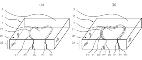
分割線21は、ガラス部材2を、切り離すべき部分片4と残留すべき主部3とに完全に分けるように規定されている。
A dividing
図1には、複数の異なる分割線21の例が示されている。図1aは、それ自体では閉じていない、曲線の非直線の分割線を示している。図1b~図1dは、それ自体で閉じた種々の形状の分割線21を示している。図1bは楕円形の分割線21を示しており、図1cは正五角形の形状の分割線21を示しており、図1dは、正五角形の角を丸めた形状の分割線21を示している。
An example of a plurality of
図2は、ガラス部材2の主部3の領域を加熱するための加熱装置5の一例の概略的な斜視図である。見やすくするため、ガラス部材2は図2では、加熱装置5から顕著な距離にある。実際には、これとは異なってガラス部材2を加熱装置5に接触させることができる。したがって、面状のガラス部材2の下面の表面を加熱装置5上に載置することができる。
FIG. 2 is a schematic perspective view of an example of a
図2では面状のガラス部材2は、図示されたx次元とy次元とにおいて最長寸法を有する。ガラス部材2の最長寸法に沿って延在するこれらの両次元は、「第1の横方向次元6」および「第2の横方向次元7」とも称することとする。横方向次元6,7に対して直交する次元において、ガラスは厚さ23を有する。
In FIG. 2, the
図2に一例として示されている加熱装置5は面状に構成されているので、「加熱プレート」とも称することができる。加熱プレートの表面は、ガラス部材2の両横方向次元6および7に対して平行、すなわち、図2に示されているx次元およびy次元に対して平行である。
The
加熱プレートはガラス部材2の主部3の領域を加熱する。一般的に、上記一例の加熱装置に限定されることなく、加熱プレートは、主部3の形状に適合された加熱場50を有することができる。図示の実施例では、加熱場は第1の横方向次元6において値x=0から値x=x3まで延在し、かつ、第2の横方向次元7において値y=0から値y=y2まで延在しており、その中心には、部分片4に適合された切抜部が設けられており、たとえば値y=y1の場合、加熱場はx=x1からx=x2まで及ぶ。よって、ガラス部材2の、両横方向次元(x次元およびy次元)の平面内に延在する表面は、当該表面における位置(x値およびy値)に依存して異なる温度にさらされる。
The heating plate heats the area of the
図3は、主部3からの部分片4の本発明の分割を行うために適した、ガラス部材2における複数の異なる概略的な温度プロファイルを示している。これらの温度プロファイルは、第2の横方向次元7の値が固定値y=y1である場合の、第1の横方向次元6の位置xの関数として示されている。第2の横方向次元の固定値y=y1は、第1の横方向次元における値xの推移について、主部3の領域における位置および部分片4の領域における位置の双方が現れるように選択されている。図3aは、主部3の温度が一定であり、かつ、部分片4の温度より高い場合の、理想的な温度プロファイルを示している。図3cは、分割線21によって描出された規定破損箇所を経由する温度勾配が存在する場合の、類似の温度プロファイルを示している。図3bおよび図3dも、温度勾配が存在する場合の温度プロファイルを示しており、この温度勾配は、完全に部分片4ないしは主部3の中で推移している。図3a~図3dに示されている温度プロファイル全てに共通する点は、主部3における平均温度が部分片4における平均温度より高いことである。ここでは、ガラス部材2の主部3の領域を加熱したか、または部分片4の領域を冷却したか、または双方を同時もしくは時間シフトして行ったかは、重要ではない。本発明の方法において決定的に重要なのは、このようにして生じた温度プロファイルによってガラス部材2の主部3の領域が膨張し、および/または部分片4の領域が圧縮することのみである。
FIG. 3 shows a number of different schematic temperature profiles in the
図4は、本発明の加熱および/または冷却によってガラス部材2に引張応力が生じた、当該ガラス部材2の平面図、すなわち、クリービング工程を行わなかった場合のガラス部材2の平面図である。引張応力は矢印によって概略的に示されている。ガラス部材2には既に、分割線21に沿って整列された複数の線条状の傷が既に入れられているものとする。図4aは、図3dに示された温度プロファイルに従ってなされたガラス部材2の主部3の領域の加熱に起因する引張応力を示している。図4bは、図3cに示された温度プロファイルに従ってなされた主部3の領域の加熱に起因する引張応力を示している。図4cは、図3bに示された温度プロファイルに従ってなされた部分片4の領域の冷却に起因する引張応力を示している。図4dは、図3cに示された温度プロファイルに従ってなされた部分片4の領域の冷却に起因する引張応力を示している。図4eは、図3dに示された温度プロファイルに従ってなされた主部3の領域の加熱と、それと同時または時間シフトして、図3bに示された温度プロファイルに従ってなされた部分片4の領域の冷却とに起因する、引張応力を示している。図4fは、図3cに示された温度プロファイルに従ってなされた主部3の領域の加熱と、それと同時または時間シフトして、図3bに示された温度プロファイルに従ってなされた部分片4の領域の冷却とに起因する、引張応力を示している。図4gは、図3dに示された温度プロファイルに従ってなされた主部3の領域の加熱と、それと同時または時間シフトして、図3cに示された温度プロファイルに従ってなされた部分片4の領域の冷却とに起因する、引張応力を示している。図4hは、図3cに示された温度プロファイルに従ってなされた主部3の領域の加熱と、それと同時または時間シフトして、図3cに示された温度プロファイルに従ってなされた部分片4の領域の冷却とに起因する、引張応力を示している。
FIG. 4 is a plan view of the
図4a~図4hに示された、加熱および/または冷却によってガラス部材2に引張応力を生じさせるための態様は全て、分割線21に沿って、隣り合った線条状の傷において部分片4が主部3から切り離されることを引き起こすことができる。
All of the embodiments shown in FIGS. 4a-4h for inducing tensile stresses in the
図5は、主部3の領域において加熱されて膨張したガラス部材2の概略的な斜視図である。ガラス部材2の部分片4は、分割線に沿って、隣り合った線条状の傷において主部3から引き離されている。このことにより、部分片4を主部3から取り出すことができる。
FIG. 5 is a schematic perspective view of the heated and expanded
主部3が未だ加熱されている限りにおいては、部分片4の取り出しは問題ない。すなわち、特に主部3に引っ掛かったり、部分片4の破壊または永久変形を伴うことなく、部分片4を取り出すことができる。その根拠は、部分片4に対する主部3の相対的な膨張によって分割線に沿って切り離しがなされるだけでなく、主部3と部分片4との間に、分割線の形状に応じたギャップ24も生じているからである。このギャップは、主部3に引っ掛かることなく部分片4を取り出せるようにするためのある程度の遊びを提供するものである。
As long as the
曲げモーメントを加えることにより働く分割手法、または、たとえばCO2レーザ等のレーザ放射によって局所的に加熱することにより働く分割手法では、ガラス部材2が厚くなるほど困難さが一層増大していくが、本発明の方法では部分片4の取り出しは、特に、厚さ23が少なくとも2mmのガラス部材2、有利には少なくとも3mm、特に有利には少なくとも4mm、さらに有利には少なくとも5mmの厚さ23のガラス部材2にも、問題なく行うことができる。
The splitting method that works by applying a bending moment or the splitting method that works by locally heating by laser radiation such as a CO 2 laser becomes more difficult as the
主部3の領域の加熱および/または部分片4の領域の冷却によって生じるギャップの幅は、特に、主部3と部分片4との間に生じる平均温度の差に依存する。ギャップ幅はまた、両横方向次元6および7における部分片4の面の大きさにも依存する。本発明の方法について有利なのは、部分片4がこれら両次元においてある程度の最低限寸法を有すること、特に、部分片4の第1の横方向次元6における最小寸法および部分片4の第2の横方向次元7における最小寸法が、それぞれ最低限の長さを有することである。本発明の一発展形態では、この最低限の長さは5mm、有利には10mm、特に有利には20mmである。
The width of the gap caused by heating in the area of the
これに代えて、横方向次元6および7によって定まる平面内において部分片4を包囲する最小方形が、それぞれ最低限の長さを有する側辺長41および42を有することも可能である。その際には、部分片4の第1の横方向次元6における最大寸法および当該部分片4の第2の横方向次元7における最大寸法の双方が、それぞれ最低限の長さを有する。
Alternatively, it is also possible that the smallest rectangle enclosing the
図6は、分割線21、および対応する主部3ならびに部分片4の種々の形状のガラス部材2の平面図である。主部3から部分片4を無傷で切り離すこと(すなわち、主部3および部分片4が双方とも、分割エッジのマイクロパーフォレーションを除いて他に傷を負わないように行われる切り離し)は、分割線21が図6aに示されているように直線である場合、簡単に行うことができる。かかる場合、無傷の切り離しは本発明の方法を用いて行うことができるが、たとえば十分な曲げモーメントを加える等の従来の分割手法を用いても行うことができる。たとえば図6bないしは図6cに示されたような、僅かな曲線または僅かに角張った形状の分割線21についても、同様のことが当てはまる。
FIG. 6 is a plan view of the various shapes of the
慣用されている分割手法では特に、分割線21がきつい曲線の場合、または角がきつい形状の場合、すなわち、図6dないしは図6eに例示されているように部分片4がガラス部材2の平面において「大部分が内側」または「完全に内側」にあるといえる場合、問題となる。それに対して、本発明の方法はかかる場合に非常に適している。
In customary splitting techniques, especially if the
図6dは、部分片4の大部分がガラス部材2の内側にある事例を示している。本事例で使用される判断基準は、ガラス部材2の平面における主部3の2次元形状が、数学的トポロジーでいうところの星形ではないことである。つまり、主部3に相当する2次元の領域内には、星点の性質を有する点31が1つも存在しない、ということである。同図中の点31について星点の性質が欠けている理由は、この点31からは、主部3に相当する2次元の領域内の他の点であって、完全に当該2次元の領域内に収まっている他の点全てまで、直線の接続区間を引くことができないからである。よって、点31からは、主部3の領域内の陰影で示された領域には、上述のようにして達することはできない。よって、主部3の領域は星形ではない。図6eに示された主部3の領域についても同様のことが当てはまり、これは星形でもなく、また単純に一続きでもない。この部分片4は完全に内側に収まっている。すなわち、部分片4はガラス部材2の平面において完全に包囲されている。このように内側に収まった部分片4は、「内側輪郭」または「内側幾何形状」と称されることもある。
FIG. 6d shows the case where most of the
本発明の方法について通常有利となるのは、ガラス部材2の平面における部分片4の2次元形状が星形である場合、すなわち、部分片4が、当該部分片4に相当する2次元の領域において少なくとも1つの星点43を有する場合である。このことは、図6dおよび図6eに示された状況に当てはまる。図6dおよび図6eに示された実施例では、部分片4の領域のどの点も星点となる。換言すると、これらの実施例では、部分片4の領域は凸形の領域にもなる。部分片4が面状のガラス部材2の平面において凸形の領域となる場合、切り離しのために有利となる。よって、図示されている実施例に限定されることなく一般的には、本発明の一発展形態では、面状のガラス部材の平面において凸形の領域の2次元形状を有する部分片を引き離す。
It is generally advantageous for the method of the invention if the two-dimensional shape of the
しかし、本発明の方法を機能させるためには、必ずしも、ガラスの面内における部分片の形状を星形または凸形とする必要はない。それは、切り離しが所定の部分において一旦開始すると、この切り離しは、分割線21に従った形状の規定破損箇所に沿って進行する傾向にあることに拠る。さらに、主部3および/または部分片4の不均一な冷却および/または加熱も、非星形の部分片4の切り離しに同様に寄与することができる。
However, it is not necessary for the in-plane portion of the glass to be star-shaped or convex in shape for the method of the present invention to work. This is due to the fact that once detachment begins at a given portion, the detachment tends to proceed along the prescribed breakage point of the shape following the
主部も部分片4もガラスの面内において星形または凸形でないもう1つの事例を、図6fに示す。同図では、ガラス部材2に相当する2次元の領域は星形でなく、また凸形でもなく、また単純に一続きでもない。孔を有するかかるガラス部材2は、たとえば、図6eに示されたように内側に収まった部分片を本発明により切り離すことにより得ることができるものである。この場合、分割線21はそれ自体で閉じている。数学的にいうと、この分割線21によって定まる部分片4は、もはや内側の部分片4ではない。しかし実際には、(孔の大きさ如何によっては)「内側幾何形状」といってもおかしくはない。非星形であり、かつ単純に一続きではない部分片4は、本発明の方法によって無傷で、かつ、非星形であって単純に一続きでない主部3から引っ掛かることなく切り離すことができる。
Another case in which neither the main part nor the
図7aを見ると明らかであるように、本発明の一発展形態では、面法線14とレーザパルス12の向きとの間に角度が生じるように、レーザパルス12の向きをガラス部材2の表面22に対して斜めにすることもできる。このことにより、線条状の傷20の長手方向も表面22に対して斜めに延在することとなる。さらに留意すべき点は、ガラス部材2の表面22におけるレーザ光の屈折の影響である。
As can be seen in FIG. 7a, in a development of the invention the
光入射方向と面法線14との間の角度は、部分片の切り離しを容易にするため、数度から10°を有意に上回る角度までの範囲内とすることができる。有利には、レーザパルス12の光入射方向とガラス部材2の表面22の面法線14との間の角度を、3°~30°の範囲内、特に有利には3°~15°の範囲内、さらに有利には少なくとも5°に調整する。
The angle between the direction of light incidence and the surface normal 14 can range from a few degrees to an angle significantly greater than 10° to facilitate separation of the pieces. Advantageously, the angle between the light incidence direction of the
図7aを見ると分かるように、さらに、光入射平面15が分割線21と交差するように、有利には分割線21に対して垂直となるように、レーザパルス12の向きを表面22に対して斜めにする。このことに応じて、入射点13が表面22上を移動する送り方向も、光入射平面15と交差し、有利には光入射平面15に対して垂直となる。光入射平面15は、光入射方向と面法線14とによって定まる。分割線21が図示の実施例のように曲線である場合、たとえば円形である場合には、分割線21の向きが光入射平面15と交差するとは、分割線21における接線が光入射平面15と交差し、有利には光入射平面15に対して垂直であることをいう。
As can be seen in FIG. 7a, the
図7bは、ガラス部材2の、図7aに対応する断面図である。線条状の傷20の長手方向と表面22の法線との間の角度によって、部分片4を主部3から分離する送り方向が、矢印によって示されている方向となる。
FIG. 7b is a cross-sectional view of the
図8は、レーザ加工を複数回、それぞれ異なる焦点深度で行った後のガラス部材の、図7bに類する断面図である。つまり、レーザパルス12の入射点13をガラス部材2上において分割線21に沿って表面22にわたって移動させることにより、超短パルスレーザのレーザパルス12によってガラス部材2の体積に傷20を形成する加工工程後に、同様の手法であるが、レーザパルス12の焦点深度を変えて、ガラス部材2の体積に別の深さで傷20’,20’’等を形成する他の加工工程がある、ということである。
FIG. 8 is a cross-sectional view similar to FIG. 7b of a glass member after multiple laser machining operations, each with a different depth of focus. That is, by moving the
かかる複数回のレーザ加工は特に、比較的厚いガラス部材2であって、1加工工程で、ないしは分割線21に沿ってレーザビーム12の入射点13を1回移動するだけで、全厚23にわたってマイクロパーフォレーションを行うことができなくなるか、または少なくとも不都合になることが多いガラス部材2の場合に好適である。
Such multiple laser machining is particularly useful for relatively
レーザビームを複数回それぞれ異なる焦点深度で通過する場合に生じる問題は、ガラス部材2の体積のそれぞれ異なる深さの複数の傷が理想的に揃わない、ということである。
A problem that arises when passing the laser beam multiple times with different focal depths is that the scratches of different depths in the volume of the
図8aに、表面22においてレーザ加工を2回行った後のガラス部材2を概略的に例示する。1回目の加工工程では傷20を形成し、2回目の工程では、その下の深さに傷20’を形成した。傷20と20’とは、相互間にある程度のオフセットを有し、このオフセットは典型的には、位置精度が有限であることに起因して統計的なばらつきを有する。このオフセットにより、本発明の方法によって部分片4を主部3から切り離すことが困難になる。このオフセットによって、線条形成自体に起因する粗さRより大きい、カットエッジの粗さR’が生じる。
FIG. 8a schematically illustrates the
本発明の一発展形態では、主部3からの部分片4の切り離しについては線条形成自体に起因する粗さRのみが決定要因となり、オフセットを考慮した、エッジ面の粗さR’は決定要因とならないように、傷20と20’との間のオフセットを引き起こす。
In a development of the invention, the detachment of the
図8bに示されているように、表面22からガラス部材2の体積内により深い位置にある傷20’は、部分片4の表面22とは反対側の面の方が、表面22側の面より若干大きくなるように形成されている。このことによって、部分片4を主部3から分離する送り方向が、矢印によって示されている方向となる。この送り方向においては、線条形成にのみ起因する粗さRが切り離しの決定要因となるのに対し、送り方向とは逆方向においては、傷20と20’との間のオフセットによっても生じる粗さR’が、切り離しの決定要因となる。部分片4は完全に内側に収まった部分片である必要はなく、むしろ、既に述べた全ての形状とすることができる。部分片4が円形の内側片である場合には、部分片4は傷20と20’との間のオフセットに起因して、絵的にいうとケーキ形を有する。
As shown in FIG. 8b, a flaw 20' located deeper in the volume of the
図1の傷20は、レーザパルス12の入射点13をガラス部材2上において分割線21に沿って表面22にわたって移動させることによって形成されるのに対し、図9aの傷20’は、分割線21から僅かに離隔したオフセット線21’に沿ってレーザパルス12の入射点13をガラス部材2上において表面22にわたって移動させることによって形成される。有利には、オフセット線の全部が分割線21の片側に延在するが、オフセット線21’から分割線21までの距離が当該線にわたって一定であることは、有利ではあっても、必ずしも必須ではない。
The
本発明の上述の発展形態は、2回のレーザ加工に限定されるものではない。レーザを3回またはそれ以上の回数で通過することも可能である。図8cに、レーザ加工を3回行った後のガラス部材2の断面を概略的に例示しており、この3回のレーザ加工によって傷20,20’および20’’が生じている。図8dの方では、主部3から部分片4を切り離すための送り方向が、矢印によって示された方向になるようにするためには、本発明の本発展形態において傷20と20’との間のオフセット、および、傷20’と20’’との間のオフセットをどのようにして形成できるかを示している。
The above-described development of the invention is not limited to two laser processes. Three or more passes through the laser are also possible. FIG. 8c schematically illustrates a cross-section of the
図9bの傷20’は、ガラス部材2におけるレーザパルス12の入射点13を分割線21から僅かに離隔した第1のオフセット線21’に沿って表面22にわたって移動させることによって形成される。さらに、傷20’’は、ガラス部材2におけるレーザパルス12の入射点13を、分割線21からの距離が第1のオフセット線21’より遠い第2のオフセット線21’’に沿って表面22にわたって移動させることによって形成される。有利には、第2のオフセット線21’’の全部が第1のオフセット線21’の片側に延在するが、第2のオフセット線21’’から第1のオフセット線21’までの距離が当該線にわたって一定であることは、有利ではあっても、必ずしも必須ではない。
The flaw 20' of FIG. 9b is produced by moving the point of
レーザ加工の2工程より多くの工程を実施することも可能である。こうするためには、ガラス部材2におけるレーザパルス12の入射点13を表面22にわたって移動させる、さらに他のオフセット線を規定することができ、この他のオフセット線も、分割線21から若干遠くに離隔している。
It is also possible to perform more than two steps of laser processing. To do this, a further offset line can be defined that moves the point of
複数回異なる焦点深度でレーザ加工を行うことにより形成される傷間の1つのオフセットまたは複数のオフセットの上述の意図的なコントロールは、図7に示されている、レーザパルス12の向きをガラス部材2の表面22に対して斜めにするレーザ加工と、組み合わせることができる。実際には、光入射方向と面法線14との間の角度は、通常は正確に0°に調整することができない。よって、厳密には通常は(たとえそうでも)小さい角度が生じるので、通常は、傷チャネルの長手方向とガラス部材2の面法線14との間にはある程度の角度が生じる。この調整の場合にも、位置決めのときと同様、方向精度より小さい統計的な偏差が想定される。
The above-described intentional control of the offset or offsets between flaws created by laser machining at multiple different depths of focus can be achieved by directing the
図8eは、ガラス部材2を2回レーザ加工したことによる斜めの傷20および20’を示している。同図でも、傷20と20’とは厳密に1つの線上にはなく(ないしは、厳密に1つの面内にはなく)、相互間にある程度のオフセットを有する。このことによっても、本発明の方法によって部分片4を主部3から切り離すことが困難になる。
FIG. 8e shows
しかし図8fに示されているように、このオフセットは有利には、切り離しのための送り方向が矢印によって示されている方向になるように調整することができる。送り方向とは逆方向において、オフセットによって生じたエッジが妨害となって作用することなく、部分片4を主部3から切り離すことができる。
However, as shown in FIG. 8f, this offset can advantageously be adjusted so that the feed direction for uncoupling is in the direction indicated by the arrow. In a direction opposite to the feed direction, the
本発明の上述の発展形態は、レーザパルス12を表面22に斜めに入射させて2回行われるレーザ加工にのみ限定されるものではない。レーザ加工工程を3回またはそれ以上の回数で異なる焦点深度で行うことも可能である。図8gに、レーザパルス12の向きを表面に対して斜めにしてレーザ加工を3回行った後のガラス部材2の断面を概略的に例示しており、この3回のレーザ加工によって傷20,20’および20’’が生じている。図8hの方では、主部3から部分片4を切り離すための送り方向が、矢印によって示された方向になるようにするためには、本発明の本発展形態において傷20と20’との間のオフセット、および、傷20’と20’’との間のオフセットをどのようにして配置できるかを示している。これらのオフセットは、実用上は等しい大きさである必要はない。
The above-described development of the invention is not limited to laser machining in which the
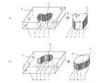
図10は、本発明の方法により製造可能な、それぞれ2つの面状のガラス部材から成る2つのセット(図10aおよび図10b)を示している。図10bに示されている、2つの面状のガラス部材から成るセットは、一方の面状のガラス部材2の平面内における当該一方の面状のガラス部材2の2次元の形状が、他方の面状のガラス部材2’の平面内における当該他方の面状のガラス部材2’の2次元の形状を完全に包囲するように構成されているのに対し、図10aに示されている、2つの面状のガラス部材2から成るセットについては、そうではない。具体的には図10bに示されているセットについては、ガラス部材2’が、ガラス部材2に嵌合する内側片である、ということである。つまり、図10aに示されているセットについては、ガラス部材2’が、ガラス部材2に嵌合する部分片であり、これは、「大部分が内側にある」ということができる。
FIG. 10 shows two sets (FIGS. 10a and 10b) each of two planar glass elements that can be produced by the method of the invention. A set of two
図示の両セット(図10aおよび図10b)については、双方共に、一方の面状のガラス部材2が少なくとも理論的には、他方の面状のガラス部材2’とぴったり接合することが可能であることが適用される。
For both sets shown (FIGS. 10a and 10b), it is possible, at least in theory, for one
1つのセットのいずれの面状のガラス部材2(または2’)も、並んで延在する複数の線条状の傷26(または26’)が設けられたエッジ面25(または25’)を有し、これらの線条状の傷26(または26’)は、当該エッジ面25(または25’)において窪部を形成する。線条状の傷は、本発明の方法によるマイクロパーフォレーションレーザ加工によって得ることができる。 Any planar glass member 2 (or 2') of a set has an edge surface 25 (or 25') provided with a plurality of linear scratches 26 (or 26') extending side by side. These striated blemishes 26 (or 26') form depressions in the edge surface 25 (or 25'). Striated scratches can be obtained by microperforation laser processing according to the method of the present invention.
2つの面状のガラス部材を有するセットの1つの面状のガラス部材のエッジ面25(または25’)にある線条状の傷26(または26’)の長手方向は、ガラス部材の各面29(または29’)および30(または30’)と当該エッジ面25(または25’)との間の移行部となる一方のエッジから他方のエッジへ向かう方向に延在している。2つのガラス部材のセットのうち1つのガラス部材2(または2’)を本発明の方法によって製造する場合、線条状の傷26(または26’)の長手方向は、レーザパルスの光伝播方向に相当する。 The longitudinal direction of the linear scratches 26 (or 26') on the edge surface 25 (or 25') of one planar glass member of a set with two planar glass members It extends in the direction from one edge to the other edge which is the transition between 29 (or 29') and 30 (or 30') and the edge surface 25 (or 25'). When one glass member 2 (or 2') of a set of two glass members is produced by the method of the present invention, the longitudinal direction of the linear flaw 26 (or 26') is the direction of light propagation of the laser pulse. corresponds to
1つのセットの両面状のガラス部材2および2’をぴったり接合すると、両ガラス部材2および2’のエッジ面25および25’は互いに接触し、または互いに非常に近接することとなる。また、エッジ27および27’も互いに接触し、または互いに非常に近接することとなり、さらに、エッジ28および28’も互いに接触し、または互いに非常に近接することとなる。両ガラス部材2および2’を接合すると、両面状のガラス部材2および2’の平面内における2次元の面は、2つのパズルピースのように符合する。
When a set of two-
有利には、1つのセットの両面状のガラス部材は、同一の切り離しプロセスから得られたものである。具体的には、本発明の方法を使用して、元の1つの面状のガラス部材を主部と部分片とに分割し、これらが合わさって、面状のガラス部材の本発明の1セットを構成する、ということである。1セットの両面状のガラス部材が同一のプロセスから得られたものである場合には、特に非常に高い嵌合精度を保証することができ、また、複数の同等の切り離しプロセスから、互いに同等の複数の部分片の部分片ロットと、互いに同等の複数の主部の主部ロットとを作製する場合であって、部分片ロットのいずれか任意の部分片と主部ロットのいずれか任意の主部とから、面状のガラス部材の本発明の1セットを構成する場合より、嵌合精度が一層高くなる。 Advantageously, a set of double-sided glass members are obtained from the same separating process. Specifically, using the method of the present invention, an original single planar glass member is divided into main portions and partial pieces which together form an inventive set of planar glass members. is to constitute A very high fitting accuracy can be ensured, especially if a set of double-sided glass members are obtained from the same process, and a plurality of identical detachment processes can result in identical When producing a partial piece lot of a plurality of partial pieces and a main lot of a plurality of main parts equivalent to each other, any partial piece of the partial piece lot and any main of the main lot The fitting precision is higher than in the case where one set of the planar glass member of the present invention is constructed from the parts.
本発明の一発展形態では、2つの面状のガラス部材を有する1セットの各面状のガラス部材2(または2’)が、少なくとも1つのオフセット32(または32’)すなわち段部があるエッジ面25(または25’)を有し、この少なくとも1つのオフセット32(または32’)は、並んで延在する線条状の傷26(または26’)の長手方向と交差し、有利には実質的に垂直に延在する。かかる面状のガラス部材2のイメージを、図11に示す。
In a development of the invention, each sheet glass element 2 (or 2') of a set with two sheet glass elements has at least one offset 32 (or 32') or edge with a step. It has a surface 25 (or 25') which at least one offset 32 (or 32') intersects the longitudinal direction of the side-by-side extending linear scratches 26 (or 26') and advantageously extending substantially vertically; An image of such a
少なくとも1つのオフセット32(または32’)によって、エッジ面25(または25’)に、線条状の傷26(または26’)に起因する粗さRより大きい粗さR’を生じさせることができる。 At least one offset 32 (or 32') can cause the edge surface 25 (or 25') to have a roughness R' that is greater than the roughness R caused by the streak 26 (or 26'). can.
少なくとも1つのオフセットは、肉眼では知覚できない段部となるので、引き続き「単一のエッジ面25(または25’)」ということができる。有利には、少なくとも1つのオフセットは、少なくとも5μmかつ最大50μmの段部となる。 At least one offset will result in a step that is imperceptible to the unaided eye, and thus can continue to be referred to as "single edged surface 25 (or 25')". Advantageously, the at least one offset amounts to a step of at least 5 μm and at most 50 μm.
図11aに示す本発明の面状のガラス部材2が特徴とする点は、エッジ面25において並んで延在する複数の線条状の傷26が設けられており、これらの線条状の傷26はエッジ面25の窪部を成し、線条状の傷26の長手方向は、当該面状のガラス部材2の各面30とエッジ面25との間の移行部となる一方のエッジ27から他方のエッジ28へ向かう方向に延在し、エッジ面25は、当該エッジ面25全体に沿って延在するオフセット32を有し、当該オフセットは、線条状の傷26の長手方向に対して実質的に垂直に延在することである。オフセットは有利には、エッジ面の中央において20%の偏差で、すなわち、エッジ27と28との間の中央において20%の偏差で延在する。
A feature of the
図11bは、本発明の他の面状のガラス部材2を示しており、この面状のガラス部材は、エッジ面25が当該エッジ面25全体に沿って延在する2つのオフセット32を有し、これらのオフセット32は、線条状の傷26の長手方向に対して実質的に垂直に延在する。これら両オフセットは有利には、ガラス部材2の表面30からエッジ面25の幅23の1/3または2/3の距離に20%の偏差で延在する。
FIG. 11b shows another
1 レーザ加工装置
10 超短パルスレーザ
11 集光装置
12 レーザパルス
13 ガラス部材におけるレーザパルスの入射点
14 ガラス部材の面法線
15 レーザパルスの光入射平面
2 面状のガラス部材
2’ 面状のガラス部材
20,20’,20’’ 線条状の傷
21,21’,21’’ 分割線
22 ガラス部材の表面
23 ガラス部材の厚さ
24 部分片と主部との間のギャップ
25 並んで延在する線条状の傷が存在するエッジ面
25’ 並んで延在する線条状の傷が存在するエッジ面
26 エッジ面の線条状の傷
26’ エッジ面の線条状の傷
27,28 面状のガラス部材の、各面と当該各面を接続するエッジ面との間の移行部を成すエッジ
27’,28’ 面状のガラス部材の、各面と当該各面を接続するエッジ面との間の移行部を成すエッジ
29,30 面状のガラス部材の面
29’,30’ 面状のガラス部材の面
32 エッジ面におけるオフセット
3 主部
31 主部に相当する2次元の領域内の1点
4 切り離すべき部分片
41 第1の横方向次元における部分片の最大広がり
42 第2の横方向次元における部分片の最大広がり
43 部分片に相当する2次元の領域内の1点
5 加熱装置
50 加熱場
6 ガラス部材の第1の横方向次元
7 ガラス部材の第2の横方向次元
REFERENCE SIGNS LIST 1 laser processing device 10 ultrashort pulse laser 11 focusing device 12 laser pulse 13 laser pulse incident point on glass member 14 surface normal of glass member 15 laser pulse light incident plane 2 planar glass member 2′ planar Glass member 20, 20', 20'' Striation 21, 21', 21'' Parting line 22 Surface of glass member 23 Thickness of glass member 24 Gap 25 between piece and main part Side by side Edge surface 25' with linear flaws extending side by side Edge surface 26 with linear flaws extending side by side Linear flaws on edge surface 26' Linear flaws on edge surface 27 , 28 edges forming a transition between each face of the planar glass member and edge faces connecting the faces 27 ′, 28 ′ connecting the faces of the planar glass member and the respective faces Edges 29, 30 Surfaces 29′, 30′ of the planar glass member 32 Offset on the edge surface 3 Principal portion 31 A two-dimensional surface corresponding to the principal portion 1 point in the region 4 piece to be separated 41 maximum extent of the piece in the first horizontal dimension 42 maximum extent of the piece in the second horizontal dimension 43 point in the two-dimensional region corresponding to the piece 5 heating device 50 heating field 6 first lateral dimension of glass member 7 second lateral dimension of glass member
Claims (8)
前記ガラス部材(2)の体積に線条状の傷(20)を前記分割線(21)に沿って並べて形成し、
前記傷(20)を超短パルスレーザ(10)のレーザパルス(12)によって形成し、前記ガラス部材(2)の材料は、前記レーザパルス(12)に対して透過性であり、
前記レーザパルス(12)は、前記ガラス部材(2)の体積においてプラズマを生成し、前記プラズマは、前記線条状の傷(20)を形成し、
前記ガラス部材(2)上における前記レーザパルス(12)の入射点(13)を前記ガラス部材(2)の表面(22)上において前記分割線(21)に沿って移動させ、
前記分割線(21)に沿って並んで配置された前記線条状の傷(20)を入れた後、前記部分片(4)と前記主部(3)とをそれぞれ完全体として維持しながら、並んだ前記線条状の傷(20)において前記部分片(4)を前記分割線(21)に沿って前記主部(3)から引き離すように、前記ガラス部材(2)の前記主部(3)の領域を加熱して膨張させ、および/または、前記ガラス部材(2)の前記部分片(4)の領域を冷却して圧縮させ、
前記面状のガラス部材の一方の面状のガラス部材(2)の平面における前記一方の面状のガラス部材(2)の2次元形状は、前記面状のガラス部材の他方の面状のガラス部材(2’)の平面における前記他方の面状のガラス部材(2’)の2次元形状に対して相補的であり、
各面(29,30)と、前記各面(29,30)を接続するエッジ面(25)と、の間の移行部を成す、前記一方の面状のガラス部材(2)の2つの各エッジ(27,28)は、各面(29’,30’)と、前記各面(29’,30’)を接続するエッジ面(25’)と、の間の移行部を成す、前記他方の面状のガラス部材(2’)の2つのエッジ(27’,28’)と同一形状を有し、
前記2つの面状のガラス部材(2,2’)の前記各エッジ面(25,25’)にそれぞれ、並んで延在する複数の線条状の傷(26,26’)が設けられており、前記複数の線条状の傷(26,26’)は、前記エッジ面(25,25’)の窪部を成し、
前記線条状の傷(26,26’)の各長手方向はそれぞれ、一方のエッジ(27,27’)から他方のエッジ(28,28’)へ向かう方向に延在し、
前記エッジ面(25,25’)の平均粗さRは、L・ΔT・αより小さく、
Lは、前記面状のガラス部材の平面における前記部分片の最小寸法であり、
ΔTは、前記主部の平均温度と前記部分片の平均温度との間に生じる温度差であり、
αは、前記ガラス部材の材料が有する熱膨張係数である、
2つの面状のガラス部材(2,2’)を有するセット。 Along the predetermined dividing line (21) dividing the planar glass member (2) into the partial piece (4) to be cut off and the main portion (3) to be left, the partial piece ( A set comprising two planar glass members (2, 2') producible using the method of separating 4), said method comprising:
Forming linear scratches (20) in the volume of the glass member (2) along the dividing line (21),
said flaw (20) being formed by a laser pulse (12) of an ultrashort pulse laser (10), the material of said glass member (2) being transparent to said laser pulse (12);
said laser pulse (12) generates a plasma in the volume of said glass member (2), said plasma forming said filamentary flaw (20),
moving the incident point (13) of the laser pulse (12) on the glass member (2) along the dividing line (21) on the surface (22) of the glass member (2);
After making the linear scratches (20) arranged side by side along the parting line (21), while maintaining the partial piece (4) and the main part (3) as a whole. , the main portion of the glass member (2) so as to separate the partial piece (4) from the main portion (3) along the parting line (21) at the aligned linear scratches (20). heating the region of (3) to expand and/or cooling and compressing the region of said partial piece (4) of said glass member (2);
The two-dimensional shape of the one planar glass member (2) in the plane of the one planar glass member (2) of the planar glass member is the other planar glass member of the planar glass member. complementary to the two-dimensional shape of said other planar glass member (2') in the plane of the member (2');
two each of said one planar glass member (2) forming a transition between each face (29, 30) and an edge face (25) connecting said faces (29, 30) Edges (27, 28) form a transition between each face (29', 30') and an edge face (25') connecting said faces (29', 30'), said other having the same shape as the two edges (27', 28') of the planar glass member (2') of
A plurality of linear scratches (26, 26') extending side by side are provided on the respective edge surfaces (25, 25') of the two planar glass members (2, 2'). and the plurality of linear scratches (26, 26') form depressions in the edge surfaces (25, 25'),
each longitudinal direction of the linear scratches (26, 26') respectively extends in a direction from one edge (27, 27') to the other edge (28, 28') ;
The average roughness R of the edge surface (25, 25') is smaller than L ΔT α,
L is the minimum dimension of the partial piece in the plane of the planar glass member;
ΔT is the temperature difference between the average temperature of the main portion and the average temperature of the partial piece;
α is the coefficient of thermal expansion of the material of the glass member,
A set with two planar glass elements (2, 2').
請求項1記載の2つの面状のガラス部材(2,2’)を有するセット。 The two-dimensional shape of the one planar glass member (2) in the plane of the one planar glass member (2) is the other surface in the plane of the other planar glass member (2'). completely enclosing the two-dimensional shape of the shaped glass member (2'),
A set comprising two planar glass elements (2, 2') according to claim 1.
請求項1または2記載の2つの面状のガラス部材(2,2’)を有するセット。 The one planar glass member (2) is heat-strengthened,
A set comprising two planar glass elements (2, 2') according to claim 1 or 2.
請求項1から3のいずれか記載の2つの面状のガラス部材(2,2’)を有するセット。A set comprising two planar glass elements (2, 2') according to any of claims 1-3.
請求項1から4のいずれか記載の2つの面状のガラス部材(2,2’)を有するセット。A set comprising two planar glass elements (2, 2') according to any one of claims 1 to 4.
前記ガラス部材(2)の体積に線条状の傷(20)を前記分割線(21)に沿って並べて形成し、
前記傷(20)を超短パルスレーザ(10)のレーザパルス(12)によって形成し、前記ガラス部材(2)の材料は、前記レーザパルス(12)に対して透過性であり、
前記レーザパルス(12)は、前記ガラス部材(2)の体積においてプラズマを生成し、前記プラズマは、前記線条状の傷(20)を形成し、
前記ガラス部材(2)上における前記レーザパルス(12)の入射点(13)を前記ガラス部材(2)の表面(22)上において前記分割線(21)に沿って移動させ、
前記分割線(21)に沿って並んで配置された前記線条状の傷(20)を入れた後、前記部分片(4)と前記主部(3)とをそれぞれ完全体として維持しながら、並んだ前記線条状の傷(20)において前記部分片(4)を前記分割線(21)に沿って前記主部(3)から引き離すように、前記ガラス部材(2)の前記主部(3)の領域を加熱して膨張させ、および/または、前記ガラス部材(2)の前記部分片(4)の領域を冷却して圧縮させ、
前記面状のガラス部材(2)のエッジ面(25)において並んで延在する複数の線条状の傷(26)が存在しており、前記線条状の傷(26)は、前記エッジ面(25)の窪部を成し、
前記線条状の傷(26)の長手方向は、前記面状のガラス部材(2)の各面(30)とエッジ面(25)との間の移行部となる一方のエッジ(27)から他方のエッジ(28)へ向かう方向に延在し、
前記エッジ面(25)は、前記エッジ面(25)全体に沿って延在するオフセット(32)を有し、前記オフセット(32)は、前記線条状の傷(26)の長手方向に対して実質的に垂直に延在し、
前記エッジ面(25)の平均粗さRは、L・ΔT・αより小さく、
Lは、前記面状のガラス部材の平面における前記部分片の最小寸法であり、
ΔTは、前記主部の平均温度と前記部分片の平均温度との間に生じる温度差であり、
αは、前記ガラス部材の材料が有する熱膨張係数である、
面状のガラス部材(2)。 From the planar glass member (2) along a predetermined dividing line (21) that divides the planar glass member (2) into a partial piece (4) to be cut off and a main portion (3) to be retained. A planar glass member (2) producible using a method of separating partial pieces (4), said method comprising:
Forming linear scratches (20) in the volume of the glass member (2) along the dividing line (21),
said flaw (20) being formed by a laser pulse (12) of an ultrashort pulse laser (10), the material of said glass member (2) being transparent to said laser pulse (12);
said laser pulse (12) generates a plasma in the volume of said glass member (2), said plasma forming said filamentary flaw (20),
moving the incident point (13) of the laser pulse (12) on the glass member (2) along the dividing line (21) on the surface (22) of the glass member (2);
After making the linear scratches (20) arranged side by side along the parting line (21), while maintaining the partial piece (4) and the main part (3) as a whole. , the main portion of the glass member (2) so as to separate the partial piece (4) from the main portion (3) along the parting line (21) at the aligned linear scratches (20). heating the region of (3) to expand and/or cooling and compressing the region of said partial piece (4) of said glass member (2);
There are a plurality of linear scratches (26) extending side by side on the edge surface (25) of the planar glass member (2), and the linear scratches (26) are formed on the edge surface (25). forming a recess in the face (25),
The longitudinal direction of the linear scratches (26) extends from one edge (27) that serves as a transition between each surface (30) of the planar glass member (2) and the edge surface (25). extending in a direction towards the other edge (28),
The edge surface (25) has an offset (32) extending along the entire edge surface (25), the offset (32) being extending substantially vertically through the
The average roughness R of the edge surface (25) is smaller than L ΔT α,
L is the minimum dimension of the partial piece in the plane of the planar glass member;
ΔT is the temperature difference between the average temperature of the main portion and the average temperature of the partial piece;
α is the coefficient of thermal expansion of the material of the glass member,
A planar glass member (2).
請求項6記載の面状のガラス部材(2)。A planar glass member (2) according to claim 6.
請求項6または7記載の面状のガラス部材(2)。A planar glass member (2) according to claim 6 or 7.
Applications Claiming Priority (2)
| Application Number | Priority Date | Filing Date | Title |
|---|---|---|---|
| DE102015111490.9A DE102015111490A1 (en) | 2015-07-15 | 2015-07-15 | Method and device for laser-assisted separation of a section from a flat glass element |
| DE102015111490.9 | 2015-07-15 |
Related Parent Applications (1)
| Application Number | Title | Priority Date | Filing Date |
|---|---|---|---|
| JP2018501293A Division JP6768781B2 (en) | 2015-07-15 | 2016-07-06 | Method and device for separating a piece from a planar glass member by laser assist |
Publications (2)
| Publication Number | Publication Date |
|---|---|
| JP2021006503A JP2021006503A (en) | 2021-01-21 |
| JP7191908B2 true JP7191908B2 (en) | 2022-12-19 |
Family
ID=56368968
Family Applications (2)
| Application Number | Title | Priority Date | Filing Date |
|---|---|---|---|
| JP2018501293A Active JP6768781B2 (en) | 2015-07-15 | 2016-07-06 | Method and device for separating a piece from a planar glass member by laser assist |
| JP2020159097A Active JP7191908B2 (en) | 2015-07-15 | 2020-09-23 | Method and apparatus for laser-assisted separation of partial pieces from planar glass members |
Family Applications Before (1)
| Application Number | Title | Priority Date | Filing Date |
|---|---|---|---|
| JP2018501293A Active JP6768781B2 (en) | 2015-07-15 | 2016-07-06 | Method and device for separating a piece from a planar glass member by laser assist |
Country Status (6)
| Country | Link |
|---|---|
| US (2) | US11572301B2 (en) |
| EP (2) | EP3590898B1 (en) |
| JP (2) | JP6768781B2 (en) |
| CN (1) | CN107848861B (en) |
| DE (1) | DE102015111490A1 (en) |
| WO (1) | WO2017009149A1 (en) |
Families Citing this family (55)
| Publication number | Priority date | Publication date | Assignee | Title |
|---|---|---|---|---|
| EP2754524B1 (en) | 2013-01-15 | 2015-11-25 | Corning Laser Technologies GmbH | Method of and apparatus for laser based processing of flat substrates being wafer or glass element using a laser beam line |
| EP2781296B1 (en) | 2013-03-21 | 2020-10-21 | Corning Laser Technologies GmbH | Device and method for cutting out contours from flat substrates using a laser |
| US10293436B2 (en) | 2013-12-17 | 2019-05-21 | Corning Incorporated | Method for rapid laser drilling of holes in glass and products made therefrom |
| US11556039B2 (en) | 2013-12-17 | 2023-01-17 | Corning Incorporated | Electrochromic coated glass articles and methods for laser processing the same |
| TWI730945B (en) | 2014-07-08 | 2021-06-21 | 美商康寧公司 | Methods and apparatuses for laser processing materials |
| KR20170028943A (en) | 2014-07-14 | 2017-03-14 | 코닝 인코포레이티드 | System for and method of processing transparent materials using laser beam focal lines adjustable in length and diameter |
| US11773004B2 (en) | 2015-03-24 | 2023-10-03 | Corning Incorporated | Laser cutting and processing of display glass compositions |
| WO2017011296A1 (en) | 2015-07-10 | 2017-01-19 | Corning Incorporated | Methods of continuous fabrication of holes in flexible substrate sheets and products relating to the same |
| DE102015111490A1 (en) | 2015-07-15 | 2017-01-19 | Schott Ag | Method and device for laser-assisted separation of a section from a flat glass element |
| DE102015120950B4 (en) | 2015-12-02 | 2022-03-03 | Schott Ag | Method for laser-assisted detachment of a section from a flat glass or glass-ceramic element, flat at least partially ceramized glass element or glass-ceramic element and cooking surface comprising a flat glass or glass-ceramic element |
| JP6938543B2 (en) | 2016-05-06 | 2021-09-22 | コーニング インコーポレイテッド | Laser cutting and removal of contoured shapes from transparent substrates |
| US11419231B1 (en) | 2016-09-22 | 2022-08-16 | Apple Inc. | Forming glass covers for electronic devices |
| US11535551B2 (en) | 2016-09-23 | 2022-12-27 | Apple Inc. | Thermoformed cover glass for an electronic device |
| US11565506B2 (en) | 2016-09-23 | 2023-01-31 | Apple Inc. | Thermoformed cover glass for an electronic device |
| US10800141B2 (en) | 2016-09-23 | 2020-10-13 | Apple Inc. | Electronic device having a glass component with crack hindering internal stress regions |
| US10730783B2 (en) | 2016-09-30 | 2020-08-04 | Corning Incorporated | Apparatuses and methods for laser processing transparent workpieces using non-axisymmetric beam spots |
| KR102428350B1 (en) | 2016-10-24 | 2022-08-02 | 코닝 인코포레이티드 | Substrate processing station for laser-based machining of sheet-like glass substrates |
| DE102017208290A1 (en) | 2017-05-17 | 2018-11-22 | Schott Ag | Apparatus and method for processing a workpiece along a predetermined processing line |
| CN115259646B (en) | 2017-05-19 | 2024-05-17 | 肖特股份有限公司 | Component comprising glass or glass-ceramic and method for producing the component |
| US10689286B2 (en) * | 2017-10-13 | 2020-06-23 | Seagate Technology Llc | Separation of glass shapes using engineered induced thermal gradients after process cutting |
| DE102018100443A1 (en) * | 2018-01-10 | 2019-07-11 | Schott Ag | Process and device for the production of glass precursors and glass products |
| WO2019151185A1 (en) * | 2018-01-31 | 2019-08-08 | Hoya株式会社 | Method for producing glass substrate for magnetic disk |
| US12202759B2 (en) * | 2018-02-26 | 2025-01-21 | Corning Incorporated | Methods for laser forming transparent articles from a transparent mother sheet and processing the transparent articles in-situ |
| DE102018109820A1 (en) | 2018-04-24 | 2019-10-24 | Schott Ag | Process and apparatus for the production of hollow glass body products and hollow glass body products and their use |
| WO2020021705A1 (en) | 2018-07-27 | 2020-01-30 | Hoya株式会社 | Manufacturing method for glass substrate and manufacturing method for magnetic disc |
| CN109095765A (en) * | 2018-09-21 | 2018-12-28 | 杨晓明 | A kind of glass processing device and glass processing method |
| CN109160722A (en) * | 2018-09-21 | 2019-01-08 | 杨晓明 | A kind of glass separation equipment and glass separation method |
| US11420900B2 (en) | 2018-09-26 | 2022-08-23 | Apple Inc. | Localized control of bulk material properties |
| JP2021516159A (en) * | 2019-02-12 | 2021-07-01 | ハンズ レーザー テクノロジー インダストリー グループ カンパニー リミテッド | Processing methods, equipment and systems for hard and brittle material products |
| JP7242362B2 (en) * | 2019-03-18 | 2023-03-20 | キオクシア株式会社 | Semiconductor device manufacturing method |
| DE102019113635A1 (en) | 2019-05-22 | 2020-11-26 | Schott Ag | Method and device for processing glass elements |
| US11680010B2 (en) | 2019-07-09 | 2023-06-20 | Apple Inc. | Evaluation of transparent components for electronic devices |
| DE102019215264A1 (en) * | 2019-10-02 | 2021-04-08 | Flabeg Deutschland Gmbh | Disc-shaped glass element and method for separating a glass substrate into a plurality of such glass elements |
| WO2021100480A1 (en) * | 2019-11-21 | 2021-05-27 | Agc株式会社 | Method for processing glass plate, and glass plate |
| DE112020005047T5 (en) * | 2019-11-21 | 2022-11-03 | AGC Inc. | GLASS PLATE PROCESSING PROCESS AND GLASS PLATE |
| KR20210110510A (en) * | 2020-02-28 | 2021-09-08 | 쇼오트 아게 | Method for separating a glass element and glass sub-element |
| ES2976069T3 (en) | 2020-03-06 | 2024-07-22 | Schott Ag | Procedure for preparing and/or carrying out the separation of a substrate element and a partial substrate element |
| US11460892B2 (en) | 2020-03-28 | 2022-10-04 | Apple Inc. | Glass cover member for an electronic device enclosure |
| CN115955798A (en) | 2020-03-28 | 2023-04-11 | 苹果公司 | Glass cover member for housing of electronic equipment |
| US11666273B2 (en) | 2020-05-20 | 2023-06-06 | Apple Inc. | Electronic device enclosure including a glass ceramic region |
| DE102020123928A1 (en) | 2020-09-15 | 2022-03-17 | Schott Ag | Process and device for cutting glass foils |
| FR3118025B3 (en) | 2020-12-17 | 2022-12-09 | Arc France | Method of manufacturing a hollow glass article |
| CN116635340B (en) | 2020-12-17 | 2025-12-09 | 苹果公司 | Forming and bonding glazing components for portable electronic devices |
| US12065372B2 (en) | 2020-12-17 | 2024-08-20 | Apple Inc. | Fluid forming a glass component for a portable electronic device |
| CN116783152A (en) | 2020-12-23 | 2023-09-19 | 苹果公司 | Laser-based cutting of transparent components for electronic devices |
| CN117120385A (en) * | 2021-03-31 | 2023-11-24 | 豪雅株式会社 | Method for manufacturing annular glass substrate, and method for manufacturing glass substrate for magnetic disk |
| CN115215538A (en) * | 2021-04-15 | 2022-10-21 | 大族激光科技产业集团股份有限公司 | Glass laser cutting method and laser cutting device |
| CN113333967A (en) * | 2021-06-04 | 2021-09-03 | 浙江华工光润智能装备技术有限公司 | Splitting method and splitting device for laser cutting of glass |
| CN114131213A (en) * | 2021-11-10 | 2022-03-04 | 江苏大学 | Laser modification cutting and automatic separation method for transparent material closed graph hollow structure |
| EP4353690A1 (en) | 2022-10-14 | 2024-04-17 | NKT Photonics A/S | System and method for processing a transparent material |
| DE102023100535A1 (en) * | 2023-01-11 | 2024-07-11 | Schott Ag | Process for cutting workpieces made of brittle material and elements that can be produced using this process |
| DE102023100969A1 (en) * | 2023-01-17 | 2024-07-18 | Schott Ag | Device and method for laser processing |
| JP2026509397A (en) | 2023-03-15 | 2026-03-19 | エージーシー グラス ユーロップ | Method for creating internal holes in chemically strengthened glass sheet articles |
| KR102859341B1 (en) * | 2024-06-12 | 2025-09-15 | (주)엠케이켐앤텍 | Method for Improving Yield in Glass Cutting Process and Glass Substrate Using the Same |
| DE102024119224A1 (en) * | 2024-07-05 | 2025-07-31 | Schott Ag | Method for machining a workpiece made of brittle material |
Citations (3)
| Publication number | Priority date | Publication date | Assignee | Title |
|---|---|---|---|---|
| US20020006765A1 (en) | 2000-05-11 | 2002-01-17 | Thomas Michel | System for cutting brittle materials |
| US20140027951A1 (en) | 2012-07-30 | 2014-01-30 | Raydiance, Inc. | Cutting of brittle materials with tailored edge shape and roughness |
| US20150136743A1 (en) | 2013-11-19 | 2015-05-21 | Rofin-Sinar Technologies Inc. | Method of closed form release for brittle materials using burst ultrafast laser pulses |
Family Cites Families (72)
| Publication number | Priority date | Publication date | Assignee | Title |
|---|---|---|---|---|
| US442719A (en) * | 1890-12-16 | richards | ||
| US4285728A (en) | 1975-02-06 | 1981-08-25 | Owens-Illinois, Inc. | Method of making low expansion crystallized glass-ceramics and telescope mirror blanks made thereby |
| FR2341525A1 (en) | 1976-02-19 | 1977-09-16 | Corning Glass Works | PROCEDURE FOR OBTAINING CLEAR COLORLESS VITROCERAMICS AND VITROCERAMICS THUS OBTAINED |
| US4273586A (en) | 1980-06-23 | 1981-06-16 | Corning Glass Works | Tinted glassware |
| US4467168A (en) | 1981-04-01 | 1984-08-21 | Creative Glassworks International | Method of cutting glass with a laser and an article made therewith |
| US4526872A (en) | 1983-05-06 | 1985-07-02 | Corning Glass Works | Transparent glass-ceramic of light brown color and method of making |
| JP2621401B2 (en) | 1988-08-17 | 1997-06-18 | 日本板硝子株式会社 | Colored low expansion transparent crystallized glass |
| US5179045A (en) | 1991-08-30 | 1993-01-12 | Corning Incorporated | Colored glass-ceramic |
| US5491115A (en) | 1994-07-18 | 1996-02-13 | Corning Incorporated | Colored glass-ceramics and method |
| JP4000500B2 (en) | 1999-08-02 | 2007-10-31 | 日本電気硝子株式会社 | Li2O-Al2O3-SiO2 based crystallized glass and crystalline glass |
| US20050044895A1 (en) * | 2002-04-16 | 2005-03-03 | Central Glass Company, Limited | Method for putting color to glass or erasing color from colored glass |
| EP1742253B1 (en) | 2004-03-30 | 2012-05-09 | Hamamatsu Photonics K.K. | Laser processing method |
| JP4781661B2 (en) | 2004-11-12 | 2011-09-28 | 浜松ホトニクス株式会社 | Laser processing method |
| JP2007165850A (en) | 2005-11-16 | 2007-06-28 | Denso Corp | Wafer and wafer cutting method |
| FR2907776B1 (en) | 2006-10-27 | 2009-02-06 | Snc Eurokera Soc En Nom Collec | BLUE BETA-QUARTZ GLAZE, ARTICLES LOW VITROCERAMIC; MANUFACTURING PROCESS |
| DE102007036407B4 (en) | 2007-02-28 | 2010-01-28 | Schott Ag | Process for producing a coated three-dimensionally shaped glass ceramic pane |
| US7507681B2 (en) | 2007-02-28 | 2009-03-24 | Eurokera | Glass-ceramic, articles and fabrication process |
| DE102009013127C5 (en) | 2009-03-13 | 2024-12-19 | Schott Ag | Transparent, coloured cooking surface and method for displaying an operating state of such a surface |
| FR2962192B1 (en) | 2010-06-30 | 2014-02-07 | Eurokera | COOKING DEVICE COMPRISING A GLASS OR VITROCERAMIC PLATE OF THE TYPE HAVING AT LEAST ONE MEANS OF MASKING INTERNAL ELEMENTS COVERED BY THE PLATE |
| DE102010025969A1 (en) * | 2010-07-02 | 2012-01-05 | Schott Ag | Hole generation with multiple electrodes |
| RU2013102422A (en) * | 2010-07-12 | 2014-08-20 | ФАЙЛЭЙСЕР ЮЭс-Эй ЭлЭлСи | METHOD OF PROCESSING MATERIALS USING FILAMENTATION |
| DE102010032113B9 (en) | 2010-07-23 | 2017-06-22 | Schott Ag | Transparent or transparent colored lithium aluminum silicate glass-ceramic with adjustable thermal expansion and its use |
| DE202011052226U1 (en) | 2010-12-08 | 2012-01-16 | Schott Ag | Display device, in particular for cooking surfaces |
| WO2013011897A1 (en) | 2011-07-15 | 2013-01-24 | 旭硝子株式会社 | Crystallized glass housing |
| DE102011084128A1 (en) * | 2011-10-07 | 2013-04-11 | Schott Ag | Method for cutting a thin glass with special formation of the edge |
| US9492990B2 (en) * | 2011-11-08 | 2016-11-15 | Picosys Incorporated | Room temperature glass-to-glass, glass-to-plastic and glass-to-ceramic/semiconductor bonding |
| FR2997391B1 (en) | 2012-10-30 | 2014-11-21 | Eurokera | GLASS PLATE FOR INDUCTION COOKING DEVICE |
| DE102012110971B4 (en) | 2012-11-14 | 2025-03-20 | Schott Ag | Method for producing linearly arranged damage points in a transparent workpiece and method and device for separating a workpiece |
| WO2014079478A1 (en) * | 2012-11-20 | 2014-05-30 | Light In Light Srl | High speed laser processing of transparent materials |
| EP2754524B1 (en) * | 2013-01-15 | 2015-11-25 | Corning Laser Technologies GmbH | Method of and apparatus for laser based processing of flat substrates being wafer or glass element using a laser beam line |
| US10179374B2 (en) * | 2013-02-04 | 2019-01-15 | Newport Corporation | Method and apparatus for laser cutting transparent and semitransparent substrates |
| FR3002532B1 (en) | 2013-02-28 | 2015-02-27 | Eurokera | LITHIUM ALUMINOSILICATE TYPE VITROCERAMIC COMPRISING A SOLID BETA-SPODUMENE SOLUTION |
| EP2781296B1 (en) | 2013-03-21 | 2020-10-21 | Corning Laser Technologies GmbH | Device and method for cutting out contours from flat substrates using a laser |
| KR20150133857A (en) * | 2013-04-15 | 2015-11-30 | 쇼오트 아게 | Method for modifying the transmission of glasses and glass ceramics and glass or glass ceramic articles that can be produced according to the method |
| US9102007B2 (en) * | 2013-08-02 | 2015-08-11 | Rofin-Sinar Technologies Inc. | Method and apparatus for performing laser filamentation within transparent materials |
| US9102011B2 (en) * | 2013-08-02 | 2015-08-11 | Rofin-Sinar Technologies Inc. | Method and apparatus for non-ablative, photoacoustic compression machining in transparent materials using filamentation by burst ultrafast laser pulses |
| DE102013216736B9 (en) | 2013-08-22 | 2016-12-15 | Schott Ag | Method for determining a process window and method for producing a glass ceramic |
| US10017410B2 (en) * | 2013-10-25 | 2018-07-10 | Rofin-Sinar Technologies Llc | Method of fabricating a glass magnetic hard drive disk platter using filamentation by burst ultrafast laser pulses |
| US9517929B2 (en) * | 2013-11-19 | 2016-12-13 | Rofin-Sinar Technologies Inc. | Method of fabricating electromechanical microchips with a burst ultrafast laser pulses |
| US10005152B2 (en) * | 2013-11-19 | 2018-06-26 | Rofin-Sinar Technologies Llc | Method and apparatus for spiral cutting a glass tube using filamentation by burst ultrafast laser pulses |
| DE102013223637B4 (en) * | 2013-11-20 | 2018-02-01 | Trumpf Laser- Und Systemtechnik Gmbh | A method of treating a laser transparent substrate for subsequently separating the substrate |
| US10144088B2 (en) * | 2013-12-03 | 2018-12-04 | Rofin-Sinar Technologies Llc | Method and apparatus for laser processing of silicon by filamentation of burst ultrafast laser pulses |
| US9676167B2 (en) * | 2013-12-17 | 2017-06-13 | Corning Incorporated | Laser processing of sapphire substrate and related applications |
| US9815730B2 (en) * | 2013-12-17 | 2017-11-14 | Corning Incorporated | Processing 3D shaped transparent brittle substrate |
| EP3083514B1 (en) * | 2013-12-17 | 2019-03-06 | Corning Incorporated | 3-d forming of glass and associated product |
| US20150165560A1 (en) * | 2013-12-17 | 2015-06-18 | Corning Incorporated | Laser processing of slots and holes |
| US9687936B2 (en) * | 2013-12-17 | 2017-06-27 | Corning Incorporated | Transparent material cutting with ultrafast laser and beam optics |
| US20150165563A1 (en) * | 2013-12-17 | 2015-06-18 | Corning Incorporated | Stacked transparent material cutting with ultrafast laser beam optics, disruptive layers and other layers |
| US20150166393A1 (en) | 2013-12-17 | 2015-06-18 | Corning Incorporated | Laser cutting of ion-exchangeable glass substrates |
| US9701563B2 (en) * | 2013-12-17 | 2017-07-11 | Corning Incorporated | Laser cut composite glass article and method of cutting |
| US10442719B2 (en) * | 2013-12-17 | 2019-10-15 | Corning Incorporated | Edge chamfering methods |
| TWI730945B (en) * | 2014-07-08 | 2021-06-21 | 美商康寧公司 | Methods and apparatuses for laser processing materials |
| CN107073641B (en) | 2014-07-14 | 2020-11-10 | 康宁股份有限公司 | Interface blocks; systems and methods for dicing substrates transparent in the wavelength range using such interface blocks |
| WO2016010949A1 (en) * | 2014-07-14 | 2016-01-21 | Corning Incorporated | Method and system for forming perforations |
| KR20170028943A (en) * | 2014-07-14 | 2017-03-14 | 코닝 인코포레이티드 | System for and method of processing transparent materials using laser beam focal lines adjustable in length and diameter |
| EP3169479B1 (en) * | 2014-07-14 | 2019-10-02 | Corning Incorporated | Method of and system for arresting incident crack propagation in a transparent material |
| US9757815B2 (en) * | 2014-07-21 | 2017-09-12 | Rofin-Sinar Technologies Inc. | Method and apparatus for performing laser curved filamentation within transparent materials |
| US9873628B1 (en) * | 2014-12-02 | 2018-01-23 | Coherent Kaiserslautern GmbH | Filamentary cutting of brittle materials using a picosecond pulsed laser |
| DE102014226986B9 (en) | 2014-12-23 | 2017-01-12 | Schott Ag | Glass-ceramic substrate made of a transparent, colored LAS glass-ceramic and process for its production |
| US11773004B2 (en) * | 2015-03-24 | 2023-10-03 | Corning Incorporated | Laser cutting and processing of display glass compositions |
| DE102015111490A1 (en) | 2015-07-15 | 2017-01-19 | Schott Ag | Method and device for laser-assisted separation of a section from a flat glass element |
| US20170197868A1 (en) * | 2016-01-08 | 2017-07-13 | Apple Inc. | Laser Processing of Electronic Device Structures |
| DE102016101066B3 (en) | 2016-01-21 | 2017-02-23 | Schott Ag | Process for the preparation of a preferably non-colored glass-ceramic material with low scattered light content and glass-ceramic material produced according to the process and its use |
| KR20190035805A (en) * | 2016-07-29 | 2019-04-03 | 코닝 인코포레이티드 | Apparatus and method for laser processing |
| DE102017100015A1 (en) * | 2017-01-02 | 2018-07-05 | Schott Ag | Method for separating substrates |
| DE102017206461B4 (en) * | 2017-04-13 | 2019-05-02 | Schott Ag | Apparatus and method for laser-based separation of a transparent, brittle-breaking workpiece |
| DE202018100558U1 (en) | 2017-08-30 | 2018-02-15 | Schott Ag | Colored transparent lithium aluminum silicate glass-ceramic |
| DE102018110855A1 (en) | 2017-12-22 | 2018-06-28 | Schott Ag | Glass-ceramic with reduced lithium content |
| DE202018102533U1 (en) | 2017-12-22 | 2018-06-12 | Schott Ag | Furnishings and equipment for kitchens or laboratories with display devices |
| DE102018110908A1 (en) | 2017-12-22 | 2018-06-21 | Schott Ag | Transparent, colored lithium aluminum silicate glass ceramic and method for producing and using the glass ceramic |
| US11087975B1 (en) * | 2018-07-02 | 2021-08-10 | United States Of America As Represented By The Secretary Of The Air Force | Method for fabrication of orientation-patterned templates on common substrates |
| EP3984970B1 (en) * | 2020-10-14 | 2026-02-25 | Schott Ag | Method for processing glass by alkaline etching |
-
2015
- 2015-07-15 DE DE102015111490.9A patent/DE102015111490A1/en not_active Withdrawn
-
2016
- 2016-07-06 JP JP2018501293A patent/JP6768781B2/en active Active
- 2016-07-06 EP EP19186237.4A patent/EP3590898B1/en active Active
- 2016-07-06 WO PCT/EP2016/066013 patent/WO2017009149A1/en not_active Ceased
- 2016-07-06 EP EP16736133.6A patent/EP3322675B1/en active Active
- 2016-07-06 CN CN201680041890.8A patent/CN107848861B/en active Active
-
2018
- 2018-01-15 US US15/871,716 patent/US11572301B2/en active Active
-
2020
- 2020-09-23 JP JP2020159097A patent/JP7191908B2/en active Active
-
2023
- 2023-01-04 US US18/150,122 patent/US12037279B2/en active Active
Patent Citations (3)
| Publication number | Priority date | Publication date | Assignee | Title |
|---|---|---|---|---|
| US20020006765A1 (en) | 2000-05-11 | 2002-01-17 | Thomas Michel | System for cutting brittle materials |
| US20140027951A1 (en) | 2012-07-30 | 2014-01-30 | Raydiance, Inc. | Cutting of brittle materials with tailored edge shape and roughness |
| US20150136743A1 (en) | 2013-11-19 | 2015-05-21 | Rofin-Sinar Technologies Inc. | Method of closed form release for brittle materials using burst ultrafast laser pulses |
Also Published As
| Publication number | Publication date |
|---|---|
| US20230141696A1 (en) | 2023-05-11 |
| EP3322675B1 (en) | 2019-09-11 |
| US12037279B2 (en) | 2024-07-16 |
| EP3590898B1 (en) | 2026-04-22 |
| EP3322675A1 (en) | 2018-05-23 |
| JP6768781B2 (en) | 2020-10-14 |
| WO2017009149A1 (en) | 2017-01-19 |
| US20180134606A1 (en) | 2018-05-17 |
| EP3590898A1 (en) | 2020-01-08 |
| JP2018526312A (en) | 2018-09-13 |
| JP2021006503A (en) | 2021-01-21 |
| CN107848861A (en) | 2018-03-27 |
| DE102015111490A1 (en) | 2017-01-19 |
| CN107848861B (en) | 2020-07-24 |
| US11572301B2 (en) | 2023-02-07 |
Similar Documents
| Publication | Publication Date | Title |
|---|---|---|
| JP7191908B2 (en) | Method and apparatus for laser-assisted separation of partial pieces from planar glass members | |
| TWI794959B (en) | Laser cutting and removal of contoured shapes from transparent substrates | |
| US10737967B2 (en) | Method for laser-assisted separation of a portion from a sheet-like glass or glass ceramic element | |
| CN106029287B (en) | It is cut by laser the method for sapphire substrate with laser and has the product containing sapphire at series of defect edge | |
| CN107922237B (en) | Laser cutting and processing of display glass compositions | |
| JP6629207B2 (en) | Edge chamfering method | |
| US9850160B2 (en) | Laser cutting of display glass compositions | |
| CN109909622B (en) | Laser machining of grooves and holes | |
| TWI650231B (en) | Laser cutting composite glass product and cutting method | |
| CN107787260B (en) | Method and device for cutting substrate | |
| JP2004182530A (en) | Cutting method and cutting device | |
| TWI519375B (en) | Cutting method of work and cutting apparatus for work |
Legal Events
| Date | Code | Title | Description |
|---|---|---|---|
| A521 | Request for written amendment filed |
Free format text: JAPANESE INTERMEDIATE CODE: A523 Effective date: 20201019 |
|
| A621 | Written request for application examination |
Free format text: JAPANESE INTERMEDIATE CODE: A621 Effective date: 20201019 |
|
| A131 | Notification of reasons for refusal |
Free format text: JAPANESE INTERMEDIATE CODE: A131 Effective date: 20211011 |
|
| A131 | Notification of reasons for refusal |
Free format text: JAPANESE INTERMEDIATE CODE: A131 Effective date: 20220316 |
|
| A601 | Written request for extension of time |
Free format text: JAPANESE INTERMEDIATE CODE: A601 Effective date: 20220615 |
|
| A521 | Request for written amendment filed |
Free format text: JAPANESE INTERMEDIATE CODE: A523 Effective date: 20220816 |
|
| TRDD | Decision of grant or rejection written | ||
| A01 | Written decision to grant a patent or to grant a registration (utility model) |
Free format text: JAPANESE INTERMEDIATE CODE: A01 Effective date: 20221108 |
|
| A61 | First payment of annual fees (during grant procedure) |
Free format text: JAPANESE INTERMEDIATE CODE: A61 Effective date: 20221207 |
|
| R150 | Certificate of patent or registration of utility model |
Ref document number: 7191908 Country of ref document: JP Free format text: JAPANESE INTERMEDIATE CODE: R150 |
|
| R250 | Receipt of annual fees |
Free format text: JAPANESE INTERMEDIATE CODE: R250 |