JP7192010B2 - Body front structure - Google Patents
Body front structure Download PDFInfo
- Publication number
- JP7192010B2 JP7192010B2 JP2021042630A JP2021042630A JP7192010B2 JP 7192010 B2 JP7192010 B2 JP 7192010B2 JP 2021042630 A JP2021042630 A JP 2021042630A JP 2021042630 A JP2021042630 A JP 2021042630A JP 7192010 B2 JP7192010 B2 JP 7192010B2
- Authority
- JP
- Japan
- Prior art keywords
- base
- vehicle body
- fixing portion
- bumper
- bumper stay
- Prior art date
- Legal status (The legal status is an assumption and is not a legal conclusion. Google has not performed a legal analysis and makes no representation as to the accuracy of the status listed.)
- Active
Links
Images





Classifications
-
- B—PERFORMING OPERATIONS; TRANSPORTING
- B62—LAND VEHICLES FOR TRAVELLING OTHERWISE THAN ON RAILS
- B62D—MOTOR VEHICLES; TRAILERS
- B62D25/00—Superstructure or monocoque structure sub-units; Parts or details thereof not otherwise provided for
- B62D25/08—Front or rear portions
-
- B—PERFORMING OPERATIONS; TRANSPORTING
- B60—VEHICLES IN GENERAL
- B60R—VEHICLES, VEHICLE FITTINGS, OR VEHICLE PARTS, NOT OTHERWISE PROVIDED FOR
- B60R19/00—Wheel guards; Radiator guards, e.g. grilles; Obstruction removers; Fittings damping bouncing force in collisions
- B60R19/02—Bumpers, i.e. impact receiving or absorbing members for protecting vehicles or fending off blows from other vehicles or objects
- B60R19/24—Arrangements for mounting bumpers on vehicles
-
- B—PERFORMING OPERATIONS; TRANSPORTING
- B60—VEHICLES IN GENERAL
- B60R—VEHICLES, VEHICLE FITTINGS, OR VEHICLE PARTS, NOT OTHERWISE PROVIDED FOR
- B60R19/00—Wheel guards; Radiator guards, e.g. grilles; Obstruction removers; Fittings damping bouncing force in collisions
- B60R19/02—Bumpers, i.e. impact receiving or absorbing members for protecting vehicles or fending off blows from other vehicles or objects
- B60R19/48—Bumpers, i.e. impact receiving or absorbing members for protecting vehicles or fending off blows from other vehicles or objects combined with, or convertible into, other devices or objects, e.g. bumpers combined with road brushes, bumpers convertible into beds
- B60R19/483—Bumpers, i.e. impact receiving or absorbing members for protecting vehicles or fending off blows from other vehicles or objects combined with, or convertible into, other devices or objects, e.g. bumpers combined with road brushes, bumpers convertible into beds with obstacle sensors of electric or electronic type
-
- B—PERFORMING OPERATIONS; TRANSPORTING
- B60—VEHICLES IN GENERAL
- B60R—VEHICLES, VEHICLE FITTINGS, OR VEHICLE PARTS, NOT OTHERWISE PROVIDED FOR
- B60R19/00—Wheel guards; Radiator guards, e.g. grilles; Obstruction removers; Fittings damping bouncing force in collisions
- B60R19/52—Radiator or grille guards ; Radiator grilles
-
- B—PERFORMING OPERATIONS; TRANSPORTING
- B60—VEHICLES IN GENERAL
- B60R—VEHICLES, VEHICLE FITTINGS, OR VEHICLE PARTS, NOT OTHERWISE PROVIDED FOR
- B60R19/00—Wheel guards; Radiator guards, e.g. grilles; Obstruction removers; Fittings damping bouncing force in collisions
- B60R19/52—Radiator or grille guards ; Radiator grilles
- B60R2019/525—Radiator grilles
- B60R2019/527—Radiator grilles integral with bumpers
Landscapes
- Engineering & Computer Science (AREA)
- Mechanical Engineering (AREA)
- Chemical & Material Sciences (AREA)
- Combustion & Propulsion (AREA)
- Transportation (AREA)
- Body Structure For Vehicles (AREA)
Description
本発明は、車体前部構造に関する。 The present invention relates to a vehicle body front structure.
車体前部構造として、例えば、左右のフロントサイドフレームにバンパビームがかけ渡され、バンパビームから支持片が立ち上げられ、立ち上げられた支持片でグリルブラケットを支持する構成が知られている。グリルブラケットは、バンパフェースの構成部品である。よって、グリルブラケットを支持片で支持することにより、例えば、バンパフェースの垂れ下がりを抑制することが可能である(例えば、特許文献1参照)。 As a vehicle body front structure, for example, a structure is known in which bumper beams span left and right front side frames, support pieces are raised from the bumper beams, and the raised support pieces support a grille bracket. A grille bracket is a component of the bumper face. Therefore, by supporting the grille bracket with the support pieces, it is possible to suppress the bumper face from sagging (see, for example, Patent Document 1).
ところで、バンパビームは、一般に車体前後方向において、バンパフェースとフロントバルクヘッドとの間に配置されている。よって、バンパビームから立ち上げられる支持片もバンパフェースとフロントバルクヘッドとの間に配置されている。このため、バンパフェースとフロントバルクヘッドとの間にレーダ装置や、グリルシャッタなど車載部品を搭載する搭載空間を確保することが難しい。 By the way, the bumper beam is generally arranged between the bumper face and the front bulkhead in the longitudinal direction of the vehicle body. Therefore, the support piece rising from the bumper beam is also arranged between the bumper face and the front bulkhead. Therefore, it is difficult to secure a mounting space between the bumper face and the front bulkhead for mounting on-vehicle components such as a radar device and a grille shutter.
本発明は、バンパフェースとフロントバルクヘッドとの間にレーダ装置やグリルシャッタなどの車載部品の搭載空間を容易に確保でき、かつ、バンパフェースの垂れ下がりを抑制できる車体前部構造を提供することを目的とする。 It is an object of the present invention to provide a vehicle body front structure that can easily secure a mounting space for vehicle-mounted parts such as a radar device and a grille shutter between a bumper face and a front bulkhead, and that can suppress sagging of the bumper face. aim.
前記課題を解決するために、本発明は以下の手段を提案している。
(1)本発明に係る車体前部構造は、車体の前部にバンパフェース(例えば、実施形態のフロントバンパフェース17)が設けられ、前記バンパフェースの車体後方にフロントバルクヘッド(例えば、実施形態のフロントバルクヘッド12)が設けられた車体前部構造(例えば、実施形態の車体前部構造10)において、前記フロントバルクヘッドの上部に支持され、車体前方に向けて配置された基台前面部(例えば、実施形態の基台前面部31)と、前記基台前面部の上端に設けられた基台上面部(例えば、実施形態の基台上面部32)とを有する基台(例えば、実施形態の基台13)と、前記基台および前記フロントバルクヘッドに支持され、前記バンパフェースを固定するバンパステイ(例えば、実施形態の第1バンパステイ14、第2バンパステイ15)と、を備え、前記バンパステイは、前記バンパフェースを固定する前固定部(例えば、実施形態の前固定部51,71)と、前記前固定部の車体後方に配置され、前記基台上面部に設けられた後上固定部(例えば、実施形態の後上固定部52,72)と、前記後上固定部の下方に配置され、前記基台前面部に設けられた後下固定部(例えば、実施形態の後下固定部47,67)と、を有し、前記前固定部、前記後上固定部、および前記後下固定部は、三角形(例えば、実施形態の三角形60,80)の各頂点に配置されている。
In order to solve the above problems, the present invention proposes the following means.
(1) In the vehicle body front structure according to the present invention, a bumper face (for example, the
この構成によれば、基台およびフロントバルクヘッドにバンパフェースを固定するバンパステイを備えた。バンパステイには、前固定部と、後上固定部と、後下固定部と、を備えた。この前固定部でバンパフェースを固定する。また、後上固定部を前固定部の車体後方に配置して基台上面部に設けた。さらに、後下固定部を後上固定部の下方に配置して基台前面部に設けた。加えて、前固定部、後上固定部、および後下固定部を三角形の各頂点に配置した。
また、前固定部にバンパフェースが設けられることにより、前固定部にバンパフェースの重量(荷重)が下向きに作用する。よって、前固定部に作用する荷重は、後上固定部に作用する引張荷重と、後下固定部に作用する圧縮荷重と、に分散(変換)される。
According to this configuration, a bumper stay for fixing the bumper face to the base and the front bulkhead is provided. The bumper stay includes a front fixing portion, a rear upper fixing portion, and a rear lower fixing portion. The front fixing portion fixes the bumper face. In addition, the rear upper fixing portion is arranged behind the front fixing portion of the vehicle body and provided on the upper surface of the base. Further, the rear lower fixing part is arranged below the rear upper fixing part and provided on the front surface of the base. In addition, anterior, posterior superior, and posterior inferior fasteners were placed at each vertex of the triangle.
Further, since the bumper face is provided on the front fixing portion, the weight (load) of the bumper face acts downward on the front fixing portion. Therefore, the load acting on the front fixing portion is dispersed (converted) into a tensile load acting on the rear upper fixing portion and a compressive load acting on the rear lower fixing portion.
後下固定部は、基台前面部(すなわち、基台)に設けられている。また、基台は、フロントバルクヘッドに支持されている。フロントバルクヘッドは、車体骨格の一部を構成する強度、剛性の高い部材である。よって、後下固定部に作用する圧縮荷重を基台(すなわち、フロントバルクヘッド)で確実に支えることができる。
一方、後上固定部は、基台上面部(すなわち、基台)に設けられている。よって、後上固定部に作用する引張荷重を基台(すなわち、フロントバルクヘッド)で支えることができる。
これにより、バンパフェースの重量をバンパステイで支持でき、バンパフェースの垂れ下がりを抑制できる。
The rear lower fixing part is provided on the front surface of the base (that is, the base). Also, the base is supported by the front bulkhead. The front bulkhead is a member with high strength and rigidity that forms part of the vehicle body frame. Therefore, the compressive load acting on the rear lower fixed portion can be reliably supported by the base (that is, the front bulkhead).
On the other hand, the rear upper fixing part is provided on the upper surface of the base (that is, the base). Therefore, the tensile load acting on the rear upper fixing portion can be supported by the base (that is, the front bulkhead).
Thereby, the weight of the bumper face can be supported by the bumper stay, and the sagging of the bumper face can be suppressed.
ここで、フロントバルクヘッドの上部に基台が支持され、基台にバンパステイが支持されている。よって、バンパフェースとフロントバルクヘッドとの間の空間のうち、上方にバンパステイを配置できる。これにより、バンパフェースとフロントバルクヘッドとの間にレーダ装置やグリルシャッタなどの車載部品を搭載する搭載空間を容易に確保できる。 Here, a base is supported on the upper portion of the front bulkhead, and the bumper stay is supported on the base. Therefore, the bumper stay can be arranged above the space between the bumper face and the front bulkhead. This makes it possible to easily secure a mounting space between the bumper face and the front bulkhead for mounting in-vehicle components such as a radar device and a grille shutter.
(2)前記バンパステイは、前記前固定部から前記フロントバルクヘッドが配置される車体後方に向かうにつれて高さ方向の幅(例えば、実施形態の高さ方向の幅W1,W2)が漸増してもよい。 (2) The bumper stay has a width in the height direction (for example, widths W1 and W2 in the height direction in the embodiment) that gradually increases from the front fixing portion toward the rear of the vehicle body where the front bulkhead is arranged. good.
この構成によれば、バンパステイの高さ方向の幅を、前固定部から車体後方に向かうにつれて漸増するようにした。よって、例えば、前固定部および後下固定部を連結する下辺を、車体後方へ向けて下り勾配に延ばすことができる。これにより、バンパフェースの荷重が前固定部に作用した状態において、前固定部に作用した荷重の一部を、後下固定部が基台前面部を押す方向に作用する圧縮荷重に分散(変換)しやすくできる。したがって、圧縮荷重をフロントバルクヘッドに伝えて支持しやすくでき、バンパフェースの垂れ下がりを一層良好に抑制できる。 According to this configuration, the width of the bumper stay in the height direction is gradually increased from the front fixing portion toward the rear of the vehicle body. Therefore, for example, the lower side connecting the front fixing portion and the rear lower fixing portion can be extended downward toward the rear of the vehicle body. As a result, when the load of the bumper face acts on the front fixed part, part of the load acting on the front fixed part is dispersed (converted) into a compressive load acting in the direction in which the rear lower fixed part pushes the front part of the base. ) can be done easily. Therefore, the compressive load can be easily transmitted to the front bulkhead to support it, and the sagging of the bumper face can be further suppressed.
(3)前記バンパステイは、前記前固定部を有する上面部(例えば、実施形態の上面部44,64)と、前記上面部から下方に延びる側面部(例えば、実施形態の側面部45,65)と、前記上面部と前記側面部とが交差する部位により形成される稜線部(例えば、実施形態の稜線部46,66)と、を有し、前記稜線部は凹み部(例えば、実施形態の凹み部61,81)を有してもよい。
(3) The bumper stay includes an upper surface portion (for example,
この構成によれば、バンパステイの上面部と側面部とが交差する部位に稜線部を形成した。さらに、稜線部に凹み部を形成した。よって、バンパステイそのものの強度を凹み部で向上させ、かつ、例えば、上面部が稜線部を境にして側面部へ向けて変形することを抑制できる。これにより、バンパフェースから前固定部に作用する荷重に対して、バンパステイで強く踏ん張ることができ、前固定部に作用した荷重をバンパステイで支持できる。 According to this configuration, the ridgeline portion is formed at the portion where the upper surface portion and the side surface portion of the bumper stay intersect. Further, recesses were formed in the ridges. Therefore, the strength of the bumper stay itself can be improved by the recessed portion, and, for example, deformation of the upper surface portion toward the side surface portion across the ridgeline portion can be suppressed. As a result, the load acting on the front fixing portion from the bumper face can be strongly supported by the bumper stay, and the load acting on the front fixing portion can be supported by the bumper stay.
(4)前記後上固定部は、前記基台上面部に重ねられるように配置され、前記バンパステイの上面部(例えば、実施形態の上面部44,64)は、前記前固定部および前記後上固定部に加えて、前記前固定部から前記後上固定部へ向かうに従って下方に傾斜する段差部(例えば、実施形態の段差部53,73)を有してもよい。
(4) The rear upper fixing portion is arranged so as to be superimposed on the base upper surface portion, and the upper surface portion of the bumper stay (for example, the
この構成によれば、バンパステイは、上面部に、前固定部、後上固定部、および段差部を有する。後上固定部は、基台上面部やフロントバルクヘッドに重ねられるように設けられている。さらに、段差部は、前固定部から後上固定部へ向かうに従って下方に傾斜するように延びている。よって、上面部の剛性(特に、面剛性)を向上させることにより、バンパステイの剛性を向上させることができる。これにより、バンパフェースから前固定部に作用する荷重を、バンパステイを経て基台の側に伝達させやすくなり、バンパフェースの垂れ下がりを一層良好に抑止できる。 According to this configuration, the bumper stay has the front fixing portion, the rear upper fixing portion, and the stepped portion on the upper surface portion. The rear upper fixing portion is provided so as to overlap the base upper surface portion and the front bulkhead. Further, the stepped portion extends so as to be inclined downward from the front fixing portion toward the rear upper fixing portion. Therefore, the rigidity of the bumper stay can be improved by improving the rigidity of the upper surface portion (particularly, surface rigidity). As a result, the load acting on the front fixing portion from the bumper face can be easily transmitted to the base side through the bumper stay, and the sagging of the bumper face can be further suppressed.
(5)前記基台は、前記バンパステイの後部に配置され、前記フロントバルクヘッドの前方突出部(例えば、実施形態の左前方突出部24、右下方接続部35)に前記基台前面部を対向させた状態において前記前方突出部を上下方向から挟むようにコ字状に形成されたアッパースティフナであって、前記フロントバルクヘッドの一対の縦脚部(例えば、実施形態の左右の縦脚部22)にわたって延在されていてもよい。
(5) The base is arranged at the rear portion of the bumper stay, and the front surface of the base faces the front protrusion of the front bulkhead (for example, the left
この構成によれば、基台をコ字状に形成することにより、フロントバルクヘッドの前方突出部を、基台で上下方向から挟むことができるようにした。よって、基台の剛性を高めることができ、基台でアッパースティフナ(すなわち、補強部材)としての役割を果たすことができる。さらに、基台をフロントバルクヘッドの一対の縦脚部にかけ渡した。よって、基台をフロントバルクヘッドの車体前方側に配置した状態において、フロントバルクヘッドに強固に支持できる。この基台にバンパステイが取り付けられている。これにより、バンパステイを基台から車体前方に向けて配置した状態において、基台に強固に固定できる。 According to this configuration, by forming the base in a U-shape, the forward protruding portion of the front bulkhead can be vertically sandwiched between the bases. Therefore, the rigidity of the base can be increased, and the base can serve as an upper stiffener (that is, a reinforcing member). Furthermore, the base was stretched over a pair of vertical legs of the front bulkhead. Therefore, the base can be firmly supported by the front bulkhead in a state where the base is arranged on the front side of the vehicle body of the front bulkhead. A bumper stay is attached to this base. As a result, the bumper stay can be firmly fixed to the base in a state where the bumper stay is arranged from the base toward the front of the vehicle body.
ここで、例えば、バンパフェースがフロントバルクヘッドに対して車体前方の側に比較的大きく離れて配置することが考えられる。この場合においても、フロントバルクヘッドの車体前方に基台を配置することにより、バンパステイの車体前後方向の長さを抑えることができる。これにより、バンパフェースをバンパステイで強固に支持できる。 Here, for example, it is conceivable that the bumper face is arranged with a relatively large distance to the front side of the vehicle body with respect to the front bulkhead. Even in this case, the length of the bumper stay in the longitudinal direction of the vehicle body can be reduced by arranging the base in front of the front bulkhead of the vehicle body. As a result, the bumper face can be strongly supported by the bumper stay.
また、フロントバルクヘッドの前方突出部を、基台で上下方向から挟み、さらに、フロントバルクヘッドの一対の縦脚部に基台をかけ渡した。よって、フロントバルクヘッドを基台で補強することができる。
ここで、車両の走行中に、例えば、片側の車輪だけ段差に乗り上げることにより、フロントバルクヘッドに捩れ方向の荷重が入力することが考えられる。この場合において、フロントバルクヘッドに捩れ方向の荷重に対する剛性を、基台(すなわち、アッパースティフナ)により高めることができる。
In addition, the front protruding portion of the front bulkhead was sandwiched between the bases from above and below, and the bases were spanned over the pair of vertical legs of the front bulkhead. Therefore, the front bulkhead can be reinforced with the base.
Here, while the vehicle is running, for example, it is conceivable that a torsional load is input to the front bulkhead by running only one wheel over a step. In this case, the rigidity of the front bulkhead against a torsional load can be increased by the base (that is, the upper stiffener).
(6)前記フロントバルクヘッドは、前記一対の縦脚部に加えて、前記一対の縦脚部にわたって延在され、前記前方突出部を有する横メンバ(例えば、実施形態のアッパ横メンバ23)を備え、前記基台は、前記横メンバより下側において、前記一対の縦脚部に固定される下方接続部(例えば、実施形態の左下方接続部34、右下方接続部35)を有してもよい。
(6) In addition to the pair of vertical leg portions, the front bulkhead includes a horizontal member (for example, the upper
この構成によれば、横メンバの前方突出部を基台で挟むように配置した。さらに、基台の下方接続部を横メンバより下側において一対の縦脚部に固定させた。これにより、基台は、例えば、一対の縦脚部を車幅方向外側にくの字状(V字状)に折り曲げる荷重に対しても、フロントバルクヘッドの剛性を高めることができる。 According to this configuration, the forward protruding portion of the lateral member is arranged so as to be sandwiched between the bases. Further, the lower connecting portion of the base is fixed to the pair of vertical legs below the horizontal member. As a result, the base can increase the rigidity of the front bulkhead, for example, against a load that bends the pair of vertical legs outward in the vehicle width direction into a dogleg shape (V shape).
(7)前記フロントバルクヘッドの車体前方に設けられて、前記フロントバルクヘッドの側に外気を案内するダクト(例えば、実施形態のダクト91)を備え、前記ダクトは、前記基台および前記バンパステイと固定されていてもよい。
(7) A duct (for example, the
この構成によれば、フロントバルクヘッドの車体前方にダクトを設け、ダクトを基台およびバンパステイの両部材に固定した。よって、基台およびバンパステイの両部材にダクトを強固に支持できる。これにより、ダクトを樹脂で形成した場合でも、例えば、車両の走行中に振動の影響を受け難くでき、ダクトによる空気の通り道に影響を与え難くできる。 According to this configuration, a duct is provided in front of the vehicle body of the front bulkhead, and the duct is fixed to both the base and the bumper stay. Therefore, the duct can be firmly supported by both the base and the bumper stay. As a result, even if the duct is made of resin, for example, it is less likely to be affected by vibrations while the vehicle is running, and the duct is less likely to affect the air path.
(8)前記バンパフェースの上フランジ(例えば、実施形態の上フランジ17a)を支持するセンタアッパビーム(例えば、実施形態のセンタアッパビーム16)を備え、前記センタアッパビームは、前記バンパステイの前記前固定部に固定されていてもよい。
(8) A center upper beam (for example, the center
この構成によれば、バンパフェースの上フランジをセンタアッパビームで支持し、センタアッパビームをバンパステイの固定部に固定した。これにより、上フランジを車幅方向において水平に延ばすことができ、上フランジの形状を簡素化できる。 According to this configuration, the upper flange of the bumper face is supported by the center upper beam, and the center upper beam is fixed to the fixing portion of the bumper stay. Thereby, the upper flange can be extended horizontally in the vehicle width direction, and the shape of the upper flange can be simplified.
(9)前記基台は、車幅方向の中央において下方に凹むように形成された凹部(例えば、実施形態の凹部36)を有してもよい。
(9) The base may have a recessed portion (for example, the recessed
ここで、例えば、横メンバ のうち、車幅方向の中央部位にフードロック機構が設けられている。そこで、基台の車幅方向の中央に凹部を形成した。よって、フードロック機構の車体前方に凹部36が配置されている。
これにより、フードロック機構のロックを解除するロック解除レバー(図示せず)を操作可能な空間を、基台の凹部とフードとの間に確保できる。フードロック機構のロックをロック解除レバーで解除することによりフードを開けることができる。
Here, for example, a hood lock mechanism is provided at the central portion of the lateral member in the vehicle width direction. Therefore, a recess is formed in the center of the base in the vehicle width direction. Therefore, the
As a result, it is possible to secure a space between the concave portion of the base and the hood in which an unlocking lever (not shown) for unlocking the hood locking mechanism can be operated. The hood can be opened by unlocking the hood lock mechanism with the unlock lever.
(10)前記バンパステイの前記前固定部は、前記後上固定部より上下方向において高い位置に配置されていてもよい。 (10) The front fixing portion of the bumper stay may be arranged at a position higher than the rear upper fixing portion in the vertical direction.
この構成によれば、バンパステイの前固定部を後上固定部より上下方向において高い位置に配置した。よって、例えば、車幅方向に間隔をあけて複数のバンパステイを基台に設ける場合、基台上面部の高さが低い位置に設けられたバンパステイの前固定部を、他のバンパステイの前固定部同じ高さに配置できる。
これにより、基台に設けた複数のバンパステイの各前固定部を、車幅方向において水平に配置でき、バンパフェースを精度よく固定できる。
According to this configuration, the front fixing portion of the bumper stay is arranged at a higher position in the vertical direction than the rear upper fixing portion. Therefore, for example, when a plurality of bumper stays are provided on the base at intervals in the vehicle width direction, the front fixing part of the bumper stay provided at a position where the upper surface of the base is low is replaced with the front fixing part of the other bumper stay. They can be placed at the same height.
As a result, the front fixing portions of the plurality of bumper stays provided on the base can be arranged horizontally in the vehicle width direction, and the bumper face can be fixed with high accuracy.
本発明によれば、バンパフェースとフロントバルクヘッドとの間にレーダ装置やグリルシャッタなどの車載部品の搭載空間を容易に確保でき、かつ、バンパフェースの垂れ下がりを抑制できる。 ADVANTAGE OF THE INVENTION According to this invention, the mounting space of vehicle-mounted components, such as a radar apparatus and a grille shutter, can be easily ensured between a bumper face and a front bulkhead, and sagging of a bumper face can be suppressed.
以下、図面を参照し、本発明の一実施形態に係る車体前部構造10を説明する。図面において、矢印FRは車両の前方、矢印UPは車両の上方、矢印LHは車両の左側方を示す。なお、車両は、用途や種類等は特に限定されないが、一実施形態として自動車を例に説明する。
A vehicle
<車両>
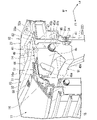
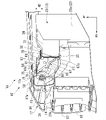
図1、図2に示すように、車両Veは、例えば、エンジンルームの車体前方に設けられる車体前部構造10を備えている。車体前部構造10は、例えば、フロントバルクヘッド12と、基台13と、複数(実施形態では、左右)の第1バンパステイ(バンパステイ)14,14と、複数(実施形態では、左右)の第2バンパステイ(バンパステイ)15,15と、センタアッパビーム16と、フロントバンパフェース(バンパフェース)17と、フロントグリル18と、を備えている。
以下、実施形態では、複数の第1バンパステイとして左右の第1バンパステイ14,14を例示し、複数の第2バンパステイとして左右の第2バンパステイ15,15を例示するが、第1、第2のバンパステイ14,15の個数は任意に選択可能である。
<Vehicle>
As shown in FIGS. 1 and 2, the vehicle Ve includes, for example, a vehicle
In the following embodiment, the left and right first bumper stays 14, 14 are exemplified as the plurality of first bumper stays, and the left and right second bumper stays 15, 15 are exemplified as the plurality of second bumper stays. The numbers of 14 and 15 can be selected arbitrarily.
<フロントバルクヘッド>
図2、図3に示すように、フロントバルクヘッド12は、エンジンルームの車体前方で、かつ、フロントバンパフェース17の車体後方に設けられている。フロントバルクヘッド12は、例えば、左右の縦脚部(一対の縦脚部)22,22と、ロア横メンバ(図示せず)と、アッパ横メンバ(横メンバ)23と、を備えている。
<Front bulkhead>
As shown in FIGS. 2 and 3, the
ロア横メンバは、車体の前下部において車幅方向に延びている。ロア横メンバの左端部から左縦脚部22が立ち上げられ、ロア横メンバの右端部から右縦脚部22が立ち上げられている。左縦脚部22の上端部22aおよび右縦脚部22の上端部22aにアッパ横メンバ23がかけ渡されている。
すなわち、フロントバルクヘッド12は、ロア横メンバ、左右の縦脚部22,22、およびアッパ横メンバ23により平面視矩形枠状に形成されている。フロントバルクヘッド12は、車体骨格の一部を構成する強度、剛性の高い部材である。
The lower lateral member extends in the vehicle width direction at the lower front portion of the vehicle body. A left
That is, the
アッパ横メンバ23は、左縦脚部22の上端部22aおよび右縦脚部22の上端部22aにわたって延在されている。アッパ横メンバ23は、左前方突出部(前方突出部)24および右前方突出部(前方突出部)25を有する。左前方突出部24は、アッパ横メンバ23の中央に対して左寄りの部位から車体前方に向けて突出されている。右前方突出部25は、アッパ横メンバ23の中央に対して右寄りの部位から車体前方に向けて突出されている。
フロントバルクヘッド12の上部(すなわち、アッパ横メンバ23、左縦脚部22の上端部22a、および右縦脚部22の上端部22a)には基台13が支持されている。
The
A
<基台>
基台13は、左右の第1バンパステイ14,14の後部、および左右の第2バンパステイ15,15の後部に配置された状態で設けられている。基台13は、左縦脚部22の上端部22aおよび右縦脚部22の上端部22aにかけ渡されることにより、左縦脚部22の上端部22aおよび右縦脚部22の上端部22aにわたって車幅方向に向けて延在されている。
さらに、基台13は、アッパ横メンバ23の左端部23aおよび右端部23bにもかけ渡されることにより、アッパ横メンバ23の左端部23aおよび右端部23bにわたって車幅方向に向けて延在されている。この状態において、基台13は、アッパ横メンバ23に沿って車幅方向に延びている。
<Base>
The
Further, the
基台13は、基台前面部31と、基台上面部32と、基台下面部33(図7参照)と、左下方接続部(下方接続部)34と、右下方接続部(下方接続部)35と、凹部36と、を有する。
基台前面部31は、アッパ横メンバ23の車体前方において車体前方に向けて配置され、アッパ横メンバ23の左端部23aおよび右端部23bの間で車幅方向に延びている。また、基台前面部31は、左前方突出部24の前端部24a(図9参照)および右前方突出部25の前端部(図示せず)に対向させた状態に配置されている。
The
The base
基台上面部32は、基台前面部31の上辺から車体後方に向けて水平に折り曲げられた状態に設けられている。基台上面部32は、アッパ横メンバ23の上面に沿って配置されている。基台上面部32は、左端部32aおよび右端部32bがアッパ横メンバ23の上面に沿って配置されている。また、基台上面部32は、左端部32aより車幅方向内側の左内側部位32cが左端部32aの下方に配置され、右端部32bより車幅方向内側の右内側部位32dが右端部32bの下方に配置されている。左内側部位32cと右内側部位32dとの間に凹部36が形成されている。
基台下面部33は、基台前面部31の下辺から車体後方に向けて水平に折り曲げられた状態に設けられている。基台下面部33は、アッパ横メンバ23の下面に沿って配置されている。
The base
The base
すなわち、基台13は、基台前面部31、基台上面部32、および基台下面部33により断面コ字状(U字状)に形成されている。なお、コ字状(U字状)は、略コ字状(略U字状)を含む。基台13は、左前方突出部24および右前方突出部25に基台前面部31を車体前方側から対向させた状態において、左右の前方突出部24,25を基台上面部32および基台下面部33で上下方向から挟むように形成されている。
これにより、基台13は、アッパ横メンバ23(すなわち、フロントバルクヘッド12)を補強するアッパースティフナ(上部補強部材)の役割を兼ねている。
That is, the
Thus, the
左下方接続部34は、基台13の左端部から下方に向けて張り出されている。左下方接続部34は、アッパ横メンバ23の左下端部(下端部)より下側において、例えば、左縦脚部22の上端部22aにボルト41などの締結部材により固定(接続)されている。
右下方接続部35は、基台13の右端部から下方に向けて張り出されている。右下方接続部35は、アッパ横メンバ23の右下端部(下端部)より下側において、例えば、右縦脚部22の上端部22aにボルト42により固定(接続)されている。
The lower
The lower
凹部36は、左第2バンパステイ15と右第2バンパステイ15との間で、かつ、車幅方向の中央に形成されている。凹部36は、上部(特に、基台上面部32)が下方に凹むように凹状に形成されている。
ここで、例えば、アッパ横メンバ23のうち、車幅方向の中央部位にフードロック機構(図示せず)が設けられる。このフードロック機構の車体前方に凹部36が配置される。これにより、フードロック機構のロックを解除するロック解除レバー(図示せず)を操作可能な空間を、基台13の凹部36とフードとの上下方向の間に確保できる。
凹部36とフードとの間の空間に手を差し込み、差し込んだ手でロック解除レバーを操作できる。ロック解除レバーを操作することにより、フードロック機構のロックを解除してフードを開けることができる。
The
Here, for example, a hood lock mechanism (not shown) is provided in the central portion of the
A hand can be inserted into the space between the
<第1バンパステイ>
基台13の左端部に左第1バンパステイ(バンパステイ)14が設けられ、基台13の右端部に右第1バンパステイ(バンパステイ)14が設けられている。左第1バンパステイ14および右第1バンパステイ14は、基台13およびフロントバルクヘッド12に支持され、フロントバンパフェース17などを支持(固定)する。
左第1バンパステイ14および右第1バンパステイ14は、概ね左右対称の部材である。よって、左右の第1バンパステイ14に同じ符号を付して、左第1バンパステイ14について詳しく説明し、右第1バンパステイ14の詳しい説明を省略する。また、左第1バンパステイ14を「第1バンパステイ14」と略記して説明する。
<1st Bumper Stay>
A left first bumper stay (bumper stay) 14 is provided on the left end of the
The left
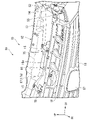
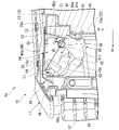
図4から図6に示すように、第1バンパステイ14は、上面部44と、側面部45と、稜線部46と、後下固定部47(図3も参照)と、前面部48と、を有する。上面部44は、前固定部51(図3も参照)と、後上固定部(後方フランジ部)52と、段差部53と、を有する。
前固定部51は、例えば、センタアッパビーム16の上部16aにボルト55およびナット56などの締結部材で固定されている。センタアッパビーム16の上部16aには、例えば、フロントバンパフェース17がクリップ58などの締結部材で固定されている。すなわち、前固定部51は、センタアッパビーム16を介してフロントバンパフェース17に固定されている。
また、前固定部51は、後上固定部52より上下方向において高い位置に配置されている。
As shown in FIGS. 4 to 6, the
The
Further, the
後上固定部52は、前固定部51の車体後方に配置され、基台上面部32のうち左端部32aの上面に沿ってフランジ状に突出されている。後上固定部52は、基台上面部32の左端部32aに上方から重ねられ、例えば、基台上面部32の左端部32aおよびアッパ横メンバ23の左端部23aに接合されることにより設けられている。
The rear
段差部53は、前固定部51から後上固定部52へ向かうに従って下方に傾斜するように延びている。具体的には、段差部53は、前固定部51から車体後方側に向けて下方に傾斜するように延びている。上面部44のうち段差部53の後端部53aおよび後上固定部52の間の部位44aが、例えば、水平に配置されている。
前固定部51は、後上固定部52に対して上下方向においてH1だけ高い位置に配置されている。
The stepped
The
側面部45は、上面部44の外辺から下向きに折り曲げられた状態で下方に延びている。側面部45は、前端部45aから後端部45bまで下辺45cが下り勾配で延びている。よって、側面部45は、車体後方に向かうにつれて高さ方向の幅W1が漸増するように形成されている。側面部45の後端部45bは、基台前面部31やアッパ横メンバ23の近傍に配置されている。
換言すれば、第1バンパステイ14は、前固定部51からアッパ横メンバ23が配置される車体後方に向かうにつれて高さ方向の幅W1が漸増するように形成されている。
The
In other words, the
稜線部46は、上面部44と側面部45とが交差する部位により、第1バンパステイ14の外側に突出するように稜線状に形成されている。稜線部46は、側面部45の前端部45aから後端部45bまで車体後方に向けて延びている。稜線部46のうち、側面部45の後端部45b寄りの部位に凹み部61が形成されている。
凹み部61は、稜線部46のうち、側面部45の後端部45b寄りの部位が第1バンパステイの内側に凹むように凹状に形成されている。
The
The recessed
後下固定部47は、側面部45の後端部45bから車幅方向内側に向けて基台前面部31に沿って折り曲げられることにより形成されている。後下固定部47は、基台前面部31に対向する位置に配置され、後上固定部52の下方に配置されている。後下固定部47は、例えば、基台前面部31に接合されることにより、基台前面部31に設けられている。
The rear lower fixing
前固定部51、後上固定部52、および後下固定部47の下端部47aは、三角形60の各頂点に配置されている。前固定部51、後上固定部52、および後下固定部47の下端部47aを三角形60の各頂点に配置した理由については後で詳しく説明する。
The
前面部48は、側面部45の前端部45aから車幅方向内側に折り曲げられることにより形成されている。前面部48には、例えば、後述するダクト91の前上側部 がクリップ などの締結部材で固定されている。
The
<第2バンパステイ>
図2、図3に示すように、基台13の左前方突出部24に左第2バンパステイ(バンパステイ)15が設けられ、基台13の右前方突出部25に右第2バンパステイ(バンパステイ)15が設けられている。左第2バンパステイ15および右第2バンパステイ15は、基台13およびフロントバルクヘッド12に支持され、フロントバンパフェース17を固定する。
左第2バンパステイ15および右第2バンパステイ15は、概ね左右対称の部材である。よって、左右の第2バンパステイ15に同じ符号を付して、左第2バンパステイ15について詳しく説明し、右第2バンパステイ15の詳しい説明を省略する。また、左第2バンパステイ15を「第2バンパステイ15」と略記して説明する。
<Second Bumper Stay>
As shown in FIGS. 2 and 3 , a left second bumper stay (bumper stay) 15 is provided on the left
The left
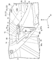
図7から図9に示すように、第2バンパステイ15は、上面部64と、側面部65と、稜線部66と、後下固定部67と、を有する。上面部64は、前固定部71と、後上固定部(後方フランジ部)72と、段差部73と、を有する。
前固定部71は、例えば、後述するセンタアッパビーム16の上部16aにボルト75およびナット76などの締結部材で固定されている。センタアッパビーム16の上部16aには、例えば、後述するフロントバンパフェース17がクリップ58などの締結部材で固定されている。すなわち、前固定部71は、センタアッパビーム16を介してフロントバンパフェース17に設けられている。
また、前固定部71は、後上固定部72より上下方向において高い位置に配置されている。
As shown in FIGS. 7 to 9 , the
The
Further, the
後上固定部72は、前固定部71の車体後方に配置され、基台上面部32のうち左内側部位32cの上面に沿ってフランジ状に突出されている。後上固定部72は、基台上面部32の左内側部位32cに上方から重ねられ、例えば、アッパ横メンバ23の左前方突出部24にボルト78により固定されることにより設けられている。すなわち、後上固定部72は、基台上面部32の左内側部位32cおよびアッパ横メンバ23の左前方突出部24にボルト78により固定されることにより設けられている。
ここで、基台上面部32の左内側部位32cは、基台上面部32の左端部32a(図3参照)に対して低い位置に配置されている。よって、第2バンパステイ15の後上固定部72は、第1バンパステイ14の後上固定部52に対して低い位置に配置されている。
The rear
Here, the left
段差部73は、前固定部71から後上固定部72へ向かうに従って下方に傾斜するように延びている。具体的には、段差部73は、前固定部71から後上固定部72まで車体後方に向かうに従って下方に傾斜するように延びている。
前固定部71は、後上固定部72に対して上下方向においてH2だけ高い位置に配置されている。
The stepped
The
ここで、第2バンパステイ15の高さH2は、第1バンパステイ14の高さH1(図6参照)より大きく設定されている。第2バンパステイ15の高さH2を第1バンパステイ14の高さH1より大きく設定した理由は以下の通りである。
すなわち、図3、図6、図9に示すように、例えば、複数のバンパステイ(具体的には、第1バンパステイ14および第2バンパステイ15)が車幅方向に間隔をあけて基台13に設けられている。また、第1バンパステイ14の後上固定部52は、第2バンパステイ15の後上固定部52に対して低い位置に配置されている。
Here, the height H2 of the
That is, as shown in FIGS. 3, 6, and 9, for example, a plurality of bumper stays (specifically, a
そこで、第2バンパステイ15の高さH2を第1バンパステイ14の高さH1より大きく設定した。よって、第1バンパステイ14の前固定部51および第2バンパステイ15の前固定部71を同じ高さに配置できる。すなわち、基台13に設けた第1バンパステイ14の前固定部51および第2バンパステイ15の前固定部71(すなわち、複数のバンパステイの各前固定部)を、車幅方向において水平に配置できる。
第1バンパステイ14の前固定部51および第2バンパステイ15の前固定部71には、センタアッパビーム16の上部16aを介してフロントバンパフェース17の上フランジ17aが固定されている。これにより、フロントバンパフェース17を第1バンパステイ14および第2バンパステイ15に精度よく固定できる。
Therefore, the height H2 of the
The
図7から図9に戻って、側面部65は、上面部64の外辺から下向きに折り曲げられた状態で下方に延びている。側面部65は、前端部65aから後端部65bまで下辺65cが下り勾配で延びることにより、車体後方に向かうにつれて高さ方向の幅W2が漸増するように形成されている。側面部65の後端部65bは、基台前面部31やアッパ横メンバ23(具体的には、左前方突出部24)の近傍に配置されている。
換言すれば、第2バンパステイ15は、前固定部71からアッパ横メンバ23の左前方突出部24が配置される車体後方に向かうにつれて高さ方向の幅W2が漸増するように形成されている。
Returning to FIG. 7 to FIG. 9, the
In other words, the
稜線部66は、上面部64と側面部65とが交差する部位により、第2バンパステイ15の外側に突出するように稜線状に形成されている。稜線部66は、側面部65の前端部65aから後端部65bまで車体後方に向けて延びている。稜線部66のうち、側面部65の後端部65b寄りの部位に凹み部81が形成されている。
凹み部81は、稜線部66のうち、側面部65の後端部65b寄りの部位が第2バンパステイ15の内側に凹むように凹状に形成されている。
The
The recessed
後下固定部67は、側面部65の後端部65bから車幅方向外側に向けて基台前面部31に沿って折り曲げられることにより形成されている。後下固定部67は、基台前面部31に対向する位置に配置されることにより、後上固定部72の下方に配置されている。後下固定部67は、例えば、基台前面部31に接合されることにより、基台前面部31に設けられている。
The rear lower fixing
前固定部71、後上固定部72、および後下固定部67の下端部67aは、三角形80の各頂点に配置されている。前固定部71、後上固定部72、および後下固定部67の下端部67aを三角形80の各頂点に配置した理由については後で詳しく説明する。
The
<センタアッパビーム>
図2、図6、図9に示すように、第1バンパステイ14の前固定部51および第2バンパステイ15の前固定部71にセンタアッパビーム16が固定されている。具体的には、センタアッパビーム16は、第1バンパステイ14および第2バンパステイ15の車体前方側で、かつ、基台13と対向する位置に車幅方向へ向けて配置されている。センタアッパビーム16は、上部16aが第1バンパステイ14の前固定部51および第2バンパステイ15の前固定部71に載置可能に車幅方向に平坦に延びている。
<Center upper beam>
As shown in FIGS. 2 , 6 and 9 , the center
センタアッパビーム16の上部16aは、第1バンパステイ14の前固定部51に載置された状態において、例えば、前固定部51にボルト55およびナット56で固定されている。また、センタアッパビーム16の上部16aは、第2バンパステイ15の前固定部71に載置された状態において、例えば、前固定部71にボルト75およびナット76で固定されている。すなわち、第1バンパステイ14の前固定部51および第2バンパステイ15の前固定部71にセンタアッパビーム16の上部16aが固定されている。
The
センタアッパビーム16の上部16aには、例えば、後述するフロントバンパフェース17の上フランジ17aがクリップ58などの締結部材で強固に固定されている。すなわち、第1バンパステイ14の前固定部51および第2バンパステイ15の前固定部71には、センタアッパビーム16を介してフロントバンパフェース17が支持されている。
ここで、センタアッパビーム16の上部16aは、第1バンパステイ14の前固定部51および第2バンパステイ15の前固定部71に載置可能に車幅方向に平坦に延びている。これにより、フロントバンパフェース17の上フランジ17aを車幅方向において水平に延ばすことができ、上フランジ17a(すなわち、フロントバンパフェース17)の形状を簡素化できる。
For example, an
Here, the
<フロントバンパフェース、フロントグリル>
図1、図2に示すように、フロントバンパフェース17は、車両Veの前部(すなわち、車体の前部)に設けられてフロントバンパ(図示せず)を車体前方側から覆い、かつ、車両Veの前面を装飾する部材である。フロントバンパフェース17の車幅方向中央にはフロントグリル18が設けられている。
フロントグリル18は、フロントバンパフェース17の車体後方に配置されたシャッタグリル101(後述する)に走行風(外気)を導入可能に開口されている。フロントグリル18の中央にはエンブレム87が設けられている。
<Front bumper face, front grille>
As shown in FIGS. 1 and 2, the
The
<ダクト>
図5、図6、図10に示すように、フロントバルクヘッド12および基台13の車体前方にダクト91が設けられている。ダクト91は、例えば、フロントバルクヘッド12に取り付けられたラジエータやコンデンサ(図示せず)に走行風(外気、空気)を案内する。ダクト91は、センタアッパビーム16、基台13、および第1バンパステイ14に固定(接続)されている。
<Duct>
As shown in FIGS. 5, 6 and 10, a
具体的には、ダクト91は、例えば、前上部91aがセンタアッパビーム16の前壁部16bにクリップ93などの締結部材で固定されている。また、ダクト91は、例えば、後上フランジ部91bが基台13の基台前面部31にクリップ94などの締結部材で固定されている。さらに、ダクト91は、例えば、後上側部91cが第1バンパステイ14のうち側面部45の後下部45dにクリップ95などの締結部材で固定されている。加えて、ダクト91は、例えば、前上側部91dが第1バンパステイ14の前面部48にクリップ96などの締結部材で固定されている。
Specifically, the
よって、センタアッパビーム16、基台13、および第1バンパステイ14にダクト91を強固に支持できる。これにより、ダクト91を樹脂で形成した場合でも、例えば、車両Veの走行中に振動の影響を受け難くでき、ダクト91による走行風(空気)の通り道に影響を与え難くできる。すなわち、ダクト91は、フロントバルクヘッド12に取り付けられたラジエータやコンデンサに走行風を良好に案内できる。
Therefore, the
<車載部品>
図10に示すように、第1バンパステイ14および第2バンパステイ15より下方にシャッタグリル(車載部品)101が配置されている。シャッタグリル101は、フロントグリル18の車体後方で、かつ、ダクト91の前開口部91eに設けられ、フロントグリル18から導入された走行風をダクト91に案内する。すなわち、シャッタグリル101は、例えば、シャッタ102(図7参照)を開閉することによりダクト91に案内する走行風を調整して、ラジエータやコンデンサに導く走行風を制御する。
<Automotive parts>
As shown in FIG. 10 , a shutter grill (vehicle component) 101 is arranged below the
ここで、フロントバルクヘッド12の上部(例えば、アッパ横メンバ23および左右の縦脚部22,22の上端部22a,22a)に基台13が支持され、基台13に第1バンパステイ14および第2バンパステイ15が支持されている。よって、フロントバンパフェース17とフロントバルクヘッド12との間の空間のうち上方に、第1バンパステイ14および第2バンパステイ15を配置できる。これにより、第1バンパステイ14および第2バンパステイ15より下方にシャッタグリル101などの車載部品を搭載する搭載空間104を確保できる。したがって、第1バンパステイ14および第2バンパステイ15より下方の搭載空間104にシャッタグリル101を搭載できる。
さらに、例えば、前面軽衝突により車体前部に衝突荷重F1が入力した際に、シャッタグリル101が車体後方に後退できる空間(すなわち、搭載空間104)を第1バンパステイ14および第2バンパステイ15の下方に確保できる。
Here, the
Further, for example, when a collision load F1 is input to the front portion of the vehicle body due to a frontal light collision, a space (that is, a mounting space 104) in which the
また、シャッタグリル101の車体前方において、第1バンパステイ14および第2バンパステイ15より下方にレーダ装置(車載部品)108が配置されている。具体的には、レーダ装置108は、例えば、エンブレム87の車体後方に設けられている。レーダ装置108は、例えば、障害物を検知して車両Veのブレーキを制御し、あるいは、周辺車両の速度や車間距離を測定して車両Veの速度や車間距離を制御する。
A radar device (vehicle component) 108 is arranged below the
また、前述したように、第1バンパステイ14および第2バンパステイ15の下方には、車載部品を搭載する搭載空間104が確保されている。これにより、第1バンパステイ14および第2バンパステイ15より下方の搭載空間104にレーダ装置108を搭載できる。
さらに、例えば、前面軽衝突により車体前部に衝突荷重F1が入力した際に、レーダ装置108が車体後方に後退できる空間(すなわち、搭載空間104)を第1バンパステイ14および第2バンパステイ15の下方に確保できる。
Further, as described above, the mounting
Furthermore, for example, when a collision load F1 is input to the front portion of the vehicle body due to a frontal light collision, a space (that is, the mounting space 104) in which the
以上説明したように、実施形態の車体前部構造10によれば、図3から図5に示すように、第1バンパステイ14は、前固定部51、後上固定部52、および後下固定部47の下端部47aが、三角形60の各頂点に配置されている。また、前固定部51には、センタアッパビーム16を介してフロントバンパフェース17が設けられている。
よって、前固定部51にフロントバンパフェース17の重量(荷重)F2が下向きに作用する。前固定部51に作用する荷重F2は、後上固定部52に作用する引張荷重F3と、後下固定部47(特に、下端部47a)に作用する圧縮荷重F4と、に分散(変換)される。
As described above, according to the vehicle
Therefore, the weight (load) F<b>2 of the front bumper face 17 acts downward on the
後下固定部47は、基台前面部31(すなわち、基台13)に設けられている。また、基台13は、フロントバルクヘッド12に支持されている。フロントバルクヘッド12は、車体骨格の一部を構成する強度、剛性の高い部材である。よって、後下固定部47に作用する圧縮荷重F4を基台13(すなわち、フロントバルクヘッド12)で確実に支えることができる。
一方、後上固定部52は、基台上面部32(すなわち、基台13)に設けられている。よって、後上固定部52に作用する引張荷重F3を基台13(すなわち、フロントバルクヘッド12)で支えることができる。
The rear lower fixing
On the other hand, the rear
また、図3、図9に示すように、第2バンパステイ15は、前固定部71、後上固定部72、および後下固定部67の下端部67aが、三角形80の各頂点に配置されている。また、前固定部71には、センタアッパビーム16を介してフロントバンパフェース17が設けられている。
よって、前固定部71にフロントバンパフェース17の重量(荷重)F5が下向きに作用する。前固定部71に作用する荷重F5は、後上固定部72に作用する引張荷重F6と、後下固定部67(特に、下端部67a)に作用する圧縮荷重F7と、に分散(変換)される。
3 and 9, the
Therefore, the weight (load) F5 of the front bumper face 17 acts downward on the
後下固定部67は、基台前面部31(すなわち、基台13)に設けられている。また、基台13は、フロントバルクヘッド12の左前方突出部24に支持されている。フロントバルクヘッド12は、車体骨格の一部を構成する強度、剛性の高い部材である。よって、後下固定部67に作用する圧縮荷重F7を基台13(すなわち、フロントバルクヘッド12)で確実に支えることができる。
一方、後上固定部72は、基台上面部32(すなわち、基台13)に設けられている。よって、後上固定部52に作用する引張荷重F6を基台13(すなわち、フロントバルクヘッド12)で支えることができる。
The rear lower fixing
On the other hand, the rear
これにより、図5、図9に示すように、フロントバンパフェース17の重量(荷重)F2,F5を第1バンパステイ14および第2バンパステイ15で支持できる。これにより、フロントバンパフェース17の垂れ下がりを第1バンパステイ14および第2バンパステイ15で抑制できる。
As a result, the weights (loads) F2 and F5 of the
また、図5に示すように、第1バンパステイ14は、前固定部51からアッパ横メンバ23が配置された車体後方に向かうにつれて側面部45の高さ方向の幅W1が漸増するように形成されている。よって、前固定部51および後下固定部47の下端部47aを連結する側面部45の下辺45cを、車体後方へ向けて下り勾配に延ばすことができる。
これにより、フロントバンパフェース17の荷重F2が前固定部51に作用した状態において、前固定部51に作用した荷重F2の一部を、後下固定部47(特に、下端部47a)が基台前面部31を押す方向に作用する圧縮荷重F4に分散(変換)しやすくできる。すなわち、圧縮荷重F4をフロントバルクヘッド12に伝えて支持しやすくできる。
Further, as shown in FIG. 5, the
As a result, when the load F2 of the front bumper face 17 acts on the
さらに、図8、図9に示すように、第2バンパステイ15は、前固定部71からアッパ横メンバ23が配置された車体後方に向かうにつれて側面部65の高さ方向の幅W2が漸増するように形成されている。よって、前固定部71および後下固定部67の下端部67aを連結する側面部65の下辺65cを、車体後方へ向けて下り勾配に延ばすことができる。
これにより、フロントバンパフェース17の荷重F5が前固定部71に作用した状態において、前固定部71に作用した荷重F5の一部を、後下固定部67(特に、下端部67a)が基台前面部31を押す方向に作用する圧縮荷重F7に分散(変換)しやすくできる。すなわち、圧縮荷重F7をフロントバルクヘッド12に伝えて支持しやすくできる。
Further, as shown in FIGS. 8 and 9, the
As a result, when the load F5 of the front bumper face 17 acts on the
このように、図5、図9に示すように、圧縮荷重F4をフロントバルクヘッド12に伝えて支持しやすくでき、さらに、圧縮荷重F7をフロントバルクヘッド12に伝えて支持しやすくできる。これにより、フロントバンパフェース17の垂れ下がりを第1バンパステイ14および第2バンパステイ15で一層良好に抑制できる。
In this manner, as shown in FIGS. 5 and 9, the compressive load F4 can be transmitted to the
また、図3、図4に示すように、第1バンパステイ14は、上面部44と側面部45とが交差する部位に稜線部46を形成した。さらに、稜線部46に凹み部61を形成した。よって、第1バンパステイ14そのものの強度を凹み部61で向上させ、かつ、例えば、上面部44が稜線部46を境にして側面部45へ向けて変形することを抑制できる。
さらに、図3、図8に示すように、第2バンパステイ15は、上面部64と側面部65とが交差する部位に稜線部66を形成した。さらに、稜線部66に凹み部81を形成した。よって、第2バンパステイ15そのものの強度を凹み部81で向上させ、かつ、例えば、上面部64が稜線部66を境にして側面部65へ向けて変形することを抑制できる。
Further, as shown in FIGS. 3 and 4, the
Further, as shown in FIGS. 3 and 8 , the
これにより、図5、図9に示すように、フロントバンパフェース17から第1バンパステイ14の前固定部51に作用する荷重F2に対して、第1バンパステイ14で強く踏ん張ることができる。また、フロントバンパフェース17から第2バンパステイ15の前固定部71に作用する荷重F5に対して、第2バンパステイ15で強く踏ん張ることができる。
したがって、第1バンパステイ14の前固定部51および第2バンパステイ15の前固定部71に作用した荷重F2,F5を第1バンパステイ14および第2バンパステイ15で支持できる。
As a result, as shown in FIGS. 5 and 9, the load F2 acting from the
Therefore, the
また、図3、図4に示すように、第1バンパステイ14は、上面部44に、前固定部51、後上固定部52、および段差部53を有する。後上固定部52は、基台上面部32やフロントバルクヘッド12のアッパ横メンバ23に重ねられるように設けられている。さらに、段差部53は、前固定部51から後上固定部52へ向かうに従って下方に傾斜するように延びている。よって、上面部44の剛性(特に、面剛性)を向上させることにより、第1バンパステイ14の剛性を向上させることができる。
Further, as shown in FIGS. 3 and 4 , the
さらに、図8、図9に示すように、第2バンパステイ15は、上面部64に、前固定部71、後上固定部72、および段差部73を有する。後上固定部72は、基台上面部32やフロントバルクヘッド12のアッパ横メンバ23に重ねられるように設けられている。さらに、段差部73は、前固定部71から後上固定部72へ向かうに従って下方に傾斜するように延びている。よって、上面部64の剛性(特に、面剛性)を向上させることにより、第2バンパステイ15の剛性を向上させることができる。
Further, as shown in FIGS. 8 and 9 , the
これにより、図5、図9に示すように、フロントバンパフェース17から第1バンパステイ14の前固定部51に作用する荷重F2を、第1バンパステイ14を経て基台13の側に伝達させやすくできる。また、フロントバンパフェース17から第2バンパステイ15の前固定部71に作用する荷重F5を、第2バンパステイ15を経て基台13の側に伝達させやすくできる。
したがって、フロントバンパフェース17の垂れ下がりを第1バンパステイ14および第2バンパステイ15で一層良好に抑止できる。
As a result, as shown in FIGS. 5 and 9, the load F2 acting from the
Therefore, the
また、図3、図7、図9に示すように、基台13をコ字状に形成することにより、フロントバルクヘッド12のアッパ横メンバ23(特に、左前方突出部24、右前方突出部25など)を、基台13で上下方向から挟むことができる。よって、基台13の剛性を高めることができ、基台13でアッパースティフナ(すなわち、補強部材)としての役割を果たすことができる。
さらに、基台13をフロントバルクヘッド12の左右の縦脚部22にかけ渡した。よって、基台13をフロントバルクヘッド12の車体前方側に配置した状態において、フロントバルクヘッド12に強固に支持できる。この基台13に第1バンパステイ14および第2バンパステイ15が取り付けられている。これにより、第1バンパステイ14および第2バンパステイ15を基台13から車体前方に向けて配置した状態において、基台13に強固に固定できる。
Further, as shown in FIGS. 3, 7, and 9, by forming the base 13 in a U-shape, the
Further, the
ここで、例えば、フロントバンパフェース17がフロントバルクヘッド12に対して車体前方の側に比較的大きく離れて配置することが考えられる。この場合においても、フロントバルクヘッド12の車体前方に基台13を配置することにより、第1バンパステイ14および第2バンパステイ15の車体前後方向の長さを抑えることができる。これにより、フロントバンパフェース17を第1バンパステイ14および第2バンパステイ15で強固に支持できる。
Here, for example, it is conceivable that the
また、アッパ横メンバ23の左前方突出部24および右前方突出部25を、基台13で上下方向から挟み、さらに、フロントバルクヘッド12の左右の縦脚部22に基台13をかけ渡した。よって、フロントバルクヘッド12を基台13で補強することができる。
ここで、車両Veの走行中に、例えば、片側の車輪だけ段差に乗り上げることにより、フロントバルクヘッド12に捩れ方向の荷重が入力することが考えられる。この場合において、フロントバルクヘッド12に捩れ方向の荷重に対する剛性を、基台13(すなわち、アッパースティフナ)により高めることができる。
The left
Here, while the vehicle Ve is running, for example, it is conceivable that a torsional load is input to the
また、図3に示すように、アッパ横メンバ23の左前方突出部24および右前方突出部25を基台13で挟むように配置した。さらに、基台13の左下方接続部34および右下方接続部35を、アッパ横メンバ23の下端部より下側において左右の縦脚部22,22の上端部22a,22aに固定させた。これにより、基台13は、例えば、左右の縦脚部22を車幅方向外側にくの字状(V字状)に折り曲げる荷重に対しても、フロントバルクヘッド12の剛性を高めることができる。
すなわち、例えば、フロントバルクヘッド12に左右の縦脚部22を車幅方向外側にくの字状(V字状)に折り曲げる荷重が入力した際に、左右の縦脚部22が車幅方向外側にくの字状(V字状)に折れ曲がることを基台13で抑制できる。
Further, as shown in FIG. 3 , the left
That is, for example, when a load for bending the left and right
なお、本発明の技術的範囲は前記実施形態に限定されるものではなく、本発明の趣旨を逸脱しない範囲において種々の変更を加えることが可能である。 The technical scope of the present invention is not limited to the above-described embodiments, and various modifications can be made without departing from the scope of the present invention.
その他、本発明の趣旨に逸脱しない範囲で、前記実施形態における構成要素を周知の構成要素に置き換えることは適宜可能であり、また、前記した変形例を適宜組み合わせてもよい。 In addition, it is possible to appropriately replace the constituent elements in the above-described embodiment with well-known constituent elements without departing from the spirit of the present invention, and the modifications described above may be combined as appropriate.
Ve 車両
10 車体前部構造
12 フロントバルクヘッド
13 基台
14 第1バンパステイ(バンパステイ、左右の第1バンパステイ)
15 第2バンパステイ(バンパステイ、左右の第2バンパステイ)
16 センタアッパビーム
17 フロントバンパフェース(バンパフェース)
17a 上フランジ
22 左右の縦脚部(一対の縦脚部)
23 アッパ横メンバ(横メンバ)
24 左前方突出部(前方突出部)
25 右前方突出部(前方突出部)
31 基台前面部
32 基台上面部
34 左下方接続部(下方接続部)
35 右下方接続部(下方接続部)
36 凹部
44,64 上面部
45,65 側面部
46,66 稜線部
47,67 後下固定部
51,71 前固定部
52,72 後上固定部
53,73 段差部
60,80 三角形
61,81 凹み部
91 ダクト
101 シャッタグリル
108 レーダ装置
W1,W2 高さ方向の幅
15 2nd bumper stay (bumpa stay, left and right 2nd bumper stay)
16 center
23 Upper lateral member (lateral member)
24 Left forward protrusion (forward protrusion)
25 right forward protrusion (forward protrusion)
31 base
35 lower right connection (lower connection)
36 recessed
Claims (10)
前記フロントバルクヘッドの上部に支持され、車体前方に向けて配置された基台前面部と、前記基台前面部の上端に設けられた基台上面部とを有する基台と、
前記基台および前記フロントバルクヘッドに支持され、前記バンパフェースを固定するバンパステイと、を備え、
前記バンパステイは、
前記バンパフェースを固定する前固定部と、
前記前固定部の車体後方に配置され、前記基台上面部に設けられた後上固定部と、
前記後上固定部の下方に配置され、前記基台前面部に設けられた後下固定部と、を有し、
前記前固定部、前記後上固定部、および前記後下固定部は、三角形の各頂点に配置されている、
ことを特徴とする車体前部構造。 A vehicle body front structure in which a bumper face is provided in the front part of a vehicle body and a front bulkhead is provided behind the bumper face,
a base having a base front face portion supported on the upper portion of the front bulkhead and arranged toward the front of the vehicle body, and a base top face portion provided at the upper end of the base front face portion;
a bumper stay supported by the base and the front bulkhead and fixing the bumper face;
The bumper stay is
a front fixing portion for fixing the bumper face;
a rear upper fixing portion arranged behind the front fixing portion of the vehicle body and provided on the upper surface portion of the base;
a rear lower fixing portion disposed below the rear upper fixing portion and provided on the base front surface,
The front fixing portion, the rear upper fixing portion, and the rear lower fixing portion are arranged at vertices of a triangle,
A vehicle body front structure characterized by:
前記前固定部から前記フロントバルクヘッドが配置される車体後方に向かうにつれて高さ方向の幅が漸増する、
ことを特徴とする請求項1に記載の車体前部構造。 The bumper stay is
The width in the height direction gradually increases from the front fixing portion toward the rear of the vehicle body where the front bulkhead is arranged.
The vehicle body front structure according to claim 1, characterized in that:
前記前固定部を有する上面部と、
前記上面部から下方に延びる側面部と、
前記上面部と前記側面部とが交差する部位により形成される稜線部と、を有し、
前記稜線部は凹み部を有する、
ことを特徴とする請求項1に記載の車体前部構造。 The bumper stay is
an upper surface portion having the front fixing portion;
a side portion extending downward from the top portion;
a ridgeline portion formed by a portion where the top surface portion and the side surface portion intersect,
The ridge has a recess,
The vehicle body front structure according to claim 1, characterized in that:
前記バンパステイの上面部は、
前記前固定部および前記後上固定部に加えて、
前記前固定部から前記後上固定部へ向かうに従って下方に傾斜する段差部を有する、
ことを特徴とする請求項1に記載の車体前部構造。 The rear upper fixing part is arranged so as to be superimposed on the base upper surface part,
The upper surface portion of the bumper stay is
In addition to the front fixing portion and the rear upper fixing portion,
Having a stepped portion that slopes downward from the front fixing portion toward the rear upper fixing portion,
The vehicle body front structure according to claim 1, characterized in that:
前記バンパステイの後部に配置され、前記フロントバルクヘッドの前方突出部に前記基台前面部を対向させた状態において前記前方突出部を上下方向から挟むようにコ字状に形成されたアッパースティフナであって、
前記フロントバルクヘッドの一対の縦脚部にわたって延在されている、
ことを特徴とする請求項1に記載の車体前部構造。 The base is
An upper stiffener disposed at the rear portion of the bumper stay and formed in a U-shape so as to sandwich the forward projecting portion from above and below in a state in which the front surface portion of the base is opposed to the forward projecting portion of the front bulkhead. hand,
extending across a pair of longitudinal legs of the front bulkhead;
The vehicle body front structure according to claim 1, characterized in that:
前記一対の縦脚部に加えて、前記一対の縦脚部にわたって延在され、前記前方突出部を有する横メンバを備え、
前記基台は、
前記横メンバより下側において、前記一対の縦脚部に固定される下方接続部を有する、
ことを特徴とする請求項5に記載の車体前部構造。 The front bulkhead is
In addition to the pair of vertical legs, a horizontal member extending over the pair of vertical legs and having the forward protrusion,
The base is
A lower connecting portion fixed to the pair of vertical legs below the horizontal member,
The vehicle body front structure according to claim 5, characterized in that:
前記ダクトは、
前記基台および前記バンパステイと固定されている、
ことを特徴とする請求項5に記載の車体前部構造。 A duct provided in front of the front bulkhead of the vehicle body for guiding outside air to the front bulkhead side,
The duct is
fixed with the base and the bumper stay;
The vehicle body front structure according to claim 5, characterized in that:
前記センタアッパビームは、
前記バンパステイの前記前固定部に固定されている、
ことを特徴とする請求項1に記載の車体前部構造。 comprising a center upper beam that supports the upper flange of the bumper face;
The center upper beam is
fixed to the front fixing portion of the bumper stay;
The vehicle body front structure according to claim 1, characterized in that:
車幅方向の中央において下方に凹むように形成された凹部を有する、
ことを特徴とする請求項1に記載の車体前部構造。 The base is
Having a recess formed so as to be recessed downward at the center in the vehicle width direction,
The vehicle body front structure according to claim 1, characterized in that:
前記後上固定部より上下方向において高い位置に配置されている、
ことを特徴とする請求項9に記載の車体前部構造。 The front fixing portion of the bumper stay,
arranged at a position higher in the vertical direction than the rear upper fixing part,
The vehicle body front structure according to claim 9, characterized in that:
Priority Applications (2)
| Application Number | Priority Date | Filing Date | Title |
|---|---|---|---|
| JP2021042630A JP7192010B2 (en) | 2021-03-16 | 2021-03-16 | Body front structure |
| CN202210116748.2A CN115071837B (en) | 2021-03-16 | 2022-02-07 | Front structure of vehicle body |
Applications Claiming Priority (1)
| Application Number | Priority Date | Filing Date | Title |
|---|---|---|---|
| JP2021042630A JP7192010B2 (en) | 2021-03-16 | 2021-03-16 | Body front structure |
Publications (2)
| Publication Number | Publication Date |
|---|---|
| JP2022142454A JP2022142454A (en) | 2022-09-30 |
| JP7192010B2 true JP7192010B2 (en) | 2022-12-19 |
Family
ID=83245671
Family Applications (1)
| Application Number | Title | Priority Date | Filing Date |
|---|---|---|---|
| JP2021042630A Active JP7192010B2 (en) | 2021-03-16 | 2021-03-16 | Body front structure |
Country Status (2)
| Country | Link |
|---|---|
| JP (1) | JP7192010B2 (en) |
| CN (1) | CN115071837B (en) |
Citations (6)
| Publication number | Priority date | Publication date | Assignee | Title |
|---|---|---|---|---|
| JP2010023792A (en) | 2008-07-24 | 2010-02-04 | Honda Motor Co Ltd | Vehicle body front part structure |
| JP2011073661A (en) | 2009-10-02 | 2011-04-14 | Honda Motor Co Ltd | Front grille bracket for vehicle |
| JP2011084172A (en) | 2009-10-15 | 2011-04-28 | Honda Motor Co Ltd | Vehicle body front structure |
| JP2012091655A (en) | 2010-10-26 | 2012-05-17 | Honda Motor Co Ltd | Bumper face mounting structure for vehicle |
| JP5396100B2 (en) | 2009-02-20 | 2014-01-22 | 本田技研工業株式会社 | Body front structure |
| JP6304202B2 (en) | 2015-11-09 | 2018-04-04 | マツダ株式会社 | Vehicle front structure |
Family Cites Families (5)
| Publication number | Priority date | Publication date | Assignee | Title |
|---|---|---|---|---|
| JP3464598B2 (en) * | 1997-09-09 | 2003-11-10 | 日産車体株式会社 | Frame front end structure |
| JP5195657B2 (en) * | 2009-06-12 | 2013-05-08 | トヨタ自動車株式会社 | Bumper cover support structure |
| JP5373004B2 (en) * | 2011-07-20 | 2013-12-18 | 本田技研工業株式会社 | Auto body front structure |
| KR101394055B1 (en) * | 2013-05-30 | 2014-05-09 | 현대자동차 주식회사 | Bumper cover fixing bracket of automobile |
| CN207697684U (en) * | 2017-10-27 | 2018-08-07 | 华晨汽车集团控股有限公司 | A kind of automobile front beam mounting bracket |
-
2021
- 2021-03-16 JP JP2021042630A patent/JP7192010B2/en active Active
-
2022
- 2022-02-07 CN CN202210116748.2A patent/CN115071837B/en active Active
Patent Citations (6)
| Publication number | Priority date | Publication date | Assignee | Title |
|---|---|---|---|---|
| JP2010023792A (en) | 2008-07-24 | 2010-02-04 | Honda Motor Co Ltd | Vehicle body front part structure |
| JP5396100B2 (en) | 2009-02-20 | 2014-01-22 | 本田技研工業株式会社 | Body front structure |
| JP2011073661A (en) | 2009-10-02 | 2011-04-14 | Honda Motor Co Ltd | Front grille bracket for vehicle |
| JP2011084172A (en) | 2009-10-15 | 2011-04-28 | Honda Motor Co Ltd | Vehicle body front structure |
| JP2012091655A (en) | 2010-10-26 | 2012-05-17 | Honda Motor Co Ltd | Bumper face mounting structure for vehicle |
| JP6304202B2 (en) | 2015-11-09 | 2018-04-04 | マツダ株式会社 | Vehicle front structure |
Also Published As
| Publication number | Publication date |
|---|---|
| JP2022142454A (en) | 2022-09-30 |
| CN115071837B (en) | 2024-02-06 |
| CN115071837A (en) | 2022-09-20 |
Similar Documents
| Publication | Publication Date | Title |
|---|---|---|
| JP5034639B2 (en) | Automotive front structure | |
| JP6235628B2 (en) | Auto body structure | |
| JP6460135B2 (en) | Vehicle side body structure | |
| JP2563632Y2 (en) | Car front body structure | |
| US6916063B2 (en) | Reinforced structure for rear part of front side rail in vehicle | |
| CN111776077B (en) | Front pillar structure for vehicle | |
| JP2009287950A (en) | Mounting structure of radar device | |
| JP6568572B2 (en) | Bumper device for vehicle | |
| CN111746445B (en) | Body structure | |
| JP2006193086A (en) | Dash panel reinforcement structure | |
| JPH0930452A (en) | Side sill reinforcement structure for automobiles | |
| JP2010000866A (en) | Front body structure of vehicle | |
| JP2010000866A5 (en) | ||
| EP3808606B1 (en) | Vehicle front structure, and vehicle | |
| JP7192010B2 (en) | Body front structure | |
| JP6221164B2 (en) | Body structure | |
| JP2006088886A (en) | Body frame structure | |
| CN115892240B (en) | Rear structure of the vehicle body | |
| US12528541B2 (en) | Side structure of vehicle body | |
| JP2014151868A (en) | Vehicle front part structure | |
| KR20090064668A (en) | Reinforcement Structure of Front End Module | |
| JP2021142764A (en) | Body structure of automobile | |
| JP2009126381A (en) | Auto body front structure | |
| JP6387567B2 (en) | Lower body structure | |
| JP6197932B1 (en) | Bumper reinforcement structure |
Legal Events
| Date | Code | Title | Description |
|---|---|---|---|
| A621 | Written request for application examination |
Free format text: JAPANESE INTERMEDIATE CODE: A621 Effective date: 20211129 |
|
| TRDD | Decision of grant or rejection written | ||
| A01 | Written decision to grant a patent or to grant a registration (utility model) |
Free format text: JAPANESE INTERMEDIATE CODE: A01 Effective date: 20221129 |
|
| A61 | First payment of annual fees (during grant procedure) |
Free format text: JAPANESE INTERMEDIATE CODE: A61 Effective date: 20221207 |
|
| R150 | Certificate of patent or registration of utility model |
Ref document number: 7192010 Country of ref document: JP Free format text: JAPANESE INTERMEDIATE CODE: R150 |