JP7192302B2 - フレーム構造及び画像形成装置 - Google Patents
フレーム構造及び画像形成装置 Download PDFInfo
- Publication number
- JP7192302B2 JP7192302B2 JP2018152599A JP2018152599A JP7192302B2 JP 7192302 B2 JP7192302 B2 JP 7192302B2 JP 2018152599 A JP2018152599 A JP 2018152599A JP 2018152599 A JP2018152599 A JP 2018152599A JP 7192302 B2 JP7192302 B2 JP 7192302B2
- Authority
- JP
- Japan
- Prior art keywords
- frame
- frame means
- pair
- edges
- frame structure
- Prior art date
- Legal status (The legal status is an assumption and is not a legal conclusion. Google has not performed a legal analysis and makes no representation as to the accuracy of the status listed.)
- Active
Links
- 238000005452 bending Methods 0.000 claims description 17
- 229910000831 Steel Inorganic materials 0.000 claims description 16
- 239000010959 steel Substances 0.000 claims description 16
- 229910001209 Low-carbon steel Inorganic materials 0.000 claims description 14
- 229910052751 metal Inorganic materials 0.000 claims description 5
- 239000002184 metal Substances 0.000 claims description 5
- 238000009864 tensile test Methods 0.000 claims description 4
- 238000012546 transfer Methods 0.000 description 71
- 229910052799 carbon Inorganic materials 0.000 description 21
- 238000010586 diagram Methods 0.000 description 14
- 238000004140 cleaning Methods 0.000 description 11
- 239000000463 material Substances 0.000 description 11
- 238000010438 heat treatment Methods 0.000 description 8
- 230000002093 peripheral effect Effects 0.000 description 7
- 238000005520 cutting process Methods 0.000 description 6
- 238000012545 processing Methods 0.000 description 6
- 238000000034 method Methods 0.000 description 5
- 238000003825 pressing Methods 0.000 description 5
- 239000003086 colorant Substances 0.000 description 3
- 238000011161 development Methods 0.000 description 3
- 238000003384 imaging method Methods 0.000 description 3
- 108091008695 photoreceptors Proteins 0.000 description 3
- 239000003795 chemical substances by application Substances 0.000 description 2
- 239000000470 constituent Substances 0.000 description 2
- 238000003780 insertion Methods 0.000 description 2
- 230000037431 insertion Effects 0.000 description 2
- 238000009434 installation Methods 0.000 description 2
- 238000005304 joining Methods 0.000 description 2
- 238000000465 moulding Methods 0.000 description 2
- 230000001105 regulatory effect Effects 0.000 description 2
- 229920003002 synthetic resin Polymers 0.000 description 2
- 239000000057 synthetic resin Substances 0.000 description 2
- 238000003466 welding Methods 0.000 description 2
- OKTJSMMVPCPJKN-UHFFFAOYSA-N Carbon Chemical compound [C] OKTJSMMVPCPJKN-UHFFFAOYSA-N 0.000 description 1
- 230000001464 adherent effect Effects 0.000 description 1
- 230000005540 biological transmission Effects 0.000 description 1
- 230000015572 biosynthetic process Effects 0.000 description 1
- 239000006229 carbon black Substances 0.000 description 1
- 238000004891 communication Methods 0.000 description 1
- 230000008878 coupling Effects 0.000 description 1
- 238000010168 coupling process Methods 0.000 description 1
- 238000005859 coupling reaction Methods 0.000 description 1
- 238000007599 discharging Methods 0.000 description 1
- 239000000428 dust Substances 0.000 description 1
- 230000005674 electromagnetic induction Effects 0.000 description 1
- 230000006870 function Effects 0.000 description 1
- 230000001678 irradiating effect Effects 0.000 description 1
- 150000002739 metals Chemical class 0.000 description 1
- 229920006122 polyamide resin Polymers 0.000 description 1
- 229920001721 polyimide Polymers 0.000 description 1
- 239000009719 polyimide resin Substances 0.000 description 1
- 238000007639 printing Methods 0.000 description 1
- 230000003014 reinforcing effect Effects 0.000 description 1
- 238000007790 scraping Methods 0.000 description 1
Images






Landscapes
- Electrophotography Configuration And Component (AREA)
- Connection Of Plates (AREA)
Description
前記一対のフレーム手段の少なくとも一方に設けられ、他方のフレーム手段の内面に接触するよう突出して前記閉空間の高さを規定する複数の突出部と、
を備え、
前記一対のフレーム手段の両端縁の折曲高さが前記突出部の突出高さ以下であり、
前記一対のフレーム手段は、引張試験における伸びの異なる板金からなるフレーム構造である。
前記交差フレーム手段は、前記一端部において前記一対のフレーム手段の長手方向に沿って配置された接合部を有し、
前記複数の突出部は、前記接合部における前記一対のフレーム手段の長手方向に沿った複数個所にわたり設けられる請求項1に記載のフレーム構造である。
前記装置本体の一部を構成するフレーム構造として、前記請求項1~8のいずれかに記載のフレーム構造を用いた画像形成装置である。
図1は、実施の形態1に係るフレーム構造を適用した画像形成装置の全体の概略を示している。なお、図中、矢印Xは水平方向に沿った幅方向を、Yは水平方向に沿った奥行方向を、Zは鉛直方向をそれぞれ示している。
実施の形態1に係る画像形成装置1は、例えばカラープリンタとして構成されたものである。この画像形成装置1は、図1に示されるように、略直方体状の箱体として形成された装置本体1aを備えている。装置本体1aは、本実施の形態1に係るフレーム構造を適用した支持構造部材や外装カバー等で形成されている。なお、装置本体1aの構成については、後に詳述する。
以下、画像形成装置1による基本的な画像形成動作について説明する。
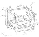
画像形成装置1の装置本体1aは、図2に示されるように、略直方体形状の枠体として形成された支持構造部材70を備えている。支持構造部材70は、装置本体1aの前面に配置されるフロントフレーム71と、装置本体1aの背面の略全体に配置されるリアフレーム72と、装置本体1aの四隅に立設した状態で配置されてフロントフレーム71とリアフレーム72を支持する4本の支柱フレーム73~76と、支柱フレーム73~76を装置本体1aの前後にわたり水平方向Yに沿って連結する複数の水平フレーム77~81と、装置本体1aの内部においてフロントフレーム71及びリアフレーム72を連結するよう水平に配置される平板状の内部フレーム82と、装置本体1aの前面に位置する左右の支柱フレーム73,74の下端部を連結するよう水平方向Xに沿って配置されるボトムフレーム83などから構成されている。
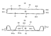
この実施の形態1に係るボトムフレーム83は、次のようにして、強度を高めるために組み合わせられる板材のエッジが長手方向と交差する方向に沿った断面の外部に突出する場合に比較して、安全性を向上させることが可能となっている。
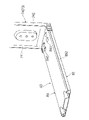
図14は、実施の形態2に係る画像形成装置のフレーム構造をそれぞれ示す断面構成図である。
1a…装置本体
10Y~10K…フルカラーの作像装置
11…感光体ドラム
70…支持構造部材
71…フロントフレーム
72…リアフレーム
73~76…支柱フレーム
83…ボトムフレーム
84…第1のフレーム部材
841…端縁
842…端縁
845…突出部
85…第2のフレーム部材
851…端縁
852…端縁
86…閉空間
Claims (9)
- 両端縁が折り曲げられて断面コ字形状に形成され、前記断面コ字形状の開口部同士が対向し且つ前記折り曲げられた両端縁どうしが重なるよう組み合わされて断面矩形状の閉空間を形成する一対のフレーム手段と、
前記一対のフレーム手段の少なくとも一方に設けられ、他方のフレーム手段の内面に接触するよう突出して前記閉空間の高さを規定する複数の突出部と、
を備え、
前記一対のフレーム手段の両端縁の折曲高さが前記突出部の突出高さ以下であり、
前記一対のフレーム手段は、引張試験における伸びの異なる板金からなるフレーム構造。 - 前記一方のフレーム手段は軟鋼からなり、前記他方のフレーム手段は高強度鋼からなる請求項1に記載のフレーム構造。
- 前記複数の突出部は、軟鋼からなる前記一方のフレーム手段のみに設けられる請求項2に記載のフレーム構造。
- 前記軟鋼からなる前記一方のフレーム手段の折り曲げられた両端縁は、前記高強度鋼からなる前記他方のフレーム手段の内側に位置するよう配置される請求項2に記載のフレーム構造。
- 前記一対のフレーム手段は、前記複数の突出部を介して接合されている請求項1に記載のフレーム構造。
- 前記複数の突出部は、長尺な平面矩形状に形成された前記一方のフレーム手段の四隅にそれぞれ配置されている請求項5に記載のフレーム構造。
- 前記一対のフレーム手段は、長手方向に沿った両端部で前記一対のフレーム手段と交差する方向にそれぞれ配置された交差フレーム手段と接合され、
前記交差フレーム手段は、前記一端部において前記一対のフレーム手段の長手方向に沿って配置された接合部を有し、
前記複数の突出部は、前記接合部における前記一対のフレーム手段の長手方向に沿った複数個所にわたり設けられる請求項1に記載のフレーム構造。 - 前記一対のフレーム手段のうち、一方のフレーム手段には、バーリング加工を施してネジ孔を形成し、前記ネジ孔に前記交差フレーム手段をネジ止めする請求項7に記載のフレーム構造。
- 画像形成手段が装着される装置本体を備え、
前記装置本体の一部を構成するフレーム構造として、前記請求項1~8のいずれかに記載のフレーム構造を用いた画像形成装置。
Priority Applications (1)
| Application Number | Priority Date | Filing Date | Title |
|---|---|---|---|
| JP2018152599A JP7192302B2 (ja) | 2018-08-14 | 2018-08-14 | フレーム構造及び画像形成装置 |
Applications Claiming Priority (1)
| Application Number | Priority Date | Filing Date | Title |
|---|---|---|---|
| JP2018152599A JP7192302B2 (ja) | 2018-08-14 | 2018-08-14 | フレーム構造及び画像形成装置 |
Publications (2)
| Publication Number | Publication Date |
|---|---|
| JP2020026859A JP2020026859A (ja) | 2020-02-20 |
| JP7192302B2 true JP7192302B2 (ja) | 2022-12-20 |
Family
ID=69619860
Family Applications (1)
| Application Number | Title | Priority Date | Filing Date |
|---|---|---|---|
| JP2018152599A Active JP7192302B2 (ja) | 2018-08-14 | 2018-08-14 | フレーム構造及び画像形成装置 |
Country Status (1)
| Country | Link |
|---|---|
| JP (1) | JP7192302B2 (ja) |
Families Citing this family (2)
| Publication number | Priority date | Publication date | Assignee | Title |
|---|---|---|---|---|
| JP7527846B2 (ja) | 2020-05-27 | 2024-08-05 | キヤノン株式会社 | シート搬送装置の支持フレームおよびシート搬送装置 |
| JP2024108206A (ja) | 2023-01-31 | 2024-08-13 | キヤノン株式会社 | 画像形成装置 |
Citations (5)
| Publication number | Priority date | Publication date | Assignee | Title |
|---|---|---|---|---|
| JP2001332878A (ja) | 2000-05-23 | 2001-11-30 | Denso Corp | 電子機器のネジ締め構造 |
| JP2002016384A (ja) | 2000-06-27 | 2002-01-18 | Canon Inc | 電気機器の筐体フレーム |
| JP2004291714A (ja) | 2003-03-26 | 2004-10-21 | Honda Motor Co Ltd | リアフロア構造 |
| JP2013250390A (ja) | 2012-05-31 | 2013-12-12 | Brother Ind Ltd | 定着装置 |
| JP2015220764A (ja) | 2014-05-14 | 2015-12-07 | 三菱電機株式会社 | 板材の螺子締結構造 |
Family Cites Families (2)
| Publication number | Priority date | Publication date | Assignee | Title |
|---|---|---|---|---|
| JPS5137773Y2 (ja) * | 1972-02-04 | 1976-09-16 | ||
| JP3304149B2 (ja) * | 1992-12-04 | 2002-07-22 | 株式会社リコー | 画像形成装置の構造体 |
-
2018
- 2018-08-14 JP JP2018152599A patent/JP7192302B2/ja active Active
Patent Citations (5)
| Publication number | Priority date | Publication date | Assignee | Title |
|---|---|---|---|---|
| JP2001332878A (ja) | 2000-05-23 | 2001-11-30 | Denso Corp | 電子機器のネジ締め構造 |
| JP2002016384A (ja) | 2000-06-27 | 2002-01-18 | Canon Inc | 電気機器の筐体フレーム |
| JP2004291714A (ja) | 2003-03-26 | 2004-10-21 | Honda Motor Co Ltd | リアフロア構造 |
| JP2013250390A (ja) | 2012-05-31 | 2013-12-12 | Brother Ind Ltd | 定着装置 |
| JP2015220764A (ja) | 2014-05-14 | 2015-12-07 | 三菱電機株式会社 | 板材の螺子締結構造 |
Also Published As
| Publication number | Publication date |
|---|---|
| JP2020026859A (ja) | 2020-02-20 |
Similar Documents
| Publication | Publication Date | Title |
|---|---|---|
| US8494409B2 (en) | Process cartridge and image forming apparatus | |
| KR100603656B1 (ko) | 컬러 화상 형성 장치 | |
| US7813683B2 (en) | Belt detaching device and image forming apparatus including belt detaching device | |
| JP4190237B2 (ja) | カラー画像形成装置 | |
| JP7192302B2 (ja) | フレーム構造及び画像形成装置 | |
| US20130236226A1 (en) | Image forming apparatus with compact sheet conveyance path | |
| US7162186B2 (en) | Image forming apparatus including a rotary member having a ⊃shaped cross section drive connecting member | |
| JP2022152386A (ja) | 搬送装置及び画像形成装置 | |
| EP1757995A1 (en) | Developer and electrophotographic image forming apparatus including the same | |
| JP2018031691A (ja) | トルク検出装置及び画像形成装置 | |
| US9989918B2 (en) | Image forming apparatus having defined arrangement of heat discharge duct | |
| US7079796B2 (en) | Color image forming apparatus with toner recycling mechanism | |
| JP2004013156A (ja) | 静電写真方式共通極性両面複製装置 | |
| JP2020085193A (ja) | 締結構造及び画像形成装置 | |
| US5132721A (en) | Multipurpose imaging apparatus | |
| US20250074727A1 (en) | Sheet feed device and image forming apparatus | |
| JP7027679B2 (ja) | 板金の折曲構造及び画像形成装置 | |
| JP4099497B2 (ja) | 画像形成装置 | |
| KR100837675B1 (ko) | 화상 형성 장치 | |
| US20070019983A1 (en) | Image forming apparatus having transfer belt | |
| JP6601050B2 (ja) | シート搬送装置及び画像形成装置 | |
| US20080317520A1 (en) | Image forming apparatus | |
| JP2003066685A (ja) | 画像形成装置 | |
| JPH04110871A (ja) | 画像形成装置 | |
| JP2026050597A (ja) | 画像形成システム |
Legal Events
| Date | Code | Title | Description |
|---|---|---|---|
| A621 | Written request for application examination |
Free format text: JAPANESE INTERMEDIATE CODE: A621 Effective date: 20210721 |
|
| A977 | Report on retrieval |
Free format text: JAPANESE INTERMEDIATE CODE: A971007 Effective date: 20220421 |
|
| A131 | Notification of reasons for refusal |
Free format text: JAPANESE INTERMEDIATE CODE: A131 Effective date: 20220510 |
|
| A521 | Request for written amendment filed |
Free format text: JAPANESE INTERMEDIATE CODE: A523 Effective date: 20220707 |
|
| A131 | Notification of reasons for refusal |
Free format text: JAPANESE INTERMEDIATE CODE: A131 Effective date: 20220809 |
|
| A521 | Request for written amendment filed |
Free format text: JAPANESE INTERMEDIATE CODE: A523 Effective date: 20221007 |
|
| TRDD | Decision of grant or rejection written | ||
| A01 | Written decision to grant a patent or to grant a registration (utility model) |
Free format text: JAPANESE INTERMEDIATE CODE: A01 Effective date: 20221108 |
|
| A61 | First payment of annual fees (during grant procedure) |
Free format text: JAPANESE INTERMEDIATE CODE: A61 Effective date: 20221121 |
|
| R150 | Certificate of patent or registration of utility model |
Ref document number: 7192302 Country of ref document: JP Free format text: JAPANESE INTERMEDIATE CODE: R150 |