JP7199529B2 - Control device, air environment adjustment system, air environment adjustment method, program, and recording medium - Google Patents

Control device, air environment adjustment system, air environment adjustment method, program, and recording medium Download PDF

Info

Publication number
JP7199529B2
JP7199529B2 JP2021521613A JP2021521613A JP7199529B2 JP 7199529 B2 JP7199529 B2 JP 7199529B2 JP 2021521613 A JP2021521613 A JP 2021521613A JP 2021521613 A JP2021521613 A JP 2021521613A JP 7199529 B2 JP7199529 B2 JP 7199529B2
Authority
JP
Japan
Prior art keywords
hot water
thermo
ventilation volume
ventilation
water supply
Prior art date
Legal status (The legal status is an assumption and is not a legal conclusion. Google has not performed a legal analysis and makes no representation as to the accuracy of the status listed.)
Active
Application number
JP2021521613A
Other languages
Japanese (ja)
Other versions
JPWO2020240685A1 (en
Inventor
芸青 范
Current Assignee (The listed assignees may be inaccurate. Google has not performed a legal analysis and makes no representation or warranty as to the accuracy of the list.)
Mitsubishi Electric Corp
Original Assignee
Mitsubishi Electric Corp
Priority date (The priority date is an assumption and is not a legal conclusion. Google has not performed a legal analysis and makes no representation as to the accuracy of the date listed.)
Filing date
Publication date
Application filed by Mitsubishi Electric Corp filed Critical Mitsubishi Electric Corp
Publication of JPWO2020240685A1 publication Critical patent/JPWO2020240685A1/ja
Application granted granted Critical
Publication of JP7199529B2 publication Critical patent/JP7199529B2/en
Active legal-status Critical Current
Anticipated expiration legal-status Critical

Links

Images

Classifications

    • FMECHANICAL ENGINEERING; LIGHTING; HEATING; WEAPONS; BLASTING
    • F24HEATING; RANGES; VENTILATING
    • F24FAIR-CONDITIONING; AIR-HUMIDIFICATION; VENTILATION; USE OF AIR CURRENTS FOR SCREENING
    • F24F11/00Control or safety arrangements
    • F24F11/30Control or safety arrangements for purposes related to the operation of the system, e.g. for safety or monitoring
    • F24F11/41Defrosting; Preventing freezing
    • FMECHANICAL ENGINEERING; LIGHTING; HEATING; WEAPONS; BLASTING
    • F24HEATING; RANGES; VENTILATING
    • F24FAIR-CONDITIONING; AIR-HUMIDIFICATION; VENTILATION; USE OF AIR CURRENTS FOR SCREENING
    • F24F11/00Control or safety arrangements
    • F24F11/30Control or safety arrangements for purposes related to the operation of the system, e.g. for safety or monitoring
    • F24F11/46Improving electric energy efficiency or saving
    • F24F11/47Responding to energy costs
    • FMECHANICAL ENGINEERING; LIGHTING; HEATING; WEAPONS; BLASTING
    • F24HEATING; RANGES; VENTILATING
    • F24FAIR-CONDITIONING; AIR-HUMIDIFICATION; VENTILATION; USE OF AIR CURRENTS FOR SCREENING
    • F24F11/00Control or safety arrangements
    • F24F11/62Control or safety arrangements characterised by the type of control or by internal processing, e.g. using fuzzy logic, adaptive control or estimation of values
    • F24F11/63Electronic processing
    • F24F11/64Electronic processing using pre-stored data
    • FMECHANICAL ENGINEERING; LIGHTING; HEATING; WEAPONS; BLASTING
    • F24HEATING; RANGES; VENTILATING
    • F24FAIR-CONDITIONING; AIR-HUMIDIFICATION; VENTILATION; USE OF AIR CURRENTS FOR SCREENING
    • F24F11/00Control or safety arrangements
    • F24F11/70Control systems characterised by their outputs; Constructional details thereof
    • F24F11/72Control systems characterised by their outputs; Constructional details thereof for controlling the supply of treated air, e.g. its pressure
    • F24F11/74Control systems characterised by their outputs; Constructional details thereof for controlling the supply of treated air, e.g. its pressure for controlling air flow rate or air velocity
    • F24F11/77Control systems characterised by their outputs; Constructional details thereof for controlling the supply of treated air, e.g. its pressure for controlling air flow rate or air velocity by controlling the speed of ventilators
    • FMECHANICAL ENGINEERING; LIGHTING; HEATING; WEAPONS; BLASTING
    • F24HEATING; RANGES; VENTILATING
    • F24FAIR-CONDITIONING; AIR-HUMIDIFICATION; VENTILATION; USE OF AIR CURRENTS FOR SCREENING
    • F24F7/00Ventilation
    • F24F7/007Ventilation with forced flow
    • YGENERAL TAGGING OF NEW TECHNOLOGICAL DEVELOPMENTS; GENERAL TAGGING OF CROSS-SECTIONAL TECHNOLOGIES SPANNING OVER SEVERAL SECTIONS OF THE IPC; TECHNICAL SUBJECTS COVERED BY FORMER USPC CROSS-REFERENCE ART COLLECTIONS [XRACs] AND DIGESTS
    • Y02TECHNOLOGIES OR APPLICATIONS FOR MITIGATION OR ADAPTATION AGAINST CLIMATE CHANGE
    • Y02BCLIMATE CHANGE MITIGATION TECHNOLOGIES RELATED TO BUILDINGS, e.g. HOUSING, HOUSE APPLIANCES OR RELATED END-USER APPLICATIONS
    • Y02B30/00Energy efficient heating, ventilation or air conditioning [HVAC]
    • Y02B30/70Efficient control or regulation technologies, e.g. for control of refrigerant flow, motor or heating

Landscapes

  • Engineering & Computer Science (AREA)
  • Mechanical Engineering (AREA)
  • General Engineering & Computer Science (AREA)
  • Chemical & Material Sciences (AREA)
  • Combustion & Propulsion (AREA)
  • Signal Processing (AREA)
  • Physics & Mathematics (AREA)
  • Fuzzy Systems (AREA)
  • Mathematical Physics (AREA)
  • Fluid Mechanics (AREA)
  • Air Conditioning Control Device (AREA)
  • Ventilation (AREA)
  • Heat-Pump Type And Storage Water Heaters (AREA)

Description

本発明は、室内の空気環境を調整する制御装置、空気環境調整システム、空気環境調整方法、プログラム、及びプログラムを記録した記録媒体に関し、特に給湯空調システムからの情報を基に換気装置の換気量制御を行うものに関する。 The present invention relates to a control device, an air environment adjustment system, an air environment adjustment method, a program, and a recording medium recording the program for adjusting the indoor air environment, and in particular, to a ventilation amount of a ventilation device based on information from a hot water supply air conditioning system. Concerning what controls.

従来、ヒートポンプ装置から選択的に給湯装置又は空調装置へ熱を供給する給湯空調システムが知られている。給湯空調システムは、給湯装置及び空調装置に同時に熱を供給することができない。そこで、給湯空調システムの電力抑制のための準備期間に、熱の供給を空調装置から給湯装置へ切り替え、その際に供給する熱量を通常よりも増加させる制御を行うことにより、空調装置と給湯装置との両方に十分な熱量を供給させている。(例えば、特許文献1参照)。 Conventionally, hot water supply and air conditioning systems are known that selectively supply heat from a heat pump device to a hot water supply device or an air conditioner. The hot water supply air conditioning system cannot supply heat to the water heater and the air conditioner at the same time. Therefore, during the preparation period for power reduction of the hot water supply air conditioning system, the supply of heat is switched from the air conditioner to the hot water supply system, and control is performed to increase the amount of heat supplied at that time than usual. and provide a sufficient amount of heat. (See Patent Document 1, for example).

特開2014-134343号公報JP 2014-134343 A

近年、住宅躯体の高気密高断熱化の進行により、24時間連続で換気が行われるのが一般的となり、1時間で室内容積の半分の空気を入れ替えるような設備を導入することが法律で決められている。一般に、換気装置と空調装置とはそれぞれ独立に運転されており、機能的に連携されていない。特許文献1に開示されているような給湯空調システムの場合、給湯装置に熱量が供給されている時は、空調装置による空調対象室の温度調整が出来ない。そのため、給湯装置に熱が供給されている時に換気装置が通常通り運転されているため、室内に外気が流入し、室温を大きく変動させてしまうという課題があった。 In recent years, due to the progress of high airtightness and high heat insulation of the housing frame, it has become common for ventilation to be performed continuously for 24 hours. It is Typically, ventilators and air conditioners operate independently and are not functionally linked. In the case of the hot water supply air conditioning system disclosed in Patent Document 1, the temperature of the air-conditioned room cannot be adjusted by the air conditioner when heat is supplied to the hot water supply device. Therefore, the ventilator is normally operated while heat is being supplied to the hot water supply system, so there is a problem that outside air flows into the room, causing the room temperature to fluctuate greatly.

本発明は、上記のような課題を解決するためになされたもので、給湯空調システムにより空調される室内において、給湯空調システムの運転モードの切り替えにより空調装置による温度調整がされない場合があっても、室温の変動を抑えることができる、室内の空気環境を調整する、制御装置、空気環境調整システム、空気環境調整方法、プログラム、及び記録媒体を提供することを目的とする。 SUMMARY OF THE INVENTION The present invention has been made to solve the above-described problems. An object of the present invention is to provide a control device, an air environment adjustment system, an air environment adjustment method, a program, and a recording medium that can suppress fluctuations in room temperature and adjust an indoor air environment.

本発明に係る制御装置は、給湯装置又は空調装置に熱を供給するヒートポンプを備える給湯空調システムの前記空調装置により室温が設定温度に調整される空調対象室内の空気を換気する換気装置の運転を制御する制御装置であって、前記給湯空調システムの運転情報及び前記室温を取得する通信部と、前記換気装置の換気量を制御する換気制御部と、を備え、前記運転情報は、前記給湯装置に前記ヒートポンプから熱が供給されている給湯運転、前記空調装置に前記ヒートポンプから熱が供給されている運転のうち、前記給湯空調システムが何れかの状態であるかの情報を含み、前記換気制御部は、前記通信部が取得した前記運転情報と前記室温とを取得し、前記運転情報と前記室温とに応じて前記換気量を変動させるものである。 A control device according to the present invention operates a ventilation device for ventilating air in a room to be air-conditioned, in which the room temperature is adjusted to a set temperature by the air conditioner of a hot water supply air conditioning system including a heat pump that supplies heat to the water heater or the air conditioner. A control device for controlling, comprising: a communication unit that acquires operation information of the hot water supply air conditioning system and the room temperature; hot water supply operation in which heat is supplied from the heat pump to the air conditioning system, and information indicating whether the hot water supply air conditioning system is in any of the operation in which heat is supplied to the air conditioner from the heat pump; The unit acquires the operating information and the room temperature acquired by the communication unit, and varies the ventilation volume according to the operating information and the room temperature.

本発明に係る空気環境調整システムは、上記の前記制御装置と、前記換気装置と、を備えるものである。 An air environment conditioning system according to the present invention includes the above control device and the ventilation device.

本発明に係る空気環境調整システムは、上記の前記制御装置と、前記換気装置と、前記給湯空調システムと、を備えるものである。 An air environment adjustment system according to the present invention includes the control device, the ventilation device, and the hot water supply air conditioning system.

本発明に係る空気環境調整方法は、給湯装置又は空調装置に熱を供給するヒートポンプを備える給湯空調システムの前記空調装置により室温が設定温度に調整される空調対象室内の空気を換気する空気環境調整方法であって、前記給湯空調システムの運転情報及び前記室温を取得し、前記運転情報は、前記給湯装置に前記ヒートポンプから熱が供給されている給湯運転及び前記空調装置に前記ヒートポンプから熱が供給されている運転のうち、前記給湯空調システムが何れかの状態であるかの情報を含み、前記運転情報と前記室温とに応じて前記空調対象室内の換気量を変動させるものである。 An air environment adjustment method according to the present invention provides air environment adjustment for ventilating air in a room to be air-conditioned, in which the room temperature is adjusted to a set temperature by the air conditioner of a hot water supply air conditioning system including a heat pump that supplies heat to the water heater or the air conditioner. In the method, the operation information and the room temperature of the hot water supply and air conditioning system are obtained, and the operation information is a hot water supply operation in which heat is supplied from the heat pump to the water heater and heat is supplied to the air conditioner from the heat pump. It includes information as to which state the hot water supply air-conditioning system is in among the operations being performed, and varies the ventilation amount in the air-conditioned room according to the operation information and the room temperature.

本発明に係るプログラムは、給湯装置又は空調装置に熱を供給するヒートポンプを備える給湯空調システムの前記空調装置により室温が設定温度に調整される空調対象室内の空気を換気する換気装置の運転を制御するコンピュータを、前記給湯空調システムの運転情報及び前記室温を取得する手段と、前記給湯装置に前記ヒートポンプから熱が供給されている給湯運転及び前記空調装置に前記ヒートポンプから熱が供給されている運転のうち、前記給湯空調システムが何れかの状態であるかの情報を含む前記運転情報と前記室温とに応じて前記換気装置の換気量を変動させる手段として機能させるものである。 A program according to the present invention controls the operation of a ventilator for ventilating air in a room to be air-conditioned, in which the room temperature is adjusted to a set temperature by the air conditioner of a hot water supply air conditioning system equipped with a heat pump that supplies heat to the water heater or the air conditioner. means for acquiring the operating information of the hot water supply and air conditioning system and the room temperature; Among these, it functions as a means for varying the ventilation volume of the ventilator according to the operating information including the information indicating which state the hot water supply and air conditioning system is in and the room temperature.

本発明に係る記録媒体は、上記プログラムを記録したコンピュータ読み取り可能なものである。 A recording medium according to the present invention is a computer-readable medium recording the above program.

本発明によれば、室温の低下度合に応じて換気装置の換気量を変動させることができるため、空調対象室の室温変動を緩和することができる。 According to the present invention, it is possible to change the ventilation rate of the ventilation device according to the degree of decrease in the room temperature, so that it is possible to mitigate the room temperature fluctuations in the air-conditioned room.

実施の形態1における空気環境調整システム100の概略構成図である。1 is a schematic configuration diagram of an air environment conditioning system 100 according to Embodiment 1. FIG. 図1の空気環境調整システム100の詳細構成図である。FIG. 2 is a detailed configuration diagram of the air environment conditioning system 100 of FIG. 1; 実施の形態1に係る制御装置10の一例を示すブロック図である。1 is a block diagram showing an example of a control device 10 according to Embodiment 1; FIG. 実施の形態1に係る空気環境調整システム100の制御フローの一例である。4 is an example of a control flow of the air environment adjustment system 100 according to Embodiment 1. FIG. 実施の形態1に係る空気環境調整システム100の運転の一例である。It is an example of operation of the air environment conditioning system 100 according to Embodiment 1. FIG. 図5の給湯運転における給湯空調システム30の状態を示す回路図である。6 is a circuit diagram showing the state of the hot water supply air conditioning system 30 in the hot water supply operation of FIG. 5. FIG. 図5の通常暖房運転における給湯空調システム30の状態を示す回路図である。FIG. 6 is a circuit diagram showing the state of the hot water supply air conditioning system 30 in the normal heating operation of FIG. 5; 実施の形態1に係る制御装置10の制御フローの一例である。4 is an example of a control flow of the control device 10 according to Embodiment 1. FIG. 実施の形態1に係る制御装置10の制御フローの一例である。4 is an example of a control flow of the control device 10 according to Embodiment 1. FIG. 実施の形態1に係る空気環境調整システム100の運転の一例である。It is an example of operation of the air environment conditioning system 100 according to Embodiment 1. FIG. 実施の形態1に係る空気環境調整システム100の運転の一例である。It is an example of operation of the air environment conditioning system 100 according to Embodiment 1. FIG. 図10及び図11の除霜暖房運転における給湯空調システム30の状態を示す回路図である。FIG. 12 is a circuit diagram showing the state of the hot water supply air conditioning system 30 in the defrosting heating operation of FIGS. 10 and 11. FIG. 実施の形態1に係る制御装置10の制御フローの一例である。4 is an example of a control flow of the control device 10 according to Embodiment 1. FIG. 実施の形態1に係る空気環境調整システム100の運転の一例である。It is an example of operation of the air environment conditioning system 100 according to Embodiment 1. FIG. 実施の形態1に係る給湯空調システム30がサーモ運転している時の換気装置20及び給湯空調システム30の運転の一例である。1 shows an example of operation of ventilator 20 and hot water supply air conditioning system 30 when hot water supply air conditioning system 30 according to Embodiment 1 is in thermo operation. 実施の形態1に係る制御装置10の制御フローの一例である。4 is an example of a control flow of the control device 10 according to Embodiment 1. FIG. 実施の形態1に係る空気環境調整システム100における給湯空調システム30の圧縮機46の運転パターンの一例である。It is an example of the operation pattern of the compressor 46 of the hot water supply air conditioning system 30 in the air environment adjustment system 100 according to Embodiment 1. FIG. 実施の形態1に係る空気環境調整システム100の給湯空調システム30の運転履歴情報の一例を示している。An example of operation history information of the hot water supply air conditioning system 30 of the air environment adjustment system 100 according to Embodiment 1 is shown. 図17の第3のパターンにおける換気装置20の換気量と給湯空調システム30のサーモ運転切り替えの閾値との相関を示す図である。FIG. 18 is a diagram showing the correlation between the ventilation amount of the ventilation device 20 and the threshold value for switching to the thermo mode of the hot water supply air conditioning system 30 in the third pattern of FIG. 17;

以下、実施の形態について、図面を用いて詳細に説明する。また、実施の形態で説明する具体的な構造及び設定例は一例を示すだけであり、これらに限定されない。 Hereinafter, embodiments will be described in detail with reference to the drawings. In addition, the specific structure and setting examples described in the embodiments are merely examples, and the present invention is not limited to these.

実施の形態において、通信とは、無線通信及び有線通信は勿論、無線通信と有線通信とが混在した通信であってもよい。例えば、ある区間では無線通信が行われ、他の空間では有線通信が行われるようなものであってもよい。また、ある装置から他の装置への通信が有線通信で行われ、他の装置からある装置への通信が無線通信で行われるようなものであってもよい。 In the embodiment, the communication may be a mixture of wireless communication and wired communication as well as wireless communication and wired communication. For example, wireless communication may be performed in a certain section, and wired communication may be performed in another space. Alternatively, communication from one device to another device may be performed by wire communication, and communication from another device to another device may be performed by wireless communication.

実施の形態1.
図1は、実施の形態1における空気環境調整システム100の概略構成図である。この図1に基づいて空気環境調整システム100の概略構成について説明する。空気環境調整システム100は、制御装置10と、空調対象室1内を換気する換気装置20と、空調対象室1内を空調する給湯空調システム30とを備えている。制御装置10は、換気装置20及び給湯空調システム30と通信可能に接続されている。制御装置10は、少なくとも、給湯空調システム30からの運転情報を取得して、換気装置20の運転を制御できる様に構成されている。これにより、空気環境調整システム100は、空調対象室1の空気の温度を調整する給湯空調システム30と、空調対象室1内の空気と外気との交換量を制御する換気装置20と、を協調させて制御することができる。
Embodiment 1.
FIG. 1 is a schematic configuration diagram of an air environment conditioning system 100 according to Embodiment 1. FIG. A schematic configuration of the air environment adjustment system 100 will be described based on FIG. The air environment adjustment system 100 includes a control device 10 , a ventilation device 20 for ventilating the inside of the air-conditioned room 1 , and a hot water supply air conditioning system 30 for air-conditioning the inside of the air-conditioned room 1 . Control device 10 is communicably connected to ventilation device 20 and hot water supply air conditioning system 30 . The control device 10 is configured to acquire at least operation information from the hot water supply air conditioning system 30 and control the operation of the ventilation device 20 . As a result, the air environment adjustment system 100 coordinates the hot water supply air conditioning system 30 that adjusts the temperature of the air in the air-conditioned room 1 and the ventilation device 20 that controls the amount of exchange between the air in the air-conditioned room 1 and the outside air. can be controlled by

空気環境調整システム100は、インターネット等の手段により接続された端末である外部端末90と通信できる様に構成されていても良い。以下の説明において、制御装置10が行う情報処理は、外部端末90で行われても良い。つまり、給湯空調システム30からの運転情報を外部端末90に送信し、運転情報を外部端末90で処理し、外部端末90から換気装置20に制御指示を送信しても良い。外部端末90は、例えば、外部に設置されたコンピュータ又はサーバである。また、外部端末90は、クラウドコンピューティングを利用して構成されていても良い。 The air environment adjustment system 100 may be configured to communicate with an external terminal 90, which is a terminal connected by means such as the Internet. In the following description, information processing performed by the control device 10 may be performed by the external terminal 90 . That is, the operation information from the hot water supply air conditioning system 30 may be transmitted to the external terminal 90 , the operation information may be processed by the external terminal 90 , and the control instruction may be transmitted from the external terminal 90 to the ventilation device 20 . The external terminal 90 is, for example, a computer or server installed outside. Also, the external terminal 90 may be configured using cloud computing.

また、制御装置10は、図1に示される様に独立していても良いが、換気装置20、給湯空調システム30、又はその他の装置と一体に構成されていても良い。 Further, the control device 10 may be independent as shown in FIG. 1, but may be configured integrally with the ventilation device 20, the hot water supply air conditioning system 30, or other devices.

図2は、図1の空気環境調整システム100の詳細構成図である。図2に基づいて、換気装置20及び給湯空調システム30の概略構成を含めた空気環境調整システム100の構成について説明する。まず、換気装置20の概略構成について説明する。 FIG. 2 is a detailed configuration diagram of the air environment conditioning system 100 of FIG. Based on FIG. 2, the configuration of the air environment adjustment system 100 including the schematic configuration of the ventilation device 20 and the hot water supply air conditioning system 30 will be described. First, a schematic configuration of the ventilator 20 will be described.

(換気装置20)
換気装置20は、吸気パイプ21と、排気パイプ22と、全熱交換部23と、外気直接導入バイパス24と、を備える。全熱交換部23は、空調対象室1内から排出される空気のエネルギーを回収するものである。吸気パイプ21には吸気ファン25、排気パイプ22には排気ファン26、外気直接導入バイパス24にはバイパスファン27がそれぞれ設置されている。
(Ventilator 20)
The ventilator 20 includes an intake pipe 21 , an exhaust pipe 22 , a total heat exchange section 23 and an external air direct introduction bypass 24 . The total heat exchange section 23 recovers the energy of the air discharged from the air-conditioned room 1 . An intake fan 25 is installed in the intake pipe 21, an exhaust fan 26 is installed in the exhaust pipe 22, and a bypass fan 27 is installed in the external air direct introduction bypass 24, respectively.

換気装置20は、吸気パイプ21と外気直接導入バイパス24との接続部29に開閉部29aが設けられている。接続部29は、吸気パイプ21の吸入口21aから全熱交換部23に到る途中に設置されている。開閉部29aは、開放されることにより吸気パイプ21からの空気を全熱交換部23を経ずに空調対象室1に導入することができる。 The ventilator 20 is provided with an opening/closing portion 29 a at a connecting portion 29 between the intake pipe 21 and the external air direct introduction bypass 24 . The connecting portion 29 is installed on the way from the intake port 21 a of the intake pipe 21 to the total heat exchange portion 23 . The opening/closing portion 29 a can introduce the air from the intake pipe 21 into the air-conditioned room 1 without passing through the total heat exchange portion 23 by being opened.

換気装置20は、吸気ファン25及び排気ファン26を作動させることにより、給気及び排気を行う。開閉部29aが閉じられている場合、吸気ファン25により吸気パイプ21に導入された室外の空気は、全熱交換部23を経て空調対象室1に導入される。また、開閉部29aが開放されている又は閉鎖されているに拘わらず、排気ファン26により排気パイプ22に導入された空調対象室1内の空気は、全熱交換部23を経て排気口22aから室外に排出される。 The ventilator 20 supplies and exhausts air by operating an intake fan 25 and an exhaust fan 26 . When the opening/closing portion 29 a is closed, the outdoor air introduced into the intake pipe 21 by the intake fan 25 is introduced into the air-conditioned room 1 through the total heat exchange portion 23 . In addition, regardless of whether the opening/closing portion 29a is open or closed, the air in the air-conditioned room 1 introduced into the exhaust pipe 22 by the exhaust fan 26 passes through the total heat exchange portion 23 and exits from the exhaust port 22a. discharged outdoors.

換気装置20は、必要に応じ、開閉部29aの切り替えと、吸気ファン25、排気ファン26、及びバイパスファン27の出力を変動させることができる。換気装置20は、空調対象室1の換気量を適宜変動させることができ、空調対象室1から排出される空気からの熱回収も適宜変動させることができる。 The ventilator 20 can switch the opening/closing portion 29a and change the outputs of the intake fan 25, the exhaust fan 26, and the bypass fan 27 as necessary. The ventilator 20 can appropriately vary the ventilation amount of the air-conditioned room 1 and can also appropriately vary the heat recovery from the air discharged from the air-conditioned room 1 .

換気装置20は、基本的に24時間、連続的に運転して空調対象室1を換気するものである。換気装置20は、通常運転において、1時間で空調対象室1の容積の半分の空気を換気するように設定されている。この換気装置20の通常運転における換気量を「0.5回/h」と表す。換気装置20の通常運転時の換気量は、一例でありこの値のみに限定されるものではなく、必要に応じ変更することができる。換気装置20の換気量は、制御により変動させることができる。例えば換気量が「0.1回/h」に設定された場合は、換気装置20は、1時間に空調対象室1の容積の1/10の量の空気を換気する。 The ventilator 20 basically operates continuously for 24 hours to ventilate the air-conditioned room 1 . The ventilator 20 is set to ventilate half the volume of the air-conditioned room 1 in one hour during normal operation. The ventilation rate in normal operation of this ventilator 20 is expressed as "0.5 times/h". The ventilation volume during normal operation of the ventilator 20 is an example and is not limited to this value, and can be changed as required. The ventilation volume of the ventilator 20 can be varied by control. For example, when the ventilation rate is set to "0.1 times/h", the ventilator 20 ventilates 1/10 of the volume of the air-conditioned room 1 in one hour.

実施の形態1において、換気装置20は、空調対象室1の室温を調整する給湯空調システム30の運転状態に応じて運転が制御されるものである。図2に示されている換気制御端末12は、換気装置20の運転を制御するための端末であり、換気装置20の運転開始、運転停止、換気量の変更等を実行させるためのものである。換気装置20は、手動でも運転状態を設定することができるが、実施の形態1においては、制御装置10により制御される場合について説明する。換気制御端末12は、換気装置20と一体に構成されていても別体に構成されていても良い。また、換気制御端末12は、制御装置10と一体に構成されていても良い。 In Embodiment 1, the operation of the ventilator 20 is controlled according to the operating state of the hot water supply air conditioning system 30 that adjusts the room temperature of the air-conditioned room 1 . The ventilation control terminal 12 shown in FIG. 2 is a terminal for controlling the operation of the ventilation device 20, and is used to start and stop the operation of the ventilation device 20, change the ventilation volume, and the like. . The operating state of the ventilator 20 can also be set manually, but in the first embodiment, the case of being controlled by the control device 10 will be described. The ventilation control terminal 12 may be configured integrally with the ventilator 20 or may be configured separately. Also, the ventilation control terminal 12 may be configured integrally with the control device 10 .

(給湯空調システム30)
次に、給湯空調システム30の概略構成について説明する。給湯空調システム30は、給湯装置40、空調装置31、ヒートポンプ装置32、及びタンク60から構成されるものである。ヒートポンプ装置32は、冷凍サイクル回路33を備えており、内部の冷媒を圧縮及び膨張させながら循環させることにより利用側熱交換器43にて水と冷媒との熱交換を行い、タンク60に湯として蓄熱させ、又は空調装置31に湯を供給するものである。給湯装置40は、タンク60に貯留された湯を給湯ポンプ63により、給湯端末41に湯を供給するものである。また、空調装置31は、タンク60に貯留された湯又は利用側熱交換器43において加熱された湯を、暖房循環ポンプ62を用いて空調対象室1に設置されたパイプ等に循環させることにより、室温を調整するものである。空調装置31は、例えば、床暖房等である。
(Hot water supply air conditioning system 30)
Next, a schematic configuration of the hot water supply air conditioning system 30 will be described. The hot water supply air conditioning system 30 includes a hot water supply device 40 , an air conditioning device 31 , a heat pump device 32 and a tank 60 . The heat pump device 32 includes a refrigeration cycle circuit 33 , and circulates the internal refrigerant while compressing and expanding it, thereby performing heat exchange between water and the refrigerant in the user-side heat exchanger 43 , and supplying hot water to the tank 60 . It stores heat or supplies hot water to the air conditioner 31 . Hot water supply device 40 supplies hot water stored in tank 60 to hot water supply terminal 41 by means of hot water supply pump 63 . In addition, the air conditioner 31 circulates the hot water stored in the tank 60 or the hot water heated in the user-side heat exchanger 43 through a pipe or the like installed in the air-conditioned room 1 using the heating circulation pump 62. , to adjust the room temperature. The air conditioner 31 is, for example, a floor heater.

ヒートポンプ装置32は、圧縮機46、四方弁42、利用側熱交換器43、膨張装置44、熱源側熱交換器45を順次冷媒配管で接続された冷凍サイクル回路33を有する。ヒートポンプ装置32の室外に配置された筐体の内部には、圧縮機46、四方弁42、膨張装置44、及び熱源側熱交換器45が設置されており、熱源側熱交換器45の近傍には、室外の空気を熱源側熱交換器45に送る室外送風機49が設置されている。また、利用側熱交換器43は、ヒートポンプ装置32の筐体の内部、又はタンク60が設置されている筐体の内部に設置されており、内部に冷媒が流動する流路と水が流動する流路とが設けられている。利用側熱交換器43にて冷媒と水との間で熱交換が行われ、加熱された水は、流路切替装置47等により制御されてタンク60又は空調装置31に供給される。 The heat pump device 32 has a refrigeration cycle circuit 33 in which a compressor 46, a four-way valve 42, a utilization side heat exchanger 43, an expansion device 44, and a heat source side heat exchanger 45 are sequentially connected by refrigerant piping. A compressor 46, a four-way valve 42, an expansion device 44, and a heat source side heat exchanger 45 are installed inside a housing arranged outside the heat pump device 32. is installed with an outdoor fan 49 that sends outdoor air to the heat source side heat exchanger 45 . The user-side heat exchanger 43 is installed inside the housing of the heat pump device 32 or inside the housing in which the tank 60 is installed. A flow path is provided. Heat is exchanged between the refrigerant and water in the user-side heat exchanger 43 , and the heated water is supplied to the tank 60 or the air conditioner 31 under the control of the channel switching device 47 and the like.

図2に示されている給湯空調制御端末13は、給湯空調システム30の運転を制御するための端末であり、設定された室温の設定温度T0及び給湯端末41に供給する湯の温度に基づいて、給湯空調システム30の運転を実行させるためのものである。具体的には、ヒートポンプ装置32の圧縮機46、膨張装置44、空調装置31の暖房循環ポンプ62、給湯装置40の給湯ポンプ63、及び流路切替装置47等の動作を制御する。 Hot water supply air-conditioning control terminal 13 shown in FIG. , for executing the operation of the hot water supply and air conditioning system 30 . Specifically, it controls the operations of the compressor 46 of the heat pump device 32, the expansion device 44, the heating circulation pump 62 of the air conditioner 31, the hot water pump 63 of the hot water heater 40, the channel switching device 47, and the like.

給湯空調システム30の空調装置31は、空調対象室1の空気の温度が、例えばリモコンなどにより、設定温度T0となるように暖房能力を調整する。また、給湯空調システム30の給湯装置40は、設定された湯温になるように、タンク60から給湯端末41に供給される湯量を調整する。給湯空調制御端末13は、給湯空調システム30と一体に構成されていても別体に構成されていても良い。また、給湯空調制御端末13は、給湯装置40の制御をする端末と空調装置31の制御をする端末とに分かれて構成されていても良い。さらに、給湯空調制御端末13は、制御装置10と一体に構成されていても良い。 The air conditioner 31 of the hot water supply air-conditioning system 30 adjusts the heating capacity so that the temperature of the air in the room 1 to be air-conditioned reaches the set temperature T0 by, for example, a remote controller. In addition, hot water supply device 40 of hot water supply air conditioning system 30 adjusts the amount of hot water supplied from tank 60 to hot water supply terminal 41 so that the hot water temperature reaches the set temperature. The hot water supply air conditioning control terminal 13 may be configured integrally with the hot water supply air conditioning system 30 or may be configured separately. Hot water supply and air conditioning control terminal 13 may be divided into a terminal for controlling hot water supply device 40 and a terminal for controlling air conditioning device 31 . Furthermore, the hot water supply air conditioning control terminal 13 may be configured integrally with the control device 10 .

(制御装置10)
制御装置10は、給湯空調システム30から取得した運転情報に基づき、換気装置20の運転を制御するものである。図2に示される様に、制御装置10は、室温検知器11、換気制御端末12、及び給湯空調制御端末13のそれぞれと通信可能に接続されている。室温検知器11は、空調対象室1の空気の温度を検知する。制御装置10は、室温検知器11から室温情報を取得する。ただし、制御装置10は、給湯空調制御端末13から給湯空調システム30が備える温度センサからの温度情報を取得し、空調対象室1の空気の温度として利用することもできる。制御装置10は、室温検知器11又は給湯空調システム30から得た運転情報に基づき、所定の条件を満たした場合の換気装置20の換気量を設定し、換気制御端末12に指示を送信する。また、制御装置10は、所定の条件において給湯空調システム30の運転状態を変動させる指示を給湯空調制御端末13に送信する。
(control device 10)
The control device 10 controls the operation of the ventilation device 20 based on the operation information acquired from the hot water supply air conditioning system 30 . As shown in FIG. 2, the control device 10 is communicably connected to each of the room temperature detector 11, the ventilation control terminal 12, and the hot water supply air conditioning control terminal 13. As shown in FIG. A room temperature detector 11 detects the temperature of the air in the air-conditioned room 1 . The control device 10 acquires room temperature information from the room temperature detector 11 . However, the control device 10 can also acquire temperature information from a temperature sensor provided in the hot water supply air conditioning system 30 from the hot water supply air conditioning control terminal 13 and use it as the temperature of the air in the air conditioning target room 1 . Based on the operation information obtained from the room temperature detector 11 or the hot water supply air conditioning system 30 , the control device 10 sets the ventilation volume of the ventilation device 20 when a predetermined condition is satisfied, and transmits an instruction to the ventilation control terminal 12 . Further, control device 10 transmits to hot water supply air conditioning control terminal 13 an instruction to change the operating state of hot water supply air conditioning system 30 under a predetermined condition.

図3は、実施の形態1に係る制御装置10の一例を示すブロック図である。制御装置10は、給湯空調システム30から運転情報を取得する給湯空調システム運転状態検知部54と、室温検知器11等から空調対象室1の空気の温度情報を取得する室温検知部55と、を備える通信部53を有する。通信部53は、室温検知器11、換気制御端末12、給湯空調制御端末13、及び外部端末90と通信可能に接続されており、各部からの情報の取得及び各部へ情報の送信を行う。また、制御装置10は、換気装置20及び給湯空調システム30の制御を行う制御部51を備える。制御部51は、運転情報等を記憶する記憶部52及び運転情報を基に換気量を決定し換気装置20の制御を行う換気制御部57、及び空調装置31の暖房循環ポンプ62等の制御を行う給湯空調制御部58を備える。 FIG. 3 is a block diagram showing an example of the control device 10 according to Embodiment 1. As shown in FIG. The control device 10 includes a hot water supply air conditioning system operating state detection unit 54 that acquires operation information from the hot water supply air conditioning system 30, and a room temperature detection unit 55 that acquires air temperature information in the air conditioning target room 1 from the room temperature detector 11 or the like. A communication unit 53 is provided. The communication unit 53 is communicably connected to the room temperature detector 11, the ventilation control terminal 12, the hot water supply air conditioning control terminal 13, and the external terminal 90, and acquires information from and transmits information to each unit. The control device 10 also includes a control unit 51 that controls the ventilation device 20 and the hot water supply air conditioning system 30 . The control unit 51 controls a storage unit 52 that stores operation information and the like, a ventilation control unit 57 that determines the amount of ventilation based on the operation information and controls the ventilation device 20, and a heating circulation pump 62 of the air conditioner 31. A hot water supply air conditioning control unit 58 is provided.

制御部51は、例えば、CPU(Central Processing Unit)、ROM(Read Only Memory)及びRAM(Random Access Memory)を備える。CPUは、中央処理装置、中央演算装置、プロセッサ、マイクロプロセッサ、マイクロコンピュータ又はDSP(Digital Signal Processor)ともいう。制御部51において、CPUは、ROMに格納されたプログラム及びデータを読み出し、RAMをワークエリアとして用いて、制御装置10を統括制御するものである。 The control unit 51 includes, for example, a CPU (Central Processing Unit), a ROM (Read Only Memory), and a RAM (Random Access Memory). The CPU is also called a central processing unit, a central processing unit, a processor, a microprocessor, a microcomputer, or a DSP (Digital Signal Processor). In the control unit 51, the CPU reads out programs and data stored in the ROM, uses the RAM as a work area, and controls the control device 10 as a whole.

記憶部52は、例えば、フラッシュメモリ、EPROM(Erasable Programmable ROM)、EEPROM(Electrically Erasable Programmable ROM)等の不揮発性の半導体メモリであって、いわゆる二次記憶装置としての役割を担うものである。実施の形態1において、記憶部52は、通信部53で取得された運転情報を記憶する。また、記憶部52は、通信部53で取得された室温情報を記憶する。さらに、記憶部52は、制御装置10と空気環境調整システム100を構成する各部とが通信するためのプログラム及びデータ等を記憶する。また、例えば制御装置10が換気装置20を直接制御する場合は、制御するためのプログラム及びデータを記憶する。 The storage unit 52 is, for example, a non-volatile semiconductor memory such as a flash memory, EPROM (Erasable Programmable ROM), EEPROM (Electrically Erasable Programmable ROM), etc., and serves as a so-called secondary storage device. In Embodiment 1, the storage unit 52 stores the driving information acquired by the communication unit 53 . The storage unit 52 also stores room temperature information acquired by the communication unit 53 . Furthermore, the storage unit 52 stores programs, data, and the like for communication between the control device 10 and each unit that configures the air environment adjustment system 100 . Further, for example, when the control device 10 directly controls the ventilation device 20, it stores programs and data for control.

通信部53は、室温検知器11、換気制御端末12、給湯空調制御端末13、及び外部端末90と通信するための通信インタフェースを備える。 The communication unit 53 includes a communication interface for communicating with the room temperature detector 11 , the ventilation control terminal 12 , the hot water supply air conditioning control terminal 13 and the external terminal 90 .

計時部56は、例えば、RTC(Real Time Clock)を備えており、給湯空調システム30のサーモオン制御及びサーモオフ制御の計時を行う計時デバイスである。 The clock unit 56 includes, for example, an RTC (Real Time Clock), and is a clock device that clocks thermo-on control and thermo-off control of the hot water supply air conditioning system 30 .

(空気環境調整システム100の動作)
実施の形態1において、給湯空調システム30の運転は、給湯運転、通常暖房運転、サーモ運転、及び除霜運転の4つを備える。給湯運転は、ヒートポンプ装置32において水を加熱し、タンク60に湯を貯留する運転である。通常暖房運転は、ヒートポンプ装置32おいて加熱された湯を空調装置31に供給することにより、連続的に空調装置31に熱を供給し、空調対象室1の室温を調整する運転である。サーモ運転は、空調対象室1の室温が設定温度T0を基準として所定の範囲内にあるときの運転である。サーモ運転においては、空調対象室1内の空気の温度を所定の範囲に維持するために、空調装置31及びヒートポンプ装置32は、運転及び停止を繰り返す。除霜運転は、ヒートポンプ装置32の熱源側熱交換器45に付着した霜又は氷を除去するために行うものであり、熱源側熱交換器45の熱交換能力を確保するために必要な運転である。
(Operation of air environment adjustment system 100)
In Embodiment 1, hot water supply air-conditioning system 30 has four operations: hot water supply operation, normal heating operation, thermo operation, and defrosting operation. The hot water supply operation is an operation in which water is heated in heat pump device 32 and hot water is stored in tank 60 . The normal heating operation is an operation in which hot water heated by the heat pump device 32 is supplied to the air conditioner 31 to continuously supply heat to the air conditioner 31 to adjust the room temperature of the air-conditioned room 1 . Thermo operation is an operation when the room temperature of the air-conditioned room 1 is within a predetermined range with reference to the set temperature T0. In thermo-operation, the air conditioner 31 and the heat pump device 32 repeat operation and stop in order to maintain the temperature of the air in the air-conditioned room 1 within a predetermined range. The defrosting operation is performed to remove frost or ice attached to the heat source side heat exchanger 45 of the heat pump device 32, and is an operation necessary to ensure the heat exchange capacity of the heat source side heat exchanger 45. be.

制御装置10は、給湯空調制御端末13から運転情報を取得する。実施の形態1において、運転情報は、給湯空調システム30のヒートポンプ装置32が備える圧縮機46の周波数である。圧縮機46は、インバータにより回転数が制御され、室内の冷房負荷又は暖房負荷に応じて回転を増加、減少、又は停止する。制御装置10は、給湯空調制御端末13から圧縮機46の周波数を運転情報として取得する。制御装置10は、圧縮機46の周波数を運転情報として処理し、必要な換気量を決定し、指示として換気制御端末12に送信する。換気制御端末12は、換気装置20の具体的な動作を制御する。 The control device 10 acquires operation information from the hot water supply air conditioning control terminal 13 . In Embodiment 1, the operating information is the frequency of compressor 46 provided in heat pump device 32 of hot water supply air conditioning system 30 . The rotation speed of the compressor 46 is controlled by an inverter, and the rotation is increased, decreased, or stopped according to the indoor cooling load or heating load. The control device 10 acquires the frequency of the compressor 46 from the hot water supply air conditioning control terminal 13 as operation information. The controller 10 processes the frequency of the compressor 46 as operating information, determines the required ventilation volume, and transmits it as an instruction to the ventilation control terminal 12 . The ventilation control terminal 12 controls specific operations of the ventilation device 20 .

上記の給湯運転、通常暖房運転、サーモ運転、及び除霜運転の4種類の運転は、同時に行うことが出来ない。従って、これらの運転において、空調装置31が作動していない場合は、空調対象室1の室温が調整されない。空調対象室1は、換気装置20により常時換気されており、基本的には通常換気量Q0である0.5回/hの換気量で換気が行われている。すると、給湯空調システム30が室温が調整出来ないモードで運転されている場合は、空調対象室1は、換気が行われ、室外の低温の空気が流入し、室温が急速に低下することになる。室温が低下すると空調対象室1の快適性が損なわれるだけでなく、空調対象室1の温度を設定温度T0に戻すために、暖房能力が高い状態で空調装置31を運転させる必要があり、エネルギー損失が増大するという課題があった。実施の形態1においては、制御装置10により、給湯空調システム30の運転情報及び室温情報を基に、換気装置20の換気量を制御することにより、空調装置31が作動していない場合には換気量を低下させて、空調装置31が作動している場合には換気量を増加させて、室温の変動を抑制している。 The four types of operations, ie, hot water supply operation, normal heating operation, thermostat operation, and defrosting operation, cannot be performed at the same time. Therefore, in these operations, if the air conditioner 31 is not operating, the room temperature of the air-conditioned room 1 is not adjusted. The air-conditioned room 1 is constantly ventilated by the ventilation device 20, and is basically ventilated at a ventilation rate of 0.5 times/h, which is the normal ventilation rate Q0. Then, when the hot water supply air-conditioning system 30 is operated in a mode in which the room temperature cannot be adjusted, the room 1 to be air-conditioned is ventilated, and low-temperature air from the outside flows in, resulting in a rapid decrease in room temperature. . When the room temperature drops, not only does the comfort of the air-conditioned room 1 deteriorate, but in order to return the temperature of the air-conditioned room 1 to the set temperature T0, it is necessary to operate the air conditioner 31 with a high heating capacity. There was a problem that the loss increased. In Embodiment 1, the control device 10 controls the ventilation rate of the ventilation device 20 based on the operation information and the room temperature information of the hot water supply air conditioning system 30, so that when the air conditioning device 31 is not operating, ventilation is performed. When the amount is decreased and the air conditioner 31 is operating, the ventilation amount is increased to suppress fluctuations in the room temperature.

(給湯空調システム30の運転状態に応じた換気装置20の制御)
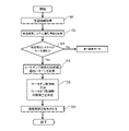
図4は、実施の形態1に係る空気環境調整システム100の制御フローの一例である。実施の形態1に係る空気環境調整システム100の制御装置10は、図4の制御フローに基づき、給湯空調システム30の運転状態が給湯運転、通常暖房運転、サーモ運転、及び除霜運転の4種類の運転の何れに該当するかを判定する。そして、制御装置10は、それぞれの運転に応じて換気装置20の換気量を制御する。
(Control of ventilator 20 according to operation state of hot water supply air conditioning system 30)
FIG. 4 is an example of a control flow of the air environment adjustment system 100 according to Embodiment 1. FIG. The control device 10 of the air environment adjustment system 100 according to Embodiment 1 has four operating states of the hot water supply air conditioning system 30: hot water supply operation, normal heating operation, thermo-operation, and defrosting operation, based on the control flow of FIG. It is determined whether it corresponds to any of the driving of. Then, the controller 10 controls the ventilation volume of the ventilator 20 according to each operation.

まず、制御装置10は、給湯空調システム30が給湯運転をしているか否かの判定を行う(ステップE1)。給湯空調システム30が給湯運転をしているか否かの判定は、給湯空調制御端末13から取得される給湯空調システム30の運転情報に基づき行われる。例えば、制御装置10は、給湯空調制御端末13から給湯空調システム30の運転情報を取得して運転状態を判定しても良いし、例えば、給湯空調システム30の給湯ポンプ63の運転状態、流路切替装置47の状態、又はタンク60へ熱供給がされているか否か等を検知して判定しても良い。給湯空調システム30が給湯運転をしている場合(ステップE1でYesの場合)、制御装置10は、第1換気モードで換気装置20を制御する(ステップE2)。第1換気モードの詳細は後述する。 First, controller 10 determines whether or not hot water supply air conditioning system 30 is in hot water supply operation (step E1). The determination of whether or not the hot water supply air conditioning system 30 is in the hot water supply operation is performed based on the operation information of the hot water supply air conditioning system 30 acquired from the hot water supply air conditioning control terminal 13 . For example, the control device 10 may acquire the operation information of the hot water supply air conditioning system 30 from the hot water supply air conditioning control terminal 13 and determine the operation state. The determination may be made by detecting the state of the switching device 47 or whether heat is being supplied to the tank 60 or the like. When hot water supply air conditioning system 30 is in the hot water supply operation (Yes in step E1), controller 10 controls ventilator 20 in the first ventilation mode (step E2). Details of the first ventilation mode will be described later.

給湯空調システム30が給湯運転でない場合(ステップE1でNoの場合)、制御装置10は、給湯空調システム30が除霜運転を行っているか否かの判定を行う(ステップE3)。給湯空調システム30が除霜運転をしているか否かの判定は、給湯空調制御端末13から取得される給湯空調システム30の運転情報に基づき行われる。例えば、制御装置10は、給湯空調制御端末13から給湯空調システム30の運転情報を取得して運転状態を判定しても良いし、例えば、給湯空調システム30の給湯ポンプ63の運転状態、流路切替装置47の状態、タンク60へ熱供給がされているか否か、又は四方弁42の状態等を検知して判定しても良い。給湯空調システム30が除霜運転をしていない場合(ステップE3でNoの場合)、制御装置10は、第3換気モードで換気装置20を制御する(ステップE5)。第3換気モードにおいては、制御装置10は、給湯空調システム30がサーモ運転を行っているかを判定し、サーモ運転に応じて換気装置20を制御する。第3換気モードの詳細については後述する。 If hot water supply air conditioning system 30 is not in the hot water supply operation (No in step E1), controller 10 determines whether hot water supply air conditioning system 30 is performing defrosting operation (step E3). A determination as to whether or not the hot water supply air conditioning system 30 is in the defrosting operation is made based on the operation information of the hot water supply air conditioning system 30 acquired from the hot water supply air conditioning control terminal 13 . For example, the control device 10 may acquire the operation information of the hot water supply air conditioning system 30 from the hot water supply air conditioning control terminal 13 and determine the operation state. The determination may be made by detecting the state of the switching device 47, whether heat is being supplied to the tank 60, the state of the four-way valve 42, or the like. If the hot water supply air conditioning system 30 is not in the defrosting operation (No in step E3), the controller 10 controls the ventilator 20 in the third ventilation mode (step E5). In the third ventilation mode, controller 10 determines whether hot water supply and air conditioning system 30 is in thermo operation, and controls ventilator 20 in accordance with thermo operation. Details of the third ventilation mode will be described later.

給湯空調システム30が除霜運転をしている場合(ステップE3でYesの場合)、制御装置10は、給湯空調システム30の運転情報のタンク60の蓄熱量が所定以上であるか否かを判定する(ステップE4)。タンク60の蓄熱量が所定以上である場合、制御装置10は、第1換気モードで換気装置20を制御する(ステップE2)。タンク60の蓄熱量が所定以下である場合、制御装置10は、第2換気モードで換気装置20を制御する。 When the hot water supply air conditioning system 30 is in the defrosting operation (Yes in step E3), the control device 10 determines whether or not the amount of heat stored in the tank 60 in the operation information of the hot water supply air conditioning system 30 is equal to or greater than a predetermined amount. (step E4). When the amount of heat stored in the tank 60 is equal to or greater than the predetermined value, the controller 10 controls the ventilator 20 in the first ventilation mode (step E2). When the heat storage amount of the tank 60 is equal to or less than the predetermined amount, the control device 10 controls the ventilation device 20 in the second ventilation mode.

以上のような制御フローにより、給湯空調システム30が空調対象室1に熱を供給できない場合、熱の供給が十分でない場合、又は熱の供給が十分な場合のそれぞれの場合に応じて換気装置20の換気モードを切り替えることができる。 With the control flow as described above, the ventilator 20 is controlled according to each of the cases where the hot water supply air conditioning system 30 cannot supply heat to the air-conditioned room 1, the supply of heat is insufficient, or the supply of heat is sufficient. The ventilation mode can be switched.

(給湯運転及び通常暖房運転の空気環境調整システム100の動作)
図5は、実施の形態1に係る空気環境調整システム100の運転の一例である。図5においては、給湯空調システム30が給湯運転から通常暖房運転に切り替わる際の、換気装置20の換気量の変化と室温の変動とを示している。図6は、図5の給湯運転における給湯空調システム30の状態を示す回路図である。図7は、図5の通常暖房運転における給湯空調システム30の状態を示す回路図である。図6に示される様に、給湯空調システム30は、給湯運転時には利用側熱交換器43とタンク60とが接続され、タンク60から利用側熱交換器43へ水を送る。利用側熱交換器43で加熱された水は、湯となってタンク60に戻り貯留される。また、図7に示される様に、給湯空調システム30は、暖房運転時には利用側熱交換器43と空調装置31とが接続され、利用側熱交換器43と空調装置31との間で湯が循環する。図7に示される利用側熱交換器43と空調装置31とが接続され暖房運転を行う状態の回路を、第1空調回路と称する。
(Operation of air environment adjustment system 100 in hot water supply operation and normal heating operation)
FIG. 5 is an example of operation of the air environment conditioning system 100 according to Embodiment 1. FIG. FIG. 5 shows changes in ventilation volume of ventilation device 20 and changes in room temperature when hot water supply air conditioning system 30 switches from hot water supply operation to normal heating operation. FIG. 6 is a circuit diagram showing the state of hot water supply air conditioning system 30 in the hot water supply operation of FIG. FIG. 7 is a circuit diagram showing the state of hot water supply air conditioning system 30 in the normal heating operation of FIG. As shown in FIG. 6 , in hot water supply air conditioning system 30 , usage side heat exchanger 43 and tank 60 are connected during hot water supply operation, and water is sent from tank 60 to usage side heat exchanger 43 . The water heated by the use-side heat exchanger 43 is turned into hot water and returned to the tank 60 for storage. As shown in FIG. 7, in the hot water supply air conditioning system 30, the user side heat exchanger 43 and the air conditioner 31 are connected during the heating operation, and hot water is supplied between the user side heat exchanger 43 and the air conditioner 31. Circulate. A circuit in which the user-side heat exchanger 43 and the air conditioner 31 are connected to perform the heating operation shown in FIG. 7 is referred to as a first air conditioning circuit.

給湯空調システム30は、給湯装置40と空調装置31との両方に対し同時にヒートポンプ装置32から熱を供給することはできない。そのため、給湯空調システム30は、給湯運転及び通常暖房運転のうち何れか一方を行うことになる。 Hot water supply air conditioning system 30 cannot supply heat from heat pump device 32 to both hot water supply device 40 and air conditioner 31 at the same time. Therefore, the hot water supply air conditioning system 30 performs either one of the hot water supply operation and the normal heating operation.

(第1換気モード)
図8は、実施の形態1に係る制御装置10の制御フローの一例である。図8は、給湯空調システム30が給湯運転に入り、給湯運転が終了し通常暖房運転が再開されるまでの間の換気装置20の換気量の制御フローである。図5に示される様に、給湯空調システム30の給湯運転が開始されると、空調装置31には熱が供給されないため、室温が設定温度T0になっていた空調対象室1は、室温が徐々に低下する。給湯空調システム30の給湯運転が開始されると同時に、制御装置10は、換気装置20の換気量を減少させて運転する(ステップA1)。実施の形態1においては、換気装置20の換気量は、給湯空調システム30の給湯運転の開始の運転情報を受けて、例えばそれまでの通常換気量Q0よりも減少させた0.3回/hに設定される。
(First ventilation mode)
FIG. 8 is an example of the control flow of the control device 10 according to the first embodiment. FIG. 8 is a control flow of the ventilation amount of the ventilator 20 from when the hot water supply air conditioning system 30 enters the hot water supply operation until the hot water supply operation ends and the normal heating operation is resumed. As shown in FIG. 5, when the hot water supply operation of the hot water supply air conditioning system 30 is started, heat is not supplied to the air conditioner 31, so the room temperature of the air conditioned room 1, which had been at the set temperature T0, gradually decreases to to At the same time that hot water supply operation of hot water supply air-conditioning system 30 is started, control device 10 reduces the amount of ventilation of ventilator 20 and operates it (step A1). In the first embodiment, the ventilation volume of ventilator 20 is reduced from the previous normal ventilation volume Q0, for example, by 0.3 times/h in response to operation information indicating the start of the hot water supply operation of hot water supply air conditioning system 30. is set to

ステップA1で換気装置20の換気量が減少されると、通常換気量0.5回/hのままで換気装置20が運転される場合と比較して、室温の低下が抑制される。しかし、空調装置31により空調対象室1に熱が供給されないため、室温は緩やかに低下することになる。制御装置10は室温情報を取得し(ステップA2)、室温が低下して現状の換気量となる温度閾値よりも低い別の温度閾値に到達すると(ステップA3においてYesの場合)、換気装置20をさらに換気量を減少させて運転する(ステップA4)。室温が現状の換気量となる温度閾値よりも低い温度閾値に到達していない場合(ステップA3でNoの場合)は、再度室温情報を取得する(ステップA2)。実施の形態1においては、室温がT0-4℃に到達したときに、制御装置10は、換気装置20の換気量を0回/hに変動させる。即ち、換気装置20は運転を停止する。換気装置20の換気量を減少させた後、制御装置10は、給湯空調システム30の運転情報を取得し、通常暖房運転が開始されているか否かを判定する(ステップA5)。通常暖房運転が開始されていない場合(ステップA5でNoの場合)は、ステップA2からの制御フローを再度行う。給湯運転モードのように、給湯空調システム30が室温の調整を出来ない場合、制御装置10は、室温を検知し、室温が設定温度T0に対し所定の温度だけ低い温度閾値に達する毎に換気装置20の換気量を低下させる。 When the ventilation rate of the ventilator 20 is reduced in step A1, the decrease in room temperature is suppressed compared to the case where the ventilation device 20 is operated with the normal ventilation rate of 0.5 times/h. However, since heat is not supplied to the air-conditioned room 1 by the air conditioner 31, the room temperature gradually decreases. The control device 10 acquires room temperature information (step A2), and when the room temperature drops and reaches another temperature threshold lower than the temperature threshold for the current ventilation volume (Yes in step A3), the ventilator 20 is turned on. Further, the ventilation volume is decreased and the operation is performed (step A4). If the room temperature has not reached a temperature threshold lower than the current ventilation volume (No in step A3), the room temperature information is obtained again (step A2). In Embodiment 1, when the room temperature reaches T0-4° C., control device 10 changes the ventilation rate of ventilator 20 to 0 times/h. That is, the ventilator 20 stops operating. After reducing the ventilation amount of the ventilation device 20, the control device 10 acquires the operation information of the hot water supply air conditioning system 30, and determines whether or not the normal heating operation is started (step A5). If the normal heating operation has not started (No in step A5), the control flow from step A2 is performed again. As in the hot water supply operation mode, when the hot water supply air conditioning system 30 cannot adjust the room temperature, the control device 10 detects the room temperature, and every time the room temperature reaches a temperature threshold lower than the set temperature T0 by a predetermined temperature, the ventilation device Decrease 20 ventilation.

設定温度をT0とし、設定温度T0に近い方から順に温度閾値をT1、T2、T3、・・・Tk、・・・Tnとする。実施の形態1においては、温度閾値は、T1=T0-2℃、T2=T0-4℃として設定されている。通常暖房運転においては、室温は、設定温度T0の近傍の温度であるT0~T1の間にあり、換気装置20も通常換気量Q0である0.5回/hで運転されている。ここで給湯運転が開始されると、実際の室温はT0~T1の間にあるが、換気装置20は、温度閾値T1に達した場合の換気量で運転される。つまり、給湯運転の開始と共に、換気装置20は、通常よりも換気量を減少させて運転されることになる。その後は、換気装置20は、室温が所定の温度閾値に達する毎に設定された換気量で運転されることになる。図5に示される様に、換気装置20は、温度閾値T2に達すると、それまでの換気量0.3回/hから換気量を減少させ、換気量0回/hで運転する。温度閾値T2のように、換気装置20を停止させる温度閾値を限界温度閾値と称する場合がある。なお、温度閾値の数は、適宜変更することができる。また、複数の温度閾値同士の間隔も適宜変更することができる。 Let the set temperature be T0, and let the temperature thresholds be T1, T2, T3, . . . Tk, . In Embodiment 1, the temperature thresholds are set as T1=T0-2.degree. C. and T2=T0-4.degree. In the normal heating operation, the room temperature is between T0 and T1, which is near the set temperature T0, and the ventilator 20 is also operated at 0.5 times/h, which is the normal ventilation rate Q0. When the hot water supply operation is started here, the actual room temperature is between T0 and T1, but the ventilator 20 is operated at the ventilation rate when the temperature threshold T1 is reached. In other words, when the hot water supply operation starts, the ventilator 20 is operated with the ventilation volume reduced more than usual. Thereafter, the ventilator 20 will operate at the set ventilation rate each time the room temperature reaches the predetermined temperature threshold. As shown in FIG. 5, when the temperature threshold T2 is reached, the ventilator 20 reduces the ventilation rate from the previous ventilation rate of 0.3 times/h and operates at the ventilation rate of 0 times/h. Like the temperature threshold T2, the temperature threshold for stopping the ventilator 20 may be referred to as limit temperature threshold. Note that the number of temperature thresholds can be changed as appropriate. Also, the intervals between the plurality of temperature thresholds can be changed as appropriate.

給湯運転時に減少させていた換気量は、給湯運転が終了した後も継続させて良い。図5においては、時間t0において換気量が0.3回/hに変更され、時間t1の時点では室温がT0-4℃に到達して換気量が0回/hに変更されている。時間t1において、給湯空調システム30の給湯運転は終了しているが、給湯運転から通常暖房運転に切り替わる時間t1から時間t2までの間は、暖房準備運転であり、空調対象室1に熱が供給されていない。従って、この時間t1から時間t2までの間も換気が行われていると温度が低下してしまうため、実施の形態1においては、制御装置10は、給湯運転終了後も所定の時間は換気装置20の換気量を通常運転よりも減少させた状態で運転を行っている。このように構成されることにより、給湯運転による室温の変動を抑えることができ、通常暖房運転に切り替わった後の暖房負荷を抑えることができるため、給湯空調システム30のエネルギー損失を抑えることができる。 The amount of ventilation that has been reduced during the hot water supply operation may be continued even after the hot water supply operation ends. In FIG. 5, the ventilation volume is changed to 0.3 times/h at time t0, and the room temperature reaches T0-4° C. at time t1 and the ventilation volume is changed to 0 times/h. At time t1, the hot water supply operation of the hot water supply air conditioning system 30 ends, but the heating preparation operation is performed from time t1 when the hot water supply operation is switched to the normal heating operation to time t2, and heat is supplied to the air-conditioned room 1. It has not been. Therefore, if the ventilation is performed from time t1 to time t2, the temperature will drop. Therefore, in the first embodiment, control device 10 keeps the ventilation device closed for a predetermined time even after the hot water supply operation ends. 20 is operated in a state in which the ventilation volume is reduced more than the normal operation. With this configuration, it is possible to suppress fluctuations in the room temperature due to the hot water supply operation, and the heating load after switching to the normal heating operation can be suppressed, so the energy loss of the hot water supply air conditioning system 30 can be suppressed. .

図9は、実施の形態1に係る制御装置10の制御フローの一例である。図9は、給湯空調システム30の給湯運転が終了し、通常暖房運転が再開されてから室温が設定温度T0に維持されるまでの換気装置20の換気量の制御フローである。換気装置20は、空調装置31が運転を開始すると、換気量を増加させる(ステップB1)。例えば、図5に示される様に、換気装置20は、空調装置31の運転開始と同時に、その時の室温が達している温度閾値よりも一段階だけ設定温度T0に近い温度閾値における換気量で運転される。室温がT2~T3の間であるときに通常暖房運転が開始されると、制御装置10は、換気装置20を室温がT1~T2の間にあるときの換気量に増加して運転される。図5においては、室温が温度閾値T1~T2の間にあるが、通常暖房運転開始とともに、制御装置10は、室温がT0~T1の間にある場合の換気量に増加させて換気装置20を運転する。 FIG. 9 is an example of a control flow of the control device 10 according to the first embodiment. FIG. 9 is a control flow of the ventilation amount of the ventilator 20 from when the hot water supply operation of the hot water supply air conditioning system 30 ends and the normal heating operation is restarted until the room temperature is maintained at the set temperature T0. The ventilator 20 increases the amount of ventilation when the air conditioner 31 starts operating (step B1). For example, as shown in FIG. 5, the ventilator 20 operates at a ventilation rate at a temperature threshold that is one step closer to the set temperature T0 than the temperature threshold reached by the room temperature at the time when the air conditioner 31 starts operating. be done. When the normal heating operation is started when the room temperature is between T2 and T3, the control device 10 increases the ventilation rate of the ventilator 20 to the ventilation rate when the room temperature is between T1 and T2. In FIG. 5, the room temperature is between the temperature thresholds T1 and T2, but when the normal heating operation is started, the control device 10 increases the ventilation volume to the ventilation volume when the room temperature is between T0 and T1, and the ventilation device 20 is operated. drive.

その後、制御装置10は、室温を検知し(ステップB2)、現状の換気量となる温度閾値よりも高い温度閾値に室温が達すると(ステップB3でYesの場合)、換気装置20の換気量をその温度閾値に合わせて増加させる(ステップB4)。図5においては、暖房運転が開始されると、実際の室温はT2~T3の領域にあるが、制御装置10は、換気装置20の換気量を0.3回/hに増加させる。その後、制御装置10は、室温を検知し、所定の時間に室温が設定温度T0±x℃の範囲内で推移しているかを判定する(ステップB5)。所定時間が経過する前に室温が設定温度T0±x℃から外れている場合(ステップB5でNoの場合)は、再度ステップB2からの制御フローを繰り返す。従って、室温が設定温度T0±x℃の範囲に到達する前は、制御装置10は、室温情報を取得し、温度閾値に基づき換気量を変動させる。室温が上昇し、室温が温度閾値T1を超えて高くなると、制御装置10は、換気装置20を換気量0.5回/hに増加させ、設定温度T0に到達したところで換気量を0.7回/hに増加させる。制御装置10は、設定温度T0を基準として所定の幅の温度範囲に室温が所定時間維持されている場合(ステップB5でYesの場合)に、換気装置20を通常換気量Q0に戻す(ステップB6)。つまり、制御装置10は、室温がT0±x℃の範囲内で所定時間維持された場合に、換気装置20を通常換気量Q0に変更するように制御する。なお、ステップB5における判定の閾値であるx℃の値は、適宜設定することができ、例えば0.5℃に設定される。 After that, the control device 10 detects the room temperature (step B2), and when the room temperature reaches a temperature threshold higher than the temperature threshold for the current ventilation volume (if Yes in step B3), the ventilation volume of the ventilator 20 is increased. It is increased according to the temperature threshold (step B4). In FIG. 5, when the heating operation is started, the actual room temperature is in the range of T2 to T3, but the controller 10 increases the ventilation rate of the ventilator 20 to 0.3 times/h. After that, the control device 10 detects the room temperature and determines whether the room temperature changes within the range of the set temperature T0±x° C. for a predetermined time (step B5). If the room temperature deviates from the set temperature T0±x° C. before the predetermined time elapses (No in step B5), the control flow from step B2 is repeated again. Therefore, before the room temperature reaches the range of the set temperature T0±x° C., the control device 10 acquires the room temperature information and varies the ventilation volume based on the temperature threshold. When the room temperature rises and exceeds the temperature threshold value T1, the control device 10 increases the ventilation rate of the ventilator 20 to 0.5 times/h, and increases the ventilation rate to 0.7 when the set temperature T0 is reached. Increase to times/h. When the room temperature is maintained within a temperature range with a predetermined width based on the set temperature T0 for a predetermined time (Yes in step B5), the control device 10 returns the ventilator 20 to the normal ventilation volume Q0 (step B6 ). That is, the control device 10 controls the ventilator 20 to change the ventilation volume to the normal ventilation volume Q0 when the room temperature is maintained within the range of T0±x° C. for a predetermined time. The value of x°C, which is the threshold for determination in step B5, can be set as appropriate, and is set to 0.5°C, for example.

制御装置10は、換気装置20を上記のように制御することにより、空調装置31が給湯運転により低下した室温を速やかに設定温度T0まで戻しやすくしつつ、空調対象室1に必要な換気量も確保することができる。なお、図6及び図7に示される制御装置10の制御フローを、第1換気モードと称する。 By controlling the ventilation device 20 as described above, the control device 10 makes it easy to quickly return the room temperature that has been lowered by the hot water supply operation of the air conditioner 31 to the set temperature T0, and at the same time, the necessary ventilation amount for the room 1 to be air-conditioned. can be secured. In addition, the control flow of the control apparatus 10 shown by FIG.6 and FIG.7 is called 1st ventilation mode.

(除霜運転時の空気環境調整システム100の動作)
図10及び図11は、実施の形態1に係る空気環境調整システム100の運転の一例である。図12は、図10及び図11の除霜暖房運転における給湯空調システム30の状態を示す回路図である。図10及び図11においては、給湯空調システム30は、ヒートポンプ装置32の熱源側熱交換器45の除霜運転をしており、かつ空調装置31は、タンク60内に貯留された湯を循環させて暖房運転を行っている。この暖房運転を、特に除霜時暖房運転と称する。なお、給湯空調システム30は、給湯装置40には熱供給されていない。ヒートポンプ装置32に設けられている熱源側熱交換器45は、蒸発器として機能するものであり運転中に低温になるため、着霜が生じる。霜が熱源側熱交換器45に付着すると、熱源側熱交換器45を通過する空気の量が減少し、熱交換性能が十分発揮されない場合がある。そのため、ヒートポンプ装置32が運転している間に所定の頻度で除霜運転が行われる。
(Operation of air environment adjustment system 100 during defrosting operation)
10 and 11 show an example of operation of the air environment conditioning system 100 according to Embodiment 1. FIG. FIG. 12 is a circuit diagram showing the state of the hot water supply air conditioning system 30 in the defrosting heating operation of FIGS. 10 and 11. As shown in FIG. 10 and 11, the hot water supply air conditioning system 30 is in defrosting operation of the heat source side heat exchanger 45 of the heat pump device 32, and the air conditioner 31 circulates the hot water stored in the tank 60. heating operation. This heating operation is particularly referred to as defrosting heating operation. Hot water supply air conditioning system 30 does not supply heat to hot water supply device 40 . Since the heat source side heat exchanger 45 provided in the heat pump device 32 functions as an evaporator and becomes low temperature during operation, frosting occurs. When frost adheres to the heat source side heat exchanger 45, the amount of air passing through the heat source side heat exchanger 45 decreases, and the heat exchange performance may not be exhibited sufficiently. Therefore, the defrosting operation is performed at a predetermined frequency while the heat pump device 32 is operating.

図12に示される様に、除霜時暖房運転においては、例えば、ヒートポンプ装置32の冷凍サイクル回路33の冷媒の循環方向を変えることにより、圧縮機46で圧縮された高温高圧の冷媒を熱源側熱交換器45に直接送り込む、ホットガスリバース運転により除霜が行われる。そして、空調装置31に熱を供給する湯の回路は、利用側熱交換器43との接続が切られ、タンク60と空調装置31との間で湯が循環する第2空調回路が形成される。 As shown in FIG. 12, in the defrosting heating operation, for example, by changing the circulation direction of the refrigerant in the refrigeration cycle circuit 33 of the heat pump device 32, the high-temperature and high-pressure refrigerant compressed by the compressor 46 is transferred to the heat source side. Defrosting is performed by hot gas reverse operation that feeds directly into the heat exchanger 45 . The hot water circuit for supplying heat to the air conditioner 31 is disconnected from the user side heat exchanger 43, forming a second air conditioning circuit in which the hot water circulates between the tank 60 and the air conditioner 31. .

ヒートポンプ装置32が除霜運転を行っている時は、利用側熱交換器43で水を加熱することができないため、流路切替装置47を切り替え、空調装置31とタンク60との間でタンク60内に貯留された湯を循環させることにより除霜時暖房運転を行う。除霜時暖房運転により、空調装置31は空調対象室1に熱を供給する。しかし、除霜時暖房運転においては、タンク60内に貯留された蓄熱量に応じて、制御装置10は、換気装置20による換気量の制御を変更する。制御装置10は、タンク60に所定量以上蓄熱されている場合は、第1換気モードで換気量を制御し、蓄熱量が所定量よりも低い場合に第2換気モードで運転する。 When the heat pump device 32 is performing the defrosting operation, water cannot be heated by the use-side heat exchanger 43. Heating operation during defrosting is performed by circulating the hot water stored inside. The air conditioner 31 supplies heat to the air-conditioned room 1 by the defrosting heating operation. However, in the defrosting heating operation, the control device 10 changes control of the ventilation amount by the ventilator 20 according to the amount of heat stored in the tank 60 . The control device 10 controls the ventilation rate in the first ventilation mode when a predetermined amount or more of heat is stored in the tank 60, and operates in the second ventilation mode when the heat storage amount is lower than the predetermined amount.

図10に示される様に、制御装置10は、タンク60に所定量以上の蓄熱量がある場合は、空調装置31が通常暖房運転と同様に空調対象室1の空気を加熱できるため、図8及び図9に示されたのと同様のフローで換気装置20の換気量を制御する。制御装置10は、給湯空調制御端末13からの運転情報としてタンク60の蓄熱量の情報を受け取る。そして、制御装置10は、タンク60の蓄熱量が予め規定された量以上である場合に、図8及び図9と同様に室温に応じて換気装置20の換気量を変更する。つまり、図5における給湯運転及び暖房準備運転で示されている時間帯が、図10の除霜運転のみが行われている時間帯に相当し、制御装置10は同様な換気装置20の換気量の制御を行う。また、除霜運転継続中に除霜暖房運転が停止した場合も、制御装置10は、除霜運転のみが行われている時間帯と同様に換気装置20の換気量の制御を行う。 As shown in FIG. 10, when the tank 60 has a heat storage amount equal to or greater than a predetermined amount, the air conditioner 31 can heat the air in the air-conditioned room 1 as in the normal heating operation. and control the ventilation volume of the ventilator 20 in a flow similar to that shown in FIG. The control device 10 receives information on the amount of heat stored in the tank 60 as operation information from the hot water supply air conditioning control terminal 13 . Then, when the amount of heat stored in the tank 60 is equal to or greater than a predetermined amount, the control device 10 changes the ventilation amount of the ventilator 20 according to the room temperature, as in FIGS. 8 and 9 . 5 corresponds to the time period in which only the defrosting operation is performed in FIG. control. Further, even when the defrosting heating operation is stopped while the defrosting operation is continued, the control device 10 controls the ventilation amount of the ventilator 20 in the same manner as during the period when only the defrosting operation is performed.

(第2換気モード)
図13は、実施の形態1に係る制御装置10の制御フローの一例である。図13は、実施の形態1に係る空気環境調整システム100が除霜運転を行っている場合の制御フローを示している。給湯空調システム30の除霜運転が開始されると、空調装置31にはヒートポンプ装置32からの熱が供給されない。そのため、給湯空調システム30は、流路切替装置47の接続を切り替え、空調装置31にタンク60に貯留された湯を供給するように第2空調回路に切り替える。制御装置10は、給湯空調制御端末13からタンク60の蓄熱量の情報を運転情報として取得し、蓄熱量が所定量よりも低い場合に、第2換気モードにより換気量を制御する。第2換気モードにおいて、制御装置10は、換気装置20の換気量を0回/hに設定する(ステップC1)。
(Second ventilation mode)
FIG. 13 is an example of the control flow of the control device 10 according to the first embodiment. FIG. 13 shows a control flow when the air environment conditioning system 100 according to Embodiment 1 is performing a defrosting operation. When the defrosting operation of hot water supply air conditioning system 30 is started, heat from heat pump device 32 is not supplied to air conditioner 31 . Therefore, the hot water supply air conditioning system 30 switches the connection of the channel switching device 47 and switches to the second air conditioning circuit so as to supply the hot water stored in the tank 60 to the air conditioner 31 . The control device 10 acquires information on the heat storage amount of the tank 60 from the hot water supply air conditioning control terminal 13 as operation information, and controls the ventilation amount in the second ventilation mode when the heat storage amount is lower than a predetermined amount. In the second ventilation mode, the controller 10 sets the ventilation volume of the ventilator 20 to 0 times/h (step C1).

制御装置10は、換気装置20の換気を停止させる。しかし、除霜時暖房運転の当初は、室温が低下する。その後、空調装置31による除霜時暖房運転により空調対象室1の空気が加熱され、空調対象室1は、換気による暖房負荷が無いため室温が上昇する。制御装置10は、室温情報を取得し(ステップC2)、室温が上昇し設定温度T0に達しているかを判定する(ステップC3)。室温が上昇して設定温度T0に達している場合(C3においてYesの場合)は、制御装置10は、換気装置20の換気量を通常換気量Q0より高い換気量に変更する(ステップC4)。実施の形態1においては、換気量は0.7回/hに設定される。 The control device 10 stops ventilation of the ventilation device 20 . However, at the beginning of the defrosting heating operation, the room temperature drops. Thereafter, the air in the air-conditioned room 1 is heated by the defrosting heating operation of the air conditioner 31, and the room temperature of the air-conditioned room 1 rises because there is no heating load due to ventilation. The control device 10 acquires room temperature information (step C2), and determines whether the room temperature has risen and reached the set temperature T0 (step C3). When the room temperature has risen and reaches the set temperature T0 (Yes in C3), the controller 10 changes the ventilation volume of the ventilator 20 to a ventilation volume higher than the normal ventilation volume Q0 (step C4). In Embodiment 1, the ventilation volume is set to 0.7 times/h.

ステップC4において換気量が変更された後は、制御装置10は、室温情報を取得し(ステップC5)、室温が低下し設定温度T0に達しているかを判定する(ステップC6)。室温が低下して設定温度T0に達している場合(ステップC6でYesの場合)は、制御装置10は、換気装置20の換気量を0回/h、即ち停止させる(ステップC7)。ステップC7で換気装置20を停止した後は、制御装置10は、給湯空調システム30の運転情報を取得し(ステップC8)、空調装置31が運転を継続しているかを判定する(ステップC9)。なお、ステップC6においてNoの場合は、再度ステップC5に戻り、制御装置10は、室温の検知を継続する。 After the ventilation volume is changed in step C4, the control device 10 acquires room temperature information (step C5) and determines whether the room temperature has decreased and reached the set temperature T0 (step C6). When the room temperature has decreased and reaches the set temperature T0 (Yes in step C6), the controller 10 stops the ventilation volume of the ventilator 20 to 0 times/h (step C7). After stopping the ventilator 20 in step C7, the control device 10 acquires the operation information of the hot water supply air conditioning system 30 (step C8), and determines whether the air conditioner 31 continues to operate (step C9). If No in step C6, the process returns to step C5 and the control device 10 continues to detect the room temperature.

また、ステップC3においてNoの場合も、制御装置10は、給湯空調システム30の運転情報を取得し(ステップC8)、空調装置31が運転を継続しているかを判定する(ステップC9)。換気装置20が第2換気モードで運転されている場合は、換気装置20は、停止されるか、通常換気量Q0よりも高い換気量で運転されている。従って、空調装置31が運転されていれば、換気装置20が停止しているときは室温は上昇し、換気装置20が運転されているときは室温が低下する。従って、換気量が0回/hのときに室温が設定温度T0に到達しないということは、空調装置31が停止している可能性がある。よって、制御装置10は、空調装置31の運転が継続されているかを確認し(ステップC9)、空調装置31が除霜時暖房運転を停止している場合(ステップC9でNoの場合)に、換気装置20を停止する(ステップC10)。制御装置10は、空調装置31が停止しているときに換気装置20を停止することにより、室温の変動を抑える。 If No in step C3, controller 10 also acquires operation information of hot water supply air conditioning system 30 (step C8), and determines whether air conditioner 31 continues to operate (step C9). When the ventilator 20 is operating in the second ventilation mode, the ventilator 20 is either stopped or operated at a ventilation volume higher than the normal ventilation volume Q0. Therefore, if the air conditioner 31 is in operation, the room temperature rises when the ventilator 20 is stopped and decreases when the ventilator 20 is in operation. Therefore, if the room temperature does not reach the set temperature T0 when the ventilation rate is 0 times/h, there is a possibility that the air conditioner 31 has stopped. Therefore, the control device 10 confirms whether the operation of the air conditioner 31 is continued (step C9), and when the air conditioner 31 has stopped the heating operation during defrosting (No in step C9), The ventilator 20 is stopped (step C10). The control device 10 suppresses fluctuations in room temperature by stopping the ventilation device 20 when the air conditioner 31 is stopped.

空調装置31が運転されている場合(ステップC9でYesの場合)は、制御装置10は、再度室温情報を取得し(ステップC2)、室温が上昇して設定温度T0に到達しているかを判定する(ステップC3)。 When the air conditioner 31 is in operation (Yes in step C9), the control device 10 acquires the room temperature information again (step C2) and determines whether the room temperature has risen and reached the set temperature T0. (step C3).

以上のように制御されることにより、空気環境調整システム100は、空調装置31に対する負荷を極力抑えて低下した室温を速やかに設定温度T0まで戻すことが可能となる。また、設定温度T0に達している場合は、換気量を通常換気量Q0よりも増加させることにより、空調対象室1に必要な換気量を確保することができる。 By being controlled as described above, the air environment adjustment system 100 can quickly return the lowered room temperature to the set temperature T0 while suppressing the load on the air conditioner 31 as much as possible. Further, when the set temperature T0 has been reached, the required ventilation volume for the air-conditioned room 1 can be ensured by increasing the ventilation volume beyond the normal ventilation volume Q0.

また、除霜運転時において、空気環境調整システム100は、第2空調回路に循環する湯量を変更することにより、除霜運転が開始されてから終了するまでの間、除霜時暖房運転を継続させることができる。制御装置10は、当初は暖房循環ポンプ62を最小の出力で運転する。しかし、制御装置10は、室温を検知し、所定の温度閾値に達したときに第2空調回路に設けられた暖房循環ポンプ62の出力を増加させる。所定の温度閾値は、例えば複数の温度閾値のうち最も温度が低い限界温度閾値である。実施の形態1においては、図11に示される様に、室温が設定温度T0-4℃に達したときに、制御装置10は、暖房循環ポンプ62の循環量を増加させ、除霜時暖房運転継続時間が除霜運転が継続する時間と同等となるように制御する。制御装置10は、除霜運転が始まると同時に暖房循環ポンプ62の循環量を最小にし、タンク61の蓄熱量、空調対象室1の室温、除霜運転の継続時間を検知する。そして、制御装置10は、除霜運転継続中にタンク61の湯を循環させた場合に、タンク61の湯温が設定温度T0に達しないような暖房循環ポンプ62の最大循環量を算出する。そして、制御装置10は、室温が設定温度T0-4℃に達したときに暖房循環ポンプ62の循環量を増加させる。なお、上記の制御は、制御装置10の給湯空調制御部58で行われる。 Further, during the defrosting operation, the air environment adjustment system 100 changes the amount of hot water circulating in the second air conditioning circuit, thereby continuing the heating operation during defrosting from the start to the end of the defrosting operation. can be made The controller 10 initially operates the heating circulation pump 62 with the minimum output. However, the control device 10 detects the room temperature and increases the output of the heating circulation pump 62 provided in the second air conditioning circuit when the temperature reaches a predetermined temperature threshold. The predetermined temperature threshold is, for example, the lowest limit temperature threshold among the plurality of temperature thresholds. In Embodiment 1, as shown in FIG. 11, when the room temperature reaches the set temperature T0-4° C., control device 10 increases the circulation amount of heating circulation pump 62 to perform the defrosting heating operation. The duration is controlled to be equal to the duration of the defrosting operation. The control device 10 minimizes the circulation amount of the heating circulation pump 62 at the same time as the defrosting operation starts, and detects the amount of heat stored in the tank 61, the room temperature of the air-conditioned room 1, and the duration of the defrosting operation. Then, the control device 10 calculates the maximum circulation amount of the heating circulation pump 62 so that the temperature of the hot water in the tank 61 does not reach the set temperature T0 when the hot water in the tank 61 is circulated while the defrosting operation is continued. Then, the control device 10 increases the circulation amount of the heating circulation pump 62 when the room temperature reaches the set temperature T0-4°C. Note that the above control is performed by the hot water supply air conditioning control unit 58 of the control device 10 .

(サーモ運転時の空気環境調整システム100の動作)
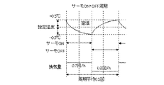
図14は、実施の形態1に係る空気環境調整システム100の運転の一例である。給湯空調システム30は、空調対象室1内の空気の温度を所定の範囲に維持するために、ヒートポンプ装置32の運転及び停止を繰り返す。このとき、給湯空調システム30は、空調対象室1内の空気の温度が設定温度T0よりも0.5℃低いサーモオン温度に達すると、給湯空調システム30はサーモオン制御されて、運転を開始する。つまり、圧縮機46を起動させ、冷凍サイクル回路33に冷媒を循環させることにより、給湯空調システム30は、暖房運転を行う。給湯空調システム30の暖房能力が空調対象室1内の暖房負荷よりも高い場合、空調対象室1内の空気の温度は上昇し、設定温度T0よりも0.5℃高いサーモオフ温度に達すると、給湯空調システム30は、サーモオフ制御されて、運転を停止する。このとき、給湯空調システム30は、圧縮機46を停止し、利用側熱交換器43において冷媒と空気との熱交換を行わない運転状態になる。
(Operation of air environment adjustment system 100 during thermo operation)
FIG. 14 is an example of operation of the air environment conditioning system 100 according to Embodiment 1. FIG. The hot water supply air-conditioning system 30 repeats operation and stop of the heat pump device 32 in order to maintain the temperature of the air in the air-conditioned room 1 within a predetermined range. At this time, when the temperature of the air in the air-conditioned room 1 reaches the thermo-on temperature, which is 0.5° C. lower than the set temperature T0, the hot water supply air-conditioning system 30 is thermo-on controlled and starts operating. That is, the hot water supply air conditioning system 30 performs heating operation by activating the compressor 46 and circulating the refrigerant in the refrigeration cycle circuit 33 . When the heating capacity of the hot water supply air conditioning system 30 is higher than the heating load in the air-conditioned room 1, the temperature of the air in the air-conditioned room 1 rises and reaches the thermo-off temperature, which is 0.5° C. higher than the set temperature T0. The hot water supply air-conditioning system 30 is thermo-off controlled to stop the operation. At this time, the hot water supply air-conditioning system 30 stops the compressor 46 and enters an operating state in which heat exchange between refrigerant and air is not performed in the user-side heat exchanger 43 .

次に、実施の形態1に係る空気環境調整システム100の動作について説明する。以下においては、給湯空調システム30が暖房運転を行う場合について説明する。空調対象室1の温度調節を行う場合、空調対象室1内の暖房負荷に応じて、給湯空調システム30の運転状態が決まる。例えば、空調対象室1内の空気が低温であり、給湯空調システム30に設定された目標温度との差が大きい場合、給湯空調システム30は、圧縮機46の回転数を増加させ、暖房能力が高い状態で運転される。暖房負荷とは、空調対象室1内の空気が有する冷熱、空調対象室1内に居る人等の熱源、又は換気装置20が換気を行うことにより空調対象室1内に流入する冷熱等である。換気装置20は、通常運転においては、0.5回/hの換気量で運転されている。そのため、換気装置20により空調対象室1に導入される空気は、暖房負荷となっている。空調対象室1の暖房負荷が大きい場合、給湯空調システム30は、暖房負荷よりも高い暖房能力で運転され、室温を低下させる。このとき、圧縮機46は高い回転数で運転される。 Next, operation of the air environment adjustment system 100 according to Embodiment 1 will be described. A case where hot water supply and air conditioning system 30 performs heating operation will be described below. When the temperature of the air-conditioned room 1 is adjusted, the operating state of the hot water supply air conditioning system 30 is determined according to the heating load in the air-conditioned room 1 . For example, when the temperature of the air in the room 1 to be air-conditioned is low and there is a large difference from the target temperature set in the hot water supply air conditioning system 30, the hot water supply air conditioning system 30 increases the rotation speed of the compressor 46 to increase the heating capacity. run on high. The heating load is the cold heat of the air in the air-conditioned room 1, the heat source such as people in the air-conditioned room 1, or the cold heat that flows into the air-conditioned room 1 when the ventilation device 20 performs ventilation. . The ventilator 20 is operated at a ventilation rate of 0.5 times/h in normal operation. Therefore, the air introduced into the air-conditioned room 1 by the ventilation device 20 serves as a heating load. When the heating load of the air-conditioned room 1 is large, the hot water supply air-conditioning system 30 is operated with a heating capacity higher than the heating load to lower the room temperature. At this time, the compressor 46 is operated at a high rotational speed.

一方、給湯空調システム30により空調対象室1内の室温が目標温度、即ち給湯空調システム30の設定温度T0に達し、室内の暖房負荷が小さい状態になると、給湯空調システム30は、低能力運転状態で運転される。このとき、給湯空調システム30に必要とされる暖房能力が最低出力以下である場合、給湯空調システム30は、空調対象室1内の空気の温度に応じてサーモオフ制御及びサーモオン制御が行われる、サーモ運転が行われる。 On the other hand, when the room temperature in the room 1 to be air-conditioned by the hot water supply air conditioning system 30 reaches the target temperature, that is, the set temperature T0 of the hot water supply air conditioning system 30, and the indoor heating load becomes small, the hot water supply air conditioning system 30 enters a low capacity operation state. is driven by At this time, if the heating capacity required of the hot water supply air conditioning system 30 is equal to or less than the minimum output, the hot water supply air conditioning system 30 performs thermo off control and thermo on control according to the temperature of the air in the air-conditioned room 1. driving takes place.

図14においては、換気装置20の通常運転の換気量である場合の給湯空調システム30の運転状態と温度の変化が示されている。給湯空調システム30は、空調対象室1内の空気の温度を所定の範囲に維持するために、運転及び停止を繰り返す。実施の形態1においては、空調対象室1の室温が設定温度T0よりも0.5℃低い温度に達すると、給湯空調システム30はサーモオン制御されて、運転を開始する。つまり、圧縮機46を起動させ、冷凍サイクル回路33に冷媒を循環させることにより、給湯空調システム30は、暖房運転を行う。給湯空調システム30の暖房能力が空調対象室1内の暖房負荷よりも高い場合、空調対象室1内の空気の温度は上昇し、設定温度T0よりも0.5℃高い温度に達すると、給湯空調システム30は、サーモオフ制御されて、運転を停止する。このとき、給湯空調システム30は、圧縮機46を停止し、利用側熱交換器43において冷媒と空調装置31側の回路の水との熱交換を行わない運転状態になる。 FIG. 14 shows changes in the operating state and temperature of the hot water supply air conditioning system 30 when the ventilation amount of the ventilation device 20 is normal operation. The hot water supply air-conditioning system 30 repeats operation and stop in order to maintain the temperature of the air in the air-conditioned room 1 within a predetermined range. In Embodiment 1, when the room temperature of the air-conditioned room 1 reaches a temperature lower than the set temperature T0 by 0.5° C., the hot water supply air conditioning system 30 is thermo-on controlled and starts operating. That is, the hot water supply air conditioning system 30 performs heating operation by activating the compressor 46 and circulating the refrigerant in the refrigeration cycle circuit 33 . When the heating capacity of the hot water supply air conditioning system 30 is higher than the heating load in the air-conditioned room 1, the temperature of the air in the air-conditioned room 1 rises, and when it reaches a temperature higher than the set temperature T0 by 0.5° C., the hot water is supplied. The air conditioning system 30 is thermo-off controlled and stops operating. At this time, the hot water supply air-conditioning system 30 stops the compressor 46 and enters an operating state in which the user-side heat exchanger 43 does not exchange heat between the refrigerant and the water in the circuit on the air conditioner 31 side.

上記の様に給湯空調システム30がサーモオン及びサーモオフ制御されている場合においても、換気装置20は、空調対象室1内の換気を行っている。給湯空調システム30がサーモオン及びサーモオフ制御されている場合に、換気装置20が通常運転のまま0.5回/hの換気量で運転されていると、給湯空調システム30は、換気装置20により空調対象室1内に導入される空気による熱により、室温が変動し、サーモオン及びサーモオフ制御を頻繁に繰り返すことになる。従来においては、給湯空調システム30がサーモオン及びサーモオフ制御を繰り返すことにより、給湯空調システム30が備える機器、特に圧縮機46は、発停回数が多くなり、機器寿命が低下するという課題があった。また、給湯空調システム30の発停回数が増加することにより、エネルギー損失も増加するという課題があった。 Even when the hot water supply air-conditioning system 30 is thermo-on and thermo-off controlled as described above, the ventilator 20 ventilates the air-conditioned room 1 . When the hot water supply air-conditioning system 30 is under thermo-on and thermo-off control, if the ventilator 20 is operated at a ventilation rate of 0.5 times/h in normal operation, the hot water supply air-conditioning system 30 is air-conditioned by the ventilator 20. The room temperature fluctuates due to the heat generated by the air introduced into the target room 1, and the thermo-on and thermo-off controls are frequently repeated. Conventionally, the hot water supply air conditioning system 30 repeats thermo-on and thermo off control, and thus the number of starts and stops of the equipment provided in the hot water supply air conditioning system 30, especially the compressor 46, increases, resulting in a reduction in equipment life. Moreover, there is a problem that energy loss increases as the number of times the hot water supply air conditioning system 30 starts and stops increases.

しかし、実施の形態1に係る空気環境調整システム100においては、制御装置10は、給湯空調システム30の運転情報を取得して、給湯空調システム30の運転状態に応じて換気装置20の運転が制御される。 However, in the air environment adjustment system 100 according to Embodiment 1, the control device 10 acquires the operation information of the hot water supply air conditioning system 30 and controls the operation of the ventilation device 20 according to the operation state of the hot water supply air conditioning system 30. be done.

(第3換気モード)
図15は、実施の形態1に係る給湯空調システム30がサーモ運転している時の換気装置20及び給湯空調システム30の運転の一例である。図15においては、制御装置10により、換気装置20の換気量が制御されている場合の給湯空調システム30の運転状態と温度の変化が示されている。制御装置10は、給湯空調システム30がサーモオン制御されている場合に、換気装置20の換気量を0.7回/hに設定する。そして、制御装置10は、給湯空調システム30がサーモオフ制御されている場合は、換気装置20の換気量を0.3回/hに設定する。換気装置20をこのように制御する運転モードを、第3換気モードと称する。第3換気モードは、サーモ運転モードと称される場合がある。
(Third ventilation mode)
FIG. 15 shows an example of operation of ventilator 20 and hot water supply and air conditioning system 30 when hot water supply and air conditioning system 30 according to Embodiment 1 is in thermo operation. FIG. 15 shows changes in the operating state and temperature of hot water supply air conditioning system 30 when control device 10 controls the amount of ventilation of ventilator 20 . The controller 10 sets the ventilation rate of the ventilator 20 to 0.7 times/h when the hot water supply air conditioning system 30 is thermo-on controlled. Then, when the hot water supply air-conditioning system 30 is under thermo-off control, the controller 10 sets the ventilation rate of the ventilator 20 to 0.3 times/h. A mode of operation in which the ventilator 20 is controlled in this manner is referred to as a third ventilation mode. A third ventilation mode is sometimes referred to as a thermo operating mode.

このように構成されることにより、給湯空調システム30がサーモオン制御であるときには、空調対象室1内に導入される外気が通常より多くなる。そのため、給湯空調システム30の暖房運転による空調対象室1の空気の温度変化が緩やかになり、給湯空調システム30は、サーモオン制御で運転される時間が長くなる。一方、給湯空調システム30がサーモオフ制御であるときには、空調対象室1に導入される外気の量が通常より少なくなる。そのため、給湯空調システム30による暖房運転が停止されていても、空調対象室1の空気の温度が維持されやすくなり、温度変化が緩やかになる。これにより、給湯空調システム30のサーモオフ制御の時間が長くなる。つまり、図14で示されたように換気装置20が通常運転である0.5回/hの換気量で運転されている場合と比較して、図15で示されたように制御装置10により換気装置20の運転が制御された場合は、サーモオン及びサーモオフ制御の周期が長くなる。つまり、単位時間当たりの給湯空調システム30の発停回数が少なくなる。 With this configuration, when the hot water supply air-conditioning system 30 is in thermo-on control, more outside air is introduced into the air-conditioned room 1 than usual. Therefore, the temperature change in the air-conditioned room 1 due to the heating operation of the hot water supply air conditioning system 30 becomes moderate, and the hot water supply air conditioning system 30 is operated under thermo-on control for a longer period of time. On the other hand, when the hot water supply air-conditioning system 30 is under thermo-off control, the amount of outside air introduced into the air-conditioned room 1 is smaller than usual. Therefore, even if the heating operation by the hot water supply air-conditioning system 30 is stopped, the temperature of the air in the air-conditioned room 1 is easily maintained, and the temperature change becomes moderate. As a result, the thermo-off control time of the hot water supply air conditioning system 30 is lengthened. In other words, compared to the case where the ventilator 20 is operated at a ventilation rate of 0.5 times/h, which is normal operation, as shown in FIG. When the operation of the ventilator 20 is controlled, the cycle of thermo-on and thermo-off control is lengthened. That is, the number of times the hot water supply air conditioning system 30 is started and stopped per unit time is reduced.

図16は、実施の形態1に係る制御装置10の制御フローの一例である。以上のように構成された空気環境調整システム100の制御装置10において実行される処理の流れについて、図16に示すフローチャートを参照して説明する。 16 is an example of a control flow of the control device 10 according to Embodiment 1. FIG. The flow of processing executed by the controller 10 of the air environment adjustment system 100 configured as described above will be described with reference to the flowchart shown in FIG.

制御開始時において、制御装置10は、室温情報を取得する(ステップD1)。室温情報は、室温検知器11において検知された空調対象室1内の空気の温度又は給湯空調システム30の空調装置31が備える温度センサ等において検知された空気の温度である。室温情報は、室温検知器11及び給湯空調制御端末13の少なくとも一方から制御装置10の通信部53に送信される。通信部53で取得された室温情報は、制御部51において処理され、必要に応じ記憶部52に記憶される。 At the start of control, the control device 10 acquires room temperature information (step D1). The room temperature information is the temperature of the air in the air-conditioned room 1 detected by the room temperature detector 11 or the temperature of the air detected by a temperature sensor or the like included in the air conditioner 31 of the hot water supply air conditioning system 30 . The room temperature information is transmitted from at least one of the room temperature detector 11 and the hot water supply air conditioning control terminal 13 to the communication unit 53 of the control device 10 . The room temperature information acquired by the communication unit 53 is processed by the control unit 51 and stored in the storage unit 52 as necessary.

制御装置10は、運転情報を取得する(ステップD2)。運転情報は、少なくとも給湯空調システム30が備える圧縮機46の周波数である。運転情報は、給湯空調制御端末13から制御装置10の通信部53に送信される。通信部53で取得された運転情報は、制御部51において処理され、必要に応じ記憶部52に記憶される。 The control device 10 acquires driving information (step D2). The operating information is at least the frequency of the compressor 46 included in the hot water supply air conditioning system 30 . The operation information is transmitted from the hot water supply and air conditioning control terminal 13 to the communication unit 53 of the control device 10 . The driving information acquired by the communication unit 53 is processed by the control unit 51 and stored in the storage unit 52 as necessary.

制御装置10は、給湯空調システム30がサーモ運転状態であるか否かを判定する(ステップD3)。制御装置10は、ステップD2において取得された給湯空調システム30の運転情報を基に、給湯空調システム30が通常能力未満で運転されているサーモ運転状態であるか否かを判定する。給湯空調システム30が通常能力で運転されている場合とは、給湯空調システム30が給湯空調システム30の最低出力から最高出力までの間の出力で連続運転されている状態を言う。上述した通常暖房運転は、通常能力での運転に該当する。サーモ運転モードとは、給湯空調システム30がサーモオン制御及びサーモオフ制御を行っている状態を言う。 Control device 10 determines whether or not hot water supply and air conditioning system 30 is in the thermo operation state (step D3). Based on the operation information of the hot water supply air-conditioning system 30 acquired in step D2, the controller 10 determines whether the hot water supply air-conditioning system 30 is in a thermo-operation state in which the water supply air-conditioning system 30 is operated at less than normal capacity. The case where the hot water supply air conditioning system 30 is operated at normal capacity means a state in which the hot water supply air conditioning system 30 is continuously operated at an output between the minimum output and the maximum output of the hot water supply air conditioning system 30 . The normal heating operation described above corresponds to operation at normal capacity. The thermo operating mode is a state in which the hot water supply air conditioning system 30 is performing thermo ON control and thermo OFF control.

給湯空調システム30がサーモ運転モードにあるか否かは、給湯空調システム30の運転情報又は給湯空調システム30の運転情報を記憶して得られた運転履歴情報から判定される。実施の形態1においては、運転履歴情報は圧縮機46の周波数のパターンである。ステップD3における制御装置10の給湯空調システム30がサーモ運転状態にあるか否かの判定については、詳細後述する。 Whether or not the hot water supply air conditioning system 30 is in the thermo operation mode is determined from operation information of the hot water supply air conditioning system 30 or operation history information obtained by storing the operation information of the hot water supply air conditioning system 30 . In Embodiment 1, the driving history information is the frequency pattern of the compressor 46 . The determination of whether or not the hot water supply air conditioning system 30 of the controller 10 is in the thermo operation state in step D3 will be described later in detail.

ステップD3において、給湯空調システム30がサーモ運転を行っていない場合は、換気装置20は、図8及び図9に示された第1換気モードで運転を行い、室温の変動に応じて換気量を増減させて運転される。つまり、ステップD3においてNoの場合は、第3換気モードでの制御を終了する。ステップD3において、給湯空調システム30がサーモ運転状態であると判定された場合は、制御装置10は、給湯空調システム30の運転履歴情報を取得する(ステップD4)。具体的には、記憶部52に記憶された給湯空調システム30の圧縮機46の運転パターンを取得する。 In step D3, if the hot water supply air-conditioning system 30 is not in thermo operation, the ventilator 20 operates in the first ventilation mode shown in FIGS. It is operated by increasing and decreasing. That is, if No in step D3, the control in the third ventilation mode is terminated. When it is determined in step D3 that hot water supply and air conditioning system 30 is in the thermo operating state, control device 10 acquires operation history information of hot water supply and air conditioning system 30 (step D4). Specifically, the operation pattern of the compressor 46 of the hot water supply air conditioning system 30 stored in the storage unit 52 is obtained.

ステップD4が完了した後、制御装置10は、給湯空調システム30のサーモオン制御時及びサーモオフ制御時のそれぞれの場合における換気装置20の換気量を決定する(ステップD5)。 After step D4 is completed, controller 10 determines the ventilation volume of ventilator 20 in each case of thermo-on control and thermo-off control of hot water supply air conditioning system 30 (step D5).

制御装置10は、給湯空調システム30がサーモオン制御時及びサーモオフ制御時のそれぞれにおいて、換気装置20の換気量を制御する。しかし、換気量制御において、換気装置20の換気量が少ない状態が長時間継続すると、空調対象室1に必要な換気量が確保出来なくなる場合がある。実施の形態1においては、空調対象室1に必要な換気量は、0.5回/hとされている。これを通常換気量Q0と称する。つまり、例えば換気装置20の換気量が0.3回/hに設定された場合に、その換気量が長時間継続されると、給湯空調システム30のサーモオン制御及びサーモオフ制御がそれぞれ1回ずつ行われるサーモ運転1周期当たりの換気量が0.5回/hに満たなくなる場合がある。また、換気量制御において、換気装置20の換気量が多い状態が長時間継続すると、換気により空調対象室1の暖房負荷が大きくなり、給湯空調システム30の暖房能力を高くして運転することになり、給湯空調システム30の消費電力が大きくなる。 The controller 10 controls the ventilation volume of the ventilator 20 when the hot water supply and air conditioning system 30 is in thermo-on control and thermo-off control. However, in ventilation volume control, if a state in which the ventilation volume of the ventilator 20 is low continues for a long period of time, the necessary ventilation volume for the air-conditioned room 1 may not be ensured. In Embodiment 1, the ventilation rate required for the air-conditioned room 1 is 0.5 times/h. This is called normal ventilation Q0. That is, for example, when the ventilation rate of the ventilator 20 is set to 0.3 times/h, if the ventilation rate continues for a long time, the hot water supply air conditioning system 30 is thermo-on controlled and thermo-off controlled once. There are cases where the ventilation volume per one cycle of thermo operation is less than 0.5 times/h. In addition, in ventilation volume control, if a state in which the ventilation volume of the ventilation device 20 is high continues for a long time, the heating load of the air-conditioned room 1 increases due to ventilation, and the hot water supply air conditioning system 30 is operated with a high heating capacity. As a result, the power consumption of the hot water supply air conditioning system 30 increases.

以上のような課題を解消するため、実施の形態1に係る制御装置10は、給湯空調システム30の運転履歴情報からサーモオフ制御の継続時間であるサーモオン制御時間Δt1及びサーモオン制御の継続時間であるサーモオフ制御時間Δt2をそれぞれ読み取る。制御装置10は、サーモオン制御時の換気装置20の換気量を通常換気量Q0よりも多く設定し、サーモオフ制御時の換気装置20の換気量を通常換気量Q0よりも少なく設定しつつ、サーモ運転1周期当たりの平均換気量が通常換気量Q0と同等になるように換気量を制御する。 In order to solve the above problems, control device 10 according to Embodiment 1 provides thermo-on control time Δt1, which is the duration of thermo-off control, and thermo-off control duration, which is the duration of thermo-on control, from the operation history information of hot water supply air conditioning system 30. Each control time Δt2 is read. The control device 10 sets the ventilation volume of the ventilator 20 during thermo-on control to be larger than the normal ventilation volume Q0, and sets the ventilation volume of the ventilation device 20 during thermo-off control to be smaller than the normal ventilation volume Q0, while the thermo operation is performed. The ventilation volume is controlled so that the average ventilation volume per cycle is equal to the normal ventilation volume Q0.

図17は、実施の形態1に係る空気環境調整システム100における給湯空調システム30の圧縮機46の運転パターンの一例である。図17に示される様に、給湯空調システム30のサーモ運転のパターンは3種類がある。第1のパターンは、サーモオン制御時間Δt1がサーモオフ制御時間Δt2よりも長い場合である。第2のパターンは、サーモオン制御時間Δt1がサーモオフ制御時間Δt2よりも短い場合である。第3のパターンは、サーモオン制御時間Δt1とサーモオフ制御時間Δt2とが同じ長さである場合である。制御装置10は、例えばサーモオン制御時間Δt1とサーモオフ制御時間Δt2との差が1分以上ある場合に、第1のパターン及び第2のパターンに該当するという判断を行うと良い。その場合、制御装置10は、サーモオン制御時間Δt1とサーモオフ制御時間Δt2との差が1分以内である場合に、第3のパターンに該当すると判断する。このように構成されることにより、制御装置10は、サーモ運転のパターンを明確に判断できる。それぞれのパターンにおいて、制御装置10がどのように換気装置20の換気量を設定するかについては、詳細後述する。 FIG. 17 shows an example of the operation pattern of the compressor 46 of the hot water supply air conditioning system 30 in the air environment adjustment system 100 according to Embodiment 1. As shown in FIG. As shown in FIG. 17, there are three types of thermo-operation patterns of the hot water supply air conditioning system 30 . The first pattern is when the thermo-on control time Δt1 is longer than the thermo-off control time Δt2. The second pattern is when the thermo-on control time Δt1 is shorter than the thermo-off control time Δt2. A third pattern is when the thermo-on control time Δt1 and the thermo-off control time Δt2 are the same length. For example, when the difference between the thermo-on control time Δt1 and the thermo-off control time Δt2 is 1 minute or more, the control device 10 may determine that the first pattern and the second pattern are applicable. In this case, the control device 10 determines that the third pattern applies when the difference between the thermo-on control time Δt1 and the thermo-off control time Δt2 is within 1 minute. With such a configuration, the control device 10 can clearly determine the pattern of thermo-operation. How the control device 10 sets the ventilation volume of the ventilation device 20 in each pattern will be described later in detail.

図16に戻り、ステップD5が完了した後、制御装置10は、サーモオン制御時間Δt1及びサーモオフ制御時間Δt2のそれぞれにおける換気量を、例えば記憶部52に格納する。そして、制御装置10は、運転情報から給湯空調システム30がサーモオン制御又はサーモオフ制御で運転されていることを判断し、その運転状態に応じた換気量を換気制御端末12に送信する。換気制御端末12は、制御装置10からの指示に基づき換気装置20を制御する(ステップD6)。 Returning to FIG. 16, after step D5 is completed, the control device 10 stores the ventilation volume for each of the thermo-on control time Δt1 and the thermo-off control time Δt2 in the storage unit 52, for example. Then, the control device 10 determines from the operation information that the hot water supply and air conditioning system 30 is operated under the thermo-on control or the thermo-off control, and transmits the ventilation amount according to the operating state to the ventilation control terminal 12 . The ventilation control terminal 12 controls the ventilation device 20 based on the instruction from the control device 10 (step D6).

図16に示される制御装置10の制御フローは、空気環境調整システム100の給湯空調システム30が稼働している間において給湯運転、除霜運転、及び通常暖房運転でない場合は、所定の頻度で開始から終了までを繰り返す。ただし、例えば、ユーザーが図16に示された制御をしないように設定した場合、又は空調対象室1の暖房負荷が高くなり給湯空調システム30が所定の暖房能力で運転を継続している場合等には、制御を終了し、制御フローの繰り返しを停止させても良い。 The control flow of the control device 10 shown in FIG. 16 is started at a predetermined frequency if the hot water supply operation, defrosting operation, or normal heating operation is not performed while the hot water supply air conditioning system 30 of the air environment adjustment system 100 is in operation. Repeat from to end. However, for example, when the user sets not to perform the control shown in FIG. 16, or when the heating load of the air-conditioned room 1 increases and the hot water supply air-conditioning system 30 continues to operate at a predetermined heating capacity. Alternatively, the control may end and stop repeating the control flow.

(給湯空調システム30のサーモ運転状態の判定について)
図18は、実施の形態1に係る空気環境調整システム100の給湯空調システム30の運転履歴情報の一例を示している。図18に基づき、図16のステップD3の判定について説明する。図18は、給湯空調システム30の圧縮機46の周波数の時間的な推移を示した図である。空調対象室1を暖房する場合において、給湯空調システム30の運転を開始した直後は、空調対象室1内の空気の温度が目標とする設定温度T0よりも高いため、給湯空調システム30は、暖房能力を最大にして運転される。このとき圧縮機46の周波数は最大値で運転される。空調対象室1の温度が低下し設定温度T0に近づくと、圧縮機46の周波数は段階的に低くなり、圧縮機46の運転周波数の最小値で運転される。圧縮機46の運転周波数の最小値で運転されているときに、室温が設定温度T0から所定温度低い温度に達すると、圧縮機46は運転を停止する。それ以降、空調対象室1の暖房負荷に大きな変動が無ければ、給湯空調システム30は、圧縮機46の発停を繰り返す、サーモ運転を行う。
(Regarding determination of thermo operation state of hot water supply air conditioning system 30)
FIG. 18 shows an example of operation history information of the hot water supply air conditioning system 30 of the air environment adjustment system 100 according to the first embodiment. Based on FIG. 18, the determination of step D3 in FIG. 16 will be described. FIG. 18 is a diagram showing the temporal transition of the frequency of compressor 46 of hot water supply air conditioning system 30. As shown in FIG. In the case of heating the air-conditioned room 1, the temperature of the air in the air-conditioned room 1 is higher than the target set temperature T0 immediately after the operation of the hot water supply air conditioning system 30 is started. Operated at maximum capacity. At this time, the frequency of the compressor 46 is operated at its maximum value. When the temperature of the air-conditioned room 1 decreases and approaches the set temperature T0, the frequency of the compressor 46 is lowered step by step, and the compressor 46 is operated at the minimum operating frequency. When the room temperature reaches a predetermined temperature lower than the set temperature T0 while the compressor 46 is operating at the minimum operating frequency, the compressor 46 stops operating. After that, if the heating load of the air-conditioned room 1 does not change significantly, the hot water supply air-conditioning system 30 repeats starting and stopping of the compressor 46 to perform thermo-operation.

制御装置10が、給湯空調システム30のサーモ運転状態を判定する手段としては、例えば以下の3つがある。第1の手段においては、制御装置10が、給湯空調システム30の圧縮機46の周波数が最小値になっていることを検知しかつ室温が設定温度T0±x℃の範囲にある場合に、給湯空調システム30がサーモ運転状態であると判定する。このとき、制御装置10は、給湯空調制御端末13から空調対象室1の目標温度である設定温度T0と、圧縮機46の周波数の情報を運転情報として取得する。また、制御装置10は、室温検知器11から室温情報を取得する。室温検知器11からの室温情報が、給湯空調制御端末13からの設定温度T0に対し±x℃の範囲内にある場合に、制御装置10は、室温が設定温度T0±x℃の範囲にあると判断する。なお、室温情報は、給湯空調制御端末13から室内機の温度センサ等の温度を取得して代用することもできる。 There are, for example, the following three means for the controller 10 to determine the thermo operating state of the hot water supply air conditioning system 30 . In the first means, when the control device 10 detects that the frequency of the compressor 46 of the hot water supply air conditioning system 30 is the minimum value and the room temperature is within the range of the set temperature T0±x° C., the hot water supply It is determined that the air conditioning system 30 is in the thermo operating state. At this time, the control device 10 acquires the set temperature T0, which is the target temperature of the air-conditioned room 1, and information on the frequency of the compressor 46 from the hot water supply air conditioning control terminal 13 as operation information. Also, the control device 10 acquires room temperature information from the room temperature detector 11 . When the room temperature information from the room temperature detector 11 is within the range of ±x°C with respect to the set temperature T0 from the hot water supply air conditioning control terminal 13, the controller 10 determines that the room temperature is within the range of the set temperature T0 ±x°C. I judge. It should be noted that the room temperature information can be substituted by obtaining the temperature of the temperature sensor of the indoor unit from the hot water supply air conditioning control terminal 13 .

第2の手段においては、制御装置10が給湯空調システム30の圧縮機46の周波数が0になっていることを検知したときに、給湯空調システム30がサーモ運転状態であると判定する。このとき、制御装置10は、給湯空調制御端末13から圧縮機46の周波数の情報を運転情報として取得し、給湯空調システム30が運転状態でありながら圧縮機46が停止している場合に、サーモ運転状態であると判断する。なお、第2の手段においては、制御装置10は、室温情報及び設定温度T0の情報を利用していないが、室温情報及び設定温度T0の情報から室温が設定温度T0±x℃の範囲にあるか否かの判断を同時に行うことにより、判定の精度が向上する。 In the second means, when controller 10 detects that the frequency of compressor 46 of hot water supply air conditioning system 30 is 0, hot water supply air conditioning system 30 is determined to be in the thermo operating state. At this time, the control device 10 acquires information on the frequency of the compressor 46 from the hot water supply air conditioning control terminal 13 as operation information, and when the hot water supply air conditioning system 30 is in operation and the compressor 46 is stopped, the thermostat is turned on. It is determined that the vehicle is in operation. In the second means, the control device 10 does not use the room temperature information and the set temperature T0 information, but the room temperature is within the range of the set temperature T0±x° C. based on the room temperature information and the set temperature T0 information. By simultaneously determining whether or not, the accuracy of the determination is improved.

第3の手段においては、制御装置10が、給湯空調システム30の圧縮機46の運転履歴情報を取得し、圧縮機46の周波数パターンから、圧縮機46の停止及び起動が少なくとも1回以上行われた場合に給湯空調システム30がサーモ運転であると判定する。このとき、制御装置10は、記憶部52に記憶されている周波数パターンを取得し、現時点から過去の所定の時間内において圧縮機46の停止及び起動が少なくとも1回行われた場合にサーモ運転状態であると判断する。なお、第3の手段においても、第1の手段及び第2の手段と同様に、室温情報を利用することにより判定の精度が向上する。 In the third means, the control device 10 acquires the operation history information of the compressor 46 of the hot water supply air conditioning system 30, and based on the frequency pattern of the compressor 46, stops and starts the compressor 46 at least once. If so, it is determined that the hot water supply air conditioning system 30 is in thermo operation. At this time, the control device 10 acquires the frequency pattern stored in the storage unit 52, and determines whether the compressor 46 has been stopped and started at least once within a predetermined time period from the present time to the thermo operating state. We judge that it is. Also in the third means, the accuracy of determination is improved by using the room temperature information, as in the first and second means.

(制御装置10による換気装置20の換気量の設定について)
図16のステップD5における、制御装置10による換気装置20の換気量設定について説明する。まず、図17に示されている、第1のパターンにおける制御装置10の換気量制御について説明する。第1のパターンにおいては、サーモオン制御時間Δt1がサーモオフ制御時間Δt2よりも長い。まず、制御装置10は、サーモオフ制御時間Δt2における第1換気量Q1を決定する。第1換気量Q1は、給湯空調システム30が通常能力で運転されているときの通常換気量Q0よりも減少させたサーモオフ時換気量に設定され、実施の形態1においては0.3回/hとしている。そして、制御装置10は、第1換気量Q1とサーモオフ制御時間Δt2とからサーモオン制御に入るまでの第1積算換気量V1を算出する。サーモオン制御時間Δt1は、運転履歴情報から既知である。サーモ運転1周期当たりにおいて平均換気量が通常換気量Q0である0.5回/hとなるようなサーモオン制御時間Δt1における換気量Qは、以下の方程式から求められる。
Q×Δt1+Q1×Δt2=Q0×(Δt1+Δt2)・・・(式1)
(Regarding the setting of the ventilation volume of the ventilation device 20 by the control device 10)
The ventilation volume setting of the ventilator 20 by the control device 10 in step D5 of FIG. 16 will be described. First, ventilation volume control by the control device 10 in the first pattern shown in FIG. 17 will be described. In the first pattern, the thermo-on control time Δt1 is longer than the thermo-off control time Δt2. First, the control device 10 determines the first ventilation volume Q1 during the thermo-off control time Δt2. The first ventilation volume Q1 is set to the thermo-off ventilation volume that is lower than the normal ventilation volume Q0 when the hot water supply air conditioning system 30 is operated at normal capacity, and is 0.3 times/h in the first embodiment. and Then, the control device 10 calculates a first integrated ventilation volume V1 from the first ventilation volume Q1 and the thermo-off control time Δt2 until the thermo-on control is started. The thermo-on control time Δt1 is known from the driving history information. The ventilation volume Q at the thermo-on control time Δt1 such that the average ventilation volume is 0.5 times/h, which is the normal ventilation volume Q0, per cycle of thermo operation is obtained from the following equation.
Q×Δt1+Q1×Δt2=Q0×(Δt1+Δt2) (Formula 1)

図17に示されている第2のパターンにおける制御装置10の換気量制御について説明する。第2のパターンにおいては、サーモオン制御時間Δt1がサーモオフ制御時間Δt2よりも短い。まず、制御装置10は、サーモオン制御時間Δt1における第2換気量Q2を決定する。第2換気量Q2は、給湯空調システム30が通常能力で運転されているときの通常換気量Q0よりも増加させたサーモオン時換気量に設定され、実施の形態1においては0.7回/hとしている。そして、制御装置10は、第2換気量Q2とサーモオン制御時間Δt1とからサーモオフ制御に入るまでの第2積算換気量V2を算出する。サーモオフ制御時間Δt2は、運転履歴情報から既知である。サーモ運転1周期当たりにおいて平均換気量が通常換気量Q0となるようなサーモオフ制御時間Δt2における換気量Qは、以下の方程式から求められる。
Q2×Δt1+Q×Δt2=Q0×(Δt1+Δt2)・・・(式2)
The ventilation volume control of the control device 10 in the second pattern shown in FIG. 17 will be described. In the second pattern, the thermo-on control time Δt1 is shorter than the thermo-off control time Δt2. First, the control device 10 determines the second ventilation volume Q2 during the thermo-on control time Δt1. The second ventilation volume Q2 is set to a thermo-on ventilation volume that is greater than the normal ventilation volume Q0 when the hot water supply air-conditioning system 30 is operated at normal capacity. and Then, the control device 10 calculates a second cumulative ventilation volume V2 from the second ventilation volume Q2 and the thermo-on control time Δt1 until the thermo-off control is started. The thermo-off control time Δt2 is known from the driving history information. The ventilation volume Q at the thermo off control time Δt2 such that the average ventilation volume becomes the normal ventilation volume Q0 in one cycle of thermo operation is obtained from the following equation.
Q2×Δt1+Q×Δt2=Q0×(Δt1+Δt2) (Formula 2)

なお、第1のパターン及び第2のパターンにおける第1換気量Q1及び第2換気量Q2は、予め設定された換気量である。実施の形態1においては、Q1=0.3回/h、Q2=0.7回/hに設定されているが、これは一例であり、給湯空調システム30の暖房性能、空調対象室1の断熱性能等の条件に応じて適宜変更することができる。ただし、第1換気量Q1は、通常換気量Q0よりも低いサーモオフ時換気量であり、第2換気量Q2は、通常換気量Qよりも多いサーモオン時換気量である。つまり、第1換気量Q1は、0≦Q1<0.5回/hに設定される。第2換気量Q2は、0.5<Q2≦1回/hに設定される。また、サーモオン制御時間Δt1は、第1期間と称される場合があり、サーモオフ制御時間Δt2は、第2期間と称される場合がある。 The first ventilation volume Q1 and the second ventilation volume Q2 in the first pattern and the second pattern are preset ventilation volumes. In Embodiment 1, Q1=0.3 times/h and Q2=0.7 times/h are set, but this is an example, and the heating performance of the hot water supply air conditioning system 30 and the air conditioning target room 1 It can be changed as appropriate according to conditions such as heat insulation performance. However, the first ventilation Q1 is a ventilation with the thermostat off that is lower than the normal ventilation Q0, and the second ventilation Q2 is a ventilation with the thermostat on that is larger than the normal ventilation Q0. That is, the first ventilation Q1 is set to 0≦Q1<0.5 times/h. The second ventilation Q2 is set to 0.5<Q2≤1 breath/h. Also, the thermo-on control time Δt1 may be referred to as a first period, and the thermo-off control time Δt2 may be referred to as a second period.

図17に示されている第3のパターンにおける制御装置10の換気量制御について説明する。第3のパターンにおいては、サーモオン制御時間Δt1とサーモオフ制御時間Δt2とが同じ長さである。実際には、制御装置10は、サーモオン制御時間Δt1とサーモオフ制御時間Δt2との長さの差が、例えば1分以内である場合に同じ長さであるとして扱う。 The ventilation volume control of the control device 10 in the third pattern shown in FIG. 17 will be described. In the third pattern, the thermo-on control time Δt1 and the thermo-off control time Δt2 are the same length. In practice, the controller 10 treats the thermo-on control time Δt1 and the thermo-off control time Δt2 as having the same length if the difference is within one minute, for example.

第3のパターンにおいては、制御装置10は、給湯空調制御端末13から取得したサーモオン制御及びサーモオフ制御の閾値設定に基づき、サーモオフ制御時間Δt2における第1換気量Q1を設定する。なお、サーモオン制御及びサーモオフ制御の閾値は、制御装置10が室温検知器11から取得し記憶部52に記憶させた室温情報の履歴に基づいて求めても良い。このとき制御装置10は、給湯空調システム30の運転履歴情報も併せて参照すると良い。 In the third pattern, the control device 10 sets the first ventilation amount Q1 during the thermo-off control time Δt2 based on the threshold settings for thermo-on control and thermo-off control acquired from the hot water supply air conditioning control terminal 13 . Note that the thresholds for thermo-on control and thermo-off control may be obtained based on the history of room temperature information acquired by the control device 10 from the room temperature detector 11 and stored in the storage unit 52 . At this time, the controller 10 may also refer to the operation history information of the hot water supply air conditioning system 30 .

図19は、図17の第3のパターンにおける換気装置20の換気量と給湯空調システム30のサーモ運転切り替えの閾値との相関を示す図である。制御装置10は、給湯空調システム30のサーモ運転切り替えの閾値に応じてサーモオフ制御時間Δt2における第1換気量Q1を変更する。具体的には、図19に示される様に給湯空調システム30のサーモ運転切り替えの閾値の幅が設定温度T0±0.5℃未満の場合は、第1換気量Q1を0.1回/hに設定する。また、閾値の幅が設定温度T0±0.5℃以上±1.0℃未満の場合は、第1換気量Q1を0.2回/hに設定する。以降、制御装置10は、給湯空調システム30の閾値の幅が±0.5℃大きくなる毎に、第1換気量Q1を0.1回/h刻みで大きくなるように設定する。ただし、閾値の幅と第1換気量Q1の増加量との関係は、図10に示すもののみに限定されるものではなく、例えば、閾値の幅と第1換気量Q1との関係を比例させるようにしても良い。 FIG. 19 is a diagram showing the correlation between the ventilation amount of the ventilator 20 and the threshold value for switching to the thermo mode of the hot water supply air conditioning system 30 in the third pattern of FIG. The control device 10 changes the first ventilation amount Q1 during the thermo-off control time Δt2 according to the threshold value for switching the hot water supply and air conditioning system 30 to the thermo mode. Specifically, as shown in FIG. 19, when the range of the threshold value for switching the thermo operation of the hot water supply air conditioning system 30 is less than the set temperature T0±0.5° C., the first ventilation amount Q1 is set to 0.1 times/h. set to When the width of the threshold is equal to or greater than the set temperature T0±0.5° C. and less than ±1.0° C., the first ventilation Q1 is set to 0.2 times/h. After that, the control device 10 sets the first ventilation amount Q1 to increase by 0.1 times/h each time the width of the threshold value of the hot water supply air conditioning system 30 increases by ±0.5°C. However, the relationship between the threshold width and the increase in the first ventilation Q1 is not limited to that shown in FIG. 10. For example, the relationship between the threshold width and the first ventilation Q1 is proportional. You can do it.

第3のパターンにおける換気装置20の換気量の設定は、まず、制御装置10が、給湯空調システム30のサーモオフ制御時間Δt2における第1換気量Q1を図19に基づいて決定する。実施の形態1においては、図15等に示される様に給湯空調システム30のサーモ運転切り替え閾値が設定温度T0±0.5℃であるため、ここでは第1換気量Q1を0.2回/hに設定される。そして、制御装置10は、第1換気量Q1とサーモオフ制御時間Δt2とからサーモオン制御に入るまでの第1積算換気量V1を算出する。サーモオン制御時間Δt1は、運転履歴情報から既知である。サーモ運転1周期当たりにおいて平均換気量が通常換気量Q0となるようなサーモオン制御時間Δt1における換気量Qは、上記の式1から求められる。 In setting the ventilation volume of the ventilator 20 in the third pattern, the control device 10 first determines the first ventilation volume Q1 during the thermo-off control time Δt2 of the hot water supply air conditioning system 30 based on FIG. In Embodiment 1, as shown in FIG. 15 and the like, the thermo-operation switching threshold of the hot water supply air conditioning system 30 is the set temperature T0±0.5° C., so here the first ventilation amount Q1 is set to 0.2 times/ set to h. Then, the control device 10 calculates the first integrated ventilation volume V1 until thermo-on control is started from the first ventilation volume Q1 and the thermo-off control time Δt2. The thermo-on control time Δt1 is known from the driving history information. The ventilation volume Q at the thermo-on control time Δt1 such that the average ventilation volume is equal to the normal ventilation volume Q0 in one cycle of thermo operation is obtained from Equation 1 above.

また、図16に示されている制御装置10の制御フローを繰り返し行う場合は、直近の運転履歴に基づいて上記の換気装置20の換気量の設定を行うと良い。上記の換気量の設定により、サーモオン制御時とサーモオフ制御時とのそれぞれの場合における換気量が変更されるが、換気量の変更に伴いサーモオン制御時間Δt1及びサーモオフ制御時間Δt2の長さがそれぞれ変動する場合があり、上記の第1のパターン、第2のパターン、及び第3のパターンの何れかから他のパターンに変わる場合があり得る。従って、図16に示されている制御装置10の制御フローを繰り返し行い、更新された運転履歴により換気装置20の換気量を変更することにより、空調対象室1の平均換気量がより適正に保たれ、かつ室温の頻繁な変動をより抑えることができる。また、空調対象室1内の負荷が変動した場合であっても、制御フローを繰り返すことにより対応が可能となる。 Further, when the control flow of the control device 10 shown in FIG. 16 is repeatedly performed, it is preferable to set the ventilation volume of the ventilator 20 based on the most recent operation history. By setting the ventilation volume described above, the ventilation volume in each case of thermo-on control and thermo-off control is changed. Any of the first, second, and third patterns described above may change to other patterns. Therefore, by repeatedly performing the control flow of the control device 10 shown in FIG. 16 and changing the ventilation volume of the ventilation device 20 according to the updated operation history, the average ventilation volume of the air-conditioned room 1 can be maintained more appropriately. Dripping and frequent fluctuations in room temperature can be suppressed. Further, even when the load in the air-conditioned room 1 fluctuates, it is possible to cope with it by repeating the control flow.

以上に説明した制御により、制御装置10及び空気環境調整システム100は、空調対象室1の換気による負荷と室温変動とのバランスをとり、室温変動を抑え、給湯空調システム30の圧縮機46の発停回数を低減させることができる。また、換気装置20は、給湯空調システム30のサーモオン制御時及びサーモオフ制御時のそれぞれにおいて異なる換気量に設定して運転される。しかし、換気装置20は、給湯空調システム30のサーモ運転の一周期における平均換気量を通常換気量Q0と同等に確保するように設定されるため、空調対象室1の必要な換気量を確保することができる。また、制御装置10及び空気環境調整システム100によれば、空調対象室1の室温変動が緩やかになるため、空調対象室1の快適性も向上させることができる。 With the control described above, the control device 10 and the air environment adjustment system 100 balance the load due to the ventilation of the air-conditioned room 1 and room temperature fluctuations, suppress the room temperature fluctuations, and control the compressor 46 of the hot water supply air conditioning system 30. The number of stops can be reduced. In addition, the ventilator 20 is operated with different ventilation volumes set during the thermo-on control and during the thermo-off control of the hot water supply air conditioning system 30 . However, since the ventilator 20 is set to ensure the average ventilation volume in one cycle of the thermo operation of the hot water supply air conditioning system 30 to be equivalent to the normal ventilation volume Q0, the required ventilation volume of the air-conditioned room 1 is secured. be able to. In addition, according to the control device 10 and the air environment adjustment system 100, the room temperature fluctuation in the air-conditioned room 1 is moderated, so that the comfort of the air-conditioned room 1 can be improved.

また、以上の説明においては、給湯空調システム30が空調対象室1の暖房を行う場合について説明したが、給湯空調システム30が冷房運転する場合においても同様な制御を行うことができる。冷房運転の場合は、給湯空調システム30の給湯運転時、サーモオフ制御時には、換気により空調対象室1の室温が徐々に上昇し、サーモオン制御時には、給湯空調システム30の冷房能力が空調対象室1の冷房負荷を上回るため、温度が徐々に低下することになる。 In the above description, the case where the hot water supply air conditioning system 30 heats the air-conditioned room 1 has been described, but the same control can be performed when the hot water supply air conditioning system 30 performs the cooling operation. In the case of cooling operation, during the hot water supply operation of the hot water supply air conditioning system 30, during thermo-off control, the room temperature of the air-conditioned room 1 gradually rises due to ventilation, and during thermo-on control, the cooling capacity of the hot water supply air conditioning system 30 increases the cooling capacity of the air-conditioned room 1. Since the cooling load is exceeded, the temperature will gradually drop.

また、上記実施の形態では、制御装置10は、CPUがROM又は記憶部52に記憶されたプログラムを実行することによって、制御部51、通信部53、給湯空調システム運転状態検知部54、室温検知部55、換気制御部57、及び給湯空調制御部58のそれぞれとして機能する。しかし、制御装置10は、専用のハードウェアであってもよい。専用のハードウェアとは、例えば単一回路、複合回路、プログラム化されたプロセッサ、ASIC(Application Specific Integrated Circuit)、FPGA(Field-Programmable Gate Array)、これらの組み合わせ等である。制御装置10が専用のハードウェアである場合、各部の機能それぞれを個別のハードウェアで実現してもよいし、各部の機能をまとめて単一のハードウェアで実現してもよい。 Further, in the above-described embodiment, the control device 10 includes the control unit 51, the communication unit 53, the hot water supply air conditioning system operating state detection unit 54, the room temperature detection, and the like by the CPU executing a program stored in the ROM or the storage unit 52. It functions as each of the unit 55 , the ventilation control unit 57 , and the hot water supply air conditioning control unit 58 . However, the control device 10 may be dedicated hardware. Dedicated hardware includes, for example, single circuits, composite circuits, programmed processors, ASICs (Application Specific Integrated Circuits), FPGAs (Field-Programmable Gate Arrays), combinations thereof, and the like. When the control device 10 is dedicated hardware, each function of each unit may be realized by separate hardware, or the functions of each unit may be collectively realized by a single piece of hardware.

また、各部の機能のうち、一部を専用のハードウェアによって実現し、他の一部をソフトウェア又はファームウェアによって実現してもよい。このように、制御装置10は、ハードウェア、ソフトウェア、ファームウェア、又はこれらの組み合わせによって、上述の各機能を実現することができる。 Also, some of the functions of each unit may be realized by dedicated hardware, and other parts may be realized by software or firmware. Thus, the control device 10 can implement each of the functions described above by hardware, software, firmware, or a combination thereof.

制御装置10の動作を規定する動作プログラムを既存のパーソナルコンピュータ又は情報端末装置等のコンピュータに適用することで、当該コンピュータを、制御装置10として機能させることも可能である。例えば、図1及び図2に示される外部端末90を制御装置10として機能させることもできる。 By applying an operation program that defines the operation of the control device 10 to an existing computer such as a personal computer or an information terminal device, the computer can be made to function as the control device 10 . For example, the external terminal 90 shown in FIGS. 1 and 2 can function as the control device 10. FIG.

制御装置10の動作を規定するプログラムの配布方法は任意であり、例えば、CD-ROM(Compact Disk ROM)、DVD(Digital Versatile Disk)、MO(Magneto Optical Disk)、メモリカード等のコンピュータ読み取り可能な記録媒体に格納して配布してもよいし、インターネット等の通信ネットワークを介して配布してもよい。 Any method of distributing the program that defines the operation of the control device 10 can be used. It may be stored in a recording medium and distributed, or may be distributed via a communication network such as the Internet.

1 空調対象室、10 制御装置、11 室温検知器、12 換気制御端末、13 給湯空調制御端末、20 換気装置、21 吸気パイプ、21a 吸入口、22 排気パイプ、22a 排気口、23 全熱交換部、24 外気直接導入バイパス、25 吸気ファン、26 排気ファン、27 バイパスファン、29 接続部、29a 開閉部、30 給湯空調システム、31 空調装置、32 ヒートポンプ装置、33 冷凍サイクル回路、40 給湯装置、41 給湯端末、42 四方弁、43 利用側熱交換器、44 膨張装置、45 熱源側熱交換器、46 圧縮機、47 流路切替装置、49 室外送風機、51 制御部、52 記憶部、53 通信部、54 給湯空調システム運転状態検知部、55 室温検知部、56 計時部、57 換気制御部、58 給湯空調制御部、60 タンク、62 暖房循環ポンプ、63 給湯ポンプ、90 外部端末、100 空気環境調整システム、Q 換気量、Q0 通常換気量、Q1 第1換気量、Q2 第2換気量、T0 設定温度、T1 温度閾値、T2 温度閾値、V1 第1積算換気量、V2 第2積算換気量、Δt1 サーモオン制御時間、Δt2 サーモオフ制御時間。 1 air conditioning target room 10 control device 11 room temperature detector 12 ventilation control terminal 13 hot water supply air conditioning control terminal 20 ventilator 21 intake pipe 21a intake port 22 exhaust pipe 22a exhaust port 23 total heat exchange unit , 24 Outside air direct introduction bypass 25 Intake fan 26 Exhaust fan 27 Bypass fan 29 Connection part 29a Switching part 30 Hot water supply air conditioning system 31 Air conditioner 32 Heat pump device 33 Refrigeration cycle circuit 40 Hot water heater 41 Hot water supply terminal 42 Four-way valve 43 Use side heat exchanger 44 Expansion device 45 Heat source side heat exchanger 46 Compressor 47 Flow path switching device 49 Outdoor fan 51 Control unit 52 Storage unit 53 Communication unit , 54 hot water supply and air conditioning system operation state detection unit, 55 room temperature detection unit, 56 timing unit, 57 ventilation control unit, 58 hot water supply and air conditioning control unit, 60 tank, 62 heating circulation pump, 63 hot water supply pump, 90 external terminal, 100 air environment adjustment System, Q ventilation volume, Q0 normal ventilation volume, Q1 first ventilation volume, Q2 second ventilation volume, T0 set temperature, T1 temperature threshold, T2 temperature threshold, V1 first cumulative ventilation volume, V2 second cumulative ventilation volume, Δt1 Thermo ON control time, Δt2 Thermo OFF control time.

Claims (28)

給湯装置又は空調装置に熱を供給するヒートポンプを備える給湯空調システムの前記空調装置により室温が設定温度に調整される空調対象室内の空気を換気する換気装置の運転を制御する制御装置であって、
前記給湯空調システムの運転情報及び前記室温を取得する通信部と、
前記換気装置の換気量を制御する換気制御部と、を備え、
前記運転情報は、
前記給湯装置に前記ヒートポンプから熱が供給されている給湯運転、前記空調装置に前記ヒートポンプから熱が供給されている運転のうち、前記給湯空調システムが何れかの状態であるかの情報を含み、
前記換気制御部は、
前記通信部が取得した前記運転情報と前記室温とを取得し、前記運転情報と前記室温とに応じて前記換気量を変動させる、制御装置。
A control device for controlling the operation of a ventilation device for ventilating air in an air-conditioned room in which the room temperature is adjusted to a set temperature by the air conditioner of a hot water supply air conditioning system including a heat pump that supplies heat to the hot water supply device or the air conditioner,
a communication unit that acquires operation information of the hot water supply and air conditioning system and the room temperature;
and a ventilation control unit that controls the ventilation volume of the ventilation device,
The driving information includes:
including information as to whether the hot water supply air conditioning system is in one of a hot water supply operation in which heat is supplied from the heat pump to the water heater and an operation in which heat is supplied to the air conditioner from the heat pump;
The ventilation control unit
A control device that acquires the operating information and the room temperature acquired by the communication unit, and changes the ventilation volume according to the operating information and the room temperature.
前記運転情報において前記給湯空調システムが前記給湯運転である場合に、
前記換気制御部は、
前記室温を取得し、
前記室温が所定の温度閾値に達したときに、前記換気量を通常換気量よりも減少させる、請求項1に記載の制御装置。
When the hot water supply air conditioning system is in the hot water supply operation in the operation information,
The ventilation control unit
obtaining said room temperature;
2. The controller of claim 1 , wherein the ventilation is reduced below normal ventilation when the room temperature reaches a predetermined temperature threshold.
前記給湯空調システムは、
前記ヒートポンプにより沸き上げた湯を貯留するタンクを備え、
前記ヒートポンプにより沸き上げた湯を回路に循環させて前記室温を調整する第1空調回路と、
前記タンクに貯留された前記湯を循環させて前記室温を調整する第2空調回路と、を備え、
前記ヒートポンプが除霜運転中である場合に、前記第2空調回路に切り替えて前記室温を調整するものであって、
前記運転情報は、
前記ヒートポンプが除霜運転中であり、前記タンクの蓄熱量が所定量以上である第1の場合と、
前記ヒートポンプが除霜運転中であり、前記タンクの蓄熱量が所定量よりも低い第2の場合と、のうち、前記給湯空調システムが何れの状態であるかの情報をさらに含み、
前記換気制御部は、
前記通信部が取得した前記運転情報を取得し、前記運転情報において前記給湯空調システムが前記第1の場合であるときに、
前記室温を取得し、
前記室温が前記設定温度よりも低い所定の温度閾値に達したときに、前記換気量を通常換気量よりも減少させるように変更する、請求項1に記載の制御装置。
The hot water supply air conditioning system includes:
Equipped with a tank for storing hot water boiled by the heat pump,
a first air conditioning circuit that adjusts the room temperature by circulating hot water boiled by the heat pump through the circuit;
a second air conditioning circuit for circulating the hot water stored in the tank to adjust the room temperature;
When the heat pump is in defrosting operation , the room temperature is adjusted by switching to the second air conditioning circuit,
The driving information includes:
a first case in which the heat pump is in defrosting operation and the amount of heat stored in the tank is equal to or greater than a predetermined amount;
the heat pump is in defrosting operation and the amount of heat stored in the tank is lower than a predetermined amount, further including information indicating which state the hot water supply air conditioning system is in;
The ventilation control unit
When the operation information acquired by the communication unit is acquired, and the hot water supply and air conditioning system is in the first case in the operation information,
obtaining said room temperature;
2. The control device according to claim 1 , wherein when said room temperature reaches a predetermined temperature threshold lower than said set temperature, said ventilation volume is changed to be lower than normal ventilation volume.
前記温度閾値は、複数の温度閾値から構成され、
前記換気制御部は、
前記複数の温度閾値のうち前記設定温度から離れた前記温度閾値ほど前記換気量を減少させ、前記複数の温度閾値のうち最も前記設定温度から離れた限界温度閾値に達したときに前記換気装置を停止させる、請求項2又は3に記載の制御装置。
The temperature threshold is composed of a plurality of temperature thresholds,
The ventilation control unit
The ventilator is turned on when a limit temperature threshold farthest from the set temperature among the plurality of temperature thresholds is reached, and the ventilator is turned on when the temperature threshold farthest from the set temperature among the plurality of temperature thresholds is reached. 4. The control device according to claim 2 or 3, for stopping.
前記給湯空調システムを制御する給湯空調制御部を更に備え、
前記温度閾値は、複数の温度閾値から構成され、
前記給湯空調制御部は、
前記複数の温度閾値のうち最も前記設定温度から離れた限界温度閾値に達したときに前記第2空調回路に設けられた前記湯を循環させるポンプの出力を増加させ、
前記タンクに貯留された熱量から前記除霜運転の終了時の前記タンク内の前記湯の低下を予測し、前記タンク内の前記湯が前記室温の前記設定温度以上になるように前記ポンプの出力を設定する、請求項3に記載の制御装置。
Further comprising a hot water supply air conditioning control unit that controls the hot water supply air conditioning system,
The temperature threshold is composed of a plurality of temperature thresholds,
The hot water supply air conditioning control unit
increasing the output of a pump that circulates the hot water provided in the second air conditioning circuit when a limit temperature threshold farthest from the set temperature among the plurality of temperature thresholds is reached;
Decrease in the hot water in the tank at the end of the defrosting operation is predicted from the amount of heat stored in the tank, and output of the pump so that the hot water in the tank becomes equal to or higher than the set temperature of the room temperature 4. The control device according to claim 3, which sets the .
前記給湯空調システムは、The hot water supply air conditioning system includes:
前記ヒートポンプにより沸き上げた湯を貯留するタンクを備え、 Equipped with a tank for storing hot water boiled by the heat pump,
前記ヒートポンプにより沸き上げた湯を回路に循環させて前記室温を調整する第1空調回路と、 a first air conditioning circuit that adjusts the room temperature by circulating hot water boiled by the heat pump through the circuit;
前記タンクに貯留された前記湯を循環させて前記室温を調整する第2空調回路と、を備え、 a second air conditioning circuit for circulating the hot water stored in the tank to adjust the room temperature;
前記ヒートポンプが除霜運転中であり、前記タンクの蓄熱量が所定量以上である場合に、前記第2空調回路に切り替えて前記室温を調整するものであって、 When the heat pump is in defrosting operation and the amount of heat stored in the tank is equal to or greater than a predetermined amount, the room temperature is adjusted by switching to the second air conditioning circuit,
前記運転情報は、 The driving information includes:
前記ヒートポンプが除霜運転中であり、前記タンクの蓄熱量が所定量以上である第1の場合と、 a first case in which the heat pump is in defrosting operation and the amount of heat stored in the tank is equal to or greater than a predetermined amount;
前記ヒートポンプが除霜運転中であり、前記タンクの蓄熱量が所定量よりも低い第2の場合と、のうち、前記給湯空調システムが何れの状態であるかの情報をさらに含み、 the heat pump is in defrosting operation and the amount of heat stored in the tank is lower than a predetermined amount, further including information indicating which state the hot water supply air conditioning system is in;
前記換気制御部は、 The ventilation control unit
前記通信部が取得した前記運転情報を取得し、前記運転情報において前記給湯空調システムが前記第2の場合であるときに、 When the operation information acquired by the communication unit is acquired, and the hot water supply air conditioning system is in the second case in the operation information,
前記換気量を0にし、 setting the ventilation volume to 0,
前記室温を取得し、 obtaining said room temperature;
前記換気量が0の状態において前記室温が上昇し前記設定温度に達したときに、前記換気量を通常換気量よりも高くさせるように変更し、 changing the ventilation volume to be higher than the normal ventilation volume when the room temperature rises and reaches the set temperature in a state where the ventilation volume is 0;
前記換気量が前記通常換気量よりも高い状態において前記室温が低下し前記設定温度に達したときに、換気を停止する、請求項1に記載の制御装置。 2. The control device according to claim 1, wherein ventilation is stopped when said room temperature drops and reaches said set temperature in a state in which said ventilation volume is higher than said normal ventilation volume.
前記給湯空調システムは、
前記ヒートポンプから前記空調装置に熱が供給されている場合において、
前記室温がサーモオフ温度に達した場合に、前記ヒートポンプから前記空調装置への熱の供給を停止するサーモオフ制御、又は前記室温がサーモオン温度に達した場合に、前記ヒートポンプから前記空調装置への熱の供給を行うサーモオン制御を行う、サーモ運転モードを備えるものであり、
前記換気制御部は、
前記通信部から前記運転情報を取得し、
前記運転情報が前記サーモオフ制御である場合に、前記換気装置の前記換気量を前記空調装置が通常能力で運転されている時の通常換気量よりも減少させたサーモオフ時換気量とし、
前記運転情報が前記サーモオン制御である場合に、前記換気装置の前記換気量を前記通常換気量よりも増加させたサーモオン時換気量とする、請求項1に記載の制御装置。
The hot water supply air conditioning system includes:
When heat is supplied from the heat pump to the air conditioner,
thermo-off control for stopping heat supply from the heat pump to the air conditioner when the room temperature reaches a thermo-off temperature, or reducing heat from the heat pump to the air conditioner when the room temperature reaches the thermo-on temperature It has a thermo operation mode that performs thermo-on control to supply,
The ventilation control unit
Acquiring the driving information from the communication unit;
When the operation information is the thermo-off control, the ventilation volume of the ventilation device is set to a ventilation volume during thermo-off that is lower than the normal ventilation volume when the air conditioner is operated at normal capacity,
2. The control device according to claim 1, wherein, when said operation information is said thermo-on control, said ventilation volume of said ventilator is set to a ventilation volume during thermo-on that is greater than said normal ventilation volume.
前記運転情報は、
前記ヒートポンプが備える圧縮機の周波数であり、
前記換気制御部は、
前記周波数の変動から前記サーモオン制御又は前記サーモオフ制御であることを判定する、請求項に記載の制御装置。
The driving information includes:
is the frequency of the compressor provided in the heat pump,
The ventilation control unit
8. The control device according to claim 7 , wherein the thermo-on control or the thermo-off control is determined from the fluctuation of the frequency.
前記通信部が取得した前記運転情報を運転履歴情報として記憶する記憶部を備え、
前記換気制御部は、
前記運転履歴情報から前記サーモオン制御時及び前記サーモオフ制御時の前記換気装置の前記換気量を決定する、請求項又はに記載の制御装置。
A storage unit that stores the driving information acquired by the communication unit as driving history information,
The ventilation control unit
9. The control device according to claim 7 , wherein said ventilation volume of said ventilator during said thermo - on control and said thermo-off control is determined from said driving history information.
前記運転履歴情報において前記サーモオン制御を行っている時間である第1期間が前記サーモオフ制御を行っている時間である第2期間よりも長い場合に、
前記換気制御部は、
前記サーモオフ時換気量を前記通常換気量よりも減少させた第1換気量に固定し、前記第2期間の間に前記第1換気量で前記換気装置を運転させた場合の第1積算換気量を算出し、
前記第1期間及び前記第2期間を合わせたサーモ運転の一周期における単位時間当たりの平均換気量が前記通常換気量と同じになるように前記サーモオン時換気量を決定する、請求項に記載の制御装置。
When the first period during which the thermo-on control is performed in the driving history information is longer than the second period during which the thermo-off control is performed,
The ventilation control unit
A first integrated ventilation volume when the ventilation volume at thermo-off is fixed to a first ventilation volume that is lower than the normal ventilation volume, and the ventilator is operated with the first ventilation volume during the second period. to calculate
10. The ventilation volume during thermo-on is determined so that an average ventilation volume per unit time in one cycle of thermo -operation including the first period and the second period is the same as the normal ventilation volume. controller.
前記運転履歴情報において前記サーモオン制御を行っている時間である第1期間が前記サーモオフ制御を行っている時間である第2期間よりも短い場合に、
前記換気制御部は、
前記サーモオン時換気量を前記通常換気量よりも増加させた第2換気量に固定し、前記第1期間の間に前記第2換気量で前記換気装置を運転させた場合の第2積算換気量を算出し、
前記第1期間及び前記第2期間を合わせたサーモ運転の一周期における単位時間当たりの平均換気量が前記通常換気量と同じになるように前記サーモオフ時換気量を決定する、請求項に記載の制御装置。
When the first period during which the thermo-on control is performed in the driving history information is shorter than the second period during which the thermo-off control is performed,
The ventilation control unit
A second cumulative ventilation volume when the ventilation volume during thermo-on is fixed at a second ventilation volume that is greater than the normal ventilation volume, and the ventilator is operated at the second ventilation volume during the first period. to calculate
10. The ventilation volume when the thermostat is off is determined so that an average ventilation volume per unit time in one cycle of the thermo -operation including the first period and the second period is the same as the normal ventilation volume. controller.
前記運転履歴情報において前記サーモオン制御を行っている時間である第1期間と前記サーモオフ制御を行っている時間である第2期間とが同じ長さである場合に、
前記換気制御部は、
前記給湯空調システムの前記サーモオン制御と前記サーモオフ制御との切り替えを行う温度の閾値の幅に応じて、前記サーモオフ時換気量を前記通常換気量よりも減少させた第1換気量に設定し、
前記第1期間の間に前記第1換気量で前記換気装置を運転させた場合の第1積算換気量を算出し、
前記第1期間及び前記第2期間を合わせたサーモ運転の一周期における単位時間当たりの平均換気量が前記通常換気量と同じになるように前記サーモオン時換気量を決定する、請求項に記載の制御装置。
When the first period during which the thermo-on control is performed and the second period during which the thermo-off control is performed in the driving history information have the same length,
The ventilation control unit
setting the ventilation volume at the time of thermo-off to a first ventilation volume that is lower than the normal ventilation volume according to the temperature threshold range for switching between the thermo-on control and the thermo-off control of the hot water supply air conditioning system;
calculating a first cumulative ventilation volume when the ventilator is operated at the first ventilation volume during the first period;
10. The ventilation volume during thermo-on is determined so that an average ventilation volume per unit time in one cycle of thermo -operation including the first period and the second period is the same as the normal ventilation volume. controller.
請求項1~12の何れか1項に記載の前記制御装置と、
前記換気装置と、を備える、空気環境調整システム。
The control device according to any one of claims 1 to 12 ;
and the ventilation device.
請求項1~12の何れか1項に記載の前記制御装置と、
前記換気装置と、
前記給湯空調システムと、を備える、空気環境調整システム。
The control device according to any one of claims 1 to 12 ;
the ventilation device;
and the hot water supply air conditioning system.
給湯装置又は空調装置に熱を供給するヒートポンプを備える給湯空調システムの前記空調装置により室温が設定温度に調整される空調対象室内の空気を換気する空気環境調整方法であって、
前記給湯空調システムの運転情報及び前記室温を取得し、
前記運転情報は、
前記給湯装置に前記ヒートポンプから熱が供給されている給湯運転及び前記空調装置に前記ヒートポンプから熱が供給されている運転のうち、前記給湯空調システムが何れかの状態であるかの情報を含み、
前記運転情報と前記室温とに応じて前記空調対象室内の換気量を変動させる、空気環境調整方法。
An air environment adjustment method for ventilating air in an air-conditioned room in which room temperature is adjusted to a set temperature by the air conditioner of a hot water supply air conditioning system including a heat pump that supplies heat to the water heater or the air conditioner,
Acquiring the operation information of the hot water supply air conditioning system and the room temperature,
The driving information includes:
including information as to which state the hot water supply air conditioning system is in, out of a hot water supply operation in which heat is supplied from the heat pump to the water heater and an operation in which heat is supplied from the heat pump to the air conditioner;
An air environment adjustment method for varying the amount of ventilation in the air-conditioned room according to the operating information and the room temperature.
前記運転情報において前記ヒートポンプが前記給湯装置に熱を供給している場合に、
前記室温を取得し、
前記室温が所定の温度閾値に達したときに、前記換気量を通常換気量よりも減少させる、請求項15に記載の空気環境調整方法。
when the heat pump is supplying heat to the water heater in the operation information,
obtaining said room temperature;
16. The air environment adjustment method according to claim 15 , wherein the ventilation volume is decreased below the normal ventilation volume when the room temperature reaches a predetermined temperature threshold.
前記給湯空調システムは、
前記ヒートポンプにより沸き上げた湯を貯留するタンクを備え、
前記ヒートポンプにより沸き上げた湯を回路に循環させて前記室温を調整する第1空調回路と、
前記タンクに貯留された前記湯を循環させて前記室温を調整する第2空調回路と、を備え、
前記ヒートポンプが除霜運転中であり、前記タンクの蓄熱量が所定量以上である場合に、前記第2空調回路に切り替えて前記室温を調整するものであって、
前記運転情報を取得し、
前記運転情報において前記給湯空調システムが前記第2空調回路に切り替えて運転されている場合に、前記室温を取得し、前記室温が所定の温度閾値に達したときに、前記換気量を通常換気量よりも減少させる、請求項15に記載の空気環境調整方法。
The hot water supply air conditioning system includes:
Equipped with a tank for storing hot water boiled by the heat pump,
a first air conditioning circuit that adjusts the room temperature by circulating hot water boiled by the heat pump through the circuit;
a second air conditioning circuit for circulating the hot water stored in the tank to adjust the room temperature;
When the heat pump is in defrosting operation and the amount of heat stored in the tank is equal to or greater than a predetermined amount, the room temperature is adjusted by switching to the second air conditioning circuit,
obtaining the driving information;
When the hot water supply air conditioning system is switched to the second air conditioning circuit and operated in the operation information, the room temperature is acquired, and when the room temperature reaches a predetermined temperature threshold, the ventilation volume is changed to a normal ventilation volume 16. The air environment conditioning method according to claim 15 , wherein the air environment is reduced to less than
前記温度閾値は、複数の温度閾値から構成され、
前記複数の温度閾値のうち前記設定温度から離れている前記温度閾値ほど前記換気量を減少させ、前記複数の温度閾値のうち最も前記設定温度から離れた限界温度閾値に達したときに換気を停止させる、請求項16又は17に記載の空気環境調整方法。
The temperature threshold is composed of a plurality of temperature thresholds,
Among the plurality of temperature thresholds, the more the temperature threshold is farther from the set temperature, the more the ventilation volume is decreased, and ventilation is stopped when a limit temperature threshold farthest from the set temperature is reached among the plurality of temperature thresholds. The air environment adjustment method according to claim 16 or 17 , wherein
前記給湯空調システムは、 The hot water supply air conditioning system includes:
前記ヒートポンプにより沸き上げた湯を貯留するタンクを備え、 Equipped with a tank for storing hot water boiled by the heat pump,
前記ヒートポンプにより沸き上げた湯を回路に循環させて前記室温を調整する第1空調回路と、 a first air conditioning circuit that adjusts the room temperature by circulating hot water boiled by the heat pump through the circuit;
前記タンクに貯留された前記湯を循環させて前記室温を調整する第2空調回路と、を備え、 a second air conditioning circuit for circulating the hot water stored in the tank to adjust the room temperature;
前記ヒートポンプが除霜運転中であり、前記タンクの蓄熱量が所定量以上である場合に、前記第2空調回路に切り替えて前記室温を調整するものであって、 When the heat pump is in defrosting operation and the amount of heat stored in the tank is equal to or greater than a predetermined amount, the room temperature is adjusted by switching to the second air conditioning circuit,
前記運転情報は、 The driving information includes:
前記ヒートポンプが除霜運転中であり、前記タンクの蓄熱量が所定量以上である第1の場合と、 a first case in which the heat pump is in defrosting operation and the amount of heat stored in the tank is equal to or greater than a predetermined amount;
前記ヒートポンプが除霜運転中であり、前記タンクの蓄熱量が所定量よりも低い第2の場合と、のうち、前記給湯空調システムが何れの状態であるかの情報をさらに含み、 the heat pump is in defrosting operation and the amount of heat stored in the tank is lower than a predetermined amount, further including information indicating which state the hot water supply air conditioning system is in;
前記運転情報を取得し、 obtaining the driving information;
前記運転情報において前記給湯空調システムが前記第2の場合であるときに、 When the hot water supply air conditioning system is in the second case in the operation information,
前記換気量を0にし、 setting the ventilation volume to 0,
前記室温を取得し、 obtaining the room temperature;
前記換気量が0の状態において前記室温が上昇し前記設定温度に達したときに、前記換気量を通常換気量よりも高くさせるように変更し、 changing the ventilation volume to be higher than the normal ventilation volume when the room temperature rises and reaches the set temperature in a state where the ventilation volume is 0;
前記換気量が前記通常換気量よりも高い状態において前記室温が低下し前記設定温度に達したときに、換気を停止する、請求項15に記載の空気環境調整方法。 16. The air environment adjustment method according to claim 15, wherein ventilation is stopped when said room temperature drops and reaches said set temperature in a state in which said ventilation volume is higher than said normal ventilation volume.
前記温度閾値は、複数の温度閾値から構成され、
前記複数の温度閾値のうち最も前記設定温度から離れた限界温度閾値に達したときに前記第2空調回路に設けられた前記湯を循環させるポンプの出力を増加させ、
前記タンクに貯留された熱量から前記除霜運転の終了時の前記タンク内の前記湯の低下を予測し、前記タンク内の前記湯が前記室温の前記設定温度以上になるように前記ポンプの出力を設定する、請求項17に記載の空気環境調整方法。
The temperature threshold is composed of a plurality of temperature thresholds,
increasing the output of a pump that circulates the hot water provided in the second air conditioning circuit when a limit temperature threshold farthest from the set temperature among the plurality of temperature thresholds is reached;
Decrease in the hot water in the tank at the end of the defrosting operation is predicted from the amount of heat stored in the tank, and output of the pump so that the hot water in the tank becomes equal to or higher than the set temperature of the room temperature The air environment adjustment method according to claim 17 , wherein setting
前記給湯空調システムは、
前記ヒートポンプから前記空調装置に熱が供給されている場合において、
前記室温がサーモオフ温度に達した場合に、前記ヒートポンプから前記空調装置への熱の供給を停止し前記空調対象室の空気の加熱を停止するサーモオフ制御、又は前記室温がサーモオン温度に達した場合に、前記ヒートポンプから前記空調装置への熱の供給を行うサーモオン制御を行う、サーモ運転モードを備えるものであり、
前記運転情報を取得し、
前記運転情報が前記サーモオフ制御である場合に、前記換気量を前記空調装置が通常能力で運転されている時の通常換気量よりも減少させたサーモオフ時換気量とし、
前記運転情報が前記サーモオン制御である場合に、前記換気量を前記通常換気量よりも増加させたサーモオン時換気量とする、請求項15に記載の空気環境調整方法。
The hot water supply air conditioning system includes:
When heat is supplied from the heat pump to the air conditioner,
Thermo-off control for stopping heat supply from the heat pump to the air conditioner to stop heating air in the air-conditioned room when the room temperature reaches the thermo-off temperature, or when the room temperature reaches the thermo-on temperature and a thermo operation mode for performing thermo-on control for supplying heat from the heat pump to the air conditioner,
obtaining the driving information;
When the operation information is the thermo-off control, the ventilation volume is set to the thermo-off ventilation volume that is lower than the normal ventilation volume when the air conditioner is operated at normal capacity,
16. The air environment adjustment method according to claim 15 , wherein, when said operation information is said thermo-on control, said ventilation volume is set to a ventilation volume during thermo-on that is increased from said normal ventilation volume.
前記運転情報は、
前記ヒートポンプが備える圧縮機の周波数であり、
前記周波数の変動から前記サーモオン制御又は前記サーモオフ制御であることを判定する、請求項21に記載の空気環境調整方法。
The driving information includes:
is the frequency of the compressor provided in the heat pump,
22. The air environment adjustment method according to claim 21 , wherein the thermo-on control or the thermo-off control is determined from the fluctuation of the frequency.
前記運転情報を運転履歴情報として記憶し、
前記運転履歴情報から前記サーモオン制御時及び前記サーモオフ制御時の前記換気量を決定する、請求項21又は22に記載の空気環境調整方法。
storing the driving information as driving history information;
23. The air environment adjustment method according to claim 21 or 22 , wherein said ventilation amount during said thermo-on control and during said thermo-off control is determined from said driving history information.
前記運転履歴情報において前記サーモオン制御を行っている時間である第1期間が前記サーモオフ制御を行っている時間である第2期間よりも長い場合に、
前記サーモオフ時換気量を前記通常換気量よりも減少させた第1換気量に固定し、前記第2期間の間に前記第1換気量で換気した場合の第1積算換気量を算出し、
前記第1期間及び前記第2期間を合わせたサーモ運転の一周期における単位時間当たりの平均換気量が前記通常換気量と同じになるように前記サーモオン時換気量を決定する、請求項23に記載の空気環境調整方法。
When the first period during which the thermo-on control is performed in the driving history information is longer than the second period during which the thermo-off control is performed,
fixing the ventilation volume at thermo-off to a first ventilation volume that is lower than the normal ventilation volume, and calculating a first cumulative ventilation volume when ventilation is performed with the first ventilation volume during the second period;
24. The thermo-on ventilation volume according to claim 23 , wherein said ventilation volume during thermo-on is determined so that an average ventilation volume per unit time in one cycle of thermo-operation including said first period and said second period is the same as said normal ventilation volume. air conditioning method.
前記運転履歴情報において前記サーモオン制御を行っている時間である第1期間が前記サーモオフ制御を行っている時間である第2期間よりも短い場合に、
前記サーモオン時換気量を前記通常換気量よりも増加させた第2換気量に固定し、前記第1期間の間に前記第2換気量で換気した場合の第2積算換気量を算出し、
前記第1期間及び前記第2期間を合わせたサーモ運転の一周期における単位時間当たりの平均換気量が前記通常換気量と同じになるように前記サーモオフ時換気量を決定する、請求項23に記載の空気環境調整方法。
When the first period during which the thermo-on control is performed in the driving history information is shorter than the second period during which the thermo-off control is performed,
fixing the ventilation volume at thermo-on to a second ventilation volume that is higher than the normal ventilation volume, and calculating a second cumulative ventilation volume when ventilation is performed with the second ventilation volume during the first period;
24. The ventilation volume when thermostat is off is determined so that an average ventilation volume per unit time in one cycle of thermo -operation including the first period and the second period is the same as the normal ventilation volume. air conditioning method.
前記運転履歴情報において前記サーモオン制御を行っている時間である第1期間と前記サーモオフ制御を行っている時間である第2期間とが同じ長さである場合に、
前記給湯空調システムの前記サーモオン制御と前記サーモオフ制御との切り替えを行う温度の閾値の幅に応じて、前記サーモオフ時換気量を前記通常換気量よりも減少させた第1換気量に設定し、
前記第1期間の間に前記第1換気量で換気させた場合の第1積算換気量を算出し、
前記第1期間及び前記第2期間を合わせたサーモ運転の一周期における単位時間当たりの平均換気量が前記通常換気量と同じになるように前記サーモオン時換気量を決定する、請求項23に記載の空気環境調整方法。
When the first period during which the thermo-on control is performed and the second period during which the thermo-off control is performed in the driving history information have the same length,
setting the ventilation volume at the time of thermo-off to a first ventilation volume that is lower than the normal ventilation volume according to the temperature threshold range for switching between the thermo-on control and the thermo-off control of the hot water supply air conditioning system;
calculating a first cumulative ventilation volume when ventilation is performed at the first ventilation volume during the first period;
24. The thermo-on ventilation volume according to claim 23 , wherein said ventilation volume during thermo-on is determined so that an average ventilation volume per unit time in one cycle of thermo-operation including said first period and said second period is the same as said normal ventilation volume. air conditioning method.
給湯装置又は空調装置に熱を供給するヒートポンプを備える給湯空調システムの前記空調装置により室温が設定温度に調整される空調対象室内の空気を換気する換気装置の運転を制御するコンピュータを、
前記給湯空調システムの運転情報及び前記室温を取得する手段と、
前記給湯装置に前記ヒートポンプから熱が供給されている給湯運転及び前記空調装置に前記ヒートポンプから熱が供給されている運転のうち、前記給湯空調システムが何れかの状態であるかの情報を含む前記運転情報と前記室温とに応じて前記換気装置の換気量を変動させる手段として機能させる、プログラム。
A computer for controlling the operation of a ventilator for ventilating air in a room to be air-conditioned, in which the room temperature is adjusted to a set temperature by the air conditioner of a hot water supply air conditioning system equipped with a heat pump that supplies heat to the water heater or air conditioner,
means for acquiring operation information of the hot water supply air conditioning system and the room temperature;
The information including information as to which state the hot water supply air conditioning system is in, out of a hot water supply operation in which heat is supplied from the heat pump to the water heater and an operation in which heat is supplied to the air conditioner from the heat pump A program functioning as means for varying the ventilation volume of the ventilator according to the operating information and the room temperature.
請求項27に記載のプログラムを記録したコンピュータ読み取り可能な、記録媒体。 A computer-readable recording medium recording the program according to claim 27 .
JP2021521613A 2019-05-28 2019-05-28 Control device, air environment adjustment system, air environment adjustment method, program, and recording medium Active JP7199529B2 (en)

Applications Claiming Priority (1)

Application Number Priority Date Filing Date Title
PCT/JP2019/021046 WO2020240685A1 (en) 2019-05-28 2019-05-28 Control device, air environment adjustment system, air environment adjustment method, program, and recording medium

Publications (2)

Publication Number Publication Date
JPWO2020240685A1 JPWO2020240685A1 (en) 2020-12-03
JP7199529B2 true JP7199529B2 (en) 2023-01-05

Family

ID=73552078

Family Applications (1)

Application Number Title Priority Date Filing Date
JP2021521613A Active JP7199529B2 (en) 2019-05-28 2019-05-28 Control device, air environment adjustment system, air environment adjustment method, program, and recording medium

Country Status (2)

Country Link
JP (1) JP7199529B2 (en)
WO (1) WO2020240685A1 (en)

Cited By (1)

* Cited by examiner, † Cited by third party
Publication number Priority date Publication date Assignee Title
JP2020186822A (en) * 2019-05-10 2020-11-19 ダイキン工業株式会社 Air conditioning system

Citations (7)

* Cited by examiner, † Cited by third party
Publication number Priority date Publication date Assignee Title
JP2005009796A (en) 2003-06-20 2005-01-13 Tokyo Gas Co Ltd Ventilation control method
JP2010019477A (en) 2008-07-10 2010-01-28 Corona Corp Storage type hot water supplying and heating apparatus
JP2014031954A (en) 2012-08-03 2014-02-20 Panasonic Corp Air conditioner
JP2014134343A (en) 2013-01-10 2014-07-24 Daikin Ind Ltd Air conditioning system
JP2014173792A (en) 2013-03-08 2014-09-22 Denso Corp Heating water heater
WO2017134807A1 (en) 2016-02-05 2017-08-10 三菱電機株式会社 Air conditioner
JP2017219245A (en) 2016-06-07 2017-12-14 リンナイ株式会社 Air conditioning system

Family Cites Families (1)

* Cited by examiner, † Cited by third party
Publication number Priority date Publication date Assignee Title
JPH0849901A (en) * 1994-08-03 1996-02-20 Matsushita Refrig Co Ltd Heat storage type air conditioner

Patent Citations (7)

* Cited by examiner, † Cited by third party
Publication number Priority date Publication date Assignee Title
JP2005009796A (en) 2003-06-20 2005-01-13 Tokyo Gas Co Ltd Ventilation control method
JP2010019477A (en) 2008-07-10 2010-01-28 Corona Corp Storage type hot water supplying and heating apparatus
JP2014031954A (en) 2012-08-03 2014-02-20 Panasonic Corp Air conditioner
JP2014134343A (en) 2013-01-10 2014-07-24 Daikin Ind Ltd Air conditioning system
JP2014173792A (en) 2013-03-08 2014-09-22 Denso Corp Heating water heater
WO2017134807A1 (en) 2016-02-05 2017-08-10 三菱電機株式会社 Air conditioner
JP2017219245A (en) 2016-06-07 2017-12-14 リンナイ株式会社 Air conditioning system

Cited By (2)

* Cited by examiner, † Cited by third party
Publication number Priority date Publication date Assignee Title
JP2020186822A (en) * 2019-05-10 2020-11-19 ダイキン工業株式会社 Air conditioning system
JP7457229B2 (en) 2019-05-10 2024-03-28 ダイキン工業株式会社 air conditioning system

Also Published As

Publication number Publication date
JPWO2020240685A1 (en) 2020-12-03
WO2020240685A1 (en) 2020-12-03

Similar Documents

Publication Publication Date Title
CA3089968C (en) Peak demand response operation of hvac systems
CN101809372B (en) Compressor operation control device and air conditioner using same
JP5657110B2 (en) Temperature control system and air conditioning system
JP5958503B2 (en) Room temperature adjustment system
CN101918776B (en) Methods and systems for controlling an air conditioning system operating in free cooling mode
US11609020B2 (en) Air conditioning system
EP3067635A1 (en) Air conditioning device
US20210048211A1 (en) Peak demand response operation with improved sensible capacity
JP5619056B2 (en) Air conditioner
US9410715B2 (en) Air conditioning apparatus
JP2008261536A (en) Air conditioning system and control method of air conditioning system
JP2012141113A (en) Air conditioning/water heating device system
CN109959073A (en) air conditioning system and operation method thereof
KR20210131237A (en) Air conditioner system and control method
US20210048212A1 (en) Peak demand response operation of hvac system with face-split evaporator
US20210207859A1 (en) Controller of air conditioning apparatus, outdoor unit, relay unit, heat source unit, and air conditioning apparatus
JP5225442B2 (en) Air conditioner
JP7199529B2 (en) Control device, air environment adjustment system, air environment adjustment method, program, and recording medium
CN114963426B (en) Constant-temperature dehumidification method and system for air conditioner, storage medium and air conditioner
JP5730689B2 (en) Air conditioning operation control system
JP7357673B2 (en) Control device, air environment adjustment system, air environment adjustment method, program, and recording medium
JP5677198B2 (en) Air cooling heat pump chiller
JP4651551B2 (en) Air conditioning system
EP4560215A1 (en) Control device, control method, and air conditioner
JP5062555B2 (en) Energy saving air conditioning control system

Legal Events

Date Code Title Description
A521 Request for written amendment filed

Free format text: JAPANESE INTERMEDIATE CODE: A523

Effective date: 20210917

A621 Written request for application examination

Free format text: JAPANESE INTERMEDIATE CODE: A621

Effective date: 20210917

TRDD Decision of grant or rejection written
A01 Written decision to grant a patent or to grant a registration (utility model)

Free format text: JAPANESE INTERMEDIATE CODE: A01

Effective date: 20221122

A61 First payment of annual fees (during grant procedure)

Free format text: JAPANESE INTERMEDIATE CODE: A61

Effective date: 20221220

R150 Certificate of patent or registration of utility model

Ref document number: 7199529

Country of ref document: JP

Free format text: JAPANESE INTERMEDIATE CODE: R150