JP7201350B2 - 作業機械およびモータグレーダ - Google Patents
作業機械およびモータグレーダ Download PDFInfo
- Publication number
- JP7201350B2 JP7201350B2 JP2018130129A JP2018130129A JP7201350B2 JP 7201350 B2 JP7201350 B2 JP 7201350B2 JP 2018130129 A JP2018130129 A JP 2018130129A JP 2018130129 A JP2018130129 A JP 2018130129A JP 7201350 B2 JP7201350 B2 JP 7201350B2
- Authority
- JP
- Japan
- Prior art keywords
- lever
- steering
- steering control
- working machine
- work machine
- Prior art date
- Legal status (The legal status is an assumption and is not a legal conclusion. Google has not performed a legal analysis and makes no representation as to the accuracy of the status listed.)
- Active
Links
Images


Classifications
-
- E—FIXED CONSTRUCTIONS
- E02—HYDRAULIC ENGINEERING; FOUNDATIONS; SOIL SHIFTING
- E02F—DREDGING; SOIL-SHIFTING
- E02F9/00—Component parts of dredgers or soil-shifting machines, not restricted to one of the kinds covered by groups E02F3/00 - E02F7/00
- E02F9/20—Drives; Control devices
- E02F9/2004—Control mechanisms, e.g. control levers
-
- E—FIXED CONSTRUCTIONS
- E02—HYDRAULIC ENGINEERING; FOUNDATIONS; SOIL SHIFTING
- E02F—DREDGING; SOIL-SHIFTING
- E02F3/00—Dredgers; Soil-shifting machines
- E02F3/04—Dredgers; Soil-shifting machines mechanically-driven
- E02F3/76—Graders, bulldozers, or the like with scraper plates or ploughshare-like elements; Levelling scarifying devices
- E02F3/7636—Graders with the scraper blade mounted under the tractor chassis
- E02F3/764—Graders with the scraper blade mounted under the tractor chassis with the scraper blade being pivotable about a vertical axis
-
- E—FIXED CONSTRUCTIONS
- E02—HYDRAULIC ENGINEERING; FOUNDATIONS; SOIL SHIFTING
- E02F—DREDGING; SOIL-SHIFTING
- E02F3/00—Dredgers; Soil-shifting machines
- E02F3/04—Dredgers; Soil-shifting machines mechanically-driven
- E02F3/76—Graders, bulldozers, or the like with scraper plates or ploughshare-like elements; Levelling scarifying devices
- E02F3/7636—Graders with the scraper blade mounted under the tractor chassis
- E02F3/7645—Graders with the scraper blade mounted under the tractor chassis with the scraper blade being pivotable about a horizontal axis disposed parallel to the blade
-
- E—FIXED CONSTRUCTIONS
- E02—HYDRAULIC ENGINEERING; FOUNDATIONS; SOIL SHIFTING
- E02F—DREDGING; SOIL-SHIFTING
- E02F3/00—Dredgers; Soil-shifting machines
- E02F3/04—Dredgers; Soil-shifting machines mechanically-driven
- E02F3/76—Graders, bulldozers, or the like with scraper plates or ploughshare-like elements; Levelling scarifying devices
- E02F3/7636—Graders with the scraper blade mounted under the tractor chassis
- E02F3/765—Graders with the scraper blade mounted under the tractor chassis with the scraper blade being pivotable about a horizontal axis disposed perpendicular to the blade
-
- E—FIXED CONSTRUCTIONS
- E02—HYDRAULIC ENGINEERING; FOUNDATIONS; SOIL SHIFTING
- E02F—DREDGING; SOIL-SHIFTING
- E02F3/00—Dredgers; Soil-shifting machines
- E02F3/04—Dredgers; Soil-shifting machines mechanically-driven
- E02F3/76—Graders, bulldozers, or the like with scraper plates or ploughshare-like elements; Levelling scarifying devices
- E02F3/7636—Graders with the scraper blade mounted under the tractor chassis
- E02F3/7654—Graders with the scraper blade mounted under the tractor chassis with the scraper blade being horizontally movable into a position near the chassis
-
- E—FIXED CONSTRUCTIONS
- E02—HYDRAULIC ENGINEERING; FOUNDATIONS; SOIL SHIFTING
- E02F—DREDGING; SOIL-SHIFTING
- E02F9/00—Component parts of dredgers or soil-shifting machines, not restricted to one of the kinds covered by groups E02F3/00 - E02F7/00
- E02F9/20—Drives; Control devices
- E02F9/22—Hydraulic or pneumatic drives
- E02F9/2221—Control of flow rate; Load sensing arrangements
- E02F9/2225—Control of flow rate; Load sensing arrangements using pressure-compensating valves
- E02F9/2228—Control of flow rate; Load sensing arrangements using pressure-compensating valves including an electronic controller
-
- E—FIXED CONSTRUCTIONS
- E02—HYDRAULIC ENGINEERING; FOUNDATIONS; SOIL SHIFTING
- E02F—DREDGING; SOIL-SHIFTING
- E02F9/00—Component parts of dredgers or soil-shifting machines, not restricted to one of the kinds covered by groups E02F3/00 - E02F7/00
- E02F9/20—Drives; Control devices
- E02F9/22—Hydraulic or pneumatic drives
- E02F9/225—Control of steering, e.g. for hydraulic motors driving the vehicle tracks
-
- G—PHYSICS
- G05—CONTROLLING; REGULATING
- G05G—CONTROL DEVICES OR SYSTEMS INSOFAR AS CHARACTERISED BY MECHANICAL FEATURES ONLY
- G05G1/00—Controlling members, e.g. knobs or handles; Assemblies or arrangements thereof; Indicating position of controlling members
- G05G1/04—Controlling members for hand actuation by pivoting movement, e.g. levers
- G05G1/06—Details of their grip parts
-
- E—FIXED CONSTRUCTIONS
- E02—HYDRAULIC ENGINEERING; FOUNDATIONS; SOIL SHIFTING
- E02F—DREDGING; SOIL-SHIFTING
- E02F3/00—Dredgers; Soil-shifting machines
- E02F3/04—Dredgers; Soil-shifting machines mechanically-driven
- E02F3/76—Graders, bulldozers, or the like with scraper plates or ploughshare-like elements; Levelling scarifying devices
- E02F3/80—Component parts
- E02F3/84—Drives or control devices therefor, e.g. hydraulic drive systems
Landscapes
- Engineering & Computer Science (AREA)
- Mining & Mineral Resources (AREA)
- Civil Engineering (AREA)
- General Engineering & Computer Science (AREA)
- Structural Engineering (AREA)
- Mechanical Engineering (AREA)
- Physics & Mathematics (AREA)
- Fluid Mechanics (AREA)
- General Physics & Mathematics (AREA)
- Automation & Control Theory (AREA)
- Component Parts Of Construction Machinery (AREA)
- Operation Control Of Excavators (AREA)
- Mechanical Control Devices (AREA)
Description
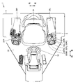
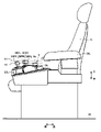
図3は、一実施の形態におけるモータグレーダのキャブ内部の構成を示す平面図である。図3に示されるように、モータグレーダ1は、キャブ3内に、運転席31、右側コンソール32Rと、左側コンソール32Lと、操作レバーと、右側アームレスト33Rと、左側アームレスト33Lと、ステアリングホイール(ハンドル)34とを主に有している。
ステアリングコントロールバルブ82には、ポンプ85から吐出された油が入る。ステアリングホイール34の右回転時には、ステアリングホイール34の回転量に比例した量の油がステアリングコントロールバルブ82のRポートからステアリングシリンダ7a、7bの各々へ吐出される。これによりステアリングホイール34の右回転時には、車両が右旋回するように車輪の操舵が行われる。
本実施の形態によれば、図7に示されるようにステアリング操作レバー5の上面5a1は、上面5a1が回動中心CEの延びる方向から見て円弧形状を有している。これによりオペレータが掌を上面5a1に載せてステアリング操作レバー5を操作する際に、掌を自然な状態で上面5a1に載せてステアリング操作レバー5を操作できる。このためオペレータはステアリング操作レバー5の操作に気を取られることが少なくなり、その分、作業機レバー35RR、35RC、35RL、35FR、35FLの各々の操作に集中することが可能となる。これによりステアリング操作と作業機操作とを同時に行う場合でも、ステアリングと作業機4との双方を繊細に操作することが容易となる。
Claims (8)
- 作業機と、
ステアリング機構と、
運転席と、
前記運転席の側方に配置されたコンソールと、
前記コンソールに支持され、かつ前記作業機を操作する少なくとも1つの作業機レバーと、
前記少なくとも1つの作業機レバーの後方にて前記コンソールに支持され、かつ前記ステアリング機構を操作するステアリング操作レバーとを備え、
前記ステアリング操作レバーは、上面と、前記上面より下方に位置する下部とを有し、
前記上面は、前記下部における回動中心を中心として回動可能であり、かつ前記上面が前記回動中心の延びる方向から見て円弧形状を有し、
前記ステアリング操作レバーは、前記少なくとも1つの作業機レバーのうちの1つとともにオペレータにより片手で同時操作されることができ、これによりステアリング操作と作業機操作とが同時に行われることができる、作業機械。 - 前記上面の前記円弧形状は、前記下部における前記回動中心を中心とした円周に沿う形状である、請求項1に記載の作業機械。
- 前記ステアリング操作レバーは、前記上面を有するレバー本体を有し、
側面視において、前記レバー本体の上端は前記レバー本体の下端に対して前方に向かって上がり傾斜となっている、請求項1に記載の作業機械。 - 前記ステアリング操作レバーは、平面視において矩形形状を有している、請求項1に記載の作業機械。
- 前記ステアリング操作レバーは、前記上面の前記運転席側に位置する側面と、前記上面および前記側面の間に位置する面取りとを有し、
側面視における前記面取りの高さは、後方から前方に向かうにしたがって大きくなる、請求項1に記載の作業機械。 - 前記少なくとも1つの作業機レバーは前後に回動可能であり、前記ステアリング操作レバーは左右に回動可能である、請求項1に記載の作業機械。
- 前記少なくとも1つの作業機レバーは、第1作業機レバーと、第2作業機レバーと、前記第1作業機レバーとの間で前記第2作業機レバーを挟む第3作業機レバーとを有し、
前記第3作業機レバーと前記ステアリング操作レバーとの最大離間距離は、前記第1作業機レバーと前記ステアリング操作レバーとの最大離間距離よりも大きい、請求項1に記載の作業機械。 - 請求項1~7のいずれか1項に記載の前記作業機械よりなる、モータグレーダ。
Priority Applications (4)
| Application Number | Priority Date | Filing Date | Title |
|---|---|---|---|
| JP2018130129A JP7201350B2 (ja) | 2018-07-09 | 2018-07-09 | 作業機械およびモータグレーダ |
| US17/254,995 US20210270012A1 (en) | 2018-07-09 | 2019-02-26 | Work machine and motor grader |
| PCT/JP2019/007336 WO2020012692A1 (ja) | 2018-07-09 | 2019-02-26 | 作業機械およびモータグレーダ |
| CN201980038662.9A CN112236563B (zh) | 2018-07-09 | 2019-02-26 | 作业机械及机动平路机 |
Applications Claiming Priority (1)
| Application Number | Priority Date | Filing Date | Title |
|---|---|---|---|
| JP2018130129A JP7201350B2 (ja) | 2018-07-09 | 2018-07-09 | 作業機械およびモータグレーダ |
Publications (2)
| Publication Number | Publication Date |
|---|---|
| JP2020007795A JP2020007795A (ja) | 2020-01-16 |
| JP7201350B2 true JP7201350B2 (ja) | 2023-01-10 |
Family
ID=69142310
Family Applications (1)
| Application Number | Title | Priority Date | Filing Date |
|---|---|---|---|
| JP2018130129A Active JP7201350B2 (ja) | 2018-07-09 | 2018-07-09 | 作業機械およびモータグレーダ |
Country Status (4)
| Country | Link |
|---|---|
| US (1) | US20210270012A1 (ja) |
| JP (1) | JP7201350B2 (ja) |
| CN (1) | CN112236563B (ja) |
| WO (1) | WO2020012692A1 (ja) |
Families Citing this family (3)
| Publication number | Priority date | Publication date | Assignee | Title |
|---|---|---|---|---|
| JP7727427B2 (ja) * | 2021-07-16 | 2025-08-21 | 株式会社小松製作所 | 作業機械、及び作業機械を制御するための方法 |
| JP7705291B2 (ja) * | 2021-07-16 | 2025-07-09 | 株式会社小松製作所 | 作業機械、及び、作業機械を制御するための方法 |
| JP7798660B2 (ja) * | 2022-04-08 | 2026-01-14 | 株式会社小松製作所 | 作業機械 |
Citations (3)
| Publication number | Priority date | Publication date | Assignee | Title |
|---|---|---|---|---|
| JP2002323931A (ja) | 2001-04-26 | 2002-11-08 | Komatsu Ltd | 油圧ショベル |
| JP2008054536A (ja) | 2006-08-30 | 2008-03-13 | Mitsubishi Agricult Mach Co Ltd | コンバインの操作レバー |
| US20090223092A1 (en) | 2008-03-07 | 2009-09-10 | Deere And Company | Arrangement of steering wheel and operator seat assembly |
Family Cites Families (15)
| Publication number | Priority date | Publication date | Assignee | Title |
|---|---|---|---|---|
| US354367A (en) * | 1886-12-14 | William h | ||
| DE2747589C2 (de) * | 1977-10-24 | 1982-05-27 | International Harvester Company Mbh, 4040 Neuss | Vorrichtung zum Anzeigen von Symbolen an Schalthebeln |
| US4738417A (en) * | 1987-02-02 | 1988-04-19 | Fmc Corporation | Hand operated control |
| JP2000230506A (ja) * | 1999-02-10 | 2000-08-22 | Komatsu Ltd | 操作レバーによるアクチュエータ駆動装置および操作レバー装置 |
| US6550562B2 (en) * | 2000-12-08 | 2003-04-22 | Clark Equipment Company | Hand grip with microprocessor for controlling a power machine |
| USD556790S1 (en) * | 2006-11-17 | 2007-12-04 | Deere & Company | Electronic grader control unit assembly |
| EP2664488B1 (en) * | 2007-09-11 | 2016-07-27 | Hydro-Gear Limited Partnership | Control systems and methods for electric drive utility vehicles |
| US8333250B2 (en) * | 2008-03-07 | 2012-12-18 | Deere & Company | Mounting console with visibility improvements |
| GB2460658A (en) * | 2008-06-04 | 2009-12-09 | Valtra Oy Ab | Driver interface for a utility vehicle |
| CN201738367U (zh) * | 2009-11-25 | 2011-02-09 | 天津建筑机械厂 | 一种推土机专用的左手集中操纵系统 |
| EP2513738A4 (en) * | 2009-12-17 | 2014-01-15 | Volvo Constr Equip Ab | CONTROL LEVER FOR MANUFACTURING A WORKING MACHINE |
| EP2460711B1 (en) * | 2010-03-31 | 2020-04-01 | Hitachi Construction Machinery Co., Ltd. | Steering system for industrial machinery and vehicle-refracting angle changing method |
| US8543298B2 (en) * | 2011-06-03 | 2013-09-24 | Caterpillar Inc. | Operator interface with tactile feedback |
| KR102624793B1 (ko) * | 2016-02-05 | 2024-01-16 | 크라운 이큅먼트 코포레이션 | 자재 취급 차량을 위한 제어 요소 |
| CN107882087A (zh) * | 2016-11-30 | 2018-04-06 | 徐州徐工筑路机械有限公司 | 一种平地机操纵台系统、控制方法及平地机 |
-
2018
- 2018-07-09 JP JP2018130129A patent/JP7201350B2/ja active Active
-
2019
- 2019-02-26 WO PCT/JP2019/007336 patent/WO2020012692A1/ja not_active Ceased
- 2019-02-26 CN CN201980038662.9A patent/CN112236563B/zh active Active
- 2019-02-26 US US17/254,995 patent/US20210270012A1/en not_active Abandoned
Patent Citations (3)
| Publication number | Priority date | Publication date | Assignee | Title |
|---|---|---|---|---|
| JP2002323931A (ja) | 2001-04-26 | 2002-11-08 | Komatsu Ltd | 油圧ショベル |
| JP2008054536A (ja) | 2006-08-30 | 2008-03-13 | Mitsubishi Agricult Mach Co Ltd | コンバインの操作レバー |
| US20090223092A1 (en) | 2008-03-07 | 2009-09-10 | Deere And Company | Arrangement of steering wheel and operator seat assembly |
Also Published As
| Publication number | Publication date |
|---|---|
| CN112236563B (zh) | 2023-04-04 |
| JP2020007795A (ja) | 2020-01-16 |
| CN112236563A (zh) | 2021-01-15 |
| WO2020012692A1 (ja) | 2020-01-16 |
| US20210270012A1 (en) | 2021-09-02 |
Similar Documents
| Publication | Publication Date | Title |
|---|---|---|
| USH1831H (en) | Ergonomic motor grader vehicle control apparatus | |
| CN103046608B (zh) | 施工机器的控制操纵架 | |
| JP7201350B2 (ja) | 作業機械およびモータグレーダ | |
| JP6850078B2 (ja) | モータグレーダ | |
| WO2019102588A1 (ja) | 操作レバー及び作業車両 | |
| WO2018159210A1 (ja) | 建設機械 | |
| JP2017172292A (ja) | 作業車両 | |
| US20070289403A1 (en) | Operating pedal for operating running of industrial vehicle and industrial vehicle having the same | |
| JP7281869B2 (ja) | 作業車両 | |
| JP7338989B2 (ja) | 運転室および作業車両 | |
| CN113412074B (zh) | 驾驶室以及作业车辆 | |
| JP6026143B2 (ja) | 旋回作業機 | |
| JP7481089B2 (ja) | 作業車両 | |
| JP7318144B2 (ja) | 作業機 | |
| JP2020165093A (ja) | 作業機械用カッティングエッジ、作業機械用ブレードおよび作業機械 | |
| US11614766B2 (en) | Machine joystick with comfort and accessibility features | |
| CN115003886B (zh) | 机动平地机以及机动平地机的控制方法 | |
| CN118922604A (zh) | 工程机械、用于控制工程机械的方法及系统 | |
| JP2006077510A (ja) | ホイール式油圧ショベル |
Legal Events
| Date | Code | Title | Description |
|---|---|---|---|
| A621 | Written request for application examination |
Free format text: JAPANESE INTERMEDIATE CODE: A621 Effective date: 20210607 |
|
| A131 | Notification of reasons for refusal |
Free format text: JAPANESE INTERMEDIATE CODE: A131 Effective date: 20220712 |
|
| A521 | Request for written amendment filed |
Free format text: JAPANESE INTERMEDIATE CODE: A523 Effective date: 20220823 |
|
| TRDD | Decision of grant or rejection written | ||
| A01 | Written decision to grant a patent or to grant a registration (utility model) |
Free format text: JAPANESE INTERMEDIATE CODE: A01 Effective date: 20221213 |
|
| A61 | First payment of annual fees (during grant procedure) |
Free format text: JAPANESE INTERMEDIATE CODE: A61 Effective date: 20221222 |
|
| R150 | Certificate of patent or registration of utility model |
Ref document number: 7201350 Country of ref document: JP Free format text: JAPANESE INTERMEDIATE CODE: R150 |
|
| R250 | Receipt of annual fees |
Free format text: JAPANESE INTERMEDIATE CODE: R250 |