JP7201526B2 - Elevator system and elevator maintenance method - Google Patents
Elevator system and elevator maintenance method Download PDFInfo
- Publication number
- JP7201526B2 JP7201526B2 JP2019083434A JP2019083434A JP7201526B2 JP 7201526 B2 JP7201526 B2 JP 7201526B2 JP 2019083434 A JP2019083434 A JP 2019083434A JP 2019083434 A JP2019083434 A JP 2019083434A JP 7201526 B2 JP7201526 B2 JP 7201526B2
- Authority
- JP
- Japan
- Prior art keywords
- maintenance
- car
- control device
- controller
- elevator
- Prior art date
- Legal status (The legal status is an assumption and is not a legal conclusion. Google has not performed a legal analysis and makes no representation as to the accuracy of the status listed.)
- Active
Links
Images



Landscapes
- Maintenance And Inspection Apparatuses For Elevators (AREA)
Description
本発明はエレベーターシステムおよびエレベーター保守方法に関し、例えばエレベーターの保守に係るエレベーターシステムおよびエレベーター保守方法に適用して好適なものである。 TECHNICAL FIELD The present invention relates to an elevator system and an elevator maintenance method, and is suitable for application to, for example, an elevator system and an elevator maintenance method related to elevator maintenance.
エレベーターの保守では、保守員は、エレベーターの乗りかごの上に乗って保守運転を行って昇降路内を点検したり、エレベーターの乗り場側から保守運転を行って乗りかごの動作を点検したりする。 In elevator maintenance, maintenance personnel perform maintenance operations on top of the elevator car to inspect the inside of the hoistway, or perform maintenance operations from the elevator landing side to inspect the operation of the car. .
例えば、エレベーターの保守システムとして、乗りかごの上に設けられて乗りかごの運転制御指令を制御盤に送信する制御装置と、制御装置に接続された保守コントローラと、を備え、保守員が保守コントローラを操作し、乗りかごの運転制御指令を制御装置から制御盤に送信することによって、乗りかごの保守運転を行わせるようにしたものが知られている(特許文献1参照)。 For example, a maintenance system for an elevator includes a control device that is provided on a car and that transmits an operation control command for the car to a control panel, and a maintenance controller that is connected to the control device. is operated to transmit an operation control command for the car from the control device to the control panel, thereby performing maintenance operation of the car (see Patent Document 1).
ここで、機械室がないエレベーターにおいては、保守員は、保守パネルに保守コントローラを取り付け、乗り場側から保守運転を行う必要がある。保守パネルは、乗り場に設けられているので、意匠面の観点から、保守パネルの大きさを小さくしたいという要求がある。 Here, in an elevator without a machine room, maintenance personnel must attach a maintenance controller to the maintenance panel and perform maintenance operations from the landing side. Since the maintenance panel is provided at the platform, there is a demand to reduce the size of the maintenance panel from the viewpoint of design.
この問題を解決するために、現状では、乗り場側の保守コントローラについては、保守パネルには常設せずに、昇降路のピットなどに保管し、乗り場側の保守コントローラを使用するときに持ち出して保守パネルに取り付けるという手法が考えられる。 In order to solve this problem, currently, the maintenance controller on the platform side is not permanently installed on the maintenance panel, but is stored in the pit of the hoistway, etc., and taken out for maintenance when using the maintenance controller on the platform side. A method of attaching to a panel is conceivable.
この場合、エレベーターの乗りかごの上には、保管している保守コントローラと同じ保守コントローラが常設されることになる。つまり、同じ保守コントローラを2つ用意しなければならないという問題がある。 In this case, the same maintenance controller as the stored maintenance controller is permanently installed on the car of the elevator. In other words, there is a problem that two identical maintenance controllers must be prepared.
本発明は以上の点を考慮してなされたもので、用意する保守コントローラの数を低減し得るエレベーターシステム等を提案しようとするものである。 SUMMARY OF THE INVENTION The present invention has been made in consideration of the above points, and intends to propose an elevator system or the like capable of reducing the number of maintenance controllers to be prepared.
かかる課題を解決するため本発明においては、エレベーターの乗りかごの上に設けられる制御装置と、前記エレベーターの乗り場に設けられる保守パネルとの各々に接続可能であり、前記乗りかごの昇降を指示して前記乗りかごを保守運転するための保守コントローラと、前記乗りかごを保守運転する際の前記保守コントローラの設定を模擬するように構成され、前記制御装置に接続可能な保守模擬コネクタと、を備え、前記乗り場側から前記乗りかごの保守運転が行われるときは、前記保守模擬コネクタが前記制御装置に接続され、前記保守コントローラが前記保守パネルに接続されている、ことを特徴とする。 In order to solve such a problem, in the present invention, a control device provided above an elevator car and a maintenance panel provided at the elevator landing can be connected to each of the control device and the maintenance panel to instruct the raising and lowering of the car. and a maintenance simulation connector configured to simulate settings of the maintenance controller during maintenance operation of the car and connectable to the control device. and the maintenance simulation connector is connected to the control device, and the maintenance controller is connected to the maintenance panel when the maintenance operation of the car is performed from the landing side.
上記構成では、例えば、乗りかごの上に常設している保守コントローラを外せるようにしたので、保守コントローラをピットなどに保管する必要がなくなる。また、例えば、乗りかご毎に保守コントローラを2台設置する必要がなくなるため、保守に係る設備の費用を低減することができる。また、例えば、エレベーターを導入する際には、保守コントローラを保守パネルに保管する必要がないので、保守パネルの大きさを小さくすることができる。 In the above configuration, for example, the maintenance controller that is permanently installed on top of the car can be removed, so there is no need to store the maintenance controller in a pit or the like. In addition, for example, since it is not necessary to install two maintenance controllers for each car, it is possible to reduce the cost of equipment related to maintenance. Also, for example, when introducing an elevator, it is not necessary to store the maintenance controller in the maintenance panel, so the size of the maintenance panel can be reduced.
本発明によれば、エレベーターの保守性を高めることができる。 ADVANTAGE OF THE INVENTION According to this invention, the maintainability of an elevator can be improved.
以下図面について、本発明の一実施の形態を詳述する。 One embodiment of the present invention will be described in detail below with reference to the drawings.
(1)第1の実施の形態
図1において、100は全体として第1の実施の形態によるエレベーターシステムを示す。
(1) First Embodiment In FIG. 1, 100 indicates an elevator system according to the first embodiment as a whole.
エレベーターシステム100は、ビルなどに建設された昇降路101を昇降する乗りかご102と、乗りかご102の運転を制御する制御盤103と、乗りかご102の上に設けられ、制御盤103と接続される制御装置104と、乗りかご102の乗り場105(例えば、最上階)に設置されている保守パネル106と、制御装置104に接続可能であり、かつ、保守パネル106に接続可能である保守コントローラ107と、制御装置104に接続可能な保守模擬コネクタ108とを含んで構成される。
The
エレベーターシステム100では、制御装置104は、コネクタ104-1を有し、保守パネル106は、コネクタ106-1を有し、保守コントローラ107は、コネクタ107-1を有する。制御装置104のコネクタ104-1には、保守コントローラ107のコネクタ107-1が接続可能であり(保守コントローラ107が制御装置104に取り付けられたり取り外されたり)、保守模擬コネクタ108が接続可能である(保守模擬コネクタ108が制御装置104に取り付けられたり取り外されたりする)。保守パネル106のコネクタ106-1には、保守コントローラ107のコネクタ107-1が接続可能である(保守コントローラ107が保守パネル106に取り付けられたり取り外されたりする)。
In
ここで、制御盤103は、昇降路101に設置され、乗りかご102の運転を制御する。例えば、制御盤103は、保守員による保守コントローラ107の操作に応じて、乗りかご102を平常運転(平常運転モード)と保守運転(保守運転モード)とを切り換え、乗りかご102の昇降(走行)を制御する。また、例えば、制御盤103は、後述するように、乗りかご102の運転を停止する停止フラグを設定したり、乗りかご102が高速に昇降すること(高速運転)を禁止する禁止フラグを設定したりする。なお、制御盤103は、停止フラグを設定している場合、乗りかご102の昇降を行わない。また、制御盤103は、禁止フラグを設定している場合、乗りかご10の昇降速度を制限し、乗りかご102を高速に昇降させない。
Here, the
付言するならば、制御盤103は、図示は省略するCPU(Central Processing Unit)、RAM(Random Access Memory)、ROM(Read Only Memory)、通信部などを含んで構成される。制御盤103の機能(運転モードの切り換え、フラグの設定など)は、例えば、CPUがROMに格納されたプログラムをRAMに読み出して実行すること(ソフトウェア)により実現されてもよいし、専用の回路などのハードウェアにより実現されてもよいし、ソフトウェアとハードウェアとが組み合わされて実現されてもよい。また、制御盤103の機能の一部は、制御盤103と通信可能な他のコンピュータにより実現されてもよい。
In addition, the
制御装置104は、保守コントローラ107から出力(送信)される信号に基づいて、乗りかご102の運転に係る設定を示す運転モード設定指令(後述の平常運転モード設定指令、保守運転モード設定指令等)を制御盤103に出力する。また、制御装置104は、保守コントローラ107から出力される信号に基づいて、乗りかご102の昇降を指示する昇降制御指令(上昇指令、下降指令など)を制御盤103に出力する。
Based on a signal output (transmitted) from the
保守コントローラ107は、平常運転と保守運転とを切り換える保守員による操作を受け付けたり、乗りかご102の昇降を指示する保守員による操作を受け付けたりするための装置である。なお、保守コントローラ107については、図2を用いて後述する。
The
保守模擬コネクタ108は、乗りかご102を保守運転する際の保守コントローラ107の設定を模擬するように構成され、制御装置104に接続可能なコネクタである。なお、保守模擬コネクタ108については、図3を用いて後述する。
The
また、従来のエレベーターシステム110では、保守コントローラ107と同じ構成のコントローラである保守コントローラ111を備え、保守模擬コネクタ108を備えていない。従来は、例えば、保守コントローラ107が制御装置104に常設され、昇降路101の底部(ピット)に保守コントローラ111が保管されていて、保守員は、乗り場105側から乗りかご102の保守運転を行う場合、保守コントローラ111をピットから持ってきて、保守コントローラ111を保守パネル106に取り付け、保守コントローラ111を操作して乗り場105側からの保守運転を行っている。
Further, in the
この点、エレベーターシステム100では、保守員は、乗り場105側から保守運転を行う場合、乗りかご102上に設置されている保守コントローラ107を制御装置104から取り外して保守模擬コネクタ108を制御装置104に取り付け、取り外した保守コントローラ107を保守パネル106に取り付け、保守コントローラ107を操作して乗り場105側からの保守運転を行う。
In this respect, in the
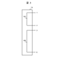
図2は、保守コントローラ107に係る構成の一例を示す図である。保守コントローラ107は、乗りかご102を停止させるための停止ボタン201と、平常運転と保守運転とを切り替えるための切替ツマミ202とを備える。なお、保守コントローラ107は、図2に示す構成に限られるものではない。例えば、保守コントローラ107は、乗りかご102を上昇させるための上昇ボタン、乗りかご102を下降させるための下降ボタン等を備えているが、図示および説明については省略する。
FIG. 2 is a diagram showing an example of the configuration of the
ここで、エレベーターシステム100では、制御装置104は、保守コントローラ107に信号(乗りかご102を停止させるかを検知するための信号である停止検知信号、乗りかご102の運転モードを検知するための信号である運転モード検知信号など)を出力し、保守コントローラ107から入力される信号に基づいて、乗りかご102の運転に係る指令(停止指令、運転モード設定指令など)を制御盤103に出力する。
Here, in the
例えば、図2に示すように、保守コントローラ107は、制御装置104のコネクタ104-1のピン番号「1」のピンに接続される配線211と、制御装置104のコネクタ104-1のピン番号「2」のピンに接続される配線212と、配線211と配線212とを繋いだり切ったりする(電流のオンオフを切り替える)スイッチ213とを備える。
For example, as shown in FIG. 2, the
保守員により停止ボタン201が押下(オン)されると、スイッチ213が開いて電流がオフされ、制御装置104のピン番号「1」のピンから入力された信号(停止検知信号)が制御装置104のピン番号「2」のピンに出力されなくなる。制御装置104では、ピン番号「2」のピンから信号が入力されない場合、乗りかご102を停止する旨の停止指令を制御盤103に通知する。また、保守コントローラ107が制御装置104に接続されていないときも、制御装置104は、ピン番号「2」のピンから信号が入力されないので、乗りかご102を停止する旨の停止指令を制御盤103に通知する。制御盤103は、停止指令を受け取ると、停止フラグを設定し、停止フラグを解除するまで、乗りかご102の昇降を禁止する。
When the
再び、保守員により停止ボタン201が押下(オフ)されると、スイッチ213が閉じて電流がオンされ、制御装置104から入力された信号(停止検知信号)が制御装置104に出力されるようになる。制御装置104では、ピン番号「2」のピンから信号が入力さる場合、乗りかご102を停止しない旨の停止解除指令を制御盤103に通知する。制御盤103は、停止解除指令を受け取ると、停止フラグを解除し、乗りかご102の昇降を許可する。
When the
また、例えば、図2に示すように、保守コントローラ107は、制御装置104のコネクタ104-1のピン番号「3」のピンに接続される配線221と、制御装置104のコネクタ104-1のピン番号「4」のピンに接続される配線222と、制御装置104のコネクタ104-1のピン番号「5」のピンに接続される配線223と、配線221および配線222を接続したり、配線221および配線223を接続したりする(電流の向きを変える)スイッチ224とを備える。
Also, for example, as shown in FIG. The
保守員により切替ツマミ202が保守側に操作されると、スイッチ224により配線221と配線222とが接続される。よって、制御装置104のピン番号「3」のピンから入力された信号(運転モード検知信号)が制御装置104のピン番号「4」のピンに出力される。制御装置104では、ピン番号「4」のピンから信号が入力される場合、乗りかご102を保守運転する旨の保守運転モード設定指令を制御盤103に通知する。制御盤103は、保守運転モード設定指令を受け取ると、乗りかご102の運転モードを保守運転モードに設定する。
When the
保守員により切替ツマミ202が平常側に操作されると、スイッチ224により配線221と配線223とが接続される。よって、制御装置104のピン番号「3」のピンから入力された信号(運転モード検知信号)が制御装置104のピン番号「5」のピンに出力される。制御装置104では、ピン番号「5」のピンから信号が入力される場合、乗りかご102を平常運転する旨の平常運転モード設定指令を制御盤103に通知する。制御盤103は、平常運転モード設定指令を受け取ると、乗りかご102の運転モードを平常運転モードに設定する。
When the
また、制御装置104は、保守コントローラ107が取り外された場合(ピン番号「4」のピンからもピン番号「5」のピンからも信号が入力されない場合)、制御盤103に高速運転を禁止する旨の禁止指令を制御盤103に通知する。制御盤103は、禁止指令を受け取ると、禁止フラグを設定する。制御盤103は、保守員の安全を確保するための所定の操作(例えば、エレベーターの全てのドアを閉じた状態で、制御盤103の電源のオフオンする操作)が行われると、禁止フラグを解除する。かかる所定の操作によれば、乗りかご102が不意に高速に昇降することがないので、保守員が保守コントローラ107を制御装置104に取り付けたときに、乗りかご102が高速に昇降してしまう事態を回避することができる。
Further, when the
図3は、保守模擬コネクタ108に係る構成の一例を示す図である。
FIG. 3 is a diagram showing an example of the configuration of the
図3に示すように、保守模擬コネクタ108は、制御装置104のコネクタ104-1のピン番号「1」のピンとピン番号「2」のピンとに接続される配線301と、制御装置104のコネクタ104-1のピン番号「3」のピンとピン番号「6」のピンとに接続される配線302と、を備える。
As shown in FIG. 3, the
保守模擬コネクタ108が制御装置104に取り付けられると、制御装置104のピン番号「1」のピンから入力された信号(停止検知信号)が制御装置104のピン番号「2」のピンに出力される。制御装置104では、ピン番号「2」のピンから信号が入力される場合、乗りかご102を停止しない旨の停止解除指令を制御盤103に通知する。制御盤103は、停止解除指令を受け取ると、停止フラグを解除し、乗りかご102の昇降を許可する。
When the
また、保守模擬コネクタ108が制御装置104に取り付けられると、制御装置104のピン番号「3」のピンから入力された信号(運転モード検知信号)が制御装置104のピン番号「6」のピンに出力される。制御装置104では、ピン番号「6」のピンから信号が入力される場合、保守パネル106に取り付けられた保守コントローラ107からの乗りかご102の昇降の操作(乗り場105側からの保守運転)を許可する旨の乗り場側保守運転指令を制御盤103に通知する。制御盤103は、乗り場側保守運転指令を受け取ると、乗り場側保守運転フラグを設定し、乗り場105側からの保守運転を許可する。
Further, when the
また、保守模擬コネクタ108が制御装置104から取り外されると、制御装置104では、ピン番号「6」のピンから信号が入力されなくなるので、乗り場105側からの保守運転を許可しない旨の乗り場側保守運転解除指令を制御盤103に通知する。制御盤103は、乗り場側保守運転解除指令を受け取ると、乗り場側保守運転フラグを解除し、乗り場105側からの保守運転を禁止する。
Further, when the
図4は、エレベーターの保守に係る手順(エレベーター保守方法)の一例を示す図である。 FIG. 4 is a diagram showing an example of a procedure (elevator maintenance method) relating to elevator maintenance.
ステップS401では、作業員は、保守コントローラ107の停止ボタン201を押下(オン)して乗りかご102が動かない状態にし、乗りかご102の上に移動する。なお、停止ボタン201がオンされると、停止フラグが設定される。
In step S<b>401 , the operator presses (turns on) the
ステップS402では、作業員は、乗りかご102の上に設置された保守コントローラ107を制御装置104から取り外し、保守模擬コネクタ108を制御装置104に取り付ける(挿入する)。なお、保守コントローラ107が制御装置104から取り外されると、禁止フラグが設定され、保守員の安全を確保するための所定の操作が行われるまで、乗りかご102が高速に昇降しなくなる。また、保守模擬コネクタ108が制御装置104に取り付けられると、停止フラグが解除されるが、乗り場側保守運転フラグが設定され、乗りかご102側からの保守運転が禁止され、乗り場105側からの保守運転が許可される。
In step S<b>402 , the worker removes the
ステップS403では、作業員は、乗り場105の保守パネル106に保守コントローラ107を取り付ける。
In step S<b>403 , the worker attaches the
ステップS404では、作業員は、保守コントローラ107の切替ツマミ202を平常側から保守側に切り替える。なお、切替ツマミ202が平常側から保守側に切り替えられると、保守運転モードが設定される。
In step S404, the operator switches the switching
ステップS405では、作業員は、保守コントローラ107の停止ボタン201を押下(オフ)する。なお、停止ボタン201がオフされると、停止フラグが解除され、乗りかご102の昇降(乗り場105側からの保守運転)が許可される。
In step S<b>405 , the worker presses (turns off) the
ステップS406では、作業員は、保守コントローラ107の上昇ボタン、下降ボタン等を操作して保守運転を行い、保守作業が終了したか否かを判断する。保守員は、保守作業が終了したと判断した場合、ステップS407以降の作業を行う。
In step S406, the worker operates the up button, the down button, etc. of the
ステップS407では、作業員は、保守コントローラ107の停止ボタン201を押下(オン)して乗りかご102が動かない状態にする。なお、停止ボタン201がオンされると、停止フラグが設定される。
In step S407, the worker presses (turns on) the
ステップS408では、作業員は、乗り場105の保守パネル106から保守コントローラ107を取り外し、乗りかご102の上に移動する。
In step S<b>408 , the worker removes the
ステップS409では、作業員は、制御装置104から保守模擬コネクタ108を取り外し、保守コントローラ107を制御装置104に取り付ける。なお、制御装置104から保守模擬コネクタ108が取り外されると、乗り場側保守運転フラグが解除され、乗り場105側からの保守運転が禁止される。
In step S<b>409 , the worker removes the
ステップS410では、作業員は、保守コントローラ107の切替ツマミ202を保守側から平常側に切り替える。なお、切替ツマミ202が保守側から平常側に切り替えられると、平常運転モードが設定される。
In step S410, the operator switches the switching
ステップS411では、作業員は、保守コントローラ107の停止ボタン201を押下(オフ)する。なお、停止ボタン201がオフされると、停止フラグが解除され、乗りかご102の昇降が許可される。
In step S<b>411 , the operator presses (turns off) the
ステップS412では、作業員は、エレベーターの全てのドアを閉じた状態で制御盤103の電源をオフオンする。かかる操作が行わると、制御盤103は、禁止フラグを解除する。
In step S412, the worker turns off and on the
本実施の形態によれば、制御装置から保守コントローラを取り外して保守模擬コネクタを取り付けた際、停止スイッチの短絡と同時に、禁止フラグの設定と乗り場側保守運転フラグとの設定とを行うことにより、安全性を確保しつつ、乗り場側から保守コントローラを使用可能とすることができる。 According to the present embodiment, when the maintenance controller is removed from the control device and the maintenance simulation connector is attached, the stop switch is short-circuited and simultaneously the prohibition flag and the platform side maintenance operation flag are set. The maintenance controller can be used from the platform side while ensuring safety.
(2)他の実施の形態
なお、上述の実施の形態においては、本発明をエレベーターシステムに適用するようにした場合について述べたが、本発明はこれに限らず、この他種々のシステム、装置、方法、プログラムに広く適用することができる。
(2) Other Embodiments In the above-described embodiment, the case where the present invention is applied to an elevator system has been described, but the present invention is not limited to this, and various other systems and devices. , methods and programs.
また、上述の実施の形態においては、所定の操作として、エレベーターの全てのドアを閉じた状態で、制御盤103の電源をオフオンする操作をする場合について述べたが、本発明はこれに限らず、さらに、かかる操作と、保守模擬コネクタ108を所定の装置(制御盤103、保守パネル106など)に取り付ける操作とを所定の操作としてもよい。この場合、例えば、保守模擬コネクタ108を乗りかご102上、昇降路101内などに置き忘れてしまう事態を回避することができる。
Further, in the above-described embodiment, the case of turning off and on the power of the
また、上述の実施の形態においては、乗り場側から保守運転する際の保守模擬コネクタ108について述べたが、本発明はこれに限らない。例えば、平常時の運転を模擬する平常模擬コネクタを備えてもよい。平常運転では、平常模擬コネクタが制御装置104に接続されている。乗りかご102上での保守運転では、平常模擬コネクタが制御装置104から取り外され、保守コントローラ107が制御装置104に取り付けられる。乗り場105側からの保守運転では、平常模擬コネクタが制御装置104から取り外され、保守模擬コネクタ108が制御装置104に取り付けられ、保守コントローラ107が保守パネル106に取り付けられる。このように、保守コントローラ107を常設することなく、保守時に保守員が保守コントローラ107を持参するようにしてもよい。
Further, in the above-described embodiment, the
また、上述の実施の形態においては、制御盤103が昇降路101に設置される場合について述べたが、本発明はこれに限らず、制御盤103が機械室に設置されていてもよい。
Further, in the above embodiment, the case where the
また、上述の実施の形態においては、制御装置104から保守コントローラ107が取り外されたときに禁止フラグを設定する場合について述べたが、本発明はこれに限らず、制御装置104に保守模擬コネクタ108が取り付けられたときに禁止フラグが設定されるようにしてもよい。
Further, in the above-described embodiment, the case where the prohibition flag is set when the
また、上述の実施の形態においては、保守模擬コネクタ108が配線302を有する場合について述べたが、本発明はこれに限らず、保守模擬コネクタ108が、配線302に替えて、制御装置104のコネクタ104-1のピン番号「4」のピンとピン番号「5」のピンとの両方に信号を出力する配線を備えてもよい。
Further, in the above-described embodiment, the case where the
また、上記の説明において、各機能を実現するプログラム、テーブル、ファイル等の情報は、メモリや、ハードディスク、SSD(Solid State Drive)等の記憶装置、または、ICカード、SDカード、DVD等の記録媒体に置くことができる。 In the above description, information such as programs, tables, and files that implement each function is stored in a memory, hard disk, SSD (Solid State Drive), or other storage device, or recorded on an IC card, SD card, DVD, or the like. You can put it on the medium.
本発明は、例えば、以下の特徴的な構成を有する。 The present invention has, for example, the following characteristic configurations.
エレベーターシステム(例えば、エレベーターシステム100)であって、エレベーターの乗りかご(例えば、乗りかご102)の上に設けられる制御装置(例えば、制御装置104)と、上記エレベーターの乗り場(例えば、乗り場105)に設けられる保守パネル(例えば、保守パネル106)との各々に接続可能であり、上記乗りかごの昇降を指示して上記乗りかごを保守運転するための保守コントローラ(例えば、保守コントローラ107)と、上記乗りかごを保守運転する際の上記保守コントローラの設定を模擬するように構成(例えば、制御装置104のピン番号「1」のピンおよびピン番号「2」のピンと接続される配線301と、ピン番号「3」のピンおよびピン番号「6」のピンと接続される配線302を含んで構成)され、上記制御装置に接続可能な保守模擬コネクタ(例えば、保守模擬コネクタ108)と、を備え、上記乗り場側から上記乗りかごの保守運転が行われるときは、上記保守模擬コネクタが上記制御装置に接続され、上記保守コントローラが上記保守パネルに接続されている、ことを特徴とする。
An elevator system (e.g., elevator system 100) comprising a control device (e.g., control device 104) provided on an elevator car (e.g., car 102) and an elevator landing (e.g., landing 105). A maintenance controller (e.g., maintenance controller 107) that can be connected to each of a maintenance panel (e.g., maintenance panel 106) provided in the car and instructs the elevator car to be raised and lowered to perform maintenance operation of the car; A configuration that simulates the settings of the maintenance controller during maintenance operation of the car (for example, a
上記構成では、例えば、乗りかごの上に常設している保守コントローラを外せるようにしたので、保守コントローラをピットなどに保管する必要がなくなる。また、例えば、乗りかご毎に保守コントローラを2台設置する必要がなくなるため、保守に係る設備の費用を低減することができる。また、例えば、エレベーターを導入する際には、保守コントローラを保守パネルに保管する必要がないので、保守パネルの大きさを小さくすることができる。 In the above configuration, for example, the maintenance controller that is permanently installed on top of the car can be removed, so there is no need to store the maintenance controller in a pit or the like. In addition, for example, since it is not necessary to install two maintenance controllers for each car, it is possible to reduce the cost of equipment related to maintenance. Also, for example, when introducing an elevator, it is not necessary to store the maintenance controller in the maintenance panel, so the size of the maintenance panel can be reduced.
上記乗りかごの運転を制御する制御盤(例えば、制御盤103)を備え、上記乗りかごの平常運転が行われるときは、上記保守コントローラが上記制御装置に接続され、上記制御盤は、上記保守コントローラが上記制御装置に接続されていない場合、上記乗りかごの運転を禁止(例えば、乗りかご102の昇降速度を制限)し、上記保守模擬コネクタが上記制御装置に接続された場合、上記保守パネルに接続された上記保守コントローラによる保守運転を許可する(例えば、ステップS402)、ことを特徴とする。
A control panel (for example, a control panel 103) for controlling the operation of the car is provided, and when the car is in normal operation, the maintenance controller is connected to the control device, and the control panel controls the maintenance When the controller is not connected to the control device, the operation of the car is prohibited (for example, the lifting speed of the
ここで、従来のエレベーターにおいて、保守コントローラを取り外した場合、停止スイッチが作動し、乗りかごの運転が禁止されるエレベーターがある。この点、上記構成によれば、例えば、保守模擬コネクタを接続することで、保守運転が行えるようになるので、従来のエレベーターにも適用可能となる。 Here, in some conventional elevators, when the maintenance controller is removed, the stop switch is actuated and the car operation is prohibited. In this respect, according to the above configuration, for example, by connecting a maintenance simulation connector, maintenance operation can be performed, so that it can be applied to a conventional elevator.
上記制御盤は、上記保守コントローラが保守員により上記制御装置から取り外された場合、上記保守員の安全を確保するための所定の操作が行われるまで、上記乗りかごを高速に昇降させることを禁止する(例えば、ステップS402、ステップS412)、ことを特徴とする。 When the maintenance controller is removed from the control device by maintenance personnel, the control panel prohibits the car from being raised or lowered at high speed until a predetermined operation is performed to ensure the safety of the maintenance personnel. (for example, step S402, step S412).
上記構成によれば、例えば、保守員が乗りかごを離れて所定の操作が行われるまでは乗りかごが高速に昇降することがないので、保守員が保守コントローラを制御装置に接続したときに、乗りかごが不意に高速に昇降してしまう事態を回避することができる。 According to the above configuration, for example, the car does not move up and down at high speed until the maintenance person leaves the car and performs a predetermined operation, so when the maintenance person connects the maintenance controller to the control device, It is possible to avoid a situation in which the car is suddenly raised and lowered at high speed.
上記保守模擬コネクタは、上記制御装置から上記乗りかごの運転に係る設定を確認するための信号(例えば、運転モード検知信号)を入力した場合、上記乗り場側から上記乗りかごの保守運転が行われることを示す信号(例えば、ピン番号「6」のピンに入力される信号)を上記制御装置に出力する、ことを特徴とする。 When a signal (for example, an operation mode detection signal) for confirming settings related to the operation of the car is input from the control device to the maintenance simulation connector, maintenance operation of the car is performed from the platform side. It is characterized by outputting a signal (for example, a signal input to a pin of pin number "6") indicating the above to the control device.
また上述した構成については、本発明の要旨を超えない範囲において、適宜に、変更したり、組み替えたり、組み合わせたり、省略したりしてもよい。 Moreover, the above-described configurations may be appropriately changed, rearranged, combined, or omitted within the scope of the present invention.
100……エレベーターシステム、101……昇降路、102……乗りかご、103……制御盤、104……制御装置、105……乗り場、106……保守パネル、107……保守コントローラ、108……保守模擬コネクタ。
100...
Claims (4)
前記乗りかごを保守運転する際の前記保守コントローラの設定を模擬するように構成され、前記制御装置に接続可能な保守模擬コネクタと、
を備え、
前記乗り場側から前記乗りかごの保守運転が行われるときは、前記保守模擬コネクタが前記制御装置に接続され、前記保守コントローラが前記保守パネルに接続され、
前記保守模擬コネクタは、前記制御装置から前記乗りかごの運転に係る設定を確認するための信号を入力した場合、前記乗り場側から前記乗りかごの保守運転が行われることを示す信号を前記制御装置に出力する、
ことを特徴とするエレベーターシステム。 A maintenance unit which is connectable to a control device provided on a car of an elevator and a maintenance panel provided at a landing of the elevator, and which instructs the raising and lowering of the car to maintain and operate the car. a controller;
a maintenance simulation connector configured to simulate settings of the maintenance controller during maintenance operation of the car and connectable to the control device;
with
When maintenance operation of the car is performed from the landing side, the maintenance simulation connector is connected to the control device, the maintenance controller is connected to the maintenance panel,
When a signal for confirming the setting related to the operation of the car is input from the control device, the maintenance simulation connector outputs a signal indicating that the maintenance operation of the car is to be performed from the hall side to the control device. output to
An elevator system characterized by:
前記乗りかごの平常運転が行われるときは、前記保守コントローラが前記制御装置に接続され、
前記制御盤は、前記保守コントローラが前記制御装置に接続されていない場合、前記乗りかごの運転を禁止し、前記保守模擬コネクタが前記制御装置に接続された場合、前記保守パネルに接続された前記保守コントローラによる保守運転を許可する、
ことを特徴とする請求項1に記載のエレベーターシステム。 A control panel for controlling the operation of the car,
When normal operation of the car is performed, the maintenance controller is connected to the control device,
The control panel prohibits the operation of the car when the maintenance controller is not connected to the control device, and the maintenance simulation connector connected to the maintenance panel when the maintenance simulation connector is connected to the control device. allow maintenance operation by the maintenance controller,
The elevator system according to claim 1, characterized in that:
ことを特徴とする請求項2に記載のエレベーターシステム。 When the maintenance controller is removed from the control device by maintenance personnel, the control panel prohibits the car from being raised or lowered at high speed until a predetermined operation is performed to ensure the safety of the maintenance personnel. do,
3. The elevator system according to claim 2, characterized in that:
保守員が、前記乗り場側から前記乗りかごの保守運転を行うとき、
前記保守模擬コネクタを前記制御装置に取り付ける第1のステップと、
前記保守コントローラを前記保守パネルに取り付ける第2のステップと、
を備え、
前記保守模擬コネクタは、前記制御装置から前記乗りかごの運転に係る設定を確認するための信号を入力した場合、前記乗り場側から前記乗りかごの保守運転が行われることを示す信号を前記制御装置に出力する、
ことを特徴とするエレベーター保守方法。 A maintenance unit which is connectable to a control device provided on a car of an elevator and a maintenance panel provided at a landing of the elevator, and which instructs the raising and lowering of the car to maintain and operate the car. An elevator maintenance method for an elevator system, comprising: a controller; and a maintenance simulation connector configured to simulate settings of the maintenance controller during maintenance operation of the car and connectable to the control device,
When maintenance personnel perform maintenance operation of the car from the landing side,
a first step of attaching the maintenance simulation connector to the controller;
a second step of attaching the maintenance controller to the maintenance panel;
with
When a signal for confirming the setting related to the operation of the car is input from the control device, the maintenance simulation connector outputs a signal indicating that the maintenance operation of the car is to be performed from the hall side to the control device. output to
An elevator maintenance method characterized by:
Priority Applications (1)
| Application Number | Priority Date | Filing Date | Title |
|---|---|---|---|
| JP2019083434A JP7201526B2 (en) | 2019-04-24 | 2019-04-24 | Elevator system and elevator maintenance method |
Applications Claiming Priority (1)
| Application Number | Priority Date | Filing Date | Title |
|---|---|---|---|
| JP2019083434A JP7201526B2 (en) | 2019-04-24 | 2019-04-24 | Elevator system and elevator maintenance method |
Publications (2)
| Publication Number | Publication Date |
|---|---|
| JP2020179960A JP2020179960A (en) | 2020-11-05 |
| JP7201526B2 true JP7201526B2 (en) | 2023-01-10 |
Family
ID=73023276
Family Applications (1)
| Application Number | Title | Priority Date | Filing Date |
|---|---|---|---|
| JP2019083434A Active JP7201526B2 (en) | 2019-04-24 | 2019-04-24 | Elevator system and elevator maintenance method |
Country Status (1)
| Country | Link |
|---|---|
| JP (1) | JP7201526B2 (en) |
Families Citing this family (1)
| Publication number | Priority date | Publication date | Assignee | Title |
|---|---|---|---|---|
| WO2021085393A1 (en) | 2019-10-28 | 2021-05-06 | 花王株式会社 | Method for manufacturing fiber deposition body, method for manufacturing film, and method for attaching film |
Citations (2)
| Publication number | Priority date | Publication date | Assignee | Title |
|---|---|---|---|---|
| CN1911770A (en) | 2005-08-08 | 2007-02-14 | 株式会社日立建筑系统 | Elevator reparing operation device |
| JP2018090398A (en) | 2016-12-06 | 2018-06-14 | 東芝エレベータ株式会社 | Inspection system for elevator |
Family Cites Families (2)
| Publication number | Priority date | Publication date | Assignee | Title |
|---|---|---|---|---|
| JPH0192186A (en) * | 1987-09-30 | 1989-04-11 | Hitachi Ltd | Operating device in pit of elevator |
| WO2001027013A1 (en) * | 1999-10-07 | 2001-04-19 | Mitsubishi Denki Kabushiki Kaisha | Elevator maintenance/operation apparatus |
-
2019
- 2019-04-24 JP JP2019083434A patent/JP7201526B2/en active Active
Patent Citations (2)
| Publication number | Priority date | Publication date | Assignee | Title |
|---|---|---|---|---|
| CN1911770A (en) | 2005-08-08 | 2007-02-14 | 株式会社日立建筑系统 | Elevator reparing operation device |
| JP2018090398A (en) | 2016-12-06 | 2018-06-14 | 東芝エレベータ株式会社 | Inspection system for elevator |
Also Published As
| Publication number | Publication date |
|---|---|
| JP2020179960A (en) | 2020-11-05 |
Similar Documents
| Publication | Publication Date | Title |
|---|---|---|
| JP6280879B2 (en) | Maintenance terminal equipment for elevators | |
| KR101755721B1 (en) | Method and apparatus for modernizing an elevator installation | |
| CN107848743A (en) | Apparatus for controlling elevator | |
| AU2015367707B2 (en) | Method for operating an electronic safety system with temporary subscribers | |
| JP7201526B2 (en) | Elevator system and elevator maintenance method | |
| CN113460824A (en) | Elevator safety loop fault detection system, method, equipment and storage medium | |
| CN113692389B (en) | Elevator maintenance system | |
| US12565402B2 (en) | Multi-car elevator system | |
| WO2025123793A1 (en) | Elevator control method and apparatus, elevator controller, elevator safety system and elevator | |
| CN111196537A (en) | Method for controlling movement of elevator car, multi-car elevator system and operating entity | |
| JP4919593B2 (en) | Elevator operation device | |
| RU2696645C2 (en) | Method of operating electronic security system with time members | |
| CN103538987B (en) | Double-deck elevator and control method thereof | |
| JP6578253B2 (en) | Elevator system | |
| JP7307814B2 (en) | Elevator normal operation recovery device and normal operation recovery method | |
| JP2005255275A (en) | Elevator control system | |
| CN108689257A (en) | A kind of building hoist control system | |
| JP7225378B2 (en) | Elevator renewal method | |
| CN206735558U (en) | Multi-inspection loop control device | |
| CN108333962A (en) | power controller | |
| WO2018100599A1 (en) | Elevator maintenance control apparatus and elevator maintenance control method | |
| JP7846870B2 (en) | Elevator testing system and elevator testing method | |
| JP3164910B2 (en) | Escalator operating device | |
| JP6189801B2 (en) | elevator | |
| JP7150158B2 (en) | Elevator renewal method and car equipment controller |
Legal Events
| Date | Code | Title | Description |
|---|---|---|---|
| A621 | Written request for application examination |
Free format text: JAPANESE INTERMEDIATE CODE: A621 Effective date: 20210714 |
|
| A977 | Report on retrieval |
Free format text: JAPANESE INTERMEDIATE CODE: A971007 Effective date: 20220523 |
|
| A131 | Notification of reasons for refusal |
Free format text: JAPANESE INTERMEDIATE CODE: A131 Effective date: 20220705 |
|
| A521 | Request for written amendment filed |
Free format text: JAPANESE INTERMEDIATE CODE: A523 Effective date: 20220824 |
|
| TRDD | Decision of grant or rejection written | ||
| A01 | Written decision to grant a patent or to grant a registration (utility model) |
Free format text: JAPANESE INTERMEDIATE CODE: A01 Effective date: 20221220 |
|
| A61 | First payment of annual fees (during grant procedure) |
Free format text: JAPANESE INTERMEDIATE CODE: A61 Effective date: 20221222 |
|
| R150 | Certificate of patent or registration of utility model |
Ref document number: 7201526 Country of ref document: JP Free format text: JAPANESE INTERMEDIATE CODE: R150 |