JP7204246B2 - canned motor pump - Google Patents
canned motor pump Download PDFInfo
- Publication number
- JP7204246B2 JP7204246B2 JP2021099022A JP2021099022A JP7204246B2 JP 7204246 B2 JP7204246 B2 JP 7204246B2 JP 2021099022 A JP2021099022 A JP 2021099022A JP 2021099022 A JP2021099022 A JP 2021099022A JP 7204246 B2 JP7204246 B2 JP 7204246B2
- Authority
- JP
- Japan
- Prior art keywords
- base unit
- fixed frame
- surface portion
- holding
- motor
- Prior art date
- Legal status (The legal status is an assumption and is not a legal conclusion. Google has not performed a legal analysis and makes no representation as to the accuracy of the status listed.)
- Active
Links
Images


Landscapes
- Connection Of Motors, Electrical Generators, Mechanical Devices, And The Like (AREA)
- Structures Of Non-Positive Displacement Pumps (AREA)
- Motor Or Generator Frames (AREA)
Description
本発明はキャンドモータポンプに関し、特に、構造の安定性が向上されるキャンドモータポンプに関する。 The present invention relates to a canned motor pump, and more particularly to a canned motor pump with improved structural stability.
液体の供給に用いられる従来のキャンドモータポンプとしては、例えば特許文献1に記載されるものが挙げられる。特許文献1に記載されるように、該従来のキャンドモータポンプは、キャンドモータと、該キャンドモータにより回転駆動される羽根車と、該キャンドモータを囲んで保持する保持手段と、該保持手段を保持するプラスチックの強化フレームと、該キャンドモータの前後両側を覆うように、強化フレームに取り付けられるフロントカバー及びリアカバーと、により構成されている。 As a conventional canned motor pump used for liquid supply, there is, for example, the one described in Patent Document 1. As described in Patent Document 1, the conventional canned motor pump includes a canned motor, an impeller rotationally driven by the canned motor, holding means surrounding and holding the canned motor, and the holding means. It is composed of a holding plastic reinforced frame, and a front cover and a rear cover attached to the reinforced frame so as to cover both front and rear sides of the canned motor.
この従来のキャンドモータポンプにおいて、2つの枠部により構成される保持手段は、強化フレーム内に嵌めこまれていると共に、強化フレームに形成される係合リブが保持手段に形成される係合溝の中に嵌まり込むことにより、保持手段と強化フレームとの相対的な構造安定性を保つ構成になっている。 In this conventional canned motor pump, the holding means composed of two frame portions is fitted in the reinforcing frame, and the engaging ribs formed in the reinforcing frame are formed in the holding means. It is configured to fit within the retaining means to maintain relative structural stability between the retaining means and the reinforcing frame.
しかし、該従来のキャンドモータポンプでは、係合リブを保持手段に形成される係合溝の中に嵌め込むことで保持手段を強化フレームに固定する構成を採用するため、保持手段を強化フレームに取り付ける際、係合リブを係合溝に精確に合わせないと取り付けることが出来ず、取り付けに手間が掛かる場合がある。一方、この欠点を解決するために係合溝に遊びを作ると、固定性が落ちることになり、特に、モータの作動中に保持手段と強化フレームとの相対振動が発生すると、騒音が大きくなる上、故障の原因にもなる。 However, in the conventional canned motor pump, the holding means is fixed to the reinforcing frame by fitting the engaging ribs into the engaging grooves formed in the holding means. At the time of attachment, the attachment cannot be performed unless the engagement ribs are precisely aligned with the engagement grooves, and the attachment may be troublesome. On the other hand, if a play is created in the engagement groove to solve this drawback, the fixability will be degraded, and noise will be increased especially if relative vibration between the holding means and the reinforcing frame occurs during operation of the motor. Moreover, it can also cause malfunctions.
上記問題点に鑑みて、本発明は構造の安定性が向上されるキャンドモータポンプの提供を目的とする。 SUMMARY OF THE INVENTION In view of the above problems, it is an object of the present invention to provide a canned motor pump with improved structural stability.
上記目的を達成すべく、本発明は、
所定の軸線の外側において該軸線と平行する前後方向に沿って第1の前端面から第1の後端面まで延伸する中央孔を有するように、プラスチック材料により略環状に形成されたベースユニットと、
前記ベースユニットの前記中央孔内に嵌めこまれて固定されると共に、前記前後方向に沿って前記ベースユニットの前記第1の前端面側に面する第2の前端面から前記ベースユニットの前記第1の後端面側に面する第2の後端面まで延伸するモータ収容孔を囲むように、アルミニウム合金材料により略環状に形成された固定枠と、
前記固定枠の前記モータ収容孔に嵌めこまれて固定されるモータ手段と、
前記ベースユニットの前記第1の前端面を覆うように前記ベースユニットに取り付けられているフロントカバーと、を備え、
前記ベースユニットの前記中央孔に臨む内周面は、前記固定枠を保持する固定枠保持面部を有し、該固定枠保持面部には、複数の第1の係合面と、隣り合う2つの前記第1の係合面の間にそれぞれ介在する第1の曲がり角部と、が形成され、
前記ベースユニットの前記内周面に面する前記固定枠の外周面には、各前記第1の係合面にそれぞれ対応して当接する複数の第2の係合面と、各前記第1の曲がり角部にそれぞれ対応して嵌め込まれる複数の第2の曲がり角部と、が形成され、
前記固定枠は、前記軸線を中心として回転不可能に前記ベースユニットの前記中央孔内に嵌めこまれて固定されることを特徴とするキャンドモータポンプを提供する。
In order to achieve the above object, the present invention
a base unit formed of a plastic material in a substantially annular shape so as to have a central hole extending from a first front end face to a first rear end face along a longitudinal direction outside a predetermined axis and parallel to the axis;
It is fitted and fixed in the central hole of the base unit, and extends from the second front end face facing the first front end face side of the base unit along the front-rear direction to the first front end face of the base unit. a fixing frame made of an aluminum alloy material and formed in a substantially annular shape so as to surround a motor housing hole extending to a second rear end face facing the rear end face of the motor;
a motor means fixed by being fitted into the motor housing hole of the fixed frame;
a front cover attached to the base unit so as to cover the first front end surface of the base unit;
The inner peripheral surface facing the central hole of the base unit has a fixed frame holding surface portion for holding the fixed frame, and the fixed frame holding surface portion has a plurality of first engaging surfaces and two adjacent a first corner portion interposed between the first engagement surfaces, and
The outer peripheral surface of the fixed frame, which faces the inner peripheral surface of the base unit, has a plurality of second engaging surfaces that abut against the respective first engaging surfaces, and each of the first engaging surfaces. a plurality of second bends fitted in corresponding to the bends, respectively;
The canned motor pump is characterized in that the fixed frame is fitted and fixed in the central hole of the base unit so as not to be rotatable about the axis.
上記のように、本発明のキャンドモータポンプは、ベースユニットの前記中央孔の前記固定枠を保持する固定枠保持面部に複数の第1の係合面と、隣り合う2つの前記第1の係合面の間にそれぞれ介在する第1の曲がり角部と、が形成され、そして前記固定枠の外周面には、各前記第1の係合面にそれぞれ対応して当接する複数の第2の係合面と、各前記第1の曲がり角部にそれぞれ対応して嵌め込まれる複数の第2の曲がり角部と、が形成されるので、固定枠はベースユニットの前記中央孔の固定枠保持面部に回転不可能に保持されるようになり、単純な構造で取り付けも簡単な上、構造の安定性が向上されてモータの作動中においても騒音を抑えることができる従来よりも優れたキャンドモータポンプを提供することができる。 As described above, in the canned motor pump of the present invention, the fixed frame holding surface portion holding the fixed frame of the central hole of the base unit has a plurality of first engaging surfaces and two adjacent first engaging surfaces. A plurality of first curved corner portions interposed between the mating surfaces are formed, and a plurality of second engaging portions abutting on the respective first engaging surfaces are formed on the outer peripheral surface of the fixed frame. Since a mating surface and a plurality of second bent corners fitted corresponding to each of the first bent corners are formed, the fixed frame is non-rotatably attached to the fixed frame holding surface portion of the central hole of the base unit. To provide a canned motor pump superior to the conventional one capable of being held as easily as possible, having a simple structure and being easy to install, and capable of suppressing noise even during the operation of the motor by improving the stability of the structure. be able to.
以下、本発明に係るキャンドモータポンプの実施形態について、図面を参照して説明する。 BEST MODE FOR CARRYING OUT THE INVENTION An embodiment of a canned motor pump according to the present invention will be described below with reference to the drawings.
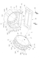
図1は本発明のキャンドモータポンプの一実施形態の構成が示される分解斜視図であり、図2は同実施形態におけるベースユニットと固定枠の構成が示される分解斜視図であり、図3は同実施形態の構成が示される断面図であり、図4は図3におけるIV‐IV線に沿った断面の構成が示される断面図であり、図5は同実施形態の構成が示される要部拡大断面図である。 FIG. 1 is an exploded perspective view showing the configuration of one embodiment of the canned motor pump of the present invention, FIG. 2 is an exploded perspective view showing the configuration of a base unit and a fixed frame in the same embodiment, and FIG. FIG. 4 is a cross-sectional view showing the configuration of the same embodiment, FIG. 4 is a cross-sectional view showing the configuration of a cross section taken along line IV-IV in FIG. 3, and FIG. 5 is a main part showing the configuration of the same embodiment. It is an expanded sectional view.
図1に示されるように、キャンドモータポンプは、大まかにベースユニット10と、固定枠20と、モータ手段30と、フロントカバー40と、リアカバー50と、支持台60と、複数の第1の固定ねじ70と、複数の第2の固定ねじ80と、を備えている。
As shown in FIG. 1, the canned motor pump roughly includes a
図1~図3に示されるように、ベースユニット10は、所定の軸線Lの外側において該軸線と平行する前後方向Xに沿って第1の前端面11から第1の後端面12まで延伸する中央孔13を囲むように、プラスチック材料により略環状に形成されている。
As shown in FIGS. 1 to 3, the
ベースユニット10の構成に使用できるプラスチック材料としては、耐薬品性の強い材料を用いることが好ましく、例えば、ポリプロピレン、ガラス繊維強化ポリプロピレン(GRFPP)、ポリフッ化ビニリデン(PVDF)、カーボン繊維強化ETFE(CFR-ETFE)などが挙げられる。
As a plastic material that can be used to construct the
固定枠20は、ベースユニット10の中央孔13内に嵌めこまれて固定されると共に、前後方向Xに沿ってベースユニット10の第1の前端面11側に面する第2の前端面21からベースユニット10の第1の後端面12側に面する第2の後端面22まで延伸するモータ収容孔23を囲むように、アルミニウム合金材料により略環状に形成されている。
The
モータ手段30は、固定枠20のモータ収容孔23に嵌めこまれて固定される。
The motor means 30 is fixed by being fitted into the
フロントカバー40は、ベースユニット10の第1の前端面11を覆うようにベースユニット10に取り付けられている。
The
支持台60はベースユニット10の下端にある底板140に取り付けられ、第1の固定ねじ70及び第2の固定ねじ80は、固定枠20をベースユニット10に固定する。
The
本発明において、ベースユニット10の中央孔13に臨む内周面14は、固定枠20を保持する固定枠保持面部145を有し、該固定枠保持面部145には、複数の第1の係合面1401と、隣り合う2つの第1の係合面1401の間にそれぞれ介在する第1の曲がり角部1402と、が形成されている。
In the present invention, the inner
ベースユニット10の内周面14に面する固定枠20の外周面24には、内周面14の形状に対応して、各第1の係合面1401にそれぞれ対応して当接する複数の第2の係合面243と、各第1の曲がり角部1402にそれぞれ対応して嵌め込まれる複数の第2の曲がり角部244と、が形成されている。この構成により、固定枠20は、軸線Lを中心として回転不可能にベースユニット10の中央孔13内に嵌めこまれて固定される。
The outer
また、各第2の係合面243には、それぞれ複数のスロットエリア25と、該複数のスロットエリア25を仕切る仕切り壁26とが形成されている。この構成により、固定枠20全体の重量を減らすと共に、固定枠20の空気との接触面の面積を増やして放熱効果を向上させる効果が得られる。固定枠20の放熱効果を向上させることにより、モータ手段30が故障する確率を減らし、その使用寿命を延長することができる。
A plurality of
以下、この実施形態におけるベースユニット10と固定枠20とモータ手段30との詳細の構成関係について、詳しく説明する。
Hereinafter, detailed structural relationships among the
この実施形態において、モータ手段30は、図3に示されるように、軸線Lに沿って延伸する回転軸35と、回転軸35の外周に固定されて回転軸35と共に回転するロータ32と、ロータ32を囲んで保持するロータ保持部31と、ロータ保持部31の外側に固定されると共に、固定枠20のモータ収容孔23に嵌めこまれて固定されるステータ33と、ベースユニット10の第1の前端面11が面する側において、ロータ32と連動して回転するように配置されて第1の前端面11と共にフロントカバー40に覆われる羽根車34と、を有している。
In this embodiment, the motor means 30 includes, as shown in FIG. a
モータ手段30としては従来のものを用いることができるのでその細かい構成に関する詳しい説明は省略する。 Since a conventional motor means 30 can be used, a detailed description of its detailed configuration is omitted.
ベースユニット10の第1の前端面11に取り付けられているフロントカバー40には、流体入り口41と、流体出口42との2つの開口が形成されている。つまり、該フロントカバー40はベースユニット10の第1の前端面11及びモータ手段30の羽根車34と共に流体入り口41及び流体出口42に連通する流体通路43を画成し、羽根車34の回転により流体入り口41から流体通路43内に流入する流体を流体出口42へ送り出す機能を発揮する。
A
ベースユニット10の中央孔13に臨む内周面14は、第1の前端面11から前後方向Xの後方へ延伸してモータ手段30のロータ保持部31の第1の前端面11側(前側)にある端部を囲んで保持する第1のモータ保持面部141と、第1のモータ保持面部141の後端縁に略直交してモータ手段30のステータ33に当接する第1の当接面部142と、第1の当接面部142の外周縁から前後方向Xに沿って第1の後端面12側(後側)へ延伸してモータ手段30のステータ33の第1の前端面11側(前側)にある端部を囲んで保持する第2のモータ保持面部143と、第2のモータ保持面部143の後端縁に略直交して固定枠20に当接する第2の当接面部144と、第2の当接面部144の外周縁から前後方向Xに沿って第1の後端面12側(後側)へ延伸して固定枠20を囲んで保持する固定枠保持面部145と、固定枠保持面部145の後端縁に略直交する第3の当接面部146と、第3の当接面部146の外周縁から前後方向Xに沿って第1の後端面12側(後側)へ延伸する環状延伸部147と、を有するように形成されている。
The inner
固定枠20は、上記構成を有するベースユニット10の中央孔13内に、第2の当接面部144と固定枠保持面部145とにより画成される空間内に嵌めこまれて固定される。
The
更に、図2に示されるように、ベースユニット10は、台座部101と、該台座部101と共に中央孔13を画成する保持枠部102と、を有するように構成されている。該台座部101には、中央孔13に向かって開口する2つの係合溝148が形成されている。
Further, as shown in FIG. 2, the
内周面14の各第1の係合面1401と、各第1の曲がり角部1402とは、保持枠部102に形成されている。
Each first
固定枠20の外周面24には、ベースユニット10の2つの係合溝148内にそれぞれ嵌めこまれている2つの係合突起241が更に形成されている。
The outer
本実施形態において、リアカバー50はアルミニウム合金材料により作製されたものであり、上述のように、固定枠20の第2の後端面22を覆うと共に、固定枠20及びベースユニット10の第3の当接面部146に当接するように、ベースユニット10及び固定枠20に取り付けられている。また、この実施形態において、図3及び図5に示されるように、リアカバー50はベースユニット10の内周面14の環状延伸部147の内側に収容され、固定枠20に当接する内側面51と、該内側面51の反対側にある端部52と、該端部52から突起する複数の放熱フィン53と、を有している。
In this embodiment, the
図5に示されているように、第1の固定ねじ70は、前後方向Xに沿って、ベースユニット10の第1の後端面12の後方から、リアカバー50と固定枠20とを挿通してベースユニット10の前記第2の当接面部144にねじ込まれる。
As shown in FIG. 5, the first fixing
従って、各第1の固定ねじ70に対応して、リアカバー50には第1の通過孔54、固定枠20には第1の貫通孔27、そしてベースユニット10には第1のねじ孔15が形成されている。
Therefore, corresponding to each first fixing
即ち、この実施形態では、前後方向Xに沿って延伸する複数の第1の固定ねじ70を用いて横方向で固定枠20をベースユニット10に固定する構成になっている。
That is, in this embodiment, the fixing
また、この実施形態において、第1の固定ねじ70及び第1の固定ねじ70に対応する第1の通過孔54と第1の貫通孔27と第1のねじ孔15の数は4であるが、本発明としてはこれに限らず、必要に応じて第1の固定ねじ70の数を変更することができる。
In this embodiment, the number of the first fixing
支持台60は、ベースユニット10の台座部101を下から支持するように該台座部101に取り付けられる。この構成により、ベースユニット10を支持して運搬の途中などでは特に損傷を受けやすい支持台60のみを取り替えることができる。
The
そして第2の固定ねじ80は、支持台60の下方から、支持台60とベースユニット10の台座部101とを挿通して固定枠20にねじ込まれる。
The
従って、各第2の固定ねじ80に対応して、支持台60には第2の通過孔63、ベースユニット10には第2の貫通孔16、そして固定枠20には第2のねじ孔28が形成されている。
Therefore, corresponding to each second fixing
即ち、この実施形態では、支持台60の下方から複数の第2の固定ねじ80を用いて縦方向で固定枠20をベースユニット10に固定する構成になっている。
That is, in this embodiment, the fixed
また、この実施形態において、第2の固定ねじ90及び第2の固定ねじ80に対応する第2の通過孔63と第2の貫通孔16と第2のねじ孔28の数は4であるが、本発明としてはこれに限らず、必要に応じて第2の固定ねじ80の数を変更することができる。
In this embodiment, the number of the second through
更に、図2に示されているように、ベースユニット10の中央孔13に臨む内周面14の第1の当接面部142と第2の当接面部144の表面には、それぞれ複数の凹陥部103と、隣り合う2つの凹陥部103の間に介在する補強リブ104と、が形成されている。この構成により、ベースユニット10を製作する材料コストを節約すると共に、成形収縮率の影響を抑え、全体の重量を減らし、その構造的強度を強化することもできる。
Further, as shown in FIG. 2, the surfaces of the first
上記のように、本発明のキャンドモータポンプは、ベースユニット10の中央孔13の固定枠20を保持する固定枠保持面部145に複数の第1の係合面1401と、隣り合う2つの第1の係合面1401の間にそれぞれ介在する第1の曲がり角部1402と、が形成され、そして固定枠20の外周面24には、各第1の係合面1401にそれぞれ対応して当接する複数の第2の係合面243と、各第1の曲がり角部1402にそれぞれ対応して嵌め込まれる複数の第2の曲がり角部244と、が形成されるので、各第1の係合面1401と各第2の係合面243の当接及び各第1の曲がり角部1402と各第2の曲がり角部244との嵌合により、固定枠20はベースユニット10の中央孔13の固定枠保持面部145に回転不可能に保持されるようになる。
As described above, the canned motor pump of the present invention has a plurality of first
また、ベースユニット10の2つの係合溝148内に固定枠20の2つの係合突起241がそれぞれ嵌めこまれる構成により、固定枠20のベースユニット10への取り付け作業は簡単となり、ベースユニット10の固定枠20に対する保持安定性にも寄与する。
In addition, since the two
更に、横方向の第1の固定ねじ70と縦方向の第2の固定ねじ80を用いて固定枠20をベースユニット10に固定するので、固定枠20は更に安定にベースユニット10に保持固定されるようになる。
Furthermore, since the fixing
以上、本発明の実施形態を説明したが、本発明はこれらに限定されるものではなく、最も広い解釈の精神および範囲内に含まれる様々な構成として、全ての修飾および均等な構成を包含するものとする。 Although the embodiments of the present invention have been described above, the present invention is not limited to these, and includes all modifications and equivalent configurations as various configurations included within the spirit and scope of the broadest interpretation. shall be
上記のように、本発明は、単純な構造で取り付けも簡単な上、構造の安定性が向上されてモータの作動中においても騒音を抑えることができる従来よりも優れたキャンドモータポンプを提供することができる。 INDUSTRIAL APPLICABILITY As described above, the present invention provides a superior canned motor pump that is simple in structure, easy to install, has improved structural stability, and can suppress noise during operation of the motor. be able to.
10 ベースユニット
101 台座部
102 保持枠部
103 凹陥部
104 補強リブ
11 第1の前端面
12 第1の後端面
13 中央孔
14 内周面
140 底板
1401 第1の係合面
1402 第1の曲がり角部
141 第1のモータ保持面部
142 第1の当接面部
143 第2のモータ保持面部
144 第2の当接面部
145 固定枠保持面部
146 第3の当接面部
147 環状延伸部
148 係合溝
15 第1のねじ孔
16 第2の貫通孔
20 固定枠
21 第2の前端面
22 第2の後端面
23 モータ収容孔
24 外周面
241 係合突起
243 第2の係合面
244 第2の曲がり角部
25 スロットエリア
26 仕切り壁
27 第1の貫通孔
28 第2のねじ孔
30 モータ手段
31 ロータ保持部
32 ロータ
33 ステータ
34 羽根車
35 回転軸
40 フロントカバー
41 流体入り口
42 流体出口
43 流体通路
50 リアカバー
51 内側面
52 端部
53 放熱フィン
54 第1の通過孔
60 支持台
63 第2の通過孔
70 第1の固定ねじ
80 第2の固定ねじ
L 軸線
X 前後方向
10
Claims (7)
前記ベースユニットの前記中央孔内に嵌めこまれて固定されると共に、前記前後方向に沿って前記ベースユニットの前記第1の前端面側に面する第2の前端面から前記ベースユニットの前記第1の後端面側に面する第2の後端面まで延伸するモータ収容孔を囲むように、アルミニウム合金材料により略環状に形成された固定枠と、
前記固定枠の前記モータ収容孔に嵌めこまれて固定されるモータ手段と、
前記ベースユニットの前記第1の前端面を覆うように前記ベースユニットに取り付けられているフロントカバーと、を備え、
前記ベースユニットの前記中央孔に臨む内周面は、前記固定枠を保持する固定枠保持面部を有し、該固定枠保持面部には、複数の第1の係合面と、隣り合う2つの前記第1の係合面の間にそれぞれ介在する第1の曲がり角部と、が形成され、
前記ベースユニットの前記内周面に面する前記固定枠の外周面には、各前記第1の係合面にそれぞれ対応して当接する複数の第2の係合面と、各前記第1の曲がり角部にそれぞれ対応して嵌め込まれる複数の第2の曲がり角部と、が形成され、
前記固定枠は、前記軸線を中心として回転不可能に前記ベースユニットの前記中央孔内に嵌めこまれて固定されており、
前記モータ手段は、前記軸線に沿って延伸する回転軸と、
前記回転軸と共に回転するロータと、
前記ロータを囲んで保持するロータ保持部と、
前記ロータ保持部の外側に固定されると共に、前記固定枠の前記モータ収容孔に嵌めこまれて固定されるステータと、
前記ベースユニットの前記第1の前端面が面する側において、前記ロータと連動して回転するように配置されて前記第1の前端面と共に前記フロントカバーに覆われる羽根車と、
を有しており、
前記ベースユニットの前記中央孔に臨む前記内周面は、
前記第1の前端面から前記前後方向の後方へ延伸して前記モータ手段の前記ロータ保持部の前記第1の前端面側にある端部を囲んで保持する第1のモータ保持面部と、
前記第1のモータ保持面部の後端縁に略直交して前記モータ手段の前記ステータに当接する第1の当接面部と、
前記第1の当接面部の外周縁から前記前後方向に沿って前記第1の後端面側へ延伸して前記モータ手段の前記ステータの前記第1の前端面側にある端部を囲んで保持する第2のモータ保持面部と、
前記第2のモータ保持面部の後端縁に略直交して前記固定枠に当接する第2の当接面部と、
前記第2の当接面部の外周縁から前記前後方向に沿って前記第1の後端面側へ延伸して前記固定枠を囲んで保持する前記固定枠保持面部と、
前記固定枠保持面部の後端縁に略直交する第3の当接面部と、
前記第3の当接面部の外周縁から前記前後方向に沿って前記第1の後端面側へ延伸する環状延伸部と、を有するように形成されており、
前記固定枠は、前記第2の当接面部と前記固定枠保持面部とにより画成される空間内に嵌めこまれて固定されることを特徴とするキャンドモータポンプ。 a base unit formed of a plastic material in a substantially annular shape so as to have a central hole extending from a first front end face to a first rear end face along a longitudinal direction outside a predetermined axis and parallel to the axis;
It is fitted and fixed in the central hole of the base unit, and extends from the second front end face facing the first front end face side of the base unit along the front-rear direction to the first front end face of the base unit. a fixing frame made of an aluminum alloy material and formed in a substantially annular shape so as to surround a motor housing hole extending to a second rear end face facing the rear end face of the motor;
a motor means fixed by being fitted into the motor housing hole of the fixed frame;
a front cover attached to the base unit so as to cover the first front end face of the base unit;
The inner peripheral surface facing the central hole of the base unit has a fixed frame holding surface portion for holding the fixed frame, and the fixed frame holding surface portion has a plurality of first engaging surfaces and two adjacent a first corner portion interposed between the first engagement surfaces, and
The outer peripheral surface of the fixed frame, which faces the inner peripheral surface of the base unit, has a plurality of second engaging surfaces that abut against the respective first engaging surfaces, and each of the first engaging surfaces. a plurality of second bends fitted in corresponding to the bends, respectively;
The fixed frame is fitted and fixed in the central hole of the base unit so as not to be rotatable about the axis ,
the motor means includes a rotating shaft extending along the axis;
a rotor that rotates together with the rotating shaft;
a rotor holding portion that surrounds and holds the rotor;
a stator fixed to the outside of the rotor holding portion and fixed by being fitted into the motor housing hole of the fixed frame;
an impeller arranged to rotate in conjunction with the rotor on the side of the base unit facing the first front end face and covered with the front cover together with the first front end face;
and
The inner peripheral surface facing the central hole of the base unit,
a first motor holding surface portion extending rearward in the longitudinal direction from the first front end surface to surround and hold an end portion of the rotor holding portion of the motor means located on the first front end surface side;
a first contact surface portion that contacts the stator of the motor means substantially orthogonally to the rear edge of the first motor holding surface portion;
Extending from the outer peripheral edge of the first contact surface portion to the first rear end surface side along the front-rear direction, the end portion of the stator of the motor means on the first front end surface side is surrounded and held. a second motor holding surface portion for
a second contact surface portion that is substantially perpendicular to the rear edge of the second motor holding surface portion and that contacts the fixed frame;
the fixed frame holding surface portion extending from the outer peripheral edge of the second contact surface portion to the first rear end surface side along the front-rear direction to surround and hold the fixed frame;
a third contact surface portion substantially perpendicular to the rear edge of the fixed frame holding surface portion;
an annular extending portion extending from the outer peripheral edge of the third contact surface portion to the first rear end surface side along the front-rear direction,
The canned motor pump according to claim 1, wherein the fixed frame is fitted and fixed in a space defined by the second abutment surface portion and the fixed frame holding surface portion .
各前記第1の曲がり角部と、各前記第1の係合面は、前記保持枠部に形成されており、
前記固定枠の前記外周面には、前記ベースユニットの前記2つの係合溝内にそれぞれ嵌めこまれている2つの係合突起が更に形成されている
ことを特徴とする請求項1に記載のキャンドモータポンプ。 The base unit is configured to have a pedestal and a holding frame defining the central hole together with the pedestal, and the pedestal has two openings facing the central hole. two engaging grooves are formed, and each of the first corners and each of the first engaging surfaces are formed on the holding frame,
2. The apparatus according to claim 1, wherein the outer peripheral surface of the fixed frame is further formed with two engaging projections that are respectively fitted into the two engaging grooves of the base unit. Canned motor pump.
該支持台を前記ベースユニットに固定する第2の固定ねじと、を更に備えることを特徴とする請求項2に記載のキャンドモータポンプ。 a support base attached to the pedestal portion of the base unit so as to support the pedestal portion from below;
3. The canned motor pump of claim 2, further comprising a second fixing screw for fixing said support base to said base unit.
Priority Applications (1)
| Application Number | Priority Date | Filing Date | Title |
|---|---|---|---|
| JP2021099022A JP7204246B2 (en) | 2021-06-14 | 2021-06-14 | canned motor pump |
Applications Claiming Priority (1)
| Application Number | Priority Date | Filing Date | Title |
|---|---|---|---|
| JP2021099022A JP7204246B2 (en) | 2021-06-14 | 2021-06-14 | canned motor pump |
Publications (2)
| Publication Number | Publication Date |
|---|---|
| JP2022190614A JP2022190614A (en) | 2022-12-26 |
| JP7204246B2 true JP7204246B2 (en) | 2023-01-16 |
Family
ID=84601868
Family Applications (1)
| Application Number | Title | Priority Date | Filing Date |
|---|---|---|---|
| JP2021099022A Active JP7204246B2 (en) | 2021-06-14 | 2021-06-14 | canned motor pump |
Country Status (1)
| Country | Link |
|---|---|
| JP (1) | JP7204246B2 (en) |
Families Citing this family (1)
| Publication number | Priority date | Publication date | Assignee | Title |
|---|---|---|---|---|
| EP4496862A1 (en) | 2022-03-22 | 2025-01-29 | Ricoh Company, Ltd. | Adhesive structure and manufacturing method thereof, electronic component and manufacturing method thereof, and adhesive layer for transfer |
Citations (3)
| Publication number | Priority date | Publication date | Assignee | Title |
|---|---|---|---|---|
| JP2013247790A (en) | 2012-05-28 | 2013-12-09 | Panasonic Corp | Brushless motor |
| JP2016220285A (en) | 2015-05-14 | 2016-12-22 | アスモ株式会社 | Brushless motor |
| TWM577069U (en) | 2018-12-20 | 2019-04-21 | 日益電機股份有限公司 | Canned magnetic pump device |
-
2021
- 2021-06-14 JP JP2021099022A patent/JP7204246B2/en active Active
Patent Citations (3)
| Publication number | Priority date | Publication date | Assignee | Title |
|---|---|---|---|---|
| JP2013247790A (en) | 2012-05-28 | 2013-12-09 | Panasonic Corp | Brushless motor |
| JP2016220285A (en) | 2015-05-14 | 2016-12-22 | アスモ株式会社 | Brushless motor |
| TWM577069U (en) | 2018-12-20 | 2019-04-21 | 日益電機股份有限公司 | Canned magnetic pump device |
Also Published As
| Publication number | Publication date |
|---|---|
| JP2022190614A (en) | 2022-12-26 |
Similar Documents
| Publication | Publication Date | Title |
|---|---|---|
| JP3225328U (en) | Canned motor pump device | |
| US8047803B2 (en) | Fan apparatus | |
| JP7204246B2 (en) | canned motor pump | |
| JPH10100511A5 (en) | ||
| JP6840408B2 (en) | Can do motor device | |
| US20100178181A1 (en) | Heat-dissipation structure for motor | |
| JP2006336642A (en) | Centrifugal fan and its frame | |
| EP3730849B1 (en) | Fresh air module, air conditioner indoor unit, and air conditioner | |
| KR200237388Y1 (en) | Computer case | |
| JP3225327U (en) | Canned motor pump device | |
| JP7211638B2 (en) | canned motor pump | |
| KR20220003002U (en) | Canned motor pump | |
| KR102565740B1 (en) | Canned motor pump | |
| WO2018099411A1 (en) | Vacuum pump installation box | |
| US20090004966A1 (en) | Ventilating Exhaust fan and Outlet Fitting Assembly | |
| JP5924151B2 (en) | Hot water storage water heater | |
| TWM263554U (en) | Fixing device for heat dissipation fan of server | |
| JP2024025730A (en) | server | |
| CN110793140B (en) | Water pump storage device for cooling fan and cooling fan | |
| CN214499485U (en) | Fan structure and fan | |
| JP2004245568A (en) | Outdoor unit for air conditioner | |
| JP5804790B2 (en) | Assembly structure of the electric retractable unit in the electric retractable mirror | |
| CN115163504B (en) | Canned magnetic pump for improved heat dissipation | |
| WO2022021983A1 (en) | Air duct assembly, fan assembly, and electric heater | |
| CN211560466U (en) | Handle and electric toothbrush |
Legal Events
| Date | Code | Title | Description |
|---|---|---|---|
| A621 | Written request for application examination |
Free format text: JAPANESE INTERMEDIATE CODE: A621 Effective date: 20210614 |
|
| A131 | Notification of reasons for refusal |
Free format text: JAPANESE INTERMEDIATE CODE: A131 Effective date: 20220506 |
|
| A521 | Request for written amendment filed |
Free format text: JAPANESE INTERMEDIATE CODE: A523 Effective date: 20220802 |
|
| TRDD | Decision of grant or rejection written | ||
| A01 | Written decision to grant a patent or to grant a registration (utility model) |
Free format text: JAPANESE INTERMEDIATE CODE: A01 Effective date: 20221129 |
|
| A61 | First payment of annual fees (during grant procedure) |
Free format text: JAPANESE INTERMEDIATE CODE: A61 Effective date: 20221221 |
|
| R150 | Certificate of patent or registration of utility model |
Ref document number: 7204246 Country of ref document: JP Free format text: JAPANESE INTERMEDIATE CODE: R150 |
|
| R250 | Receipt of annual fees |
Free format text: JAPANESE INTERMEDIATE CODE: R250 |