JP7204287B2 - Terminal, wireless communication method, base station and system - Google Patents
Terminal, wireless communication method, base station and system Download PDFInfo
- Publication number
- JP7204287B2 JP7204287B2 JP2020508861A JP2020508861A JP7204287B2 JP 7204287 B2 JP7204287 B2 JP 7204287B2 JP 2020508861 A JP2020508861 A JP 2020508861A JP 2020508861 A JP2020508861 A JP 2020508861A JP 7204287 B2 JP7204287 B2 JP 7204287B2
- Authority
- JP
- Japan
- Prior art keywords
- cell
- carrier
- measurement
- frequency
- information
- Prior art date
- Legal status (The legal status is an assumption and is not a legal conclusion. Google has not performed a legal analysis and makes no representation as to the accuracy of the status listed.)
- Active
Links
Images


Classifications
-
- H—ELECTRICITY
- H04—ELECTRIC COMMUNICATION TECHNIQUE
- H04W—WIRELESS COMMUNICATION NETWORKS
- H04W36/00—Hand-off or reselection arrangements
- H04W36/0005—Control or signalling for completing the hand-off
- H04W36/0083—Determination of parameters used for hand-off, e.g. generation or modification of neighbour cell lists
- H04W36/0085—Hand-off measurements
- H04W36/0094—Definition of hand-off measurement parameters
-
- H—ELECTRICITY
- H04—ELECTRIC COMMUNICATION TECHNIQUE
- H04W—WIRELESS COMMUNICATION NETWORKS
- H04W24/00—Supervisory, monitoring or testing arrangements
- H04W24/10—Scheduling measurement reports ; Arrangements for measurement reports
-
- H—ELECTRICITY
- H04—ELECTRIC COMMUNICATION TECHNIQUE
- H04W—WIRELESS COMMUNICATION NETWORKS
- H04W36/00—Hand-off or reselection arrangements
-
- H—ELECTRICITY
- H04—ELECTRIC COMMUNICATION TECHNIQUE
- H04W—WIRELESS COMMUNICATION NETWORKS
- H04W56/00—Synchronisation arrangements
-
- H—ELECTRICITY
- H04—ELECTRIC COMMUNICATION TECHNIQUE
- H04W—WIRELESS COMMUNICATION NETWORKS
- H04W56/00—Synchronisation arrangements
- H04W56/001—Synchronization between nodes
-
- H—ELECTRICITY
- H04—ELECTRIC COMMUNICATION TECHNIQUE
- H04W—WIRELESS COMMUNICATION NETWORKS
- H04W56/00—Synchronisation arrangements
- H04W56/001—Synchronization between nodes
- H04W56/0015—Synchronization between nodes one node acting as a reference for the others
-
- Y—GENERAL TAGGING OF NEW TECHNOLOGICAL DEVELOPMENTS; GENERAL TAGGING OF CROSS-SECTIONAL TECHNOLOGIES SPANNING OVER SEVERAL SECTIONS OF THE IPC; TECHNICAL SUBJECTS COVERED BY FORMER USPC CROSS-REFERENCE ART COLLECTIONS [XRACs] AND DIGESTS
- Y02—TECHNOLOGIES OR APPLICATIONS FOR MITIGATION OR ADAPTATION AGAINST CLIMATE CHANGE
- Y02D—CLIMATE CHANGE MITIGATION TECHNOLOGIES IN INFORMATION AND COMMUNICATION TECHNOLOGIES [ICT], I.E. INFORMATION AND COMMUNICATION TECHNOLOGIES AIMING AT THE REDUCTION OF THEIR OWN ENERGY USE
- Y02D30/00—Reducing energy consumption in communication networks
- Y02D30/70—Reducing energy consumption in communication networks in wireless communication networks
Landscapes
- Engineering & Computer Science (AREA)
- Computer Networks & Wireless Communication (AREA)
- Signal Processing (AREA)
- Mobile Radio Communication Systems (AREA)
Description
本開示は、次世代移動通信システムにおける端末、無線通信方法、基地局及びシステムに関する。 The present disclosure relates to terminals, wireless communication methods, base stations and systems in next-generation mobile communication systems.
UMTS(Universal Mobile Telecommunications System)ネットワークにおいて、更なる高速データレート、低遅延などを目的としてロングタームエボリューション(LTE:Long Term Evolution)が仕様化された(非特許文献1)。また、LTE(LTE Rel.8、9)の更なる大容量、高度化などを目的として、LTE-A(LTEアドバンスト、LTE Rel.10、11、12、13)が仕様化された。 In the UMTS (Universal Mobile Telecommunications System) network, long term evolution (LTE: Long Term Evolution) has been specified for the purpose of further high data rate, low delay, etc. (Non-Patent Document 1). In addition, LTE-A (LTE Advanced, LTE Rel. 10, 11, 12, 13) was specified for the purpose of further increasing the capacity and sophistication of LTE (LTE Rel. 8, 9).
LTEの後継システム(例えば、FRA(Future Radio Access)、5G(5th generation mobile communication system)、5G+(plus)、NR(New Radio)、NX(New radio access)、FX(Future generation radio access)、LTE Rel.14又は15以降などともいう)も検討されている。 LTE successor systems (for example, FRA (Future Radio Access), 5G (5th generation mobile communication system), 5G + (plus), NR (New Radio), NX (New radio access), FX (Future generation radio access), LTE Also referred to as Rel.14 or 15 or later) is also under consideration.
既存のLTEシステム(例えば、LTE Rel.8-13)において、ユーザ端末(UE:User Equipment)は、同期信号(SS:Synchronization Signal)を検出し、ネットワーク(例えば、基地局(eNB:eNode B))との同期をとるとともに、接続するセルを識別する(例えば、セルID(Identifier)によって識別する)。このような処理はセルサーチとも呼ばれる。同期信号は、例えば、PSS(Primary Synchronization Signal)及び/又はSSS(Secondary Synchronization Signal)を含む。 In the existing LTE system (e.g., LTE Rel.8-13), the user terminal (UE: User Equipment) detects a synchronization signal (SS: Synchronization Signal), the network (e.g., base station (eNB: eNode B) ) and identifies the cell to be connected (for example, identified by a cell ID (Identifier)). Such processing is also called a cell search. Synchronization signals include, for example, PSS (Primary Synchronization Signal) and/or SSS (Secondary Synchronization Signal).
また、UEは、ブロードキャスト情報(例えば、マスタ情報ブロック(MIB:Master Information Block)、システム情報ブロック(SIB:System Information Block)など)を受信して、ネットワークとの通信のための設定情報(システム情報などと呼ばれてもよい)を取得する。 In addition, the UE receives broadcast information (eg, master information block (MIB: Master Information Block), system information block (SIB: System Information Block), etc.), setting information for communication with the network (system information etc.).
MIBは、ブロードキャストチャネル(PBCH:Physical Broadcast Channel)で送信されてもよい。SIBは、下りリンク(DL)共有チャネル(PDSCH:Physical Downlink Shared Channel)で送信されてもよい。 The MIB may be transmitted on a broadcast channel (PBCH: Physical Broadcast Channel). The SIB may be transmitted on a downlink (DL) shared channel (PDSCH).
将来の無線通信システム(以下、単にNRとも表記する)では、同期信号ブロック(SSB:Synchronization Signal Block)を用いた測定が利用される。SSBを用いた測定に関するタイミング設定(SMTC:SSB-based Measurement Timing Configuration)が、UEに通知される。UEは、設定されたSMTCウィンドウ内において、測定対象のSSBに基づく測定を実施する。 A future wireless communication system (hereinafter simply referred to as NR) will utilize measurements using a synchronization signal block (SSB). Timing configuration for measurement using SSB (SMTC: SSB-based Measurement Timing Configuration) is notified to the UE. The UE performs measurements based on the SSBs to be measured within the configured SMTC window.
また、NRにおいては、接続中のサービングセルとは異なるセルの測定を行う異周波測定(inter-frequency measurement)がサポートされる。測定の際、UEはセルのフレームタイミングを認識する必要がある。UEは、フレームタイミングをSSBインデックスなどに基づいて判断できる。SSBインデックスを把握するためには、SSBに含まれるPBCHの復号処理及び/又はPBCH用復調用参照信号(DMRS:DeModulation Reference Signal)の系列パターンの検出処理が必要である。 Also, in NR, inter-frequency measurement that measures a cell different from the serving cell being connected is supported. When making measurements, the UE needs to be aware of the cell's frame timing. The UE can determine the frame timing based on the SSB index or the like. Decoding of PBCH included in SSB and/or detection of sequence pattern of demodulation reference signal (DMRS) for PBCH are necessary to grasp the SSB index.
しかしながら、異周波測定においてUEが必ず測定対象セルについてPBCHの上記処理を行わなければならないとすると、測定遅延が増大し、通信スループットなどが低下するという課題がある。 However, if the UE must always perform the above processing of PBCH for the measurement target cell in the inter-frequency measurement, there is a problem that the measurement delay increases and the communication throughput decreases.
そこで、本開示は、異周波測定を行う場合であっても、通信スループットの低減を抑制できる端末、無線通信方法、基地局及びシステムを提供することを目的の1つとする。 Accordingly, one object of the present disclosure is to provide a terminal, a wireless communication method, a base station, and a system capable of suppressing a decrease in communication throughput even when different frequency measurement is performed.
本開示の一態様に係る端末は、サービングセルの第1のキャリアと異なる第2のキャリアにおける異周波測定を指示する測定指示を受信する受信部と、隣接セルによって送信される同期信号ブロック(Synchronization Signal Block(SSB))のインデックスをサービングセル又は前記異周波測定の対象周波数のセルのタイミングに基づいて導出できることを示す情報が前記測定指示に含まれる場合に、前記第2のキャリアにおける複数のセルのフレーム境界が合っていると想定する制御部と、を有し、前記制御部は、前記情報が前記測定指示に含まれる場合に、前記第2のキャリアにおける1つのセルのタイミングを用いて、前記第2のキャリアにおける各セルのSSBのインデックスを導出する。 A terminal according to an aspect of the present disclosure includes a receiving unit that receives a measurement instruction that instructs inter-frequency measurement on a second carrier that is different from the first carrier of the serving cell, and a synchronization signal block transmitted by a neighboring cell (Synchronization Signal Block (SSB)) index can be derived based on the timing of the serving cell or the cell of the target frequency of the inter-frequency measurement, when the measurement instruction includes the frame of a plurality of cells in the second carrier a control unit that assumes a boundary , wherein the control unit uses the timing of one cell on the second carrier to calculate the second carrier if the information is included in the measurement indication. Derive the SSB index for each cell on the 2 carriers .
本開示の一態様によれば、異周波測定を行う場合であっても、通信スループットの低減を抑制できる。 According to one aspect of the present disclosure, it is possible to suppress a decrease in communication throughput even when different frequency measurement is performed.
既存のLTEシステムにおいて、UEは、接続中のサービングキャリアとは異なる非サービングキャリアにおいて測定を行う異周波測定(inter-frequency measurement)をサポートする。 In existing LTE systems, a UE supports inter-frequency measurement in which measurements are made on a non-serving carrier that is different from the serving carrier to which it is connected.
UEは、メジャメントギャップ(MG:Measurement Gap)において、使用周波数(RF:Radio Frequency)をサービングキャリアから非サービングキャリアに切り替え(リチューニングし)、参照信号などを用いて測定した後、使用周波数を非サービングキャリアからサービングキャリアに切り替える。 UE, in the measurement gap (MG: Measurement Gap), the use frequency (RF: Radio Frequency) is switched from the serving carrier to the non-serving carrier (retuning), after measuring using a reference signal, etc., the use frequency is non- Switch from serving carrier to serving carrier.
ここで、MGとは、異周波測定を行うための期間であり、UEは、当該期間において、通信中のキャリアでの送受信を停止して別の周波数のキャリアでの測定を行う。 Here, MG is a period for performing inter-frequency measurement, and the UE stops transmission/reception on a carrier in communication during this period and performs measurement on a carrier of another frequency.
LTEにおいて、MGを使って異周波キャリアを測定している間は、RFを切り替えているためサービングセルでの送受信ができない。一方で、それ以外のケース(例えば、同周波測定)ではメジャメントに関連して送受信の制約は生じない。 In LTE, while different frequency carriers are being measured using MG, RF is switched, so transmission and reception in the serving cell cannot be performed. On the other hand, in other cases (for example, same-frequency measurement), there are no transmission/reception restrictions related to measurements.
NRにおいては、以下のメジャメントが検討されている:
(1)MG不要の周波数内メジャメント(Intra-frequency measurement without MG)、
(2)MG要の周波数内メジャメント(Intra-frequency measurement with MG)、
(3)周波数間メジャメント(Inter-frequency measurement)。In NR, the following measurements are considered:
(1) MG unnecessary intra-frequency measurement (Intra-frequency measurement without MG),
(2) MG required intra-frequency measurement (Intra-frequency measurement with MG),
(3) Inter-frequency measurement.
上記(1)のMG不要の周波数内メジャメントは、RFリチューニングを必要としない同周波測定とも呼ばれる。上記(2)のMG要の周波数内メジャメントは、RFリチューニングを必要とする同周波測定とも呼ばれる。例えば、アクティブBWP(BandWidth Part)の帯域内に測定対象信号が含まれない場合、同周波測定でもRFリチューニングが必要なので、上記(2)の測定となる。 The MG-free intra-frequency measurement of (1) above is also called same-frequency measurement that does not require RF retuning. The MG-required intra-frequency measurement of (2) above is also called the same-frequency measurement that requires RF retuning. For example, if the signal to be measured is not included in the band of the active BWP (BandWidth Part), RF retuning is required even for same-frequency measurement, so the above measurement (2) is performed.
ここで、BWPは、NRにおいて設定されるコンポーネントキャリア(CC:Component Carrier)内の、1つ以上の部分的な周波数帯域に該当する。BWPは、部分周波数帯域、部分帯域などと呼ばれてもよい。 Here, BWP corresponds to one or more partial frequency bands within a component carrier (CC: Component Carrier) set in NR. A BWP may also be referred to as a partial frequency band, partial band, or the like.
上記(3)の周波数間メジャメントは、異周波測定とも呼ばれる。当該異周波測定は、MGを使うことを想定する。しかしながら、UEがギャップなし測定(gap less measurement)のUE能力(UE capability)を基地局(例えば、BS(Base Station)、送受信ポイント(TRP:Transmission/Reception Point)、eNB(eNodeB)、gNB(NR NodeB)などと呼ばれてもよい)に報告する場合には、MGなしの異周波測定が可能である。 The inter-frequency measurement of (3) above is also called inter-frequency measurement. It is assumed that the different frequency measurement uses MG. However, the UE is a base station (for example, BS (Base Station), transmission / reception point (TRP: Transmission / Reception Point), eNB (eNodeB), gNB (NR Node B), etc.), inter-frequency measurements without MG are possible.
NRにおいて、MGを使って同周波キャリア又は異周波キャリアを測定している間は、RFを切り替えているためサービングセルでの送受信ができない。 In NR, while same-frequency carriers or different-frequency carriers are being measured using MG, RF is switched, so transmission and reception in the serving cell cannot be performed.
LTE、NRなどにおいて、同周波測定及び/又は異周波測定に関して、非サービングキャリアの参照信号受信電力(RSRP:Reference Signal Received Power)、受信信号強度(RSSI:Received Signal Strength Indicator)及び参照信号受信品質(RSRQ:Reference Signal Received Quality)、SINR(Signal to Interference plus Noise Ratio)、の少なくとも1つが測定されてもよい。 Reference Signal Received Power (RSRP), Received Signal Strength Indicator (RSSI) and Reference Signal Received Quality of non-serving carriers for same-frequency measurements and/or inter-frequency measurements in LTE, NR, etc. At least one of (RSRQ: Reference Signal Received Quality) and SINR (Signal to Interference plus Noise Ratio) may be measured.
ここで、RSRPは、所望信号の受信電力であり、例えば、セル固有参照信号(CRS:Cell-specific Reference Signal)、チャネル状態情報参照信号(CSI-RS:Channel State Information-Reference Signal)などの少なくとも1つを用いて測定される。RSSIは、所望信号の受信電力と、干渉及び雑音電力とを含む合計の受信電力である。RSRQは、RSSIに対するRSRPの比である。 Here, RSRP is the received power of the desired signal, for example, at least cell-specific reference signal (CRS: Cell-specific Reference Signal), channel state information reference signal (CSI-RS: Channel State Information-Reference Signal), etc. Measured using one. RSSI is the total received power including the received power of the desired signal and the interference and noise power. RSRQ is the ratio of RSRP to RSSI.
当該所望信号は、同期信号ブロック(SSB:Synchronization Signal Block)に含まれる信号であってもよい。SSBは、同期信号(SS:Synchronization Signal)及びブロードキャストチャネル(ブロードキャスト信号、PBCH、NR-PBCHなどともいう)を含む信号ブロックであり、SS/PBCHブロックなどと呼ばれてもよい。 The desired signal may be a signal included in a synchronization signal block (SSB). An SSB is a signal block that includes a synchronization signal (SS) and a broadcast channel (also called a broadcast signal, PBCH, NR-PBCH, etc.), and may be called an SS/PBCH block or the like.
SSBに含まれるSSは、PSS(Primary Synchronization Signal)、SSS(Secondary Synchronization Signal)などを含んでもよい。SSBは、1以上のシンボル(例えば、OFDMシンボル)によって構成される。SSB内では、PSS、SSS及びPBCHがそれぞれ異なる1以上のシンボルに配置されてもよい。例えば、SSBは、1シンボルのPSS、1シンボルのSSS、及び2又は3シンボルのPBCHを含む、計4又は5シンボルによって構成されてもよい。 The SS included in the SSB may include a PSS (Primary Synchronization Signal), an SSS (Secondary Synchronization Signal), and the like. The SSB is composed of one or more symbols (eg, OFDM symbols). Within the SSB, the PSS, SSS and PBCH may each be placed in one or more different symbols. For example, the SSB may consist of a total of 4 or 5 symbols, including 1 symbol of PSS, 1 symbol of SSS, and 2 or 3 symbols of PBCH.
なお、SS(又はSSB)を用いて行われる測定はSS(又はSSB)測定と呼ばれてもよい。SS(又はSSB)測定としては、例えばSS-RSRP、SS-RSRQ、SS-SINR測定などが行われてもよい。SS(又はSSB)測定には、PSS、SSS及びPBCHに対応する復調用参照信号(DMRS:DeModulation Reference Signal)などが用いられてもよい。 Note that measurements performed using SS (or SSB) may be referred to as SS (or SSB) measurements. As SS (or SSB) measurements, for example, SS-RSRP, SS-RSRQ, SS-SINR measurements, etc. may be performed. For SS (or SSB) measurement, demodulation reference signals (DMRS: DeModulation Reference Signals) corresponding to PSS, SSS, and PBCH may be used.
UEは、第1の周波数帯(FR1:Frequency Range 1)及び第2の周波数帯(FR2:Frequency Range 2)の少なくとも1つの周波数帯(キャリア周波数)を用いて通信(信号の送受信、測定など)を行ってもよい。 UE communicates using at least one frequency band (carrier frequency) of the first frequency band (FR1: Frequency Range 1) and the second frequency band (FR2: Frequency Range 2) (signal transmission/reception, measurement, etc.) may be performed.
例えば、FR1は、6GHz以下の周波数帯(サブ6GHz(sub-6GHz))であってもよいし、FR2は、24GHzよりも高い周波数帯(above-24GHz)であってもよい。FR1は、サブキャリア間隔(SCS:Sub-Carrier Spacing)として15、30及び60kHzのうちから少なくとも1つが用いられる周波数レンジと定義されてもよいし、FR2は、SCSとして60及び120kHzのうちから少なくとも1つが用いられる周波数レンジと定義されてもよい。なお、FR1及びFR2の周波数帯、定義などはこれらに限られず、例えばFR1がFR2よりも高い周波数帯であってもよい。 For example, FR1 may be a frequency band below 6 GHz (sub-6 GHz), and FR2 may be a frequency band above 24 GHz (above-24 GHz). FR1 may be defined as a frequency range in which at least one of 15, 30 and 60 kHz is used as the Sub-Carrier Spacing (SCS), and FR2 is at least one of 60 and 120 kHz as the SCS. One may be defined as the frequency range used. Note that the frequency bands and definitions of FR1 and FR2 are not limited to these, and for example, FR1 may be a higher frequency band than FR2.
FR2は、時分割複信(TDD:Time Division Duplex)バンドのみに用いられてもよい。FR2は、複数の基地局間において同期運用されることが好ましい。FR2に複数のキャリアが含まれる場合、これらのキャリアは同期運用されることが好ましい。 FR2 may be used only for Time Division Duplex (TDD) bands. FR2 is preferably operated synchronously among a plurality of base stations. If FR2 contains multiple carriers, these carriers are preferably operated synchronously.
UEは、同周波測定及び/又は異周波測定に関する情報(例えば、「MeasObjectNR」情報要素)を、例えば上位レイヤシグナリング、物理レイヤシグナリング又はこれらの組み合わせを用いて基地局から通知(設定)されてもよい。 The UE may be notified (configured) from the base station using, for example, higher layer signaling, physical layer signaling, or a combination thereof, for example, information on intra-frequency measurement and/or inter-frequency measurement (for example, "MeasObjectNR" information element). good.
ここで、上位レイヤシグナリングは、例えば、RRC(Radio Resource Control)シグナリング、MAC(Medium Access Control)シグナリング、ブロードキャスト情報などのいずれか、又はこれらの組み合わせであってもよい。 Here, the higher layer signaling may be, for example, RRC (Radio Resource Control) signaling, MAC (Medium Access Control) signaling, broadcast information, or a combination thereof.
MACシグナリングは、例えば、MAC制御要素(MAC CE(Control Element))、MAC PDU(Protocol Data Unit)などを用いてもよい。ブロードキャスト情報は、例えば、マスタ情報ブロック(MIB:Master Information Block)、システム情報ブロック(SIB:System Information Block)、最低限のシステム情報(RMSI:Remaining Minimum System Information)などであってもよい。 MAC signaling may use MAC Control Element (MAC CE (Control Element)), MAC PDU (Protocol Data Unit), etc., for example. The broadcast information may be, for example, a Master Information Block (MIB), a System Information Block (SIB), Remaining Minimum System Information (RMSI), or the like.
同周波測定及び/又は異周波測定に関する情報は、SSB及び/又はCSI-RSを用いた同周波測定、異周波測定などに適用できる情報を含んでもよい。同周波測定及び/又は異周波測定に関する情報は、例えば、測定対象の周波数帯(キャリア)、測定対象のキャリアの同期の有無、測定対象の信号(DMRS、CSI-RSなど)のリソース位置(スロット番号、シンボル番号、RBインデックスなど)、SSBメジャメントのタイミング設定(SMTC:SSB-based Measurement Timing Configuration)、測定対象のSSBのインデックスなどを含んでもよい。SSBインデックスは、SSBのリソース位置に関連付けられてもよい。 The information about same-frequency measurement and/or different-frequency measurement may include information applicable to same-frequency measurement, different-frequency measurement, etc. using SSB and/or CSI-RS. Information on the same frequency measurement and / or different frequency measurement, for example, the frequency band (carrier) to be measured, the presence or absence of synchronization of the carrier to be measured, the signal to be measured (DMRS, CSI-RS, etc.) resource position (slot number, symbol number, RB index, etc.), SSB measurement timing configuration (SMTC: SSB-based Measurement Timing Configuration), index of the SSB to be measured, and the like. The SSB index may be associated with the resource location of the SSB.
なお、測定対象のキャリアの同期の有無は、例えば、測定対象キャリアがサービングセルと同期しているか(隣接セル(neighbour cell)(又は周辺セル)によって送信されるSSBのインデックスをサービングセルのタイミングに基づいて導出できるか)に関する情報(パラメータ「useServingCellTimingForSync」と呼ばれてもよい)を用いてRRCシグナリングによってUEに設定されてもよい。当該情報は、SSBインデックス導出に関する情報、キャリア(又はセル)同期に関する情報などと呼ばれてもよい。 The presence or absence of synchronization of the carrier to be measured is determined, for example, by whether the carrier to be measured is synchronized with the serving cell (the index of the SSB transmitted by the neighbor cell (or neighboring cell) is based on the timing of the serving cell. can be derived) (which may be called the parameter “useServingCellTimingForSync”) may be configured in the UE by RRC signaling. The information may be called information on SSB index derivation, information on carrier (or cell) synchronization, and the like.
同周波測定及び/又は異周波測定に関する情報(例えば、「MeasObjectNR」情報要素)にuseServingCellTimingForSyncが含まれる場合、useServingCellTimingForSyncが有効(enabled)と想定されてもよい。useServingCellTimingForSyncが含まれない場合useServingCellTimingForSyncが無効(disabled)と想定されてもよい。 If useServingCellTimingForSync is included in the information regarding intra-frequency measurement and/or inter-frequency measurement (eg, 'MeasObjectNR' information element), useServingCellTimingForSync may be assumed to be enabled. If useServingCellTimingForSync is not included, it may be assumed that useServingCellTimingForSync is disabled.
SMTC期間内における測定対象のSSBの位置は、ビットマップ(パラメータ「ssb-ToMeasure」と呼ばれてもよい)によって通知されてもよい。当該ビットマップは、測定対象の周波数帯に関連付けられてもよい。例えば、測定対象の周波数帯が高い周波数帯であるほどより長いビットマップを用いて当該SSBインデックスが通知されてもよい。 The position of the SSB to be measured within the SMTC period may be signaled by a bitmap (which may be called a parameter “ssb-ToMeasure”). The bitmap may be associated with the frequency band to be measured. For example, the higher the frequency band to be measured, the longer the bitmap may be used to notify the SSB index.
SMTCは、SSB測定期間(SMTCウィンドウ、測定タイミングなどと呼ばれてもよい)の長さ、周期、タイミングオフセットなどを含んでもよい。UEは、設定されたSMTCウィンドウ内において、測定対象のSSBに基づく測定を実施する。 The SMTC may include the length, period, timing offset, etc. of the SSB measurement period (which may be referred to as the SMTC window, measurement timing, etc.). The UE performs measurements based on the SSBs to be measured within the configured SMTC window.
異周波測定用MGを設定するためのUE能力(UE capability)シグナリングがサポートされてもよい。当該UE能力シグナリングとしては、例えばFR1及びFR2のそれぞれの異周波測定用MGを別々に設定できる。 UE capability signaling for configuring MG for inter-frequency measurement may be supported. As the UE capability signaling, for example, MGs for inter-frequency measurement of FR1 and FR2 can be set separately.
例えば、UEは、FR1個別、FR2個別及びUE個別の少なくとも1つに該当するギャップのためのMG長(length又はduration)、MG繰り返し周期などを含む能力シグナリングを通知してもよい。 For example, the UE may signal capability signaling including the MG length (or duration), MG repetition period, etc. for gaps corresponding to at least one of FR1 individual, FR2 individual and UE individual.
<SSBと同期の関係>
ところで、NRでは、LTEと同様に、同一周波数上におけるセル間同期運用及びセル間非同期運用だけでなく、周波数キャリア間の同期運用及び非同期運用(異なる周波数キャリアの同期運用及び非同期運用)が可能である。ここで、「同期」は、複数のキャリア(又は複数のセル)について、無線フレーム境界(又はフレームタイミング)が合っているかどうか、とシステムフレーム番号(SFN:System Frame Number)まで合っているか、の2つの観点がある。<Relationship between SSB and synchronization>
By the way, in NR, as in LTE, not only inter-cell synchronous operation and inter-cell asynchronous operation on the same frequency but also synchronous operation and asynchronous operation between frequency carriers (synchronous operation and asynchronous operation of different frequency carriers) are possible. be. Here, "synchronization" refers to whether or not the radio frame boundary (or frame timing) is matched for multiple carriers (or multiple cells), and whether or not the system frame number (SFN) is matched. There are two points of view.
UEは、SSBに含まれるPBCHを復号する(読む)ことによって、SFNを把握してもよい。例えば、NRのPBCHは、10ビットのSFNを示す情報を含んでもよい。 The UE may learn the SFN by decoding (reading) the PBCH contained in the SSB. For example, the NR PBCH may contain information indicating a 10-bit SFN.
UEは、対象セル(又はキャリア)のフレームタイミングを、SSBインデックス及びハーフフレームインデックス(HFI:Half Frame Index)に基づいて判断してもよい。また、UEは、対象セル(又はキャリア)のフレームタイミングを、SSBインデックスに基づいて判断してもよい。 The UE may determine the frame timing of the target cell (or carrier) based on the SSB index and Half Frame Index (HFI). The UE may also determine the frame timing for the target cell (or carrier) based on the SSB index.
UEは、SSBインデックスを、FR1においては、PBCH用DMRSの系列パターンから検出してもよい。UEは、SSBインデックスを、FR2においては、PBCH用DMRSの系列パターンから下位3ビットの情報を決定し、残りの上位3ビットの情報をPBCHのペイロードから取得してもよい。 The UE may detect the SSB index from the PBCH DMRS sequence pattern in FR1. For the SSB index, the UE may determine the lower 3-bit information from the PBCH DMRS sequence pattern in FR2, and acquire the remaining upper 3-bit information from the PBCH payload.
UEは、HFIを、3GHz以下のキャリア(バンドと呼ばれてもよい)においては、PBCH用DMRSの系列パターンから検出してもよい。UEは、HFIを、3GHz以上のキャリアにおいては、PBCHのペイロードから取得してもよい。 The UE may detect HFI from the sequence pattern of DMRS for PBCH in carriers (which may be called bands) of 3 GHz or lower. The UE may obtain the HFI from the payload of the PBCH on carriers above 3 GHz.
セル間同期時及び/又はキャリア間同期時においては、UEは、観測(測定)対象セルの特定の信号がどのタイミングで受信されるかを、接続中のサービングセルのフレームタイミング(又は同じ周波数キャリアの他セルのフレームタイミング)から導出してもよい。この場合、UEの信号検出動作などを簡略化できる。 At the time of inter-cell synchronization and / or inter-carrier synchronization, the UE determines at which timing the specific signal of the observation (measurement) target cell is received, the frame timing of the serving cell being connected (or of the same frequency carrier frame timing of other cells). In this case, the signal detection operation of the UE and the like can be simplified.
例えば、同周波測定に関する情報(例えば、同周波測定に関する情報を含むMeasObjectNR)において、useServingCellTimingForSyncが有効な場合、UEは当該周波数のサービングセルのフレームタイミングに基づいて、検出した周辺(隣接)セルのSSBのインデックスを導出できるため、周辺セルのPBCHの中身(SSBインデックスの情報など)を読んだり、PBCH用DMRSの系列パターンを検出しなくてもよい。 For example, in information on same-frequency measurements (eg, MeasObjectNR including information on same-frequency measurements), if useServingCellTimingForSync is enabled, the UE detects based on the frame timing of the serving cell of the frequency, the SSB of the neighboring (adjacent) cells detected. Since the index can be derived, it is not necessary to read the contents of the PBCH of neighboring cells (such as SSB index information) or detect the sequence pattern of DMRS for PBCH.
一方、異周波測定の場合、当該異周波における「サービングセル」は、測定時には存在しない。このため、同じ周波数のサービングセルのフレームタイミングに基づいて、隣接セルのSSBのインデックスを導出することはできない。 On the other hand, in the case of inter-frequency measurement, the "serving cell" in the inter-frequency does not exist at the time of measurement. Therefore, it is not possible to derive the index of the neighbor cell's SSB based on the frame timing of the serving cell on the same frequency.
しかしながら、異周波測定においてSSBインデックスの報告が必要な場合に、UEが最低1つのセルについて必ずPBCHを復号しなければならない、又は必ずPBCH用DMRSの系列パターンを検出しなければならないとすると、測定遅延が増大し、通信スループットなどが低下するという課題がある。ハンドオーバーの場合にも、同様の問題がある。 However, if it is necessary to report the SSB index in inter-frequency measurement, the UE must always decode the PBCH for at least one cell, or must always detect the sequence pattern of the DMRS for PBCH. There is a problem that delay increases and communication throughput decreases. A similar problem exists in the case of handover.
本発明者らは、異周波測定を行う場合であっても、通信スループットの低減を抑制するためのUE動作を着想した。 The present inventors conceived a UE operation for suppressing a decrease in communication throughput even when inter-frequency measurement is performed.
以下、本開示に係る実施形態について、図面を参照して詳細に説明する。各実施形態に係る無線通信方法は、それぞれ単独で適用されてもよいし、組み合わせて適用されてもよい。 Hereinafter, embodiments according to the present disclosure will be described in detail with reference to the drawings. The wireless communication method according to each embodiment may be applied independently, or may be applied in combination.
(無線通信方法)
一実施形態においては、useServingCellTimingForSyncは、異周波測定において、SSBインデックスの導出を簡略化できるか否か(接続中サービングセルのフレームタイミングを用いてSSBインデックスを導出できるか否か)に関する情報として用いられてもよい。(Wireless communication method)
In one embodiment, useServingCellTimingForSync is used as information on whether or not the derivation of the SSB index can be simplified in inter-frequency measurements (whether or not the SSB index can be derived using the frame timing of the currently connected serving cell). good too.
例えば、UEは、異周波測定指示(異周波測定に関する「MeasObjectNR」情報要素)においてuseServingCellTimingForSyncが有効な(含まれる)場合、測定対象周波数のキャリアと少なくとも一つのサービングセル間が同期していると想定してもよい。UEは、異周波測定指示においてuseServingCellTimingForSyncが有効な場合、接続中サービングセルのフレームタイミングを使って測定対象周波数のセルのSSBインデックスを導出してもよい。 For example, if useServingCellTimingForSync is valid (included) in the inter-frequency measurement instruction (the "MeasObjectNR" information element for inter-frequency measurement), the UE assumes that the carrier of the measurement target frequency and at least one serving cell are synchronized. may When useServingCellTimingForSync is valid in the inter-frequency measurement instruction, the UE may derive the SSB index of the cell of the measurement target frequency using the frame timing of the currently connected serving cell.
つまり、UEは、異周波測定時であっても、当該異周波におけるキャリアと接続中サービングセル間が同期している場合には、接続中サービングセルの所定のタイミング(例えば、フレームタイミング)を用いてSSBインデックスの導出を簡略化してもよい。 That is, even when the UE is measuring different frequencies, if the carrier in the different frequency and the connecting serving cell are synchronized, the UE uses the predetermined timing (for example, frame timing) of the connecting serving cell to use the SSB Index derivation may be simplified.
ここで、接続中サービングセルは、上記異周波測定指示をUEに通知するノードがマスタノード(MN:Master Node)であればプライマリセル(PCell:Primary Cell)であってもよいし、当該ノードがセカンダリノード(SN:Secondary Node)であればプライマリセカンダリセル(PSCell:Primary Secondary Cell))であってもよい。なお、接続中サービングセルは、その他のセカンダリセル(SCell:Secondary Cell)、PUCCH-SCellなどであってもよい。 Here, the connected serving cell may be a primary cell (PCell) if the node that notifies the UE of the different frequency measurement instruction is a master node (MN), or the node may be a secondary cell. A node (SN: Secondary Node) may be a primary secondary cell (PSCell: Primary Secondary Cell). Note that the currently connected serving cell may be another secondary cell (SCell: Secondary Cell), PUCCH-SCell, or the like.
MNから設定された異周波測定指示においてuseServingCellTimingForSyncが有効な場合、サービングPCellのフレームタイミングを、測定対象セル(隣接セル)から送信されるSSBのインデックスを導出するために用いてもよい。 When useServingCellTimingForSync is valid in the inter-frequency measurement instruction set by the MN, the frame timing of the serving PCell may be used to derive the SSB index transmitted from the measurement target cell (adjacent cell).
SNから設定された異周波測定指示においてuseServingCellTimingForSyncが有効な場合、サービングPSCellのフレームタイミングを、測定対象セル(隣接セル)から送信されるSSBのインデックスを導出するために用いてもよい。 When useServingCellTimingForSync is valid in the inter-frequency measurement instruction set by the SN, the frame timing of the serving PSCell may be used to derive the SSB index transmitted from the measurement target cell (adjacent cell).
なお、MNは、例えばデュアルコネクティビティを用いるUEがRRC接続を確立する基地局のことを表してもよい。SNは、例えばデュアルコネクティビティを用いるUEに対して、MNの無線リソースに追加で無線リソースを提供する基地局のことを表してもよい。 Note that MN may represent a base station with which a UE using dual connectivity establishes an RRC connection, for example. The SN may refer to a base station that provides radio resources in addition to those of the MN, eg for UEs with dual connectivity.
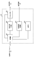
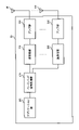
図1A及び1Bは、一実施形態に係るフレームタイミングの想定の一例を示す図である。図1Aは、異周波測定指示においてuseServingCellTimingForSyncが有効な場合の想定を示す。図1Aの場合、UEはサービングセル(セルA)と、別のキャリアのセルB(異周波測定対象セル)と、のフレームタイミングが同期していると想定してもよい。なお、セルBのSFNについては不明であると想定してもよいし、セルAのSFNに基づいて決定できる(例えば、セルAのSFNと同じである)と想定してもよい。 1A and 1B are diagrams illustrating an example of frame timing assumptions according to one embodiment. FIG. 1A shows an assumption when useServingCellTimingForSync is valid in the inter-frequency measurement instruction. In the case of FIG. 1A, the UE may assume that the frame timings of the serving cell (cell A) and the cell B of another carrier (inter-frequency measurement target cell) are synchronized. Note that the SFN of cell B may be assumed to be unknown, or may be determined based on the SFN of cell A (eg, the same as the SFN of cell A).
図1Bは、異周波測定指示においてuseServingCellTimingForSyncが有効でない(含まれない)場合の想定を示す。図1Bの場合、UEはサービングセル(セルA)と、別のキャリアのセルB(異周波測定対象セル)と、のフレームタイミングが同期しているとは想定しない(又は、想定できない、想定してはいけない)。 FIG. 1B shows an assumption when useServingCellTimingForSync is not valid (not included) in the inter-frequency measurement instruction. In the case of FIG. 1B, the UE does not assume that the frame timing of the serving cell (cell A) and another carrier's cell B (inter-frequency measurement target cell) are synchronized (or cannot be assumed, assumed Do not).
UEは、異周波測定指示においてuseServingCellTimingForSyncが有効な場合、測定対象周波数のセル間フレームタイミングは同期していると想定してもよい。この場合、UEは、キャリア間(例えば、接続中サービングセルのキャリアと測定対象周波数キャリアの間)の同期については想定しなくてもよい。また、この場合、UEは、測定対象周波数の少なくとも1つのセルについてSSBインデックスを取得してハーフフレームタイミング(又はフレームタイミング)が分かれば、当該1つのセルのSSBインデックス及び/又はハーフフレームタイミングに基づいて他のセルのSSBインデックスを決定することができる。 When useServingCellTimingForSync is valid in the inter-frequency measurement instruction, the UE may assume that the inter-cell frame timing of the measurement target frequency is synchronized. In this case, the UE may not assume synchronization between carriers (eg, between the carrier of the serving cell being connected and the frequency carrier under measurement). Also, in this case, if the UE acquires the SSB index for at least one cell of the frequency to be measured and the half-frame timing (or frame timing) is known, the SSB index and / or half-frame timing of the one cell can determine the SSB index of another cell.
一実施形態においては、useServingCellTimingForSyncは、異周波測定において、PBCHを復号するか否かに関する情報として用いられてもよい。 In one embodiment, useServingCellTimingForSync may be used as information regarding whether to decode PBCH in inter-frequency measurement.
例えば、UEは、異周波測定指示においてuseServingCellTimingForSyncが有効な場合、測定対象周波数のセルにおいてPBCHを復号しなくてもよい。なお、復号は、受信、検出などで読み替えられてもよい。PBCHを復号しないことは、PBCHを無視することを意味してもよい。 For example, when useServingCellTimingForSync is valid in the inter-frequency measurement instruction, the UE does not have to decode PBCH in the cell of the measurement target frequency. Note that decoding may be replaced with reception, detection, or the like. Not decoding the PBCH may mean ignoring the PBCH.
一実施形態においては、useServingCellTimingForSyncは、異周波測定において、SFNが同期(一致)するか否かに関する情報として用いられてもよい。 In one embodiment, useServingCellTimingForSync may be used as information regarding whether or not SFNs are synchronized (matched) in inter-frequency measurements.
例えば、UEは、異周波測定指示においてuseServingCellTimingForSyncが有効な場合、接続中サービングセルのSFNと測定対象キャリア(及び/又はセル)のSFNとが同期(一致)すると判断してもよい。 For example, when useServingCellTimingForSync is valid in the inter-frequency measurement instruction, the UE may determine that the SFN of the currently connected serving cell and the SFN of the carrier (and/or cell) to be measured synchronize (match).
以上説明した一実施形態によれば、異周波測定において、測定対象セルのPBCHの復号を省略できるため、通信スループットの低減を抑制できる。 According to the embodiment described above, decoding of the PBCH of the cell to be measured can be omitted in the inter-frequency measurement, so reduction in communication throughput can be suppressed.
<変形例>
上述の実施形態においては、UEは、異周波測定指示に含まれるuseServingCellTimingForSyncに基づいて同期の想定を判断したが、別の情報に基づいて同期の想定を判断してもよい。 <Modification>
In the above-described embodiment, the UE determines synchronization assumptions based on useServingCellTimingForSync included in the inter-frequency measurement instruction, but may determine synchronization assumptions based on other information.
例えば、異周波測定においてフレームタイミング同期を想定するか否か(又は想定してよいこと)に関する情報が、基地局からUEに対して明示的に通知されてもよい。UEは、当該情報が通知された場合、異周波測定において、サービングセルのフレームタイミングを、測定対象セルから送信されるSSBのインデックスを導出するために用いてもよい。 For example, the base station may explicitly notify the UE of information regarding whether or not to assume frame timing synchronization in inter-frequency measurement (or that it may be assumed). When the information is notified, the UE may use the frame timing of the serving cell in the inter-frequency measurement to derive the index of the SSB transmitted from the measurement target cell.
例えば、異周波測定においてPBCHを復号するか否か(又は復号しなくてよいこと)に関する情報が、基地局からUEに対して明示的に通知されてもよい。UEは、当該情報が通知された場合、異周波測定において、測定対象セルにおいてPBCHを復号しなくてもよい。 For example, the base station may explicitly notify the UE of information on whether or not to decode the PBCH in inter-frequency measurement (or that it does not need to be decoded). When the information is notified, the UE does not have to decode the PBCH in the measurement target cell in the inter-frequency measurement.
例えば、異周波測定においてSFN同期を想定するか否か(又は想定してよいこと)に関する情報が、基地局からUEに対して明示的に通知されてもよい。UEは、当該情報が通知された場合、異周波測定において、接続中サービングセルのSFNと測定対象セルのSFNとが同期(一致)すると判断してもよい。 For example, the base station may explicitly notify the UE of information regarding whether or not to assume SFN synchronization in inter-frequency measurement (or that it may be assumed). When the information is notified, the UE may determine that the SFN of the currently connected serving cell and the SFN of the measurement target cell are synchronized (matched) in inter-frequency measurement.
これらの情報は、上位レイヤシグナリング(RRCシグナリング、SIBなど)、物理レイヤシグナリング(DCIなど)又はこれらの組み合わせを用いて基地局から通知(設定)されてもよい。なお、これらの情報のうち少なくとも1つは、異周波測定指示に含まれて通知されてもよいし、異周波測定指示とは別のタイミングで通知されてもよい。 These pieces of information may be reported (configured) from the base station using higher layer signaling (RRC signaling, SIB, etc.), physical layer signaling (DCI, etc.), or a combination thereof. At least one of these pieces of information may be included in the different frequency measurement instruction and notified, or may be notified at a timing different from the different frequency measurement instruction.
なお、UEは、あるセルと他のセルが同期すると想定する場合、これらのフレームタイミングが同期(一致)すると想定してもよいし、SFNが同期(一致)すると想定してもよい。また、UEは、サービングセルと測定対象セルが同期すると想定する場合、当該サービングセルのフレームタイミングを当該測定対象セルから送信されるSSBのインデックスを導出するために用いてもよいし、当該測定対象セルにおいてPBCHを復号しなくてもよい。 Note that when assuming that one cell and another cell are synchronized, the UE may assume that their frame timings are synchronized (matched), or that their SFNs are synchronized (matched). Further, when the UE assumes that the serving cell and the measurement target cell are synchronized, the frame timing of the serving cell may be used to derive the index of the SSB transmitted from the measurement target cell. PBCH may not be decoded.
また、UEは、接続中のサービングセル(例えば、PCell、PSCell)及び測定対象セルの一方又は両方がTDDバンドに属する場合、当該サービングセルと測定対象セルが同期すると想定してもよい。 The UE may also assume that if one or both of the connected serving cell (eg, PCell, PSCell) and the measured cell belong to the TDD band, the serving cell and the measured cell are synchronized.
UEは、接続中のサービングセル及び測定対象セルの一方又は両方がTDDバンドに属し、かつuseServingCellTimingForSyncが有効な場合、当該サービングセルと測定対象セルのフレームタイミングが同期し、これらのSFNが同期すると想定してもよい。UEは、接続中のサービングセル及び測定対象セルの一方又は両方がTDDバンドに属し、かつuseServingCellTimingForSyncが有効でない場合、当該サービングセルと測定対象セルのフレームタイミングが同期し、これらのSFNは同期しないと想定してもよい。 The UE assumes that when one or both of the connected serving cell and the cell to be measured belong to the TDD band and useServingCellTimingForSync is enabled, the frame timings of the serving cell and the cell to be measured are synchronized, and these SFNs are synchronized. good too. The UE assumes that if one or both of the connected serving cell and the cell under measurement belong to the TDD band and useServingCellTimingForSync is not enabled, the frame timings of the serving cell and the cell under measurement are synchronized, and their SFNs are not synchronized. may
UEは、接続中のサービングセル及び測定対象セルの一方又は両方が周波数分割複信(FDD:Frequency Division Duplex)バンドに属し、かつuseServingCellTimingForSyncが有効な場合、当該サービングセルと測定対象セルのフレームタイミングが同期し、これらのSFNは同期しないと想定してもよい。UEは、接続中のサービングセル及び測定対象セルの一方又は両方がFDDバンドに属し、かつuseServingCellTimingForSyncが有効でない場合、当該サービングセルと測定対象セルのフレームタイミングもSFNも同期しないと想定してもよい。 UE, one or both of the connected serving cell and the cell to be measured belongs to the frequency division duplex (FDD: Frequency Division Duplex) band, and if useServingCellTimingForSync is valid, the frame timing of the serving cell and the cell to be measured is synchronized , one may assume that these SFNs are not synchronized. The UE may assume that if one or both of the connected serving and measured cells belong to the FDD band and useServingCellTimingForSync is not enabled, neither the frame timing nor the SFN of the serving and measured cells are synchronized.
また、UEは、接続中のサービングセル(例えば、PCell、PSCell)及び測定対象セルの一方又は両方の周波数バンドに基づいて、当該サービングセル及び/又は測定対象セルに関する同期の想定を変えてもよい。 Also, the UE may change its synchronization assumptions for the serving cell (e.g., PCell, PSCell) and/or the measured cell to which it is connected, based on the frequency band of the serving cell and/or the measured cell.
例えば、UEは、接続中のサービングセル(例えば、PCell、PSCell)及び測定対象セルの両方が同じ周波数バンド(例えば、FR1)に属し、かつuseServingCellTimingForSyncが有効な場合、キャリア間同期(ひいては、接続中のサービングセル及び測定対象セルの同期)を想定してもよい。若しくは、UEは、接続中のサービングセル及び測定対象セルの両方が同じ周波数バンドに属する場合にはuseServingCellTimingForSyncが有効な場合であっても、キャリア間同期は想定しなくてもよく、測定対象周波数のセル間の同期は想定してもよい。 For example, the UE, both the serving cell being connected (e.g., PCell, PSCell) and the cell to be measured belong to the same frequency band (e.g., FR1), and if useServingCellTimingForSync is enabled, inter-carrier synchronization (and thus connecting synchronization of the serving cell and the cell under measurement) may be assumed. Alternatively, the UE, even if useServingCellTimingForSync is valid when both the serving cell being connected and the cell to be measured belong to the same frequency band, do not assume inter-carrier synchronization, the cell of the frequency to be measured Synchronization between may be assumed.
UEは、接続中のサービングセル(例えば、PCell、PSCell)及び測定対象セルの両方が異なる周波数バンドに属する(例えば、サービングセルがFR1、測定対象セルがFR2に属する)場合には、useServingCellTimingForSyncが有効な場合であっても、キャリア間同期は想定しなくてもよく、測定対象周波数のセル間の同期は想定してもよい。若しくは、UEは、接続中のサービングセル)及び測定対象セルの両方が異なる周波数バンドに属し、かつuseServingCellTimingForSyncが有効な場合、キャリア間同期(ひいては、接続中のサービングセル及び測定対象セルの同期)を想定してもよい。 If the serving cell being connected (e.g., PCell, PSCell) and the cell to be measured belong to different frequency bands (e.g., the serving cell belongs to FR1 and the cell to be measured belongs to FR2), useServingCellTimingForSync is enabled. However, inter-carrier synchronization may not be assumed, and inter-cell synchronization of the measurement target frequency may be assumed. Alternatively, the UE assumes inter-carrier synchronization (and thus synchronization of the serving cell being connected and the cell being measured) when both the serving cell being connected and the cell being measured belong to different frequency bands and useServingCellTimingForSync is enabled. may
なお、1つの周波数レンジに複数のキャリアが含まれ、1つのキャリアに複数のセルが含まれる構成について説明したが、本開示において、周波数レンジ、セル、サービングセル、キャリア、バンド及びCCは、相互に読み替えられてもよい。 Although a configuration in which one frequency range includes multiple carriers and one carrier includes multiple cells has been described, in the present disclosure, frequency ranges, cells, serving cells, carriers, bands, and CCs are mutually It may be reread.
なお、本開示において、「異周波測定」は、「ハンドオーバー」で読み替えられてもよく、この場合、「測定対象」は「ターゲット」で読み替えられてもよい。 In the present disclosure, "measurement of different frequencies" may be read as "handover", and in this case, "measurement target" may be read as "target".
(無線通信システム)
以下、本開示の一実施形態に係る無線通信システムの構成について説明する。この無線通信システムでは、本開示の上記各実施形態に係る無線通信方法のいずれか又はこれらの組み合わせを用いて通信が行われる。(wireless communication system)
A configuration of a wireless communication system according to an embodiment of the present disclosure will be described below. In this radio communication system, communication is performed using any one of the radio communication methods according to the above embodiments of the present disclosure or a combination thereof.
図2は、一実施形態に係る無線通信システムの概略構成の一例を示す図である。無線通信システム1では、LTEシステムのシステム帯域幅(例えば、20MHz)を1単位とする複数の基本周波数ブロック(コンポーネントキャリア)を一体としたキャリアアグリゲーション(CA)及び/又はデュアルコネクティビティ(DC)を適用することができる。
FIG. 2 is a diagram illustrating an example of a schematic configuration of a radio communication system according to an embodiment. In the
なお、無線通信システム1は、LTE(Long Term Evolution)、LTE-A(LTE-Advanced)、LTE-B(LTE-Beyond)、SUPER 3G、IMT-Advanced、4G(4th generation mobile communication system)、5G(5th generation mobile communication system)、NR(New Radio)、FRA(Future Radio Access)、New-RAT(Radio Access Technology)などと呼ばれてもよいし、これらを実現するシステムと呼ばれてもよい。
The
無線通信システム1は、比較的カバレッジの広いマクロセルC1を形成する無線基地局11と、マクロセルC1内に配置され、マクロセルC1よりも狭いスモールセルC2を形成する無線基地局12(12a-12c)と、を備えている。また、マクロセルC1及び各スモールセルC2には、ユーザ端末20が配置されている。各セル及びユーザ端末20の配置、数などは、図に示す態様に限定されない。
A
ユーザ端末20は、無線基地局11及び無線基地局12の双方に接続することができる。ユーザ端末20は、マクロセルC1及びスモールセルC2を、CA又はDCを用いて同時に使用することが想定される。また、ユーザ端末20は、複数のセル(CC)を用いてCA又はDCを適用してもよい。
A
ユーザ端末20と無線基地局11との間は、相対的に低い周波数帯域(例えば、2GHz)で帯域幅が狭いキャリア(既存キャリア、legacy carrierなどとも呼ばれる)を用いて通信を行うことができる。一方、ユーザ端末20と無線基地局12との間は、相対的に高い周波数帯域(例えば、3.5GHz、5GHzなど)で帯域幅が広いキャリアが用いられてもよいし、無線基地局11との間と同じキャリアが用いられてもよい。なお、各無線基地局が利用する周波数帯域の構成はこれに限られない。
Communication between the
また、ユーザ端末20は、各セルで、時分割複信(TDD:Time Division Duplex)及び/又は周波数分割複信(FDD:Frequency Division Duplex)を用いて通信を行うことができる。また、各セル(キャリア)では、単一のニューメロロジーが適用されてもよいし、複数の異なるニューメロロジーが適用されてもよい。
Also, the
ニューメロロジーとは、ある信号及び/又はチャネルの送信及び/又は受信に適用される通信パラメータであってもよく、例えば、サブキャリア間隔、帯域幅、シンボル長、サイクリックプレフィックス長、サブフレーム長、TTI長、TTIあたりのシンボル数、無線フレーム構成、送受信機が周波数領域で行う特定のフィルタリング処理、送受信機が時間領域で行う特定のウィンドウイング処理などの少なくとも1つを示してもよい。例えば、ある物理チャネルについて、構成するOFDMシンボルのサブキャリア間隔が異なる場合及び/又はOFDMシンボル数が異なる場合には、ニューメロロジーが異なると称されてもよい。 A numerology may be a communication parameter that applies to the transmission and/or reception of a certain signal and/or channel, e.g. subcarrier spacing, bandwidth, symbol length, cyclic prefix length, subframe length , TTI length, number of symbols per TTI, radio frame structure, certain filtering operations performed by the transceiver in the frequency domain, certain windowing operations performed by the transceiver in the time domain, and/or the like. For example, if a physical channel has different subcarrier spacing and/or different numbers of OFDM symbols, it may be said to have different numerologies.
無線基地局11と無線基地局12との間(又は、2つの無線基地局12間)は、有線(例えば、CPRI(Common Public Radio Interface)に準拠した光ファイバ、X2インターフェースなど)又は無線によって接続されてもよい。
The
無線基地局11及び各無線基地局12は、それぞれ上位局装置30に接続され、上位局装置30を介してコアネットワーク40に接続される。なお、上位局装置30には、例えば、アクセスゲートウェイ装置、無線ネットワークコントローラ(RNC)、モビリティマネジメントエンティティ(MME)などが含まれるが、これに限定されない。また、各無線基地局12は、無線基地局11を介して上位局装置30に接続されてもよい。
The
なお、無線基地局11は、相対的に広いカバレッジを有する無線基地局であり、マクロ基地局、集約ノード、eNB(eNodeB)、送受信ポイント、などと呼ばれてもよい。また、無線基地局12は、局所的なカバレッジを有する無線基地局であり、スモール基地局、マイクロ基地局、ピコ基地局、フェムト基地局、HeNB(Home eNodeB)、RRH(Remote Radio Head)、送受信ポイントなどと呼ばれてもよい。以下、無線基地局11及び12を区別しない場合は、無線基地局10と総称する。
Note that the
各ユーザ端末20は、LTE、LTE-Aなどの各種通信方式に対応した端末であり、移動通信端末(移動局)だけでなく固定通信端末(固定局)を含んでもよい。
Each
無線通信システム1においては、無線アクセス方式として、下りリンクに直交周波数分割多元接続(OFDMA:Orthogonal Frequency Division Multiple Access)が適用され、上りリンクにシングルキャリア-周波数分割多元接続(SC-FDMA:Single Carrier Frequency Division Multiple Access)及び/又はOFDMAが適用される。
In the
OFDMAは、周波数帯域を複数の狭い周波数帯域(サブキャリア)に分割し、各サブキャリアにデータをマッピングして通信を行うマルチキャリア伝送方式である。SC-FDMAは、システム帯域幅を端末ごとに1つ又は連続したリソースブロックによって構成される帯域に分割し、複数の端末が互いに異なる帯域を用いることで、端末間の干渉を低減するシングルキャリア伝送方式である。なお、上り及び下りの無線アクセス方式は、これらの組み合わせに限らず、他の無線アクセス方式が用いられてもよい。 OFDMA is a multi-carrier transmission scheme in which a frequency band is divided into a plurality of narrow frequency bands (subcarriers) and data is mapped to each subcarrier for communication. SC-FDMA divides the system bandwidth into bands composed of one or continuous resource blocks for each terminal, and multiple terminals use different bands to reduce interference between terminals Single carrier transmission method. Note that the uplink and downlink radio access schemes are not limited to these combinations, and other radio access schemes may be used.
無線通信システム1では、下りリンクのチャネルとして、各ユーザ端末20で共有される下り共有チャネル(PDSCH:Physical Downlink Shared Channel)、ブロードキャストチャネル(PBCH:Physical Broadcast Channel)、下りL1/L2制御チャネルなどが用いられる。PDSCHによって、ユーザデータ、上位レイヤ制御情報、SIB(System Information Block)などが伝送される。また、PBCHによって、MIB(Master Information Block)が伝送される。
In the
下りL1/L2制御チャネルは、PDCCH(Physical Downlink Control Channel)、EPDCCH(Enhanced Physical Downlink Control Channel)、PCFICH(Physical Control Format Indicator Channel)、PHICH(Physical Hybrid-ARQ Indicator Channel)などを含む。PDCCHによって、PDSCH及び/又はPUSCHのスケジューリング情報を含む下り制御情報(DCI:Downlink Control Information)などが伝送される。 The downlink L1/L2 control channel includes PDCCH (Physical Downlink Control Channel), EPDCCH (Enhanced Physical Downlink Control Channel), PCFICH (Physical Control Format Indicator Channel), PHICH (Physical Hybrid-ARQ Indicator Channel), and the like. Downlink control information (DCI: Downlink Control Information) including PDSCH and/or PUSCH scheduling information and the like are transmitted by the PDCCH.
なお、DLデータ受信をスケジューリングするDCIは、DLアサインメントと呼ばれてもよいし、ULデータ送信をスケジューリングするDCIは、ULグラントと呼ばれてもよい。 Note that a DCI that schedules DL data reception may be called a DL assignment, and a DCI that schedules UL data transmission may be called a UL grant.
PCFICHによって、PDCCHに用いるOFDMシンボル数が伝送される。PHICHによって、PUSCHに対するHARQ(Hybrid Automatic Repeat reQuest)の送達確認情報(例えば、再送制御情報、HARQ-ACK、ACK/NACKなどともいう)が伝送される。EPDCCHは、PDSCH(下り共有データチャネル)と周波数分割多重され、PDCCHと同様にDCIなどの伝送に用いられる。 PCFICH carries the number of OFDM symbols used for PDCCH. The PHICH transmits HARQ (Hybrid Automatic Repeat reQuest) acknowledgment information (for example, retransmission control information, HARQ-ACK, ACK/NACK, etc.) for PUSCH. EPDCCH is frequency-division multiplexed with PDSCH (downlink shared data channel), and is used for transmission of DCI and the like like PDCCH.
無線通信システム1では、上りリンクのチャネルとして、各ユーザ端末20で共有される上り共有チャネル(PUSCH:Physical Uplink Shared Channel)、上り制御チャネル(PUCCH:Physical Uplink Control Channel)、ランダムアクセスチャネル(PRACH:Physical Random Access Channel)などが用いられる。PUSCHによって、ユーザデータ、上位レイヤ制御情報などが伝送される。また、PUCCHによって、下りリンクの無線品質情報(CQI:Channel Quality Indicator)、送達確認情報、スケジューリングリクエスト(SR:Scheduling Request)などが伝送される。PRACHによって、セルとの接続確立のためのランダムアクセスプリアンブルが伝送される。
In the
無線通信システム1では、下り参照信号として、セル固有参照信号(CRS:Cell-specific Reference Signal)、チャネル状態情報参照信号(CSI-RS:Channel State Information-Reference Signal)、復調用参照信号(DMRS:DeModulation Reference Signal)、位置決定参照信号(PRS:Positioning Reference Signal)などが伝送される。また、無線通信システム1では、上り参照信号として、測定用参照信号(SRS:Sounding Reference Signal)、復調用参照信号(DMRS)などが伝送される。なお、DMRSはユーザ端末固有参照信号(UE-specific Reference Signal)と呼ばれてもよい。また、伝送される参照信号は、これらに限られない。
In the
(無線基地局)
図3は、一実施形態に係る無線基地局の全体構成の一例を示す図である。無線基地局10は、複数の送受信アンテナ101と、アンプ部102と、送受信部103と、ベースバンド信号処理部104と、呼処理部105と、伝送路インターフェース106と、を備えている。なお、送受信アンテナ101、アンプ部102、送受信部103は、それぞれ1つ以上を含むように構成されればよい。(radio base station)
FIG. 3 is a diagram showing an example of the overall configuration of a radio base station according to one embodiment. The
下りリンクによって無線基地局10からユーザ端末20に送信されるユーザデータは、上位局装置30から伝送路インターフェース106を介してベースバンド信号処理部104に入力される。
User data transmitted from the
ベースバンド信号処理部104では、ユーザデータに関して、PDCP(Packet Data Convergence Protocol)レイヤの処理、ユーザデータの分割・結合、RLC(Radio Link Control)再送制御などのRLCレイヤの送信処理、MAC(Medium Access Control)再送制御(例えば、HARQの送信処理)、スケジューリング、伝送フォーマット選択、チャネル符号化、逆高速フーリエ変換(IFFT:Inverse Fast Fourier Transform)処理、プリコーディング処理などの送信処理が行われて送受信部103に転送される。また、下り制御信号に関しても、チャネル符号化、逆高速フーリエ変換などの送信処理が行われて、送受信部103に転送される。
In the baseband
送受信部103は、ベースバンド信号処理部104からアンテナごとにプリコーディングして出力されたベースバンド信号を無線周波数帯に変換して送信する。送受信部103で周波数変換された無線周波数信号は、アンプ部102によって増幅され、送受信アンテナ101から送信される。送受信部103は、本開示に係る技術分野での共通認識に基づいて説明されるトランスミッター/レシーバー、送受信回路又は送受信装置から構成することができる。なお、送受信部103は、一体の送受信部として構成されてもよいし、送信部及び受信部から構成されてもよい。
Transmitting/receiving
一方、上り信号については、送受信アンテナ101で受信された無線周波数信号がアンプ部102で増幅される。送受信部103はアンプ部102で増幅された上り信号を受信する。送受信部103は、受信信号をベースバンド信号に周波数変換して、ベースバンド信号処理部104に出力する。
On the other hand, as for the uplink signal, the radio frequency signal received by the transmitting/receiving
ベースバンド信号処理部104では、入力された上り信号に含まれるユーザデータに対して、高速フーリエ変換(FFT:Fast Fourier Transform)処理、逆離散フーリエ変換(IDFT:Inverse Discrete Fourier Transform)処理、誤り訂正復号、MAC再送制御の受信処理、RLCレイヤ及びPDCPレイヤの受信処理がなされ、伝送路インターフェース106を介して上位局装置30に転送される。呼処理部105は、通信チャネルの呼処理(設定、解放など)、無線基地局10の状態管理、無線リソースの管理などを行う。
The baseband
伝送路インターフェース106は、所定のインターフェースを介して、上位局装置30と信号を送受信する。また、伝送路インターフェース106は、基地局間インターフェース(例えば、CPRI(Common Public Radio Interface)に準拠した光ファイバ、X2インターフェース)を介して他の無線基地局10と信号を送受信(バックホールシグナリング)してもよい。
The
なお、送受信部103は、アナログビームフォーミングを実施するアナログビームフォーミング部をさらに有してもよい。アナログビームフォーミング部は、本発明に係る技術分野での共通認識に基づいて説明されるアナログビームフォーミング回路(例えば、位相シフタ、位相シフト回路)又はアナログビームフォーミング装置(例えば、位相シフト器)から構成してもよい。また、送受信アンテナ101は、例えばアレーアンテナによって構成してもよい。
Note that the transmitting/receiving
送受信部103は、SMTCが設定されるキャリアに含まれるセルにおいて、データを送信及び/又は受信する。送受信部103は、同周波測定及び/又は異周波測定に関する情報などを、ユーザ端末20に対して送信してもよい。
Transmitting/receiving
図4は、本開示の一実施形態に係る無線基地局の機能構成の一例を示す図である。なお、本例では、本実施形態における特徴部分の機能ブロックを主に示しており、無線基地局10は、無線通信に必要な他の機能ブロックも有すると想定されてもよい。
FIG. 4 is a diagram illustrating an example of a functional configuration of a radio base station according to an embodiment of the present disclosure; Note that this example mainly shows the functional blocks that characterize the present embodiment, and it may be assumed that the
ベースバンド信号処理部104は、制御部(スケジューラ)301と、送信信号生成部302と、マッピング部303と、受信信号処理部304と、測定部305と、を少なくとも備えている。なお、これらの構成は、無線基地局10に含まれていればよく、一部又は全部の構成がベースバンド信号処理部104に含まれなくてもよい。
The baseband
制御部(スケジューラ)301は、無線基地局10全体の制御を実施する。制御部301は、本開示に係る技術分野での共通認識に基づいて説明されるコントローラ、制御回路又は制御装置から構成することができる。
A control unit (scheduler) 301 controls the entire
制御部301は、例えば、送信信号生成部302における信号の生成、マッピング部303における信号の割り当てなどを制御する。また、制御部301は、受信信号処理部304における信号の受信処理、測定部305における信号の測定などを制御する。
The
制御部301は、システム情報、下りデータ信号(例えば、PDSCHで送信される信号)、下り制御信号(例えば、PDCCH及び/又はEPDCCHで送信される信号。送達確認情報など)のスケジューリング(例えば、リソース割り当て)を制御する。また、制御部301は、上りデータ信号に対する再送制御の要否を判定した結果などに基づいて、下り制御信号、下りデータ信号などの生成を制御する。
制御部301は、同期信号(例えば、PSS(Primary Synchronization Signal)/SSS(Secondary Synchronization Signal))、下り参照信号(例えば、CRS、CSI-RS、DMRS)などのスケジューリングの制御を行う。
The
制御部301は、上りデータ信号(例えば、PUSCHで送信される信号)、上り制御信号(例えば、PUCCH及び/又はPUSCHで送信される信号。送達確認情報など)、ランダムアクセスプリアンブル(例えば、PRACHで送信される信号)、上り参照信号などのスケジューリングを制御する。
The
制御部301は、ベースバンド信号処理部104におけるデジタルBF(例えば、プリコーディング)及び/又は送受信部103におけるアナログBF(例えば、位相回転)を用いて、送信ビーム及び/又は受信ビームを形成する制御を行ってもよい。制御部301は、下り伝搬路情報、上り伝搬路情報などに基づいて、ビームを形成する制御を行ってもよい。これらの伝搬路情報は、受信信号処理部304及び/又は測定部305から取得されてもよい。
The
制御部301は、第1のキャリアにユーザ端末20のサービングセルが含まれる場合に、第2のキャリアにおける異周波測定を指示する測定指示を当該ユーザ端末20に送信する制御を行ってもよい。
When the serving cell of the
制御部301は、上記測定指示に、測定対象セルにおけるSSBに関する処理を制御するための特定の情報を含めるように制御してもよい。
The
送信信号生成部302は、制御部301からの指示に基づいて、下り信号(下り制御信号、下りデータ信号、下り参照信号など)を生成して、マッピング部303に出力する。送信信号生成部302は、本開示に係る技術分野での共通認識に基づいて説明される信号生成器、信号生成回路又は信号生成装置から構成することができる。
Transmission
送信信号生成部302は、例えば、制御部301からの指示に基づいて、下りデータの割り当て情報を通知するDLアサインメント及び/又は上りデータの割り当て情報を通知するULグラントを生成する。DLアサインメント及びULグラントは、いずれもDCIであり、DCIフォーマットに従う。また、下りデータ信号には、各ユーザ端末20からのチャネル状態情報(CSI:Channel State Information)などに基づいて決定された符号化率、変調方式などに従って符号化処理、変調処理が行われる。
The transmission
マッピング部303は、制御部301からの指示に基づいて、送信信号生成部302で生成された下り信号を、所定の無線リソースにマッピングして、送受信部103に出力する。マッピング部303は、本開示に係る技術分野での共通認識に基づいて説明されるマッパー、マッピング回路又はマッピング装置から構成することができる。
Based on an instruction from
受信信号処理部304は、送受信部103から入力された受信信号に対して、受信処理(例えば、デマッピング、復調、復号など)を行う。ここで、受信信号は、例えば、ユーザ端末20から送信される上り信号(上り制御信号、上りデータ信号、上り参照信号など)である。受信信号処理部304は、本開示に係る技術分野での共通認識に基づいて説明される信号処理器、信号処理回路又は信号処理装置から構成することができる。
Received
受信信号処理部304は、受信処理によって復号された情報を制御部301に出力する。例えば、HARQ-ACKを含むPUCCHを受信した場合、HARQ-ACKを制御部301に出力する。また、受信信号処理部304は、受信信号及び/又は受信処理後の信号を、測定部305に出力する。
Received
測定部305は、受信した信号に関する測定を実施する。測定部305は、本開示に係る技術分野での共通認識に基づいて説明される測定器、測定回路又は測定装置から構成することができる。
A
例えば、測定部305は、受信した信号に基づいて、RRM(Radio Resource Management)測定、CSI(Channel State Information)測定などを行ってもよい。測定部305は、受信電力(例えば、RSRP(Reference Signal Received Power))、受信品質(例えば、RSRQ(Reference Signal Received Quality)、SINR(Signal to Interference plus Noise Ratio)、SNR(Signal to Noise Ratio))、信号強度(例えば、RSSI(Received Signal Strength Indicator))、伝搬路情報(例えば、CSI)などについて測定してもよい。測定結果は、制御部301に出力されてもよい。
For example, the
(ユーザ端末)
図5は、一実施形態に係るユーザ端末の全体構成の一例を示す図である。ユーザ端末20は、複数の送受信アンテナ201と、アンプ部202と、送受信部203と、ベースバンド信号処理部204と、アプリケーション部205と、を備えている。なお、送受信アンテナ201、アンプ部202、送受信部203は、それぞれ1つ以上を含むように構成されればよい。(user terminal)
FIG. 5 is a diagram illustrating an example of the overall configuration of a user terminal according to one embodiment. The
送受信アンテナ201で受信された無線周波数信号は、アンプ部202で増幅される。送受信部203は、アンプ部202で増幅された下り信号を受信する。送受信部203は、受信信号をベースバンド信号に周波数変換して、ベースバンド信号処理部204に出力する。送受信部203は、本開示に係る技術分野での共通認識に基づいて説明されるトランスミッター/レシーバー、送受信回路又は送受信装置から構成することができる。なお、送受信部203は、一体の送受信部として構成されてもよいし、送信部及び受信部から構成されてもよい。
A radio frequency signal received by the transmitting/receiving
ベースバンド信号処理部204は、入力されたベースバンド信号に対して、FFT処理、誤り訂正復号、再送制御の受信処理などを行う。下りリンクのユーザデータは、アプリケーション部205に転送される。アプリケーション部205は、物理レイヤ及びMACレイヤより上位のレイヤに関する処理などを行う。また、下りリンクのデータのうち、ブロードキャスト情報もアプリケーション部205に転送されてもよい。
The baseband
一方、上りリンクのユーザデータについては、アプリケーション部205からベースバンド信号処理部204に入力される。ベースバンド信号処理部204では、再送制御の送信処理(例えば、HARQの送信処理)、チャネル符号化、プリコーディング、離散フーリエ変換(DFT:Discrete Fourier Transform)処理、IFFT処理などが行われて送受信部203に転送される。
On the other hand, uplink user data is input from the
送受信部203は、ベースバンド信号処理部204から出力されたベースバンド信号を無線周波数帯に変換して送信する。送受信部203で周波数変換された無線周波数信号は、アンプ部202によって増幅され、送受信アンテナ201から送信される。
The transmitting/receiving
なお、送受信部203は、アナログビームフォーミングを実施するアナログビームフォーミング部をさらに有してもよい。アナログビームフォーミング部は、本発明に係る技術分野での共通認識に基づいて説明されるアナログビームフォーミング回路(例えば、位相シフタ、位相シフト回路)又はアナログビームフォーミング装置(例えば、位相シフト器)から構成してもよい。また、送受信アンテナ201は、例えばアレーアンテナによって構成してもよい。
Note that the transmitting/receiving
送受信部203は、SMTCが設定されるキャリアに含まれるセルにおいて、データを送信及び/又は受信する。送受信部203は、同周波測定及び/又は異周波測定に関する情報などを、無線基地局10から受信してもよい。例えば、送受信部203は、第1のキャリアにサービングセルが含まれる場合に、第2のキャリアにおける異周波測定を指示する測定指示を受信してもよい。
Transmitting/receiving
図6は、一実施形態に係るユーザ端末の機能構成の一例を示す図である。なお、本例においては、本実施形態における特徴部分の機能ブロックを主に示しており、ユーザ端末20は、無線通信に必要な他の機能ブロックも有すると想定されてもよい。
FIG. 6 is a diagram illustrating an example of a functional configuration of a user terminal according to one embodiment; Note that this example mainly shows the functional blocks of the characteristic portions of the present embodiment, and it may be assumed that the
ユーザ端末20が有するベースバンド信号処理部204は、制御部401と、送信信号生成部402と、マッピング部403と、受信信号処理部404と、測定部405と、を少なくとも備えている。なお、これらの構成は、ユーザ端末20に含まれていればよく、一部又は全部の構成がベースバンド信号処理部204に含まれなくてもよい。
The baseband
制御部401は、ユーザ端末20全体の制御を実施する。制御部401は、本開示に係る技術分野での共通認識に基づいて説明されるコントローラ、制御回路又は制御装置から構成することができる。
The
制御部401は、例えば、送信信号生成部402における信号の生成、マッピング部403における信号の割り当てなどを制御する。また、制御部401は、受信信号処理部404における信号の受信処理、測定部405における信号の測定などを制御する。
The
制御部401は、無線基地局10から送信された下り制御信号及び下りデータ信号を、受信信号処理部404から取得する。制御部401は、下り制御信号及び/又は下りデータ信号に対する再送制御の要否を判定した結果などに基づいて、上り制御信号及び/又は上りデータ信号の生成を制御する。
The
制御部401は、ベースバンド信号処理部204におけるデジタルBF(例えば、プリコーディング)及び/又は送受信部203におけるアナログBF(例えば、位相回転)を用いて、送信ビーム及び/又は受信ビームを形成する制御を行ってもよい。制御部401は、下り伝搬路情報、上り伝搬路情報などに基づいて、ビームを形成する制御を行ってもよい。これらの伝搬路情報は、受信信号処理部404及び/又は測定部405から取得されてもよい。
The
制御部401は、第1のキャリアにサービングセルが含まれる場合に、受信信号処理部404から取得した測定指示に基づいて第2のキャリアにおける異周波測定を行う制御を行ってもよい。ここで、上記第2のキャリアは、上記第1のキャリアと異なるキャリアである。上記測定指示は、MeasObjectNR情報要素であってもよい。
When the serving cell is included in the first carrier, the
制御部401は、特定の情報が上記測定指示に含まれる場合に、当該特定の情報に基づいて、上記測定指示に対応する測定対象セルにおける同期信号ブロック(SSB:Synchronization Signal Block)に関する処理を制御してもよい。ここで、上記特定の情報は、隣接セルによって送信されるSSBのインデックスをサービングセルのタイミングに基づいて導出できるかを示す情報(useServingCellTimingForSync)であってもよいし、useServingCellTimingForSyncとは別の情報であってもよい。
When specific information is included in the measurement instruction, the
例えば、制御部401は、上記特定の情報が上記測定指示に含まれる場合に、上記第1のキャリアのサービングセルのフレームタイミングを用いて、上記第2のキャリアの測定対象セルのSSBインデックスを導出してもよい。
For example, when the specific information is included in the measurement instruction, the
制御部401は、上記特定の情報が上記測定指示に含まれる場合に、上記第2のキャリアの複数の測定対象セルのフレームタイミングが同期していると想定してもよい。
The
なお、「上記特定の情報が上記測定指示に含まれる」は、「上記特定の情報が通知される」などで読み替えられてもよい。つまり、上記特定の情報は上記測定指示に含まれず、別のシグナリングによって通知されてもよい。 Note that "the specific information is included in the measurement instruction" may be replaced with "the specific information is notified" or the like. That is, the specific information may not be included in the measurement indication and may be notified by another signaling.
また、制御部401は、無線基地局10から通知された各種情報を受信信号処理部404から取得した場合、当該情報に基づいて制御に用いるパラメータを更新してもよい。
Further, when various information notified from the
送信信号生成部402は、制御部401からの指示に基づいて、上り信号(上り制御信号、上りデータ信号、上り参照信号など)を生成して、マッピング部403に出力する。送信信号生成部402は、本開示に係る技術分野での共通認識に基づいて説明される信号生成器、信号生成回路又は信号生成装置から構成することができる。
Transmission
送信信号生成部402は、例えば、制御部401からの指示に基づいて、送達確認情報、チャネル状態情報(CSI)などに関する上り制御信号を生成する。また、送信信号生成部402は、制御部401からの指示に基づいて上りデータ信号を生成する。例えば、送信信号生成部402は、無線基地局10から通知される下り制御信号にULグラントが含まれている場合に、制御部401から上りデータ信号の生成を指示される。
The transmission
マッピング部403は、制御部401からの指示に基づいて、送信信号生成部402で生成された上り信号を無線リソースにマッピングして、送受信部203へ出力する。マッピング部403は、本開示に係る技術分野での共通認識に基づいて説明されるマッパー、マッピング回路又はマッピング装置から構成することができる。
受信信号処理部404は、送受信部203から入力された受信信号に対して、受信処理(例えば、デマッピング、復調、復号など)を行う。ここで、受信信号は、例えば、無線基地局10から送信される下り信号(下り制御信号、下りデータ信号、下り参照信号など)である。受信信号処理部404は、本開示に係る技術分野での共通認識に基づいて説明される信号処理器、信号処理回路又は信号処理装置から構成することができる。また、受信信号処理部404は、本開示に係る受信部を構成することができる。
Received
受信信号処理部404は、受信処理によって復号された情報を制御部401に出力する。受信信号処理部404は、例えば、ブロードキャスト情報、システム情報、RRCシグナリング、DCIなどを、制御部401に出力する。また、受信信号処理部404は、受信信号及び/又は受信処理後の信号を、測定部405に出力する。
Received
測定部405は、受信した信号に関する測定を実施する。例えば、測定部405は、第1のキャリア及び第2のキャリアの一方又は両方について、同周波測定及び/又は異周波測定を行ってもよい。測定部405は、第1のキャリアにサービングセルが含まれる場合に、受信信号処理部404から取得した測定指示に基づいて第2のキャリアにおける異周波測定を行ってもよい。測定部405は、本開示に係る技術分野での共通認識に基づいて説明される測定器、測定回路又は測定装置から構成することができる。
A
例えば、測定部405は、受信した信号に基づいて、RRM測定、CSI測定などを行ってもよい。測定部405は、受信電力(例えば、RSRP)、受信品質(例えば、RSRQ、SINR、SNR)、信号強度(例えば、RSSI)、伝搬路情報(例えば、CSI)などについて測定してもよい。測定結果は、制御部401に出力されてもよい。
For example,
(ハードウェア構成)
なお、上記実施形態の説明に用いたブロック図は、機能単位のブロックを示している。これらの機能ブロック(構成部)は、ハードウェア及び/又はソフトウェアの任意の組み合わせによって実現される。また、各機能ブロックの実現方法は特に限定されない。すなわち、各機能ブロックは、物理的及び/又は論理的に結合した1つの装置を用いて実現されてもよいし、物理的及び/又は論理的に分離した2つ以上の装置を直接的及び/又は間接的に(例えば、有線及び/又は無線を用いて)接続し、これら複数の装置を用いて実現されてもよい。(Hardware configuration)
It should be noted that the block diagrams used in the description of the above embodiments show blocks in units of functions. These functional blocks (components) are implemented by any combination of hardware and/or software. Also, the method of implementing each functional block is not particularly limited. That is, each functional block may be implemented using one device physically and/or logically coupled, or two or more devices physically and/or logically separated directly and/or or indirectly connected (eg, using wired and/or wireless) and implemented using these multiple devices.
例えば、本開示の一実施形態における無線基地局、ユーザ端末などは、本開示の無線通信方法の処理を行うコンピュータとして機能してもよい。図7は、一実施形態に係る無線基地局及びユーザ端末のハードウェア構成の一例を示す図である。上述の無線基地局10及びユーザ端末20は、物理的には、プロセッサ1001、メモリ1002、ストレージ1003、通信装置1004、入力装置1005、出力装置1006、バス1007などを含むコンピュータ装置として構成されてもよい。
For example, a radio base station, a user terminal, etc. according to an embodiment of the present disclosure may function as a computer that performs processing of the radio communication method of the present disclosure. FIG. 7 is a diagram illustrating an example of hardware configurations of a radio base station and a user terminal according to one embodiment. The
なお、以下の説明では、「装置」という文言は、回路、デバイス、ユニットなどに読み替えることができる。無線基地局10及びユーザ端末20のハードウェア構成は、図に示した各装置を1つ又は複数含むように構成されてもよいし、一部の装置を含まずに構成されてもよい。
Note that in the following description, the term "apparatus" can be read as a circuit, device, unit, or the like. The hardware configuration of the
例えば、プロセッサ1001は1つだけ図示されているが、複数のプロセッサがあってもよい。また、処理は、1のプロセッサによって実行されてもよいし、処理が同時に、逐次に、又はその他の手法を用いて、1以上のプロセッサによって実行されてもよい。なお、プロセッサ1001は、1以上のチップによって実装されてもよい。
For example, although only one
無線基地局10及びユーザ端末20における各機能は、例えば、プロセッサ1001、メモリ1002などのハードウェア上に所定のソフトウェア(プログラム)を読み込ませることによって、プロセッサ1001が演算を行い、通信装置1004を介する通信を制御したり、メモリ1002及びストレージ1003におけるデータの読み出し及び/又は書き込みを制御したりすることによって実現される。
Each function in the
プロセッサ1001は、例えば、オペレーティングシステムを動作させてコンピュータ全体を制御する。プロセッサ1001は、周辺装置とのインターフェース、制御装置、演算装置、レジスタなどを含む中央処理装置(CPU:Central Processing Unit)によって構成されてもよい。例えば、上述のベースバンド信号処理部104(204)、呼処理部105などは、プロセッサ1001によって実現されてもよい。
The
また、プロセッサ1001は、プログラム(プログラムコード)、ソフトウェアモジュール、データなどを、ストレージ1003及び/又は通信装置1004からメモリ1002に読み出し、これらに従って各種の処理を実行する。プログラムとしては、上述の実施形態において説明した動作の少なくとも一部をコンピュータに実行させるプログラムが用いられる。例えば、ユーザ端末20の制御部401は、メモリ1002に格納され、プロセッサ1001において動作する制御プログラムによって実現されてもよく、他の機能ブロックについても同様に実現されてもよい。
The
メモリ1002は、コンピュータ読み取り可能な記録媒体であり、例えば、ROM(Read Only Memory)、EPROM(Erasable Programmable ROM)、EEPROM(Electrically EPROM)、RAM(Random Access Memory)、その他の適切な記憶媒体の少なくとも1つによって構成されてもよい。メモリ1002は、レジスタ、キャッシュ、メインメモリ(主記憶装置)などと呼ばれてもよい。メモリ1002は、一実施形態に係る無線通信方法を実施するために実行可能なプログラム(プログラムコード)、ソフトウェアモジュールなどを保存することができる。
The
ストレージ1003は、コンピュータ読み取り可能な記録媒体であり、例えば、フレキシブルディスク、フロッピー(登録商標)ディスク、光磁気ディスク(例えば、コンパクトディスク(CD-ROM(Compact Disc ROM)など)、デジタル多用途ディスク、Blu-ray(登録商標)ディスク)、リムーバブルディスク、ハードディスクドライブ、スマートカード、フラッシュメモリデバイス(例えば、カード、スティック、キードライブ)、磁気ストライプ、データベース、サーバ、その他の適切な記憶媒体の少なくとも1つによって構成されてもよい。ストレージ1003は、補助記憶装置と呼ばれてもよい。
The
通信装置1004は、有線及び/又は無線ネットワークを介してコンピュータ間の通信を行うためのハードウェア(送受信デバイス)であり、例えばネットワークデバイス、ネットワークコントローラ、ネットワークカード、通信モジュールなどともいう。通信装置1004は、例えば周波数分割複信(FDD:Frequency Division Duplex)及び/又は時分割複信(TDD:Time Division Duplex)を実現するために、高周波スイッチ、デュプレクサ、フィルタ、周波数シンセサイザなどを含んで構成されてもよい。例えば、上述の送受信アンテナ101(201)、アンプ部102(202)、送受信部103(203)、伝送路インターフェース106などは、通信装置1004によって実現されてもよい。
The
入力装置1005は、外部からの入力を受け付ける入力デバイス(例えば、キーボード、マウス、マイクロフォン、スイッチ、ボタン、センサなど)である。出力装置1006は、外部への出力を実施する出力デバイス(例えば、ディスプレイ、スピーカー、LED(Light Emitting Diode)ランプなど)である。なお、入力装置1005及び出力装置1006は、一体となった構成(例えば、タッチパネル)であってもよい。
The
また、プロセッサ1001、メモリ1002などの各装置は、情報を通信するためのバス1007によって接続される。バス1007は、単一のバスを用いて構成されてもよいし、装置間ごとに異なるバスを用いて構成されてもよい。
Devices such as the
また、無線基地局10及びユーザ端末20は、マイクロプロセッサ、デジタル信号プロセッサ(DSP:Digital Signal Processor)、ASIC(Application Specific Integrated Circuit)、PLD(Programmable Logic Device)、FPGA(Field Programmable Gate Array)などのハードウェアを含んで構成されてもよく、当該ハードウェアを用いて各機能ブロックの一部又は全てが実現されてもよい。例えば、プロセッサ1001は、これらのハードウェアの少なくとも1つを用いて実装されてもよい。
In addition, the
(変形例)
なお、本明細書において説明した用語及び/又は本明細書の理解に必要な用語については、同一の又は類似する意味を有する用語と置き換えてもよい。例えば、チャネル及び/又はシンボルは信号(シグナリング)であってもよい。また、信号はメッセージであってもよい。参照信号は、RS(Reference Signal)と略称することもでき、適用される標準によってパイロット(Pilot)、パイロット信号などと呼ばれてもよい。また、コンポーネントキャリア(CC:Component Carrier)は、セル、周波数キャリア、キャリア周波数などと呼ばれてもよい。(Modification)
The terms explained in this specification and/or terms necessary for understanding this specification may be replaced with terms having the same or similar meanings. For example, channels and/or symbols may be signals. A signal may also be a message. The reference signal may be abbreviated as RS (Reference Signal), or may be called a pilot, a pilot signal, etc. according to the applicable standard. A component carrier (CC: Component Carrier) may also be called a cell, a frequency carrier, a carrier frequency, or the like.
また、無線フレームは、時間領域において1つ又は複数の期間(フレーム)によって構成されてもよい。無線フレームを構成する当該1つ又は複数の各期間(フレーム)は、サブフレームと呼ばれてもよい。さらに、サブフレームは、時間領域において1つ又は複数のスロットによって構成されてもよい。サブフレームは、ニューメロロジーに依存しない固定の時間長(例えば、1ms)であってもよい。 A radio frame may also consist of one or more periods (frames) in the time domain. Each of the one or more periods (frames) that make up a radio frame may be called a subframe. Furthermore, a subframe may consist of one or more slots in the time domain. A subframe may be of a fixed length of time (eg, 1 ms) independent of neumerology.
さらに、スロットは、時間領域において1つ又は複数のシンボル(OFDM(Orthogonal Frequency Division Multiplexing)シンボル、SC-FDMA(Single Carrier Frequency Division Multiple Access)シンボルなど)によって構成されてもよい。また、スロットは、ニューメロロジーに基づく時間単位であってもよい。また、スロットは、複数のミニスロットを含んでもよい。各ミニスロットは、時間領域において1つ又は複数のシンボルによって構成されてもよい。また、ミニスロットは、サブスロットと呼ばれてもよい。 Furthermore, a slot may consist of one or more symbols (OFDM (Orthogonal Frequency Division Multiplexing) symbol, SC-FDMA (Single Carrier Frequency Division Multiple Access) symbol, etc.) in the time domain. A slot may also be a unit of time based on numerology. A slot may also include multiple mini-slots. Each minislot may consist of one or more symbols in the time domain. A minislot may also be referred to as a subslot.
無線フレーム、サブフレーム、スロット、ミニスロット及びシンボルは、いずれも信号を伝送する際の時間単位を表す。無線フレーム、サブフレーム、スロット、ミニスロット及びシンボルは、それぞれに対応する別の呼称が用いられてもよい。例えば、1サブフレームは送信時間間隔(TTI:Transmission Time Interval)と呼ばれてもよいし、複数の連続したサブフレームがTTIと呼ばれてよいし、1スロット又は1ミニスロットがTTIと呼ばれてもよい。つまり、サブフレーム及び/又はTTIは、既存のLTEにおけるサブフレーム(1ms)であってもよいし、1msより短い期間(例えば、1-13シンボル)であってもよいし、1msより長い期間であってもよい。なお、TTIを表す単位は、サブフレームではなくスロット、ミニスロットなどと呼ばれてもよい。 Radio frames, subframes, slots, minislots and symbols all represent units of time in which signals are transmitted. Radio frames, subframes, slots, minislots and symbols may be referred to by other corresponding designations. For example, one subframe may be called a Transmission Time Interval (TTI), multiple consecutive subframes may be called a TTI, and one slot or minislot may be called a TTI. may That is, the subframe and / or TTI may be a subframe (1 ms) in existing LTE, may be a period shorter than 1 ms (eg, 1-13 symbols), or a period longer than 1 ms There may be. Note that the unit representing the TTI may be called a slot, mini-slot, or the like instead of a subframe.
ここで、TTIは、例えば、無線通信におけるスケジューリングの最小時間単位のことをいう。例えば、LTEシステムでは、無線基地局が各ユーザ端末に対して、無線リソース(各ユーザ端末において使用することが可能な周波数帯域幅、送信電力など)を、TTI単位で割り当てるスケジューリングを行う。なお、TTIの定義はこれに限られない。 Here, TTI refers to, for example, the minimum time unit of scheduling in wireless communication. For example, in the LTE system, a radio base station performs scheduling to allocate radio resources (frequency bandwidth, transmission power, etc. that can be used by each user terminal) to each user terminal on a TTI basis. Note that the definition of TTI is not limited to this.
TTIは、チャネル符号化されたデータパケット(トランスポートブロック)、コードブロック、及び/又はコードワードの送信時間単位であってもよいし、スケジューリング、リンクアダプテーションなどの処理単位となってもよい。なお、TTIが与えられたとき、実際にトランスポートブロック、コードブロック、及び/又はコードワードがマッピングされる時間区間(例えば、シンボル数)は、当該TTIよりも短くてもよい。 The TTI may be a unit of transmission time for channel-encoded data packets (transport blocks), code blocks, and/or codewords, or may be a unit of processing such as scheduling and link adaptation. Note that when a TTI is given, the actual time interval (eg number of symbols) to which the transport blocks, code blocks and/or codewords are mapped may be shorter than the TTI.
なお、1スロット又は1ミニスロットがTTIと呼ばれる場合、1以上のTTI(すなわち、1以上のスロット又は1以上のミニスロット)が、スケジューリングの最小時間単位となってもよい。また、当該スケジューリングの最小時間単位を構成するスロット数(ミニスロット数)は制御されてもよい。 Note that when one slot or one minislot is called a TTI, one or more TTIs (that is, one or more slots or one or more minislots) may be the minimum scheduling time unit. Also, the number of slots (the number of mini-slots) constituting the minimum time unit of the scheduling may be controlled.
1msの時間長を有するTTIは、通常TTI(LTE Rel.8-12におけるTTI)、ノーマルTTI、ロングTTI、通常サブフレーム、ノーマルサブフレーム、又はロングサブフレームなどと呼ばれてもよい。通常TTIより短いTTIは、短縮TTI、ショートTTI、部分TTI(partial又はfractional TTI)、短縮サブフレーム、ショートサブフレーム、ミニスロット、又は、サブスロットなどと呼ばれてもよい。 A TTI having a time length of 1 ms may be called a normal TTI (TTI in LTE Rel. 8-12), normal TTI, long TTI, normal subframe, normal subframe, long subframe, or the like. A TTI that is shorter than a normal TTI may also be called a shortened TTI, a short TTI, a partial or fractional TTI, a shortened subframe, a short subframe, a minislot, or a subslot.
なお、ロングTTI(例えば、通常TTI、サブフレームなど)は、1msを超える時間長を有するTTIで読み替えてもよいし、ショートTTI(例えば、短縮TTIなど)は、ロングTTIのTTI長未満かつ1ms以上のTTI長を有するTTIで読み替えてもよい。 Note that the long TTI (e.g., normal TTI, subframe, etc.) may be replaced with a TTI having a time length exceeding 1 ms, and the short TTI (e.g., shortened TTI, etc.) is less than the TTI length of the long TTI and 1 ms A TTI having the above TTI length may be read instead.
リソースブロック(RB:Resource Block)は、時間領域及び周波数領域のリソース割当単位であり、周波数領域において、1つ又は複数個の連続した副搬送波(サブキャリア(subcarrier))を含んでもよい。また、RBは、時間領域において、1つ又は複数個のシンボルを含んでもよく、1スロット、1ミニスロット、1サブフレーム又は1TTIの長さであってもよい。1TTI、1サブフレームは、それぞれ1つ又は複数のリソースブロックによって構成されてもよい。なお、1つ又は複数のRBは、物理リソースブロック(PRB:Physical RB)、サブキャリアグループ(SCG:Sub-Carrier Group)、リソースエレメントグループ(REG:Resource Element Group)、PRBペア、RBペアなどと呼ばれてもよい。 A resource block (RB) is a resource allocation unit in the time domain and the frequency domain, and may include one or more consecutive subcarriers (subcarriers) in the frequency domain. Also, an RB may contain one or more symbols in the time domain and may be 1 slot, 1 minislot, 1 subframe or 1 TTI long. One TTI and one subframe may each consist of one or a plurality of resource blocks. Note that one or more RBs are physical resource blocks (PRBs), sub-carrier groups (SCGs), resource element groups (REGs), PRB pairs, RB pairs, and the like. may be called.
また、リソースブロックは、1つ又は複数のリソースエレメント(RE:Resource Element)によって構成されてもよい。例えば、1REは、1サブキャリア及び1シンボルの無線リソース領域であってもよい。 Also, a resource block may be composed of one or more resource elements (RE: Resource Element). For example, 1 RE may be a radio resource region of 1 subcarrier and 1 symbol.
なお、上述した無線フレーム、サブフレーム、スロット、ミニスロット及びシンボルなどの構造は例示に過ぎない。例えば、無線フレームに含まれるサブフレームの数、サブフレーム又は無線フレームあたりのスロットの数、スロット内に含まれるミニスロットの数、スロット又はミニスロットに含まれるシンボル及びRBの数、RBに含まれるサブキャリアの数、並びにTTI内のシンボル数、シンボル長、サイクリックプレフィックス(CP:Cyclic Prefix)長などの構成は、様々に変更することができる。 It should be noted that the above structures such as radio frames, subframes, slots, minislots and symbols are only examples. For example, the number of subframes contained in a radio frame, the number of slots per subframe or radio frame, the number of minislots contained within a slot, the number of symbols and RBs contained in a slot or minislot, the number of Configurations such as the number of subcarriers, the number of symbols in a TTI, the symbol length, the Cyclic Prefix (CP) length, etc. can be varied.
また、本明細書において説明した情報、パラメータなどは、絶対値を用いて表されてもよいし、所定の値からの相対値を用いて表されてもよいし、対応する別の情報を用いて表されてもよい。例えば、無線リソースは、所定のインデックスによって指示されてもよい。 In addition, the information, parameters, etc. described herein may be expressed using absolute values, may be expressed using relative values from a predetermined value, or may be expressed using other corresponding information. may be represented as For example, radio resources may be indicated by a predetermined index.
本明細書においてパラメータなどに使用する名称は、いかなる点においても限定的な名称ではない。例えば、様々なチャネル(PUCCH(Physical Uplink Control Channel)、PDCCH(Physical Downlink Control Channel)など)及び情報要素は、あらゆる好適な名称によって識別できるので、これらの様々なチャネル及び情報要素に割り当てている様々な名称は、いかなる点においても限定的な名称ではない。 The names used for parameters and the like in this specification are not limiting names in any way. For example, various channels (PUCCH (Physical Uplink Control Channel), PDCCH (Physical Downlink Control Channel), etc.) and information elements can be identified by any suitable name, so that various Names are not exclusive names in any way.
本明細書において説明した情報、信号などは、様々な異なる技術のいずれかを使用して表されてもよい。例えば、上記の説明全体に渡って言及され得るデータ、命令、コマンド、情報、信号、ビット、シンボル、チップなどは、電圧、電流、電磁波、磁界若しくは磁性粒子、光場若しくは光子、又はこれらの任意の組み合わせによって表されてもよい。 Information, signals, etc. described herein may be represented using any of a variety of different technologies. For example, data, instructions, commands, information, signals, bits, symbols, chips, etc. that may be referred to throughout the above description may refer to voltages, currents, electromagnetic waves, magnetic fields or magnetic particles, light fields or photons, or any of these. may be represented by a combination of
また、情報、信号などは、上位レイヤから下位レイヤ、及び/又は下位レイヤから上位レイヤへ出力され得る。情報、信号などは、複数のネットワークノードを介して入出力されてもよい。 Also, information, signals, etc. may be output from higher layers to lower layers and/or from lower layers to higher layers. Information, signals, etc. may be input and output through multiple network nodes.
入出力された情報、信号などは、特定の場所(例えば、メモリ)に保存されてもよいし、管理テーブルを用いて管理してもよい。入出力される情報、信号などは、上書き、更新又は追記をされ得る。出力された情報、信号などは、削除されてもよい。入力された情報、信号などは、他の装置へ送信されてもよい。 Input/output information, signals, and the like may be stored in a specific location (for example, memory), or may be managed using a management table. Input and output information, signals, etc. may be overwritten, updated or appended. Output information, signals, etc. may be deleted. Input information, signals, etc. may be transmitted to other devices.
情報の通知は、本明細書において説明した態様/実施形態に限られず、他の方法を用いて行われてもよい。例えば、情報の通知は、物理レイヤシグナリング(例えば、下り制御情報(DCI:Downlink Control Information)、上り制御情報(UCI:Uplink Control Information))、上位レイヤシグナリング(例えば、RRC(Radio Resource Control)シグナリング、ブロードキャスト情報(マスタ情報ブロック(MIB:Master Information Block)、システム情報ブロック(SIB:System Information Block)など)、MAC(Medium Access Control)シグナリング)、その他の信号又はこれらの組み合わせによって実施されてもよい。 Notification of information is not limited to the aspects/embodiments described herein and may be performed using other methods. For example, notification of information includes physical layer signaling (e.g., downlink control information (DCI: Downlink Control Information), uplink control information (UCI: Uplink Control Information)), higher layer signaling (e.g., RRC (Radio Resource Control) signaling, It may be implemented by broadcast information (Master Information Block (MIB), System Information Block (SIB), etc.), MAC (Medium Access Control) signaling), other signals or a combination thereof.
なお、物理レイヤシグナリングは、L1/L2(Layer 1/Layer 2)制御情報(L1/L2制御信号)、L1制御情報(L1制御信号)などと呼ばれてもよい。また、RRCシグナリングは、RRCメッセージと呼ばれてもよく、例えば、RRC接続セットアップ(RRCConnectionSetup)メッセージ、RRC接続再構成(RRCConnectionReconfiguration)メッセージなどであってもよい。また、MACシグナリングは、例えば、MAC制御要素(MAC CE(Control Element))を用いて通知されてもよい。
The physical layer signaling may also be called L1/L2 (
また、所定の情報の通知(例えば、「Xであること」の通知)は、明示的な通知に限られず、暗示的に(例えば、当該所定の情報の通知を行わないことによって又は別の情報の通知によって)行われてもよい。 In addition, notification of predetermined information (for example, notification of “being X”) is not limited to explicit notification, but implicit notification (for example, by not notifying the predetermined information or by providing another information by notice of
判定は、1ビットで表される値(0か1か)によって行われてもよいし、真(true)又は偽(false)で表される真偽値(boolean)によって行われてもよいし、数値の比較(例えば、所定の値との比較)によって行われてもよい。 The determination may be made by a value (0 or 1) represented by 1 bit, or by a boolean value represented by true or false. , may be performed by numerical comparison (eg, comparison with a predetermined value).
ソフトウェアは、ソフトウェア、ファームウェア、ミドルウェア、マイクロコード、ハードウェア記述言語と呼ばれるか、他の名称で呼ばれるかを問わず、命令、命令セット、コード、コードセグメント、プログラムコード、プログラム、サブプログラム、ソフトウェアモジュール、アプリケーション、ソフトウェアアプリケーション、ソフトウェアパッケージ、ルーチン、サブルーチン、オブジェクト、実行可能ファイル、実行スレッド、手順、機能などを意味するよう広く解釈されるべきである。 Software, whether referred to as software, firmware, middleware, microcode, hardware description language or otherwise, includes instructions, instruction sets, code, code segments, program code, programs, subprograms, and software modules. , applications, software applications, software packages, routines, subroutines, objects, executables, threads of execution, procedures, functions, and the like.
また、ソフトウェア、命令、情報などは、伝送媒体を介して送受信されてもよい。例えば、ソフトウェアが、有線技術(同軸ケーブル、光ファイバケーブル、ツイストペア、デジタル加入者回線(DSL:Digital Subscriber Line)など)及び/又は無線技術(赤外線、マイクロ波など)を使用してウェブサイト、サーバ、又は他のリモートソースから送信される場合、これらの有線技術及び/又は無線技術は、伝送媒体の定義内に含まれる。 Software, instructions, information, etc. may also be sent and received over a transmission medium. For example, the software uses wired technology (coaxial cable, fiber optic cable, twisted pair, Digital Subscriber Line (DSL), etc.) and/or wireless technology (infrared, microwave, etc.) to create websites, servers, etc. , or other remote source, these wired and/or wireless technologies are included within the definition of transmission media.
本明細書において使用する「システム」及び「ネットワーク」という用語は、互換的に使用される。 As used herein, the terms "system" and "network" are used interchangeably.
本明細書においては、「基地局(BS:Base Station)」、「無線基地局」、「eNB」、「gNB」、「セル」、「セクタ」、「セルグループ」、「キャリア」及び「コンポーネントキャリア」という用語は、互換的に使用され得る。基地局は、固定局(fixed station)、NodeB、eNodeB(eNB)、アクセスポイント(access point)、送信ポイント、受信ポイント、フェムトセル、スモールセルなどの用語で呼ばれる場合もある。 As used herein, "base station (BS)", "radio base station", "eNB", "gNB", "cell", "sector", "cell group", "carrier" and "component The term "carrier" may be used interchangeably. A base station may also be called a fixed station, a NodeB, an eNodeB (eNB), an access point, a transmission point, a reception point, a femtocell, a small cell, and other terms.
基地局は、1つ又は複数(例えば、3つ)のセル(セクタとも呼ばれる)を収容することができる。基地局が複数のセルを収容する場合、基地局のカバレッジエリア全体は複数のより小さいエリアに区分でき、各々のより小さいエリアは、基地局サブシステム(例えば、屋内用の小型基地局(RRH:Remote Radio Head))によって通信サービスを提供することもできる。「セル」又は「セクタ」という用語は、このカバレッジにおいて通信サービスを行う基地局及び/又は基地局サブシステムのカバレッジエリアの一部又は全体を指す。 A base station may serve one or more (eg, three) cells (also called sectors). When a base station accommodates multiple cells, the overall coverage area of the base station can be partitioned into multiple smaller areas, each smaller area being associated with a base station subsystem (e.g., an indoor small base station (RRH: Communications services may also be provided by a Remote Radio Head). The terms "cell" or "sector" refer to part or all of the coverage area of a base station and/or base station subsystem serving communication within this coverage.
本明細書においては、「移動局(MS:Mobile Station)」、「ユーザ端末(user terminal)」、「ユーザ装置(UE:User Equipment)」及び「端末」という用語は、互換的に使用され得る。 As used herein, the terms “Mobile Station (MS),” “user terminal,” “User Equipment (UE),” and “terminal” may be used interchangeably. .
移動局は、当業者によって、加入者局、モバイルユニット、加入者ユニット、ワイヤレスユニット、リモートユニット、モバイルデバイス、ワイヤレスデバイス、ワイヤレス通信デバイス、リモートデバイス、モバイル加入者局、アクセス端末、モバイル端末、ワイヤレス端末、リモート端末、ハンドセット、ユーザエージェント、モバイルクライアント、クライアント又はいくつかの他の適切な用語で呼ばれる場合もある。 A mobile station is defined by those skilled in the art as a subscriber station, mobile unit, subscriber unit, wireless unit, remote unit, mobile device, wireless device, wireless communication device, remote device, mobile subscriber station, access terminal, mobile terminal, wireless It may also be called a terminal, remote terminal, handset, user agent, mobile client, client or some other suitable term.
また、本明細書における無線基地局は、ユーザ端末で読み替えてもよい。例えば、無線基地局及びユーザ端末間の通信を、複数のユーザ端末間(D2D:Device-to-Device)の通信に置き換えた構成について、本開示の各態様/実施形態を適用してもよい。この場合、上述の無線基地局10が有する機能をユーザ端末20が有する構成としてもよい。また、「上り」及び「下り」などの文言は、「サイド」と読み替えられてもよい。例えば、上りチャネルは、サイドチャネルと読み替えられてもよい。
Also, the radio base station in this specification may be read as a user terminal. For example, each aspect/embodiment of the present disclosure may be applied to a configuration in which communication between a radio base station and a user terminal is replaced with communication between a plurality of user terminals (D2D: Device-to-Device). In this case, the
同様に、本明細書におけるユーザ端末は、無線基地局で読み替えてもよい。この場合、上述のユーザ端末20が有する機能を無線基地局10が有する構成としてもよい。
Similarly, user terminals in this specification may be read as radio base stations. In this case, the
本明細書において、基地局によって行われるとした動作は、場合によってはその上位ノード(upper node)によって行われることもある。基地局を有する1つ又は複数のネットワークノード(network nodes)を含むネットワークにおいて、端末との通信のために行われる様々な動作は、基地局、基地局以外の1つ以上のネットワークノード(例えば、MME(Mobility Management Entity)、S-GW(Serving-Gateway)などが考えられるが、これらに限られない)又はこれらの組み合わせによって行われ得ることは明らかである。 In this specification, operations performed by a base station may be performed by an upper node of the base station. In a network that includes one or more network nodes with a base station, various operations performed for communication with a terminal may involve the base station, one or more network nodes other than the base station (e.g., Obviously, it can be performed by MME (Mobility Management Entity), S-GW (Serving-Gateway), etc. (but not limited to these) or a combination thereof.
本明細書において説明した各態様/実施形態は単独で用いてもよいし、組み合わせて用いてもよいし、実行に伴って切り替えて用いてもよい。また、本明細書で説明した各態様/実施形態の処理手順、シーケンス、フローチャートなどは、矛盾の無い限り、順序を入れ替えてもよい。例えば、本明細書で説明した方法については、例示的な順序で様々なステップの要素を提示しており、提示した特定の順序に限定されない。 Each aspect/embodiment described herein may be used alone, may be used in combination, or may be switched between implementations. Also, the processing procedures, sequences, flowcharts, etc. of each aspect/embodiment described herein may be rearranged as long as there is no contradiction. For example, the methods described herein present elements of the various steps in a sample order, and are not limited to the specific order presented.
本明細書において説明した各態様/実施形態は、LTE(Long Term Evolution)、LTE-A(LTE-Advanced)、LTE-B(LTE-Beyond)、SUPER 3G、IMT-Advanced、4G(4th generation mobile communication system)、5G(5th generation mobile communication system)、FRA(Future Radio Access)、New-RAT(Radio Access Technology)、NR(New Radio)、NX(New radio access)、FX(Future generation radio access)、GSM(登録商標)(Global System for Mobile communications)、CDMA2000、UMB(Ultra Mobile Broadband)、IEEE 802.11(Wi-Fi(登録商標))、IEEE 802.16(WiMAX(登録商標))、IEEE 802.20、UWB(Ultra-WideBand)、Bluetooth(登録商標)、その他の適切な無線通信方法を利用するシステム及び/又はこれらに基づいて拡張された次世代システムに適用されてもよい。 Each aspect/embodiment described herein supports Long Term Evolution (LTE), LTE-A (LTE-Advanced), LTE-B (LTE-Beyond), SUPER 3G, IMT-Advanced, 4G (4th generation mobile communication system), 5G (5th generation mobile communication system), FRA (Future Radio Access), New-RAT (Radio Access Technology), NR (New Radio), NX (New radio access), FX (Future generation radio access), GSM (Registered Trademark) (Global System for Mobile Communications), CDMA2000, UMB (Ultra Mobile Broadband), IEEE 802.11 (Wi-Fi (Registered Trademark)), IEEE 802.16 (WiMAX (Registered Trademark)), IEEE 802 .20, Ultra-WideBand (UWB), Bluetooth, or other suitable wireless communication methods, and/or extended next-generation systems based on these.
本明細書において使用する「に基づいて」という記載は、別段に明記されていない限り、「のみに基づいて」を意味しない。言い換えれば、「に基づいて」という記載は、「のみに基づいて」と「に少なくとも基づいて」の両方を意味する。 As used herein, the phrase "based on" does not mean "based only on," unless expressly specified otherwise. In other words, the phrase "based on" means both "based only on" and "based at least on."
本明細書において使用する「第1の」、「第2の」などの呼称を使用した要素へのいかなる参照も、それらの要素の量又は順序を全般的に限定しない。これらの呼称は、2つ以上の要素間を区別する便利な方法として本明細書において使用され得る。したがって、第1及び第2の要素の参照は、2つの要素のみが採用され得ること又は何らかの形で第1の要素が第2の要素に先行しなければならないことを意味しない。 Any reference to elements using the "first," "second," etc. designations used herein does not generally limit the quantity or order of those elements. These designations may be used herein as a convenient method of distinguishing between two or more elements. Thus, references to first and second elements do not imply that only two elements may be employed or that the first element must precede the second element in any way.
本明細書において使用する「判断(決定)(determining)」という用語は、多種多様な動作を包含する場合がある。例えば、「判断(決定)」は、計算(calculating)、算出(computing)、処理(processing)、導出(deriving)、調査(investigating)、探索(looking up)(例えば、テーブル、データベース又は別のデータ構造での探索)、確認(ascertaining)などを「判断(決定)」することであるとみなされてもよい。また、「判断(決定)」は、受信(receiving)(例えば、情報を受信すること)、送信(transmitting)(例えば、情報を送信すること)、入力(input)、出力(output)、アクセス(accessing)(例えば、メモリ中のデータにアクセスすること)などを「判断(決定)」することであるとみなされてもよい。また、「判断(決定)」は、解決(resolving)、選択(selecting)、選定(choosing)、確立(establishing)、比較(comparing)などを「判断(決定)」することであるとみなされてもよい。つまり、「判断(決定)」は、何らかの動作を「判断(決定)」することであるとみなされてもよい。 The term "determining" as used herein may encompass a wide variety of actions. For example, "determining" means calculating, computing, processing, deriving, investigating, looking up (e.g., in a table, database or other data searching in the structure), ascertaining, etc. may be considered to be "determining". Also, "determining (deciding)" includes receiving (e.g., receiving information), transmitting (e.g., transmitting information), input, output, access ( accessing (e.g., accessing data in memory), etc. Also, "determining" is considered to be "determining" resolving, selecting, choosing, establishing, comparing, etc. good too. That is, "determining (determining)" may be regarded as "determining (determining)" some action.
本明細書において使用する「接続された(connected)」、「結合された(coupled)」という用語、又はこれらのあらゆる変形は、2又はそれ以上の要素間の直接的又は間接的なあらゆる接続又は結合を意味し、互いに「接続」又は「結合」された2つの要素間に1又はそれ以上の中間要素が存在することを含むことができる。要素間の結合又は接続は、物理的であっても、論理的であっても、あるいはこれらの組み合わせであってもよい。例えば、「接続」は「アクセス」と読み替えられてもよい。 The terms "connected", "coupled", or any variation thereof, as used herein, refer to any direct or indirect connection or connection between two or more elements. A connection is meant and can include the presence of one or more intermediate elements between two elements that are “connected” or “coupled” to each other. Couplings or connections between elements may be physical, logical, or a combination thereof. For example, "connection" may be read as "access".
本明細書において、2つの要素が接続される場合、1又はそれ以上の電線、ケーブル及び/又はプリント電気接続を用いて、並びにいくつかの非限定的かつ非包括的な例として、無線周波数領域、マイクロ波領域及び/又は光(可視及び不可視の両方)領域の波長を有する電磁エネルギーなどを用いて、互いに「接続」又は「結合」されると考えることができる。 As used herein, when two elements are connected, using one or more wires, cables and/or printed electrical connections, and as some non-limiting and non-exhaustive examples, the radio frequency domain , electromagnetic energy having wavelengths in the microwave range and/or the optical (both visible and invisible) range, and the like.
本明細書において、「AとBが異なる」という用語は、「AとBが互いに異なる」ことを意味してもよい。「離れる」、「結合される」などの用語も同様に解釈されてもよい。 As used herein, the term "A and B are different" may mean "A and B are different from each other." Terms such as "separate," "coupled," etc. may be interpreted similarly.
本明細書又は請求の範囲において、「含む(including)」、「含んでいる(comprising)」、及びそれらの変形が使用されている場合、これらの用語は、用語「備える」と同様に、包括的であることが意図される。さらに、本明細書あるいは請求の範囲において使用されている用語「又は(or)」は、排他的論理和ではないことが意図される。 Where "including," "comprising," and variations thereof are used in the specification or claims, these terms, as well as the term "comprising," refer to the inclusive intended to be Furthermore, the term "or" as used in this specification or in the claims is not intended to be an exclusive OR.
以上、本開示に係る発明について詳細に説明したが、当業者にとっては、本開示に係る発明が本明細書中に説明した実施形態に限定されないということは明らかである。本開示に係る発明は、請求の範囲の記載に基づいて定まる発明の趣旨及び範囲を逸脱することなく修正及び変更態様として実施することができる。したがって、本明細書の記載は、例示説明を目的とし、本開示に係る発明に対して何ら制限的な意味をもたらさない。 Although the invention according to the present disclosure has been described in detail above, it will be apparent to those skilled in the art that the invention according to the present disclosure is not limited to the embodiments described herein. The invention according to the present disclosure can be implemented as modifications and changes without departing from the spirit and scope of the invention determined based on the description of the claims. Therefore, the description in this specification is for illustrative purposes and does not impose any limitation on the invention according to the present disclosure.
Claims (4)
隣接セルによって送信される同期信号ブロック(Synchronization Signal Block(SSB))のインデックスをサービングセル又は前記異周波測定の対象周波数のセルのタイミングに基づいて導出できることを示す情報が前記測定指示に含まれる場合に、前記第2のキャリアにおける複数のセルのフレーム境界が合っていると想定する制御部と、を有し、
前記制御部は、前記情報が前記測定指示に含まれる場合に、前記第2のキャリアにおける1つのセルのタイミングを用いて、前記第2のキャリアにおける各セルのSSBのインデックスを導出する端末。 A receiving unit that receives a measurement instruction that instructs inter-frequency measurement on a second carrier that is different from the first carrier of the serving cell;
Information indicating that the index of the synchronization signal block (Synchronization Signal Block (SSB)) transmitted by the adjacent cell can be derived based on the timing of the serving cell or the cell of the target frequency of the inter-frequency measurement When the measurement instruction includes , a controller that assumes that the frame boundaries of a plurality of cells in the second carrier are aligned ;
The terminal , wherein the control unit derives an SSB index of each cell on the second carrier using timing of one cell on the second carrier when the information is included in the measurement instruction .
隣接セルによって送信される同期信号ブロック(Synchronization Signal Block(SSB))のインデックスをサービングセル又は前記異周波測定の対象周波数のセルのタイミングに基づいて導出できることを示す情報が前記測定指示に含まれる場合に、前記第2のキャリアにおける複数のセルのフレーム境界が合っていると想定するステップと、
前記情報が前記測定指示に含まれる場合に、前記第2のキャリアにおける1つのセルのタイミングを用いて、前記第2のキャリアにおける各セルのSSBのインデックスを導出するステップと、を有する端末の無線通信方法。 receiving a measurement indication instructing inter-frequency measurement on a second carrier different from the first carrier of the serving cell;
Information indicating that the index of the synchronization signal block (Synchronization Signal Block (SSB)) transmitted by the adjacent cell can be derived based on the timing of the serving cell or the cell of the target frequency of the inter-frequency measurement When the measurement instruction includes , assuming that a plurality of cells on the second carrier are frame-aligned;
and deriving an SSB index for each cell on the second carrier using the timing of one cell on the second carrier when the information is included in the measurement indication. Communication method.
前記端末に前記測定指示を送信する送信部と、を有し、
前記情報が前記測定指示に含まれる場合に、前記第2のキャリアにおける1つのセルのタイミングを用いて、前記第2のキャリアにおける各セルのSSBのインデックスが前記端末において導出される基地局。 In order to make the terminal assume that the frame boundaries of multiple cells in the second carrier are aligned, the index of the synchronization signal block (SSB) transmitted by the neighboring cell is the serving cell or the object of inter-frequency measurement A control unit that controls to include information indicating that it can be derived based on the timing of the cell of the frequency in the measurement instruction that instructs the inter-frequency measurement on the second carrier that is different from the first carrier of the serving cell;
a transmission unit that transmits the measurement instruction to the terminal ;
A base station in which, if said information is included in said measurement indication, an index of SSBs for each cell on said second carrier is derived at said terminal using the timing of one cell on said second carrier .
前記端末は、
サービングセルの第1のキャリアと異なる第2のキャリアにおける異周波測定を指示する測定指示を受信する受信部と、
隣接セルによって送信される同期信号ブロック(Synchronization Signal Block(SSB))のインデックスをサービングセル又は前記異周波測定の対象周波数のセルのタイミングに基づいて導出できることを示す情報が前記測定指示に含まれる場合に、前記第2のキャリアにおける複数のセルのフレーム境界が合っていると想定する制御部と、を有し、
前記制御部は、前記情報が前記測定指示に含まれる場合に、前記第2のキャリアにおける1つのセルのタイミングを用いて、前記第2のキャリアにおける各セルのSSBのインデックスを導出し、
前記基地局は、
前記情報を前記測定指示に含めるように制御する制御部と、
前記端末に前記測定指示を送信する送信部と、を有するシステム。 A system including a terminal and a base station,
The terminal is
A receiving unit that receives a measurement instruction that instructs inter-frequency measurement on a second carrier that is different from the first carrier of the serving cell;
Information indicating that the index of the synchronization signal block (Synchronization Signal Block (SSB)) transmitted by the adjacent cell can be derived based on the timing of the serving cell or the cell of the target frequency of the inter-frequency measurement When the measurement instruction includes , a controller that assumes that the frame boundaries of a plurality of cells in the second carrier are aligned;
The control unit uses the timing of one cell in the second carrier to derive an SSB index of each cell in the second carrier when the information is included in the measurement instruction,
The base station
a control unit that controls to include the information in the measurement instruction;
a transmission unit configured to transmit the measurement instruction to the terminal.
Priority Applications (1)
| Application Number | Priority Date | Filing Date | Title |
|---|---|---|---|
| JP2022176071A JP7398541B2 (en) | 2018-03-30 | 2022-11-02 | Terminals, wireless communication methods, base stations and systems |
Applications Claiming Priority (1)
| Application Number | Priority Date | Filing Date | Title |
|---|---|---|---|
| PCT/JP2018/013849 WO2019187092A1 (en) | 2018-03-30 | 2018-03-30 | User equipment and wireless base station |
Related Child Applications (1)
| Application Number | Title | Priority Date | Filing Date |
|---|---|---|---|
| JP2022176071A Division JP7398541B2 (en) | 2018-03-30 | 2022-11-02 | Terminals, wireless communication methods, base stations and systems |
Publications (2)
| Publication Number | Publication Date |
|---|---|
| JPWO2019187092A1 JPWO2019187092A1 (en) | 2021-04-15 |
| JP7204287B2 true JP7204287B2 (en) | 2023-01-16 |
Family
ID=68058679
Family Applications (2)
| Application Number | Title | Priority Date | Filing Date |
|---|---|---|---|
| JP2020508861A Active JP7204287B2 (en) | 2018-03-30 | 2018-03-30 | Terminal, wireless communication method, base station and system |
| JP2022176071A Active JP7398541B2 (en) | 2018-03-30 | 2022-11-02 | Terminals, wireless communication methods, base stations and systems |
Family Applications After (1)
| Application Number | Title | Priority Date | Filing Date |
|---|---|---|---|
| JP2022176071A Active JP7398541B2 (en) | 2018-03-30 | 2022-11-02 | Terminals, wireless communication methods, base stations and systems |
Country Status (10)
| Country | Link |
|---|---|
| US (1) | US11356883B2 (en) |
| EP (1) | EP3780783B1 (en) |
| JP (2) | JP7204287B2 (en) |
| CN (1) | CN112154695B (en) |
| BR (1) | BR112020020022A2 (en) |
| ES (1) | ES2984657T3 (en) |
| HU (1) | HUE068010T2 (en) |
| IL (1) | IL277626B2 (en) |
| SG (1) | SG11202009690YA (en) |
| WO (1) | WO2019187092A1 (en) |
Families Citing this family (10)
| Publication number | Priority date | Publication date | Assignee | Title |
|---|---|---|---|---|
| CN111587598A (en) * | 2018-01-11 | 2020-08-25 | 株式会社Ntt都科摩 | User terminal and wireless communication method |
| JP7215502B2 (en) * | 2018-06-22 | 2023-01-31 | 日本電気株式会社 | Method implemented in terminal device and terminal device |
| CN112399492B (en) * | 2019-08-15 | 2022-01-14 | 华为技术有限公司 | SSB measuring method and device |
| CN114270959A (en) | 2019-11-08 | 2022-04-01 | Oppo广东移动通信有限公司 | Clock synchronization method and related device |
| CN114830749A (en) * | 2019-12-17 | 2022-07-29 | Oppo广东移动通信有限公司 | Signal detection method, signal transmission method, terminal equipment and network equipment |
| EP4096312A4 (en) * | 2020-01-24 | 2023-10-04 | Ntt Docomo, Inc. | TERMINAL AND BASE STATION |
| CN115119219A (en) * | 2021-03-17 | 2022-09-27 | 中国电信股份有限公司 | Method, device and base station for solving CSI-RS loss caused by pilot frequency measurement in DSS |
| US12245172B2 (en) * | 2021-11-01 | 2025-03-04 | Qualcomm Incorporated | Signaling and scheduling to enable network configured small gaps in intra-band inter-frequency measurement |
| US20230217383A1 (en) * | 2022-01-06 | 2023-07-06 | Mediatek Singapore Pte. Ltd. | Data-aided ssb signal processing |
| WO2023151060A1 (en) | 2022-02-12 | 2023-08-17 | Apple Inc. | Network controlled small gap (ncsg) scheduling on a wireless network |
Citations (1)
| Publication number | Priority date | Publication date | Assignee | Title |
|---|---|---|---|---|
| WO2014097732A1 (en) | 2012-12-18 | 2014-06-26 | 株式会社Nttドコモ | Wireless base station and com munication control method |
Family Cites Families (9)
| Publication number | Priority date | Publication date | Assignee | Title |
|---|---|---|---|---|
| CN101990257B (en) * | 2009-07-31 | 2015-01-28 | 中兴通讯股份有限公司 | Method for acquiring system messages of adjacent cell in wireless network system |
| WO2011039969A1 (en) * | 2009-09-29 | 2011-04-07 | パナソニック株式会社 | Wireless communication apparatus, wireless communication base station and wireless communication system |
| WO2014171683A1 (en) * | 2013-04-14 | 2014-10-23 | Lg Electronics Inc. | Method and apparatus for controlling monitoring timing in wireless communication system |
| US10225055B2 (en) * | 2014-11-26 | 2019-03-05 | Qualcomm Incorporated | Network identification based on discovery reference signals in wireless communications |
| JP6325597B2 (en) * | 2016-05-10 | 2018-05-16 | 株式会社Nttドコモ | User terminal, radio base station, and radio communication method |
| US10630410B2 (en) * | 2016-05-13 | 2020-04-21 | Telefonaktiebolaget Lm Ericsson (Publ) | Network architecture, methods, and devices for a wireless communications network |
| WO2018025908A1 (en) * | 2016-08-03 | 2018-02-08 | 株式会社Nttドコモ | User terminal and wireless communication method |
| US10708028B2 (en) * | 2017-03-08 | 2020-07-07 | Samsung Electronics Co., Ltd. | Method and apparatus for reference signals in wireless system |
| WO2019066483A1 (en) * | 2017-09-27 | 2019-04-04 | 엘지전자 주식회사 | Method for terminal for transmitting and receiving signals with base station in wireless communication system supporting unlicensed band, and apparatus for supporting method |
-
2018
- 2018-03-30 ES ES18912837T patent/ES2984657T3/en active Active
- 2018-03-30 SG SG11202009690YA patent/SG11202009690YA/en unknown
- 2018-03-30 BR BR112020020022-0A patent/BR112020020022A2/en unknown
- 2018-03-30 WO PCT/JP2018/013849 patent/WO2019187092A1/en not_active Ceased
- 2018-03-30 US US17/043,332 patent/US11356883B2/en active Active
- 2018-03-30 CN CN201880093638.0A patent/CN112154695B/en active Active
- 2018-03-30 HU HUE18912837A patent/HUE068010T2/en unknown
- 2018-03-30 JP JP2020508861A patent/JP7204287B2/en active Active
- 2018-03-30 IL IL277626A patent/IL277626B2/en unknown
- 2018-03-30 EP EP18912837.4A patent/EP3780783B1/en active Active
-
2022
- 2022-11-02 JP JP2022176071A patent/JP7398541B2/en active Active
Patent Citations (1)
| Publication number | Priority date | Publication date | Assignee | Title |
|---|---|---|---|---|
| WO2014097732A1 (en) | 2012-12-18 | 2014-06-26 | 株式会社Nttドコモ | Wireless base station and com munication control method |
Non-Patent Citations (3)
| Title |
|---|
| NTT DOCOMO, INC.,Discussion and evaluation on NR RRM measurement based on SS block,3GPP TSG RAN WG1 Meeting #89 R1-1708444,2017年05月19日 |
| NTT DOCOMO, INC.,Discussion and evaluation on NR-PBCH design,3GPP TSG RAN WG1 Meeting #88bis R1-1705708,2017年04月07日 |
| vivo,Remaining issues for measurement object,3GPP TSG RAN WG2 Meeting #100 R2-1712766,2017年11月17日 |
Also Published As
| Publication number | Publication date |
|---|---|
| SG11202009690YA (en) | 2020-10-29 |
| JPWO2019187092A1 (en) | 2021-04-15 |
| US11356883B2 (en) | 2022-06-07 |
| EP3780783A4 (en) | 2021-12-22 |
| EP3780783A1 (en) | 2021-02-17 |
| CN112154695B (en) | 2024-08-27 |
| WO2019187092A1 (en) | 2019-10-03 |
| US20210029572A1 (en) | 2021-01-28 |
| IL277626B1 (en) | 2023-11-01 |
| BR112020020022A2 (en) | 2021-01-05 |
| HUE068010T2 (en) | 2024-12-28 |
| JP2023012517A (en) | 2023-01-25 |
| IL277626A (en) | 2020-11-30 |
| ES2984657T3 (en) | 2024-10-30 |
| CN112154695A (en) | 2020-12-29 |
| JP7398541B2 (en) | 2023-12-14 |
| EP3780783B1 (en) | 2024-07-10 |
| IL277626B2 (en) | 2024-03-01 |
Similar Documents
| Publication | Publication Date | Title |
|---|---|---|
| JP7398541B2 (en) | Terminals, wireless communication methods, base stations and systems | |
| JP7279028B2 (en) | Terminal, wireless communication method and system | |
| JP7204746B2 (en) | Terminal, wireless communication method and system | |
| JP7348169B2 (en) | Terminals, wireless communication methods, base stations and systems | |
| CN110603864B (en) | User terminal and wireless communication method | |
| CN112930704B (en) | Terminal, base station, system and wireless communication method | |
| JP7237976B2 (en) | Terminal, wireless communication method, base station and system | |
| JP7299159B2 (en) | Terminal, wireless communication method, base station and system | |
| JP7337696B2 (en) | Terminal, wireless communication method, base station and system | |
| CN112385152B (en) | User Terminal | |
| JP7152478B2 (en) | Terminal, wireless communication method, base station and system | |
| WO2019138500A1 (en) | User terminal and radio communication method | |
| US12041472B2 (en) | User terminal and radio communication method | |
| JP7450694B2 (en) | Terminals, wireless communication methods and systems | |
| JP2023159218A (en) | Terminals, base stations, wireless communication methods and systems | |
| JP7144520B2 (en) | User terminal and wireless communication method | |
| WO2019175989A1 (en) | User equipment and wireless communication method | |
| CN112889251B (en) | User terminal and wireless communication method | |
| JP2021090228A (en) | Terminal |
Legal Events
| Date | Code | Title | Description |
|---|---|---|---|
| A521 | Request for written amendment filed |
Free format text: JAPANESE INTERMEDIATE CODE: A523 Effective date: 20210323 |
|
| A621 | Written request for application examination |
Free format text: JAPANESE INTERMEDIATE CODE: A621 Effective date: 20210323 |
|
| A131 | Notification of reasons for refusal |
Free format text: JAPANESE INTERMEDIATE CODE: A131 Effective date: 20220510 |
|
| A521 | Request for written amendment filed |
Free format text: JAPANESE INTERMEDIATE CODE: A523 Effective date: 20220708 |
|
| A02 | Decision of refusal |
Free format text: JAPANESE INTERMEDIATE CODE: A02 Effective date: 20220802 |
|
| A521 | Request for written amendment filed |
Free format text: JAPANESE INTERMEDIATE CODE: A523 Effective date: 20221102 |
|
| C60 | Trial request (containing other claim documents, opposition documents) |
Free format text: JAPANESE INTERMEDIATE CODE: C60 Effective date: 20221102 |
|
| A911 | Transfer to examiner for re-examination before appeal (zenchi) |
Free format text: JAPANESE INTERMEDIATE CODE: A911 Effective date: 20221111 |
|
| C21 | Notice of transfer of a case for reconsideration by examiners before appeal proceedings |
Free format text: JAPANESE INTERMEDIATE CODE: C21 Effective date: 20221115 |
|
| TRDD | Decision of grant or rejection written | ||
| A01 | Written decision to grant a patent or to grant a registration (utility model) |
Free format text: JAPANESE INTERMEDIATE CODE: A01 Effective date: 20221206 |
|
| A61 | First payment of annual fees (during grant procedure) |
Free format text: JAPANESE INTERMEDIATE CODE: A61 Effective date: 20221226 |
|
| R150 | Certificate of patent or registration of utility model |
Ref document number: 7204287 Country of ref document: JP Free format text: JAPANESE INTERMEDIATE CODE: R150 |
|
| R250 | Receipt of annual fees |
Free format text: JAPANESE INTERMEDIATE CODE: R250 |