JP7204672B2 - Injectable drug delivery device dosage control system and associated method of use - Google Patents
Injectable drug delivery device dosage control system and associated method of use Download PDFInfo
- Publication number
- JP7204672B2 JP7204672B2 JP2019560497A JP2019560497A JP7204672B2 JP 7204672 B2 JP7204672 B2 JP 7204672B2 JP 2019560497 A JP2019560497 A JP 2019560497A JP 2019560497 A JP2019560497 A JP 2019560497A JP 7204672 B2 JP7204672 B2 JP 7204672B2
- Authority
- JP
- Japan
- Prior art keywords
- magnetic field
- control system
- measuring means
- drug delivery
- dose
- Prior art date
- Legal status (The legal status is an assumption and is not a legal conclusion. Google has not performed a legal analysis and makes no representation as to the accuracy of the status listed.)
- Active
Links
Images


Classifications
-
- A—HUMAN NECESSITIES
- A61—MEDICAL OR VETERINARY SCIENCE; HYGIENE
- A61M—DEVICES FOR INTRODUCING MEDIA INTO, OR ONTO, THE BODY; DEVICES FOR TRANSDUCING BODY MEDIA OR FOR TAKING MEDIA FROM THE BODY; DEVICES FOR PRODUCING OR ENDING SLEEP OR STUPOR
- A61M5/00—Devices for bringing media into the body in a subcutaneous, intra-vascular or intramuscular way; Accessories therefor, e.g. filling or cleaning devices, arm-rests
- A61M5/178—Syringes
- A61M5/31—Details
- A61M5/315—Pistons; Piston-rods; Guiding, blocking or restricting the movement of the rod or piston; Appliances on the rod for facilitating dosing ; Dosing mechanisms
- A61M5/31565—Administration mechanisms, i.e. constructional features, modes of administering a dose
- A61M5/31566—Means improving security or handling thereof
- A61M5/31568—Means keeping track of the total dose administered, e.g. since the cartridge was inserted
-
- A—HUMAN NECESSITIES
- A61—MEDICAL OR VETERINARY SCIENCE; HYGIENE
- A61M—DEVICES FOR INTRODUCING MEDIA INTO, OR ONTO, THE BODY; DEVICES FOR TRANSDUCING BODY MEDIA OR FOR TAKING MEDIA FROM THE BODY; DEVICES FOR PRODUCING OR ENDING SLEEP OR STUPOR
- A61M5/00—Devices for bringing media into the body in a subcutaneous, intra-vascular or intramuscular way; Accessories therefor, e.g. filling or cleaning devices, arm-rests
- A61M5/178—Syringes
- A61M5/31—Details
- A61M5/315—Pistons; Piston-rods; Guiding, blocking or restricting the movement of the rod or piston; Appliances on the rod for facilitating dosing ; Dosing mechanisms
- A61M5/31533—Dosing mechanisms, i.e. setting a dose
-
- A—HUMAN NECESSITIES
- A61—MEDICAL OR VETERINARY SCIENCE; HYGIENE
- A61M—DEVICES FOR INTRODUCING MEDIA INTO, OR ONTO, THE BODY; DEVICES FOR TRANSDUCING BODY MEDIA OR FOR TAKING MEDIA FROM THE BODY; DEVICES FOR PRODUCING OR ENDING SLEEP OR STUPOR
- A61M5/00—Devices for bringing media into the body in a subcutaneous, intra-vascular or intramuscular way; Accessories therefor, e.g. filling or cleaning devices, arm-rests
- A61M5/178—Syringes
- A61M5/20—Automatic syringes, e.g. with automatically actuated piston rod, with automatic needle injection, filling automatically
-
- A—HUMAN NECESSITIES
- A61—MEDICAL OR VETERINARY SCIENCE; HYGIENE
- A61M—DEVICES FOR INTRODUCING MEDIA INTO, OR ONTO, THE BODY; DEVICES FOR TRANSDUCING BODY MEDIA OR FOR TAKING MEDIA FROM THE BODY; DEVICES FOR PRODUCING OR ENDING SLEEP OR STUPOR
- A61M5/00—Devices for bringing media into the body in a subcutaneous, intra-vascular or intramuscular way; Accessories therefor, e.g. filling or cleaning devices, arm-rests
- A61M5/178—Syringes
- A61M5/31—Details
- A61M5/315—Pistons; Piston-rods; Guiding, blocking or restricting the movement of the rod or piston; Appliances on the rod for facilitating dosing ; Dosing mechanisms
- A61M5/31533—Dosing mechanisms, i.e. setting a dose
- A61M5/31545—Setting modes for dosing
- A61M5/31548—Mechanically operated dose setting member
- A61M5/3155—Mechanically operated dose setting member by rotational movement of dose setting member, e.g. during setting or filling of a syringe
- A61M5/31553—Mechanically operated dose setting member by rotational movement of dose setting member, e.g. during setting or filling of a syringe without axial movement of dose setting member
-
- G—PHYSICS
- G01—MEASURING; TESTING
- G01B—MEASURING LENGTH, THICKNESS OR SIMILAR LINEAR DIMENSIONS; MEASURING ANGLES; MEASURING AREAS; MEASURING IRREGULARITIES OF SURFACES OR CONTOURS
- G01B7/00—Measuring arrangements characterised by the use of electric or magnetic techniques
- G01B7/30—Measuring arrangements characterised by the use of electric or magnetic techniques for measuring angles or tapers; for testing the alignment of axes
-
- G—PHYSICS
- G01—MEASURING; TESTING
- G01D—MEASURING NOT SPECIALLY ADAPTED FOR A SPECIFIC VARIABLE; ARRANGEMENTS FOR MEASURING TWO OR MORE VARIABLES NOT COVERED IN A SINGLE OTHER SUBCLASS; TARIFF METERING APPARATUS; MEASURING OR TESTING NOT OTHERWISE PROVIDED FOR
- G01D5/00—Mechanical means for transferring the output of a sensing member; Means for converting the output of a sensing member to another variable where the form or nature of the sensing member does not constrain the means for converting; Transducers not specially adapted for a specific variable
- G01D5/12—Mechanical means for transferring the output of a sensing member; Means for converting the output of a sensing member to another variable where the form or nature of the sensing member does not constrain the means for converting; Transducers not specially adapted for a specific variable using electric or magnetic means
- G01D5/14—Mechanical means for transferring the output of a sensing member; Means for converting the output of a sensing member to another variable where the form or nature of the sensing member does not constrain the means for converting; Transducers not specially adapted for a specific variable using electric or magnetic means influencing the magnitude of a current or voltage
- G01D5/142—Mechanical means for transferring the output of a sensing member; Means for converting the output of a sensing member to another variable where the form or nature of the sensing member does not constrain the means for converting; Transducers not specially adapted for a specific variable using electric or magnetic means influencing the magnitude of a current or voltage using Hall-effect devices
- G01D5/145—Mechanical means for transferring the output of a sensing member; Means for converting the output of a sensing member to another variable where the form or nature of the sensing member does not constrain the means for converting; Transducers not specially adapted for a specific variable using electric or magnetic means influencing the magnitude of a current or voltage using Hall-effect devices influenced by the relative movement between the Hall device and magnetic fields
-
- G—PHYSICS
- G05—CONTROLLING; REGULATING
- G05B—CONTROL OR REGULATING SYSTEMS IN GENERAL; FUNCTIONAL ELEMENTS OF SUCH SYSTEMS; MONITORING OR TESTING ARRANGEMENTS FOR SUCH SYSTEMS OR ELEMENTS
- G05B13/00—Adaptive control systems, i.e. systems automatically adjusting themselves to have a performance which is optimum according to some preassigned criterion
- G05B13/02—Adaptive control systems, i.e. systems automatically adjusting themselves to have a performance which is optimum according to some preassigned criterion electric
- G05B13/04—Adaptive control systems, i.e. systems automatically adjusting themselves to have a performance which is optimum according to some preassigned criterion electric involving the use of models or simulators
- G05B13/041—Adaptive control systems, i.e. systems automatically adjusting themselves to have a performance which is optimum according to some preassigned criterion electric involving the use of models or simulators in which a variable is automatically adjusted to optimise the performance
-
- G—PHYSICS
- G16—INFORMATION AND COMMUNICATION TECHNOLOGY [ICT] SPECIALLY ADAPTED FOR SPECIFIC APPLICATION FIELDS
- G16H—HEALTHCARE INFORMATICS, i.e. INFORMATION AND COMMUNICATION TECHNOLOGY [ICT] SPECIALLY ADAPTED FOR THE HANDLING OR PROCESSING OF MEDICAL OR HEALTHCARE DATA
- G16H20/00—ICT specially adapted for therapies or health-improving plans, e.g. for handling prescriptions, for steering therapy or for monitoring patient compliance
- G16H20/10—ICT specially adapted for therapies or health-improving plans, e.g. for handling prescriptions, for steering therapy or for monitoring patient compliance relating to drugs or medications, e.g. for ensuring correct administration to patients
- G16H20/17—ICT specially adapted for therapies or health-improving plans, e.g. for handling prescriptions, for steering therapy or for monitoring patient compliance relating to drugs or medications, e.g. for ensuring correct administration to patients delivered via infusion or injection
-
- G—PHYSICS
- G16—INFORMATION AND COMMUNICATION TECHNOLOGY [ICT] SPECIALLY ADAPTED FOR SPECIFIC APPLICATION FIELDS
- G16H—HEALTHCARE INFORMATICS, i.e. INFORMATION AND COMMUNICATION TECHNOLOGY [ICT] SPECIALLY ADAPTED FOR THE HANDLING OR PROCESSING OF MEDICAL OR HEALTHCARE DATA
- G16H40/00—ICT specially adapted for the management or administration of healthcare resources or facilities; ICT specially adapted for the management or operation of medical equipment or devices
- G16H40/60—ICT specially adapted for the management or administration of healthcare resources or facilities; ICT specially adapted for the management or operation of medical equipment or devices for the operation of medical equipment or devices
- G16H40/63—ICT specially adapted for the management or administration of healthcare resources or facilities; ICT specially adapted for the management or operation of medical equipment or devices for the operation of medical equipment or devices for local operation
-
- A—HUMAN NECESSITIES
- A61—MEDICAL OR VETERINARY SCIENCE; HYGIENE
- A61M—DEVICES FOR INTRODUCING MEDIA INTO, OR ONTO, THE BODY; DEVICES FOR TRANSDUCING BODY MEDIA OR FOR TAKING MEDIA FROM THE BODY; DEVICES FOR PRODUCING OR ENDING SLEEP OR STUPOR
- A61M5/00—Devices for bringing media into the body in a subcutaneous, intra-vascular or intramuscular way; Accessories therefor, e.g. filling or cleaning devices, arm-rests
- A61M5/178—Syringes
- A61M5/31—Details
- A61M2005/3125—Details specific display means, e.g. to indicate dose setting
- A61M2005/3126—Specific display means related to dosing
-
- A—HUMAN NECESSITIES
- A61—MEDICAL OR VETERINARY SCIENCE; HYGIENE
- A61M—DEVICES FOR INTRODUCING MEDIA INTO, OR ONTO, THE BODY; DEVICES FOR TRANSDUCING BODY MEDIA OR FOR TAKING MEDIA FROM THE BODY; DEVICES FOR PRODUCING OR ENDING SLEEP OR STUPOR
- A61M2205/00—General characteristics of the apparatus
- A61M2205/33—Controlling, regulating or measuring
- A61M2205/3317—Electromagnetic, inductive or dielectric measuring means
-
- A—HUMAN NECESSITIES
- A61—MEDICAL OR VETERINARY SCIENCE; HYGIENE
- A61M—DEVICES FOR INTRODUCING MEDIA INTO, OR ONTO, THE BODY; DEVICES FOR TRANSDUCING BODY MEDIA OR FOR TAKING MEDIA FROM THE BODY; DEVICES FOR PRODUCING OR ENDING SLEEP OR STUPOR
- A61M2205/00—General characteristics of the apparatus
- A61M2205/33—Controlling, regulating or measuring
- A61M2205/3368—Temperature
-
- A—HUMAN NECESSITIES
- A61—MEDICAL OR VETERINARY SCIENCE; HYGIENE
- A61M—DEVICES FOR INTRODUCING MEDIA INTO, OR ONTO, THE BODY; DEVICES FOR TRANSDUCING BODY MEDIA OR FOR TAKING MEDIA FROM THE BODY; DEVICES FOR PRODUCING OR ENDING SLEEP OR STUPOR
- A61M2205/00—General characteristics of the apparatus
- A61M2205/35—Communication
- A61M2205/3546—Range
- A61M2205/3553—Range remote, e.g. between patient's home and doctor's office
-
- A—HUMAN NECESSITIES
- A61—MEDICAL OR VETERINARY SCIENCE; HYGIENE
- A61M—DEVICES FOR INTRODUCING MEDIA INTO, OR ONTO, THE BODY; DEVICES FOR TRANSDUCING BODY MEDIA OR FOR TAKING MEDIA FROM THE BODY; DEVICES FOR PRODUCING OR ENDING SLEEP OR STUPOR
- A61M2205/00—General characteristics of the apparatus
- A61M2205/35—Communication
- A61M2205/3576—Communication with non implanted data transmission devices, e.g. using external transmitter or receiver
- A61M2205/3592—Communication with non implanted data transmission devices, e.g. using external transmitter or receiver using telemetric means, e.g. radio or optical transmission
-
- A—HUMAN NECESSITIES
- A61—MEDICAL OR VETERINARY SCIENCE; HYGIENE
- A61M—DEVICES FOR INTRODUCING MEDIA INTO, OR ONTO, THE BODY; DEVICES FOR TRANSDUCING BODY MEDIA OR FOR TAKING MEDIA FROM THE BODY; DEVICES FOR PRODUCING OR ENDING SLEEP OR STUPOR
- A61M2205/00—General characteristics of the apparatus
- A61M2205/50—General characteristics of the apparatus with microprocessors or computers
-
- A—HUMAN NECESSITIES
- A61—MEDICAL OR VETERINARY SCIENCE; HYGIENE
- A61M—DEVICES FOR INTRODUCING MEDIA INTO, OR ONTO, THE BODY; DEVICES FOR TRANSDUCING BODY MEDIA OR FOR TAKING MEDIA FROM THE BODY; DEVICES FOR PRODUCING OR ENDING SLEEP OR STUPOR
- A61M2205/00—General characteristics of the apparatus
- A61M2205/60—General characteristics of the apparatus with identification means
- A61M2205/6054—Magnetic identification systems
-
- A—HUMAN NECESSITIES
- A61—MEDICAL OR VETERINARY SCIENCE; HYGIENE
- A61M—DEVICES FOR INTRODUCING MEDIA INTO, OR ONTO, THE BODY; DEVICES FOR TRANSDUCING BODY MEDIA OR FOR TAKING MEDIA FROM THE BODY; DEVICES FOR PRODUCING OR ENDING SLEEP OR STUPOR
- A61M5/00—Devices for bringing media into the body in a subcutaneous, intra-vascular or intramuscular way; Accessories therefor, e.g. filling or cleaning devices, arm-rests
- A61M5/178—Syringes
- A61M5/31—Details
- A61M5/315—Pistons; Piston-rods; Guiding, blocking or restricting the movement of the rod or piston; Appliances on the rod for facilitating dosing ; Dosing mechanisms
- A61M5/31525—Dosing
-
- G—PHYSICS
- G01—MEASURING; TESTING
- G01D—MEASURING NOT SPECIALLY ADAPTED FOR A SPECIFIC VARIABLE; ARRANGEMENTS FOR MEASURING TWO OR MORE VARIABLES NOT COVERED IN A SINGLE OTHER SUBCLASS; TARIFF METERING APPARATUS; MEASURING OR TESTING NOT OTHERWISE PROVIDED FOR
- G01D18/00—Testing or calibrating apparatus or arrangements provided for in groups G01D1/00 - G01D15/00
- G01D18/002—Automatic recalibration
- G01D18/004—Continuous recalibration
-
- G—PHYSICS
- G01—MEASURING; TESTING
- G01D—MEASURING NOT SPECIALLY ADAPTED FOR A SPECIFIC VARIABLE; ARRANGEMENTS FOR MEASURING TWO OR MORE VARIABLES NOT COVERED IN A SINGLE OTHER SUBCLASS; TARIFF METERING APPARATUS; MEASURING OR TESTING NOT OTHERWISE PROVIDED FOR
- G01D18/00—Testing or calibrating apparatus or arrangements provided for in groups G01D1/00 - G01D15/00
- G01D18/008—Testing or calibrating apparatus or arrangements provided for in groups G01D1/00 - G01D15/00 with calibration coefficients stored in memory
-
- G—PHYSICS
- G01—MEASURING; TESTING
- G01D—MEASURING NOT SPECIALLY ADAPTED FOR A SPECIFIC VARIABLE; ARRANGEMENTS FOR MEASURING TWO OR MORE VARIABLES NOT COVERED IN A SINGLE OTHER SUBCLASS; TARIFF METERING APPARATUS; MEASURING OR TESTING NOT OTHERWISE PROVIDED FOR
- G01D2205/00—Indexing scheme relating to details of means for transferring or converting the output of a sensing member
- G01D2205/20—Detecting rotary movement
- G01D2205/22—Detecting rotary movement by converting the rotary movement into a linear movement
-
- G—PHYSICS
- G01—MEASURING; TESTING
- G01R—MEASURING ELECTRIC VARIABLES; MEASURING MAGNETIC VARIABLES
- G01R33/00—Arrangements or instruments for measuring magnetic variables
- G01R33/0017—Means for compensating offset magnetic fields or the magnetic flux to be measured; Means for generating calibration magnetic fields
-
- G—PHYSICS
- G01—MEASURING; TESTING
- G01R—MEASURING ELECTRIC VARIABLES; MEASURING MAGNETIC VARIABLES
- G01R33/00—Arrangements or instruments for measuring magnetic variables
- G01R33/02—Measuring direction or magnitude of magnetic fields or magnetic flux
Landscapes
- Health & Medical Sciences (AREA)
- Engineering & Computer Science (AREA)
- Public Health (AREA)
- Biomedical Technology (AREA)
- General Health & Medical Sciences (AREA)
- Life Sciences & Earth Sciences (AREA)
- Anesthesiology (AREA)
- Heart & Thoracic Surgery (AREA)
- Hematology (AREA)
- Vascular Medicine (AREA)
- Animal Behavior & Ethology (AREA)
- Veterinary Medicine (AREA)
- General Physics & Mathematics (AREA)
- Physics & Mathematics (AREA)
- Medical Informatics (AREA)
- Epidemiology (AREA)
- Primary Health Care (AREA)
- Chemical & Material Sciences (AREA)
- Medicinal Chemistry (AREA)
- Bioinformatics & Cheminformatics (AREA)
- Business, Economics & Management (AREA)
- General Business, Economics & Management (AREA)
- Artificial Intelligence (AREA)
- Computer Vision & Pattern Recognition (AREA)
- Evolutionary Computation (AREA)
- Software Systems (AREA)
- Automation & Control Theory (AREA)
- Infusion, Injection, And Reservoir Apparatuses (AREA)
- Measuring Magnetic Variables (AREA)
- Measurement Of Length, Angles, Or The Like Using Electric Or Magnetic Means (AREA)
Description
本発明は、注射可能な薬物送達デバイスの分野に関し、具体的には、こうした注射可能な薬物送達デバイスに提供される投与量制御システムに関する。 The present invention relates to the field of injectable drug delivery devices and, in particular, to dose control systems provided in such injectable drug delivery devices.
注射可能な薬物の送達デバイスは、長年知られている。患者自身が行う個々の処置および投薬計画に対して患者により多くの責任を求める事態が進みかつ展開するにつれて、ユーザ自身による薬物注射を可能にする様々な薬物送達デバイスが開発されてきた。具体的には、例えば、糖尿病の影響を治療するためのインスリンの場合がこれに当たる。しかしながら、例えば生命に関わる潜在的状況に対処するために必要とされる、かつ必要な薬物の即時的緊急注射を可能にする、アナフィラキシーショック治療薬、抗凝血剤、オピオイド受容体作用物質および拮抗物質およびこれらに類似するもの等の他の薬物も、このような病気を患っている、またはかかりやすい患者にとってこれらのデバイスを持ち歩くことが普通のことになっている限りにおいて、このカテゴリに分類される。 Injectable drug delivery devices have been known for many years. As the trend continues and evolves to demand more responsibility from patients for their own individual treatments and regimens, various drug delivery devices have been developed that allow users to self-inject drugs. This is particularly the case, for example, with insulin for treating the effects of diabetes. However, anaphylactic shock therapeutics, anticoagulants, opioid receptor agonists and antagonists, e.g., those needed to deal with potentially life-threatening situations and permit immediate emergency injections of necessary medications. Other medications such as substances and the like also fall into this category as long as it is common for patients suffering from or susceptible to such ailments to carry these devices. be.
既存の自己注射器システムに関する既知の問題点の1つは、投与量制御の問題であった。前世代の注射可能な薬物送達デバイスの場合、こうしたデバイスは、過剰な投与量の注射、またはデバイスの過剰使用、およびこのような乱用、誤用または単にユーザの間違いにより重篤となる可能性のある結果の防止または制限を試行するための機械的手段を備えていた。さらに、できれば注射される量に関して少なくとも何らかの可視的な手掛かりが存在し、これにより治療計画の管理が容易になるように、ユーザに、自分が注射した薬物の量を通知できることが望ましいと考えられていた。 One known problem with existing self-injector systems has been the issue of dose control. In the case of previous generation injectable drug delivery devices, such devices have the potential to be severe through injection of excessive doses or overuse of the device and such abuse, misuse or simply user error. It had mechanical means to attempt to prevent or limit consequences. In addition, it is considered desirable to be able to inform the user of the amount of drug he or she has injected, preferably so that there is at least some visual clue as to the amount being injected, thereby facilitating management of the treatment regimen. rice field.
提案された機械的ソリューションに関連する主な問題点は、薬物送達デバイスの構造が必然的に過度に複雑化されたことにあり、ユーザには、多くの場合ユーザが手慣れていた方法とは異なる可能性がある極めて厳密または複雑な操作方法が課されることがかなり多く、よって、さらなる誤操作、薬剤投与量の減少、患者のノンコンプライアンスおよび他の多くの困難につながった。 A major problem associated with the proposed mechanical solutions is that the structure of the drug delivery device has necessarily been overly complicated, and users often find it difficult to use methods that they are accustomed to. Quite often, extremely rigorous or complex procedures that can be different have been imposed, thus leading to further errors, reduced drug dosages, patient non-compliance and many other difficulties.
これらの困難に対して、機械的可動パーツおよび小さく脆弱なコンポーネントの機械的相互作用を含む純粋に機械的なソリューションの複雑性に、デバイス内に埋め込まれた非接触センサおよび情報処理システムを用いて、薬物送達デバイスにより投与され、無駄にされ、除去され、またはその他の方法で放出された注射可能薬物の頻度および用量を示すことにより対処する試みが行われた。これにより、複数の異なる技術的ソリューションがもたらされたが、その各々は、特定の製造業者の対応する注射可能な薬物送達デバイスの範囲の仕様に合わせたものであった。 To these challenges, the complexity of a purely mechanical solution involving mechanical moving parts and the mechanical interaction of small, fragile components can be addressed using contactless sensors and information processing systems embedded within the device. , attempts have been made to address by indicating the frequency and dose of injectable drugs administered, wasted, removed, or otherwise released by drug delivery devices. This has resulted in a number of different technical solutions, each tailored to the specifications of a particular manufacturer's corresponding range of injectable drug delivery devices.
例えば、米国特許第8708957(B2)号明細書には、注射の間に送達動作の進行に伴ってパルスを生成するように適合化されるセンサを備える、注射可能な薬物を自己注射するための薬物送達デバイスが開示されている。用量送達中に蓄積されるパルスの数は、送達される用量のサイズに対応するのに対して、検出されるパルスの周波数は、注射中の用量速度に比例する。 For example, US Pat. No. 8,708,957 B2 describes a device for self-injecting an injectable drug comprising a sensor adapted to generate pulses as the delivery motion progresses during injection. A drug delivery device is disclosed. The number of pulses accumulated during dose delivery corresponds to the size of the dose delivered, whereas the frequency of pulses detected is proportional to the dose rate during injection.
他の実施形態では、センサ回路は、注射中に移動する駆動機構の特定のコンポーネントを監視するように適合化される位置センサを包含することが可能である。位置センサは、線形センサまたは回転センサのいずれかであることが可能であって、センサの特定の選択は、投与量の設定および注射機構の具体的な設計に従って選択される。例えば、注射の間のピストンロッドの移動を監視する場合は、線形位置センサを設けることができる。あるいは、注射中にピストンロッドと同期して移動するコンポーネントの動きを記録する位置センサが設けられる。例えば、デバイス内に回転可能式に取り付けられて注射中に回転するコンポーネントは、回転位置センサによって監視され得、これにより、回転可能式に取り付けられるコンポーネントの注射中の回転運動から薬注速度を計算し得る。 In other embodiments, the sensor circuitry can include position sensors adapted to monitor specific components of the drive mechanism that move during injection. The position sensor can be either a linear sensor or a rotary sensor, with the particular choice of sensor selected according to the dose setting and the specific design of the injection mechanism. For example, a linear position sensor can be provided to monitor movement of the piston rod during injection. Alternatively, a position sensor is provided that records the motion of a component that moves synchronously with the piston rod during injection. For example, a component rotatably mounted within the device that rotates during injection may be monitored by a rotational position sensor, thereby calculating the dosing rate from the rotational movement of the rotatably mounted component during injection. can.
欧州特許第1646844(B2)号明細書は、注射可能な薬物を投与するための注射デバイスを開示していて、このデバイスは、互いに相対的に移動可能な薬注デバイスのエレメント間の位置を測定するための非接触測定ユニットを備え、前記測定ユニットは、第1のエレメントへ固定され、第1のエレメントと相対的に移動可能な第2の磁化可能なエレメントに対向しかつ回転位置を測定するための回転エレメントとして具現される磁気抵抗センサと、第1のエレメント上の永久磁石および予め決められた表面プロファイルを有する第2の磁化可能なエレメントから形成される磁気デバイスとを備え、よって、第1および第2のエレメントが互いに相対的に動かされると、第2のエレメントの表面が第1のエレメントの永久磁石からのその距離を変え、これにより、磁場の変化に起因して磁気抵抗センサ内に測定可能な抵抗変化が生じる。これは、注射可能な薬物送達デバイスのバレルまたは本体に多くの追加の可動部品が組み込まれるかなり複雑なシステムであり、様々なコンポーネントが故障する可能性、または磁石および磁化可能なエレメントの動き間の相互作用および生成される個々の信号が妨害される可能性といったリスクが高まる。 EP 1646844 B2 discloses an injection device for administering an injectable drug, which device measures the position between elements of a dosing device that are movable relative to each other. a non-contact measuring unit for measuring the rotational position of a second magnetizable element fixed to the first element and movable relative to the first element and measuring the rotational position of the second magnetizable element. and a magnetic device formed from a permanent magnet on the first element and a second magnetizable element having a predetermined surface profile, thus providing a second When the first and second elements are moved relative to each other, the surface of the second element changes its distance from the permanent magnet of the first element, thereby causing a change in the magnetic field within the magnetoresistive sensor. causes a measurable change in resistance. This is a fairly complex system that incorporates many additional moving parts in the barrel or body of the injectable drug delivery device, and the potential for failure of various components or during movement of the magnets and magnetizable elements. The risk of interactions and possible interference of the individual signals generated is increased.
欧州特許出願公開第2428238(A1)号明細書は、注射器内の投与量を測定するための装置を開示していて、前記装置は、注射器本体を貫通しかつ注射器本体へ螺旋状に移動可能であるように連結される番号スリーブと、番号スリーブの外周上に形成されている投与量測定のためのパターンであって、注射器本体が、番号スリーブが螺旋状の動きを実行すると番号スリーブ上に形成されるパターンを検出するためのセンサを備える、パターンと、番号スリーブのセンサを介する螺旋状の動きの距離に従って投与量を測定するためのコントローラと、を備える。このデバイスでは、薬物送達デバイスの本体に沿って磁石が螺旋状に変位し、前記磁石は、薬物送達デバイス本体の長手方向軸に沿った、かつ長手方向軸の周りの様々な場所に位置決めされる対応するセンサを装備する。このソリューションもやはり、極めて複雑であって、既に複雑である薬物送達デバイスをさらに複雑にしている。
国際公開第02/064196(A1)号パンフレットは、装置の選択されるパラメータを監視する一体式センサを備える、閉スイッチユニットにより制御される注射装置を開示している。閉スイッチユニットは、注射装置内に固定される。センサとして、少なくとも2対の一体式ホール素子が使用される。ホール素子は、N極およびS極を交互に示す磁化リングと共働する。このリングは、薬注手段内に配置され、回転運動に従って注射装置の長手方向軸の周りを移動して製品投与量を設定する。投与量設定値の容積を測定するためには、閉スイッチユニットに対する磁気リングの回転運動を決定する必要がある。 WO 02/064196 A1 discloses an injection device controlled by a closed switch unit with integrated sensors that monitor selected parameters of the device. The closing switch unit is fixed within the injection device. At least two pairs of integral Hall elements are used as sensors. The Hall element cooperates with a magnetized ring that exhibits alternating north and south poles. The ring is positioned within the dosing means and moves about the longitudinal axis of the injection device following a rotational movement to set the product dose. In order to measure the dose setpoint volume, it is necessary to determine the rotational movement of the magnetic ring relative to the closing switch unit.
米国特許出願公開第20060175427(A1)号明細書は、設定エレメントの位置を検出するための信号を発生することができる少なくとも1つの受動的非接触センサを備える注射装置を開示していて、前記少なくとも1つの受動的非接触センサは、磁気スイッチまたはリード接点を備える。この発明の幾つかの実施形態によれば、光学レコーダまたはホールセンサ等の能動コンポーネントの使用とは対照的に、磁気スイッチまたはリード接点等の受動コンポーネントがセンサとして使用され得る。受動センサがその静止状態にある場合は、回路が磁気スイッチまたはリード接点により中断されることに起因して、電力が流れない。受動的非接触センサは、デジタル信号、すなわちオンおよびオフ信号を生成し、これにより、測定回路がオンに切換され、または起動され、かつ再びオフに切換され、オン切換およびオフ切換プロセスを計数することによって設定エレメントの位置が検出される。薬注ユニットの回転位置等の設定エレメントの位置は、電力等のエネルギーなしに検出されることが可能であり、設定エレメントが変更されているか否かを確認することができる。 US20060175427A1 discloses an injection device comprising at least one passive contactless sensor capable of generating a signal for detecting the position of a setting element, said at least One passive contactless sensor comprises a magnetic switch or reed contacts. According to some embodiments of the invention, passive components such as magnetic switches or reed contacts may be used as sensors, as opposed to using active components such as optical recorders or Hall sensors. When the passive sensor is in its quiescent state, no power flows due to the circuit being interrupted by the magnetic switch or reed contacts. Passive non-contact sensors generate digital signals, i.e. on and off signals, by which the measuring circuit is switched on or activated and switched off again, counting the on-switching and off-switching process The position of the setting element is thereby detected. The position of a setting element, such as the rotational position of the dosing unit, can be detected without energy, such as electrical power, to ascertain whether the setting element has been changed.
国際公開第2013050535(A2)号パンフレットは、磁場を測定するように適合化されるセンサアッセンブリと、センサアッセンブリと相対的に、2つの位置間で、軸方向変位および回転運動の組合せによって移動するように適合化される可動エレメントとを備えるシステムを開示していて、前記回転運動は、軸方向変位に対して予め決められた関係性を有する。磁石は、可動エレメントに取り付けられ、かつ磁石、ひいては、可動エレメントの軸方向変位および回転運動の両方に対応してセンサアッセンブリと相対的に変わる空間磁場を生成するように構成される。プロセッサは、磁場の先に測定されかつ保存された値に基づいて、可動エレメントの軸方向位置を決定するように構成される。このシステムについて与えられている例は、磁場生成手段が注射可能な薬物送達デバイスの本体内に位置決めされる長手方向駆動ねじの上に位置決めされ、かつセンサが前記薬物送達デバイスの長手方向軸に沿って位置決めされることを記述している。システム全体は、薬物送達デバイスの本体内に位置決めされる。この特許出願の技術的教示は、可動エレメントの軸方向変位を、任意の所与の回転角に関して経験的に測定された磁場のルックアップテーブルに基づいて正確に決定する必要性に焦点を当てたものであり、よって、磁場センサは、磁場源の近くへ位置決めされる必要がある。 WO2013050535 A2 discloses a sensor assembly adapted to measure a magnetic field and a sensor assembly to move relative to the sensor assembly between two positions by a combination of axial displacement and rotational movement. and a movable element adapted to , wherein said rotational movement has a predetermined relationship to axial displacement. A magnet is attached to the moveable element and configured to produce a spatial magnetic field that varies relative to the sensor assembly in response to both axial displacement and rotational movement of the magnet and thus the moveable element. The processor is configured to determine the axial position of the movable element based on previously measured and stored values of the magnetic field. The example given of this system has the magnetic field generating means positioned on a longitudinal drive screw positioned within the body of an injectable drug delivery device, and the sensors along the longitudinal axis of said drug delivery device. It describes that it is positioned by The entire system is positioned within the body of the drug delivery device. The technical teaching of this patent application focused on the need to accurately determine the axial displacement of a movable element based on a lookup table of empirically measured magnetic fields for any given angle of rotation. , so the magnetic field sensor needs to be positioned close to the magnetic field source.
国際公開第2014161954(A1)号パンフレットは、薬物送達システムを開示していて、薬物送達デバイスのハウジングは、さらに、前記ハウジング内に一体化される、設定されかつ/または放出される投与量に対応してハウジングと相対的に回転するように適合化されかつ第1の力伝達表面を備える第1の回転部材と、設定されかつ/または放出される投与量に対応してハウジングと相対的に回転するように適合化されかつ第2の力伝達表面を備える第2の回転部材とを備え、前記第1および第2の力伝達表面の少なくとも一部は、投与量の設定かつ/または放出中に互いに係合するように適合化され、第1の回転部材は、第1の回転部材の回転運動に対応して変わる空間磁場を生成する磁石を備え、かつ前記第1の回転部材は、完全に、磁性粒子を含む高分子材料から形成され、前記高分子材料は、空間磁場を生成する磁石を提供するように磁化されている。 WO2014161954 (A1) discloses a drug delivery system wherein the housing of the drug delivery device further corresponds to a set and/or released dose integrated within said housing a first rotatable member adapted to rotate relative to the housing and comprising a first force-transmitting surface and rotating relative to the housing in response to the dose being set and/or expelled; a second rotating member adapted to and comprising a second force-transmitting surface, at least a portion of said first and second force-transmitting surfaces being adapted to: adapted to engage one another, the first rotating member comprising magnets that produce a spatial magnetic field that varies in response to rotational movement of the first rotating member; , is formed from a polymeric material containing magnetic particles, said polymeric material being magnetized to provide a magnet that produces a spatial magnetic field.
上述のソリューションは、全て、薬物送達デバイスの本体内に、様々なセンサおよび/またはエレメント編成のかなり複雑な配置を含み、これにより、さらに、概して、前記薬物送達デバイスをかなり大幅に変更しなければならないことが含意され、かつさらには、投与量を決定するために軸方向変位の計算が必要とされる。 The above solutions all involve a fairly complex arrangement of various sensors and/or element arrangements within the body of the drug delivery device, which also generally requires rather substantial modification of said drug delivery device. It is implied that it should not, and furthermore, calculation of axial displacement is required to determine dose.
したがって、本発明の目的は、現在利用可能である注射可能な薬物送達デバイスのいずれによっても機能することができるが、注射可能な薬物送達デバイスが一般的なペンまたは葉巻形の自己注射器設計に依存する限りにおいて、このような注射可能な薬物送達デバイスの将来の設計に対しても機能し、かつ投与量情報を正確に提供するために駆動ねじまたは親ねじまたはピストンロッドの軸方向変位の計算または決定を必要としない、投与量制御システムを提供することにある。 Thus, although the objectives of the present invention can work with any of the currently available injectable drug delivery devices, injectable drug delivery devices rely on the common pen or cigar-shaped autoinjector design. To the extent that it works for future designs of such injectable drug delivery devices, and to accurately provide dosage information, the calculation of axial displacement of the drive screw or lead screw or piston rod or An object of the present invention is to provide a dosage control system that does not require determination.
さらに、本発明の別の目的は、市販品である類似の薬物送達デバイスに比較して、注射可能な薬物送達デバイスまたは前記薬物送達デバイスがユーザのために機能する方法、すなわちその操作方法、を大幅に変更する必要のない投与量制御システムを提供することにある。本発明のさらに別の目的は、薬物送達デバイスを、例えば薬物送達デバイスが損傷した場合、または薬物送達デバイスが機能不全に陥った場合に交換できるように、もしくは単に、薬物送達デバイスの中には、利用可能な薬物投与量のうちの小範囲のみを送達するように構成されるものがあり、よって、利用可能な薬物投与量のうちの異なる範囲を有する別の薬物送達デバイスへ切換できることが望ましい、という理由で、前記注射可能な薬物送達デバイス上へ取り外し可能に取り付けられる投与量制御システムを提供することにある。 Yet another object of the present invention is to provide an injectable drug delivery device or the manner in which said drug delivery device functions for the user, i.e., how to operate it, as compared to similar drug delivery devices on the market. To provide a dosage control system that does not require a large change. Yet another object of the present invention is to provide a drug delivery device so that it can be replaced, for example, if the drug delivery device is damaged or if the drug delivery device malfunctions, or simply , some are configured to deliver only a small range of available drug doses, and thus it is desirable to be able to switch to another drug delivery device having a different range of available drug doses. , to provide a dose control system that is removably mounted on said injectable drug delivery device.
本発明のさらなる目的は、磁場測定手段が薬物送達本体の長手方向軸に対して変位された軸方向関係で位置決めされる、先行技術に記載されているタイプの注射可能な薬物送達デバイスのための投与量制御システムを提供することにある。 A further object of the present invention is for an injectable drug delivery device of the type described in the prior art, wherein the magnetic field measuring means are positioned in a displaced axial relationship with respect to the longitudinal axis of the drug delivery body. The object is to provide a dosage control system.
これらの目的および他の目的は、以下に示しかつ詳述する様々な実施形態から明らかとなるであろう。 These and other objects will be apparent from the various embodiments shown and detailed below.
以下、本発明を、本発明の実施形態の例示的発現を非限定的に示すために提供される添付の図面に関連してさらに説明する。 The present invention will now be further described with reference to the accompanying drawings, which are provided to show, in a non-limiting manner, exemplary manifestations of embodiments of the invention.
したがって、本発明の一実施形態は、注射可能な薬物送達デバイス用に構成される投与量制御システムであり、前記薬物送達デバイスは、略細長い薬物送達本体と、遠位端および近位端を有する前記本体によって保持される少なくとも1つの注射可能な薬物と、前記薬物送達本体の近位端に位置決めされ、前記薬物送達本体の長手方向軸を中心にして回転可能な投与量設定ホイールとを備え、前記投与量制御システムは、
-前記薬物送達本体の近位端で回転可能投与量ホイールに取り外し可能に取り付け可能な、または永久的に固定される略円板形の直径方向単一双極子磁石と、
-薬物送達本体の近位端へ取り外し可能に取り付け可能なハウジングであって、前記取り外し可能に取り付け可能なハウジングは、
-略円板形の直径方向単一双極子磁石により生成される磁場を測定するように構成される、少なくとも第1および第2の磁場測定手段を備える、ハウジングと、
-少なくとも第1および第2の磁場測定手段へ連結され、少なくとも第1および第2の磁場測定手段から受信される情報を処理するように構成される一体式制御ユニットと、を備え、
-前記少なくとも第1および第2の磁場測定手段は、取り外し可能に取り付け可能なハウジング内に、薬物送達本体および略円板形の直径方向単一双極子磁石の長手方向軸に対して変位された軸方向関係で位置決めされ、
-前記略円板形の直径方向単一双極子磁石は、薬物送達本体の長手方向軸の周りを前記投与量設定ホイールと共回転するように構成され、かつ、
-前記一体式制御ユニットは、さらに、
磁場測定手段の変位された軸方向関係に関して正規化されたベクトルを提供するように構成され、前記正規化されるベクトルは、略円板形の直径方向単一双極子磁石の回転により生成されて磁場測定手段により測定される測定磁場から導出され、かつ前記一体式制御ユニットは、さらに、
前記正規化されたベクトルから投与量設定値を計算するように構成される。
Accordingly, one embodiment of the present invention is a dose control system configured for an injectable drug delivery device, said drug delivery device having a generally elongated drug delivery body and distal and proximal ends. at least one injectable medicament retained by said body; and a dose setting wheel positioned at a proximal end of said drug delivery body and rotatable about said drug delivery body longitudinal axis; The dose control system comprises:
- a generally disc-shaped diametric single dipole magnet removably attachable to or permanently affixed to a rotatable dose wheel at the proximal end of said drug delivery body;
- a housing removably attachable to the proximal end of the drug delivery body, said removably attachable housing comprising:
- a housing comprising at least first and second magnetic field measuring means configured to measure the magnetic field generated by a generally disc-shaped diametrical single dipole magnet;
- an integrated control unit coupled to the at least first and second magnetic field measuring means and configured to process information received from the at least first and second magnetic field measuring means;
- said at least first and second magnetic field measuring means are displaced relative to the longitudinal axis of the drug delivery body and the generally disc-shaped diametric single dipole magnet in a removably attachable housing; positioned in an axial relationship,
- said generally disc-shaped diametric single dipole magnet is configured to co-rotate with said dose setting wheel about a longitudinal axis of a drug delivery body;
- said integrated control unit further comprises:
configured to provide a normalized vector with respect to the displaced axial relationship of the magnetic field measuring means, said normalized vector being produced by rotation of a substantially disk-shaped diametric single dipole magnet; derived from the measured magnetic field measured by the magnetic field measuring means, and the integrated control unit further:
configured to calculate dose settings from said normalized vector;
本発明のさらなる実施形態において、一体式制御ユニットは、前記少なくとも第1および第2の磁場測定手段のための補正されたオフセット値を計算するように構成される。 In a further embodiment of the invention the integrated control unit is arranged to calculate corrected offset values for said at least first and second magnetic field measuring means.
本発明のさらに別の実施形態によれば、少なくとも第1および第2の磁場測定手段は、取り外し可能に取り付け可能なハウジング内へ薬物送達デバイス本体の近位端に隣接して位置決めされる。 According to yet another embodiment of the present invention, at least the first and second magnetic field measuring means are positioned adjacent the proximal end of the drug delivery device body within the removably attachable housing.
本発明の別の実施形態において、少なくとも第1および第2の磁場測定手段は、前記ハウジング内へ近位端から遠位に位置決めされる。 In another embodiment of the invention, at least first and second magnetic field measuring means are positioned distally from the proximal end into said housing.
さらに別の実施形態によれば、少なくとも第1および第2の磁場測定手段は、ハウジング内へ位置決めされる支持構造体上に位置決めされる。 According to yet another embodiment, at least the first and second magnetic field measuring means are positioned on a support structure positioned within the housing.
さらに別の実施形態において、第1の磁場測定手段および第2の磁場測定手段は、互いに軸方向に位置合わせされる。 In yet another embodiment, the first magnetic field measuring means and the second magnetic field measuring means are axially aligned with each other.
さらに別の実施形態によれば、少なくとも第1および第2の磁場測定手段は、磁力計であり、第1の磁力計および第2の磁力計は、略円板形の直径方向単一双極子磁石が薬物送達デバイス本体の長手方向軸を中心として回転されるにつれて生成される磁場を同時に、かつ独立して測定するように構成される。 According to yet another embodiment, at least the first and second magnetic field measuring means are magnetometers, the first and second magnetometers being substantially disc-shaped diametrical single dipoles. It is configured to simultaneously and independently measure the magnetic field generated as the magnet is rotated about the longitudinal axis of the drug delivery device body.
さらに別の実施形態によれば、少なくとも第1および第2の磁場測定手段は、さらに、略円板形の直径方向単一双極子磁石が薬物送達デバイス本体の長手方向軸に沿って平行移動するにつれて生成される磁場を測定するように構成される。 According to yet another embodiment, the at least first and second magnetic field measuring means further comprises a generally disc-shaped diametric single dipole magnet translated along the longitudinal axis of the drug delivery device body. configured to measure the magnetic field generated as a result.
本発明によるシステム等のシステムにおいて、第1および第2の磁力計は、一体式処理ユニットの他のエレメントも搭載される支持構造体、例えばプリント基板、上に位置決めされる。空間的に、かつ直交する3軸x、yおよびz、但し、y軸は薬物送達デバイス本体の長手方向軸に対応する、に対して、この構成を数学的に表すと、第1の磁力計m1は、次のようになる。

第2の磁力計m2についても、同様に表すことができる。

m1とm2との関係は、次のように表される。
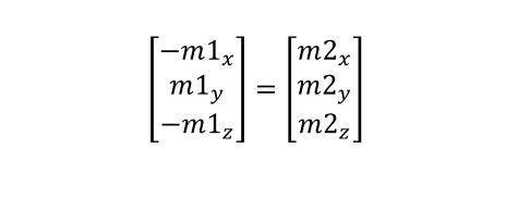
The relationship between m1 and m2 is expressed as follows.
ある理論上の理想システムにおいて、磁力計等の磁場測定手段は、磁場生成手段に対し軸方向にアラインされかつ可能な限り近接して位置合わせされることになる。薬物送達デバイス本体に当てはめた場合、これは、磁力計がデバイス本体の長手方向軸に沿って配置されなければならなくなることを含意する。このような理論上の理想システムでは、磁場外乱もないものと思われる。システム内の磁石により生成される磁場は、全て、薬物送達デバイス本体の長手方向軸に垂直な平面と同一平面上にあることになる。システム内の磁石により生成される磁場は、全て、磁石と磁力計との距離に直にリンクされる法線を有することになる。言い替えれば、生成されかつ測定される磁場は、磁石の回転角に関わりなく、かつ前記回転角とは独立して、薬物送達デバイス本体の長手方向軸に沿った磁石の平行移動と直に相関可能である。このような理想システムでは、測定される磁場の3つの極座標のうちの2つを用いることにより、微小の磁場外乱を除いて、磁石の回転角が正しく計算される。 In a theoretical ideal system, a magnetic field measuring means, such as a magnetometer, would be axially aligned and positioned as closely as possible to the magnetic field generating means. Applied to the drug delivery device body, this would imply that the magnetometer would have to be positioned along the longitudinal axis of the device body. In such a theoretically ideal system, it seems that there is no magnetic field disturbance. The magnetic fields generated by the magnets in the system will all be coplanar with a plane perpendicular to the longitudinal axis of the drug delivery device body. All magnetic fields generated by magnets in the system will have a normal that is directly linked to the distance between the magnet and the magnetometer. In other words, the magnetic field generated and measured can be directly correlated with translation of the magnet along the longitudinal axis of the drug delivery device body, regardless of and independent of the angle of rotation of the magnet. is. In such an ideal system, using two of the three polar coordinates of the measured magnetic field, the rotation angle of the magnet is correctly calculated up to small field disturbances.
ここで、
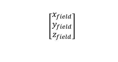
は、測定される任意の所与の磁場の座標であり、よって、回転角を次式のように計算することができる。
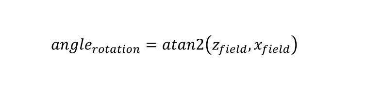
is the coordinate of any given magnetic field to be measured, so the angle of rotation can be calculated as
しかしながら、現実世界では、システムは、理想的に動作せず、上で同定した理想の仮想構成を達成することができない。本発明によるシステムにおいて、磁場測定手段は、薬物送達デバイス本体の長手方向軸と軸方向にアラインしているものの、略円板形磁石の回転軸と相互にアラインされず、とはいえ、薬物送達デバイス本体の長手方向軸に略平行である。このような構成は、幾つかの望ましくない効果をもたらし、とりわけ、
測定される各磁場の法線投影が、
(a)薬物送達デバイス本体の長手方向軸に沿った磁石の距離と、
(b)磁場測定手段の変位された非軸方向アラインメントに起因して、磁石の最大磁場ポテンシャルに対して距離の揺動、ひいては、法線投影の揺動を生み出す、磁石の回転角と、の関数として変化し、
法線投影の角度に対する測定された磁場の角度の差が、回転の距離および角度の双方の関数として変化する、言い替えれば、測定される磁場と法線投影とがもはや同一平面上にない。
However, in the real world, the system does not behave ideally and cannot achieve the ideal virtual configuration identified above. In the system according to the invention, the magnetic field measuring means are axially aligned with the longitudinal axis of the drug delivery device body, but not mutually aligned with the axis of rotation of the generally disk-shaped magnet, although the drug delivery is performed. substantially parallel to the longitudinal axis of the device body. Such a configuration has several undesirable effects, among others:
The normal projection of each magnetic field measured is
(a) the distance of the magnets along the longitudinal axis of the drug delivery device body;
(b) the angle of rotation of the magnet, which, due to the displaced non-axial alignment of the magnetic field measuring means, produces a fluctuation in the distance, and thus in the normal projection, relative to the maximum magnetic field potential of the magnet; change as a function,
The difference in the angle of the measured magnetic field relative to the angle of the normal projection varies as a function of both the distance and the angle of rotation, in other words the measured magnetic field and the normal projection are no longer coplanar.
さらに、実際のシステムには、以下を含む、説明される必要のある他の誤差も存在する。
各磁力計に起因するオフセットおよび較正誤差、
各磁力計に固有の感度誤差、および行われる各測定の誤差、
外的な磁場外乱に起因して生じる誤差、但しこれは、主に地球固有の磁場である、
システムを構成するコンポーネントの機械公差により誘発される誤差。
Additionally, there are other errors in real systems that need to be accounted for, including the following.
offset and calibration errors due to each magnetometer,
the sensitivity error inherent in each magnetometer and the error of each measurement made,
Errors caused by external magnetic field disturbances, which are mainly the earth's intrinsic magnetic field,
Errors induced by mechanical tolerances of the components that make up the system.
上記に鑑みれば、実際のシステム構成は、もはや、仮想上の理想システムに関して示される単純な方法で回転角を正しく計算することができない。XZ平面に沿った投影に関して行われる近似は、いずれも、主に角度差の変化および磁石の回転角で変わる法線投影に起因して、大きな誤差を導く傾向がある。さらに、磁場の法線も、磁石の回転との組合せで磁石により動かされる平行移動距離によって変わることから、投与量選択ホイールの真の角回転位置の有効解釈は、いずれも極めて問題含みとなる。 In view of the above, a real system configuration can no longer correctly calculate the rotation angle in the simple way shown for the hypothetical ideal system. Any approximations made with respect to projections along the XZ plane tend to lead to large errors, mainly due to changes in angular difference and normal projections that vary with the rotation angle of the magnets. Furthermore, any valid interpretation of the true angular rotational position of the dose selection wheel is highly problematic, since the magnetic field normal also varies with the translational distance moved by the magnet in combination with the rotation of the magnet.
本発明によるシステムは、これらの困難を解決し、かつさらに、磁場測定手段と略円板形の直径方向双極子磁石との非軸方向アラインメントに影響されない正確な回転角、ひいては、投与量ホイール設定を計算するための手段を提供する。さらに、本発明によるシステムは、そうした計算が望ましい場合には、補正されかつ正確に計算された回転角を用いることによって、任意選択によりかつ効果的には、薬物送達デバイス本体の長手方向軸に沿った磁石の平行移動距離の正確な計算も可能にする。 The system according to the present invention overcomes these difficulties and additionally provides precise rotation angle and thus dose wheel setting independent of non-axial alignment of the magnetic field measuring means and the generally disk-shaped diametric dipole magnet. provides a means for computing Moreover, the system according to the present invention optionally and effectively along the longitudinal axis of the drug delivery device body by using a corrected and accurately calculated rotation angle when such calculation is desired. It also allows accurate calculation of the translational distance of the magnet.
デバイスを構成するコンポーネントの機械的相互作用に起因する誤差、および磁場測定手段の相対感度に起因する誤差は、正しい回転角の計算における誤差の考えられるソースとして言及されているが、これらのソースは、本発明によるシステムでは取るに足らないものとされ、よって無視されている。 Errors due to the mechanical interaction of the components that make up the device, and errors due to the relative sensitivities of the magnetic field measuring means, are mentioned as possible sources of error in the calculation of the correct angle of rotation, although these sources are , is trivialized and thus ignored in the system according to the invention.
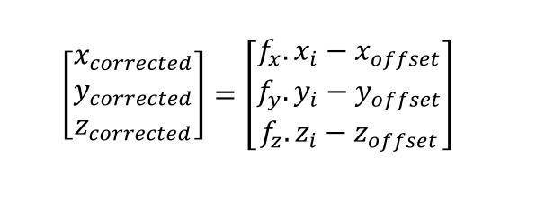
したがって、本発明による投与量制御システムの別の実施形態において、一体式制御ユニットは、さらに、前記磁場測定手段のオフセット値を、次式によって計算するように構成され、

ここで、x、yおよびzは、磁場の直交する3軸であり、かつ、
xi、yiおよびziは、3次元の点のクラウドに似た測定磁場の対応するベクトルによって生成される一連の点であり、前記点のクラウドは、次の因数、
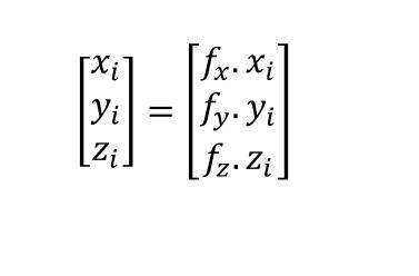
によってスフェリサイズ(sphericize)される。
Therefore, in another embodiment of the dose control system according to the invention, the integrated control unit is further arranged to calculate the offset value of said magnetic field measuring means according to the formula:
where x, y and z are the three orthogonal axes of the magnetic field, and
x i , y i and z i are the series of points generated by the corresponding vectors of the measured magnetic field that resemble a three-dimensional point cloud, said point cloud being a factor of:
It is spherized by
別の実施形態によれば、磁気オフセット値は、次式によって補正される。
磁力計が、任意選択により、かつ効果的には、予め較正されていれば、スフェリサイズ因数(sphericizing factors)fx、fyおよびfzは、1に等しく、よって、上述のオフセット値補正式ではもはや不要である。 If the magnetometer is optionally and advantageously pre-calibrated, the sphericizing factors f x , f y and f z are equal to 1, thus the above offset value correction no longer needed in the formula.
さらに別の実施形態において、第1および第2の磁力計は、さらに、投与量制御システムに悪影響を及ぼし得る外部磁場を全て打ち消すように構成される。悪影響を及ぼす外部磁気が発生すると、本文書の説明ではm1およびm2として識別可能な第1および第2の磁力計は、共に、同じ外部磁場に曝される。この状況は、次のように表すことができる。
CMm1:磁力計m1により測定される磁場
CMm2:磁力計m2により測定される磁場
CAm1:磁力計m1により測定される、磁石により生成される実際の磁場
CAm2:磁力計m2により測定される、磁石により生成される実際の磁場
CE:外部磁場、
およびこれらのコンポーネント間の関係は、次のように定義される。
CMm1=CAm1+CE
CMm2=CAm2+CE
In yet another embodiment, the first and second magnetometers are further configured to cancel any external magnetic fields that may adversely affect the dose control system. When a detrimental external magnetic field occurs, both the first and second magnetometers, identifiable as m1 and m2 in the description of this document, are exposed to the same external magnetic field. This situation can be expressed as follows.
CMm1: the magnetic field measured by magnetometer m1 CMm2: the magnetic field measured by magnetometer m2 CAm1: the actual magnetic field generated by the magnet, measured by magnetometer m1 CAm2: the magnetic field measured by magnetometer m2 Actual magnetic field generated CE: external magnetic field,
and the relationships between these components are defined as follows:
CM m1 = CA m1 + CE
CMm2 = CAm2 + CE
外部磁場は、CRを、次式のように定義される擬似合成磁場とすることによって打ち消すことができる。
CR=CMm1-CMm2=(CAm1+CE)-(CAm2+CE)=CAm1-CAm2
The external magnetic field can be canceled by letting CR be the quasi-synthetic magnetic field defined as:
CR = CM m1 - CM m2 = (CA m1 + CE) - (CA m2 + CE) = CA m1 - CA m2
CAm1およびCAm2は、一方が他方に対して同様に、準平行式に、かつ機能的に磁力計m1と磁力計m2との距離に依存して展開する。結果として、CRは、測定磁場CAm1およびCAm2から計算される合成擬似磁場を表す擬似ベクトルとして記述されることが可能であり、かつCRの値は、CAm1およびCAm2の値の間に含まれ、これにより、前記擬似ベクトルは、前記測定磁場に類似する方法で、すなわちCAm1およびCAm2に準平行に展開する。したがって、CRは、システム外部の磁場外乱とは独立して、磁石の回転角を表し、かつこれにより、投与量セレクタホイールを表す。CAm1およびCAm2は、リンクされて展開する法線を表示することから、CAm1の法線が大きくなれば、CAm2の法線も大きくなり、逆も真である。したがって、次の関係式も常に真である。
│CAm1│>│CAm2│
CA m1 and CA m2 evolve one with respect to the other in a quasi-parallel manner and functionally depending on the distance between magnetometers m1 and m2 . As a result, CR can be described as a quasi-vector representing the resultant quasi-field calculated from the measured magnetic fields CA m1 and CA m2 , and the value of CR is between the values of CA m1 and CA m2 included, whereby the pseudovectors evolve in a manner analogous to the measured magnetic fields, ie quasi-parallel to CA m1 and CA m2 . CR therefore represents the angle of rotation of the magnet and thereby the dose selector wheel, independent of magnetic field disturbances outside the system. Since CA m1 and CA m2 display normals that are linked and unfolding, the greater the normal of CA m1 , the greater the normal of CA m2 and vice versa. Therefore, the following relation is also always true.
│CAm1│>│CAm2│
したがって、本発明のさらに別の実施形態において、一体式処理ユニットは、磁場測定手段により測定される磁場値を、磁場測定手段の略円板形の直径方向単一双極子磁石に対する非軸方向アラインメントの関数として補正するように構成される。 Thus, in yet another embodiment of the present invention, the integrated processing unit aligns the magnetic field values measured by the magnetic field measuring means with the non-axial alignment of the magnetic field measuring means with respect to the substantially disc-shaped diametrical single dipole magnet. is configured to correct as a function of
さらなる実施形態において、一体式処理ユニットは、磁場測定手段により測定される、かつ磁場測定手段と略円板形の直径方向単一双極子磁石との軸方向アラインメントの欠如から結果的に生じる磁場値を、前記第1および第2の磁場測定手段の測定磁場から計算される合成擬似磁場を表す擬似ベクトルへ直交する3軸x、yまたはzのうちの1つを中心とする回転を印加して前記合成擬似磁場を表す前記擬似ベクトルを等法線投影にすることにより、補正するように構成される。 In a further embodiment, the integrated processing unit has a magnetic field value measured by the magnetic field measuring means and resulting from the lack of axial alignment between the magnetic field measuring means and the generally disc-shaped diametric single dipole magnet. by applying a rotation about one of the three axes x, y or z orthogonal to the pseudo-vector representing the resultant pseudo-magnetic field calculated from the measured magnetic fields of said first and second magnetic field measuring means It is arranged to correct by isonormal projection of the pseudo-vector representing the resultant pseudo-magnetic field.
さらに別の実施形態において、一体式処理ユニットは、磁場測定手段により測定される、かつ磁場測定手段と略円板形の直径方向単一双極子磁石との軸方向アラインメントの欠如から結果的に生じる磁場値を、以下の計算を適用することによって補正するように構成され、以下の計算において、直交する3軸X、YおよびZを有するシステムのdは、Y軸に沿った、薬物送達デバイス本体の近位端と略円板形磁石との距離に等しい。各距離dについて、X軸を通る平面が存在し、よって、前記平面と同一平面上にある磁場の平面XZに沿った投影は、磁石の回転角に関わりなく、かつ前記回転角とは独立して、全て等法線である。この平面は、等法線投影として知られる。この計算は、次のように表すことができる。
Rxは、単位度で示される角度であって、磁場擬似ベクトルの、好ましくはX軸である直交する1つの軸を中心とする回転による変換を有効化して前記磁場擬似ベクトルを位置合わせし、よって、前記擬似ベクトルは、その等法線投影と略同一平面となる。
In yet another embodiment, the integrated processing unit is measured by the magnetic field measuring means and results from the lack of axial alignment between the magnetic field measuring means and the generally disc-shaped diametric single dipole magnet. The magnetic field values are configured to be corrected by applying the following calculation, where d for a system with three orthogonal axes X, Y and Z is along the Y axis, the drug delivery device body is equal to the distance between the proximal end of the magnet and the approximately disk-shaped magnet. For each distance d, there is a plane through the X axis, so that the projection along the plane XZ of the magnetic field coplanar with said plane is independent of and independent of the angle of rotation of the magnet. are all isonormals. This plane is known as the isonormal projection. This calculation can be expressed as:
R x is an angle in degrees that enables transformation of the magnetic field pseudovector by rotation about one orthogonal axis, preferably the X axis, to align said magnetic field pseudovector; Thus, the pseudo-vector is substantially coplanar with its isonormal projection.
θxは、X軸を中心として測定される実際の回転角(単位度)であり、よって、

であり、かつ、
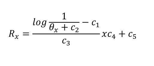
である。
θ x is the actual rotation angle (in degrees) measured about the X axis, thus
and
is.
上式において、c1~c5は、各システム毎に計算される定数であり、かつとりわけ、
前記第1の磁力計(m1)と前記第2の磁力計(m2)との相対的空間位置、
前記第1および第2の磁力計の物理的特性、
略円板形の直径方向単一双極子磁石の磁場生成能力、
略円板形の直径方向単一双極子磁石のサイズ、
距離d、および、
その他、適切と思われる任意選択のパラメータ、
を考慮した定数である。
where c 1 to c 5 are constants calculated for each system and, inter alia,
relative spatial positions of said first magnetometer (m 1 ) and said second magnetometer (m 2 );
physical characteristics of the first and second magnetometers;
magnetic field generation capability of a nearly disc-shaped diametric single dipole magnet,
the size of a roughly disc-shaped diametric single dipole magnet,
distance d, and
any other optional parameters as you see fit;
is a constant that takes into account
因数または定数c1~c5は、次のように決定することができる。
磁場の値の代表的な部分集合について、データセットを生成する。データは、様々な代表的距離dについて生成される。このようなデータ生成シミュレーションでの使用に適するシミュレーションソフトウェアプログラムまたはライブラリは、Infineonが提供する「3D磁気センサ設計ツール」として知られるものであり、ウェブページ、URL:http://design.infineon.com/3dsim/#/からアクセス可能である。
The factors or constants c 1 -c 5 can be determined as follows.
A data set is generated for a representative subset of magnetic field values. Data are generated for various representative distances d. A simulation software program or library suitable for use in such data generation simulations is known as the "3D Magnetic Sensor Design Tool" provided by Infineon and can be found on the web page, URL: http://design. infineon. com/3dsim/#/.
Rxを、シミュレーション毎にθxの関数として近似し、これにより、投影される各磁場ベクトルの法線間の差を等法線投影に対して最小化する。 We approximate R x as a function of θ x for each simulation, thereby minimizing the difference between the normals of each projected magnetic field vector to the isonormal projections.
Rxを、各距離dのθx値についてモデリングし、di、θxiおよびRxiの値セットを得る。以下に示す値は、ある特定のシステムに関する、単に例示を目的とするものである。
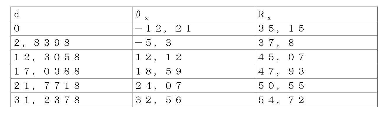
ここで、Rxは、次のようにモデリングすることができる。

ここで、
である。
R x is modeled for each distance d θ x value to obtain a set of values for d i , θ xi and R xi . The values shown below are for illustrative purposes only, for a particular system.
where R x can be modeled as:
here,
is.
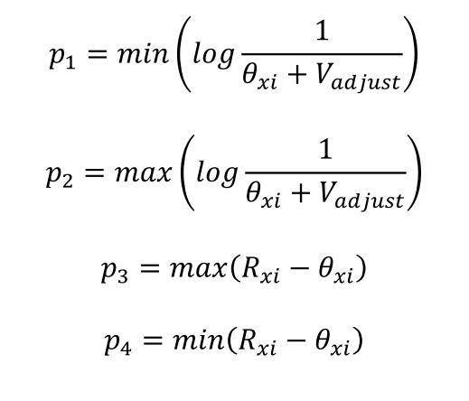
Vadjustは、シミュレーションによって得られる近似されたRx値と、システムによって計算されるRx値との誤差を最小化するための調整変数である。 V adjust is an adjustment variable to minimize the error between the approximated R x value obtained by simulation and the R x value calculated by the system.
上記から、因数c1~c5について次のような属性を作成することができる。
c1=p1
c2=Vadjust
c3=p2-p1
c4=p4-p3
c5=p3
From the above, the following attributes can be created for the factors c 1 -c 5 .
c 1 = p 1
c2 = V adjust
c 3 = p 2 - p 1
c 4 = p 4 - p 3
c5 = p3
本発明によるシステムで使用するc1~c5の値の適切な例は、次の通りであり得る。
c1=-2.31864756900365
c2=175.72
c3=0.105103250465988
c4=25.2
c5=22.16
Suitable examples of values for c 1 -c 5 for use in the system according to the invention may be as follows.
c 1 =-2.31864756900365
c2 = 175.72
c3 = 0.105103250465988
c4 = 25.2
c5 = 22.16
別の実施形態において、一体式処理ユニットは、読み取り誤差の計算への拡大を回避する手助けをするために、処理中に得られるRx値を制限すべく低いカットオフ値、および高いカットオフ値を適用するように構成される。これは、例えば、機能システムの動作限界において、低いカットオフ、および高いカットオフとして各々min(θx)およびmax(θx)等の関数を用いることにより実現することができる。 In another embodiment, the integrated processing unit uses a low cutoff value and a high cutoff value to limit the Rx values obtained during processing to help avoid magnifying reading errors into the calculation. is configured to apply This can be achieved, for example, by using functions such as min(θ x ) and max(θ x ) as the low cutoff and high cutoff, respectively, in the operational limits of the functional system.
本発明のさらなる実施形態において、投与量制御システムは、さらに、一体式制御ユニットからの情報のリモートおよび/またはローカルデータ処理システムへの通信を可能にするように構成される通信手段を備える。 In a further embodiment of the invention, the dose control system further comprises communication means configured to enable communication of information from the integrated control unit to remote and/or local data processing systems.
本発明のさらに別の実施形態において、リモートおよび/またはローカルデータ処理システムは、スマートフォンアプリケーションを含む。 In yet another embodiment of the invention, the remote and/or local data processing system includes a smart phone application.
本発明のさらに別の実施形態において、投与量制御システムは、さらに、リモートおよび/またはローカルデータ処理システムへ通信される一意の識別子を含む。 In yet another embodiment of the invention, the dose control system further includes a unique identifier that is communicated to the remote and/or local data processing system.
本発明の別の実施形態において、投与量制御システムは、さらに、温度検出手段を備える。 In another embodiment of the invention, the dose control system further comprises temperature sensing means.
本発明の別の実施形態において、投与量制御システムは、さらに、時間決定手段を備える。 In another embodiment of the invention the dose control system further comprises a timing means.
本発明のさらなる実施形態において、投与量制御システムは、さらに、自律電源手段を備える。 In a further embodiment of the invention the dose control system further comprises an autonomous power supply means.
本発明のさらに別の実施形態において、前記投与量制御システムは、市販の注射可能な薬物送達デバイスと比較して、前記薬物送達システムの妨げられない、または変わらぬ操作方法を許容するように構成される。 In yet another embodiment of the present invention, the dose control system is configured to allow an unimpeded or unchanged method of operation of the drug delivery system compared to commercially available injectable drug delivery devices. be done.
本発明のさらに別の実施形態では、本明細書において略説明されかつ例示されている投与量制御システムにおいて投与量設定を計算するための方法が提供され、前記方法は、
-回転可能な略円板形の直径方向単一双極子磁石により生成される磁場(CM)を、前記磁石の回転軸に対して変位される軸方向アラインメントで配置される少なくとも第1の磁力計(m1)および第2の磁力計(m2)によって測定するステップと、
-結果的に生じる磁場擬似ベクトル(CR)を計算するステップと、
-任意選択により、前記測定された磁場CMm1およびCMm2を補正するステップと、
-前記磁場擬似ベクトルについて、投影の等法線平面に対する回転角を計算するステップと、
-前記回転角を有する前記磁場擬似ベクトルを変換して、回転および投影により、等法線が補正された磁場擬似ベクトル(CR2)を生成するステップと、
-前記補正された等法線磁場擬似ベクトルから、前記回転軸を中心とする前記磁石の回転角を計算するステップとを含む。
In yet another embodiment of the present invention, a method is provided for calculating dose settings in a dose control system generally described and exemplified herein, said method comprising:
- at least a first magnetometer arranged in an axial alignment displaced with respect to the axis of rotation of said magnet for the magnetic field (CM) produced by a rotatable generally disk-shaped diametric single dipole magnet; (m 1 ) and measuring with a second magnetometer (m 2 );
- calculating the resulting magnetic field pseudovector (CR);
- optionally correcting said measured magnetic fields CMm1 and CMm2;
- calculating, for said magnetic field pseudo-vector, the angle of rotation with respect to the iso-normal plane of the projection;
- transforming said magnetic field pseudo-vector with said rotation angle to produce an isonormal corrected magnetic field pseudo-vector (CR2) by rotation and projection;
- calculating the angle of rotation of the magnet about the axis of rotation from the corrected isonormal magnetic field pseudo-vectors;
上記方法のさらに別の実施形態において、前記方法は、さらに、前記回転軸に沿った前記磁石の平行移動された位置に対応する前記磁石の法線上の基準位置を計算することを含む。 In yet another embodiment of the above method, the method further comprises calculating a normal reference position of the magnet corresponding to the translated position of the magnet along the axis of rotation.
本発明の様々な実施形態において述べているように、投与量制御システムは、薬物送達デバイスの投与量ホイールセレクタへ取り外し可能に取り付け可能な、またはこれへ永久的に固定される略円板形の直径方向単一双極子磁石を備える。このような磁石により生成される磁場は、前記磁石の周りに既知の方法で空間的に広がり、かつこの磁場は、適切に設けられる磁場測定手段によって測定されることが可能である。本発明のさらなる説明に関連して理解されるであろうが、この磁場は、角回転位置、および任意選択によりさらに、効果的には、本事例では薬物送達デバイス本体の長手方向軸に沿っている法線に沿った位置、を計算するために使用される。この角回転位置または任意選択によりかつ効果的には法線が、本発明のシステムにより提供されるような精度で知られると、前記システムは、略円板形の直径方向単一双極子磁石が回転動作可能式に前記投与量セレクタホイールの近位端に位置合わせされる、または前記投与量セレクタホイールへ取り付けられるという事実に起因して、投与量セレクタホイールの対応する投与量設定を計算し、かつ効果的には、前記値をユーザ、医療専門家、またはローカルまたはリモートコンピュータ、サーバ、分散型データ記憶設備等のローカルまたはリモートデータ処理システム、または他の形式のデジタルデータ記憶装置および通信設備へ通信することができる。 As described in various embodiments of the present invention, the dose control system includes a generally disc-shaped body that is removably attachable to or permanently affixed to a dose wheel selector of a drug delivery device. Equipped with a diametrical single dipole magnet. The magnetic field generated by such a magnet extends spatially around said magnet in a known manner, and this magnetic field can be measured by appropriately provided magnetic field measuring means. As will be understood in connection with the further description of the invention, this magnetic field is aligned along the angular rotational position, and optionally also, effectively in the present case, along the longitudinal axis of the drug delivery device body. is used to calculate the position along the normal that Once this angular rotational position, or optionally and effectively the normal, is known with such accuracy as provided by the system of the present invention, said system is capable of detecting a generally disk-shaped diametric single dipole magnet. calculating the corresponding dose setting of the dose selector wheel due to the fact that it is rotationally operably aligned with or attached to the proximal end of said dose selector wheel; and advantageously to a user, medical professional, or local or remote data processing system, such as a local or remote computer, server, distributed data storage facility, or other form of digital data storage and communication facility. can communicate.
磁場を生成するための手段は、例えば、古典的な磁石、電磁石、混合材料磁石といった様々なものが知られている。このような磁石は、典型的には、生来的であるか、または電気的または他のエネルギーフローが前記材料を横断しまたはこれに影響を与えて前記材料内に磁場を生成または誘導するかに関わらず、磁気特性または常磁性特性を有する磁化可能材料から作られる。適切な材料は、以下から適切に選択されることが可能である。
-例えば鉄、酸素およびストロンチウムの結晶化合物を含む、フェライト磁石、特に、焼結フェライト磁石、
-熱可塑性マトリクスおよび等方性ネオジム-鉄-ホウ素粉末からなる複合材料、
-熱可塑性マトリクスおよびストロンチウム系ハードフェライト粉末で構成される複合材料。これにより、結果的に生じる磁石は、等方性、すなわち非配向性の、または異方性、すなわち配向性のフェライト粒子を包含することができる、
-熱硬化性マトリクスおよび等方性ネオジム-鉄-ホウ素粉末で製造される複合材料、
-例えば、合成ゴムまたはPVCと混合された重荷電ストロンチウムフェライト粉末で製造され、その後、所望される形状に押し出されるか、カレンダ掛けして微細シートにされる磁性エラストマー、
-概して茶色いシートの外観を有し、かつその厚さおよびその組成に依存して多かれ少なかれ柔軟であるカレンダ掛けされた軟質複合材。これらの複合材は、決してゴムのような弾性ではなく、60~65Shore D ANSI範囲のショア硬度を有する傾向がある。このような複合材は、概して、ストロンチウムフェライト粒子が充填された合成エラストマーから形成される。結果的に生じる磁石は、異方性または等方性である可能性があり、シートの多様性は、概してカレンダ掛けに起因する磁性粒子のアラインメントを有する、
-概して上述のような軟質複合材を含む、軟鉄極板で相互に積層されるラミネート複合材、
-ネオジム-鉄-ホウ素磁石、
-アルミニウム-ニッケル-コバルト合金で製造され、かつ磁化された鋼、
-サマリウム・コバルト合金。
Various means for generating magnetic fields are known, for example classical magnets, electromagnets, mixed material magnets. Such magnets are typically either intrinsic, or electrical or other energy flows traverse or affect the material to create or induce a magnetic field within the material. Regardless, it is made from a magnetizable material with magnetic or paramagnetic properties. Suitable materials can be suitably selected from:
- ferrite magnets, in particular sintered ferrite magnets, containing for example crystalline compounds of iron, oxygen and strontium,
- a composite material consisting of a thermoplastic matrix and isotropic neodymium-iron-boron powder,
- A composite material consisting of a thermoplastic matrix and a strontium-based hard ferrite powder. Thereby, the resulting magnet can include isotropic, i.e. non-oriented, or anisotropic, i.e. oriented, ferrite particles.
- composite materials made with a thermoset matrix and isotropic neodymium-iron-boron powder,
- magnetic elastomers, for example made of heavily charged strontium ferrite powder mixed with synthetic rubber or PVC, which are then extruded into the desired shape or calendered into fine sheets;
- A calendered flexible composite that generally has the appearance of a brown sheet and is more or less flexible depending on its thickness and its composition. These composites tend to have a Shore hardness in the 60-65 Shore D ANSI range, never as elastic as rubber. Such composites are generally formed from synthetic elastomers filled with strontium ferrite particles. The resulting magnets can be anisotropic or isotropic, the diversity of the sheets having the alignment of the magnetic particles generally due to calendering,
- laminate composites laminated to each other with soft iron plates, including soft composites generally as described above,
- neodymium-iron-boron magnets,
- steel made of aluminum-nickel-cobalt alloy and magnetized,
- samarium-cobalt alloys.
本発明において実装される略円板形の直径方向単一双極子磁石での使用に適する磁場生成手段の上記リストのうちでは、ネオジム-鉄-ホウ素永久磁石が好ましい。このような磁石は、比較的高い磁場の強さを保全しながら、比較的小さいサイズで寸法決めされるその能力が知られている。本発明において実装される略円板形の直径方向単一双極子磁石の絶対磁場強さは、本発明によるシステムの機能の補正にとって必須ではないが、磁石の磁場強さおよび磁場測定手段の位置合わせの双方は、第1の磁場測定手段で測定される値と第2の磁場測定手段で測定される値との間に少なくとも100マイクロテスラ(μT)の差が存在するように構成されることが好ましい。 Of the above list of magnetic field generating means suitable for use in the generally disk-shaped diametric single dipole magnets implemented in the present invention, neodymium-iron-boron permanent magnets are preferred. Such magnets are known for their ability to be sized at relatively small sizes while maintaining relatively high field strengths. The absolute magnetic field strength of the substantially disc-shaped diametric single dipole magnet implemented in the present invention is not essential for correcting the functioning of the system according to the present invention, but the magnetic field strength of the magnet and the position of the magnetic field measuring means both of the alignments are configured such that there is a difference of at least 100 microTesla (μT) between the value measured by the first magnetic field measuring means and the value measured by the second magnetic field measuring means; is preferred.
「略円板形」という言い回しは、磁石が、円形、楕円形または任意の適切な多角形でもあり得る、単に単一双極子、言い替えれば、直径方向に対向する1対のN磁極およびS磁極を有する一般的な円板形状を定義すると理解されるべきである。先に指摘したように、本発明において使用される磁石は、略円板形であるが、このような略円板形には、円板の略中心にオリフィスを有していてリングまたは環状形の磁石を形成する磁石も含まれ得る。 The phrase "substantially disk-shaped" means that the magnet may be circular, elliptical, or any suitable polygonal shape, simply a single dipole, in other words, a pair of diametrically opposed magnetic north and south poles. It should be understood to define a general disk shape with As pointed out above, the magnets used in the present invention are generally disc-shaped, but such generally disc-shaped magnets have an orifice approximately in the center of the disc and have a ring or annular shape. magnets forming a magnet of .
本発明の磁石は、薬物送達システムの長手方向軸を中心とする軸方向回転を実行し、かつ任意選択により前記長手方向軸に沿って平行移動するように構成される。回転変位は、投与量セレクタホイールの回転変位と一致し、つまりは、磁石が長手方向軸を中心にして回転すると、前記投与量セレクタホイールが同じ方向に回転する。概して、投与量セレクタホイールは、薬物送達デバイス本体の内部穴を横断する駆動シャフトまたは親ねじへ取り付けられる。このような投与量セレクタホイールを装備する薬物送達デバイスに概して当てはまるように、この磁石は、投与量セレクタホイールと共に長手方向へ、すなわち、注射されるべき投与量を増やす場合に、薬物送達デバイスの本体の近位端から近位方向へ、および投与量が減らされる場合に、デバイスの長手方向軸に沿って遠位方向にデバイスの近位端へ向かって戻る長手方向の反対方向へ、の双方で離れるように平行移動することができる。任意選択の、かつ効果的な実施形態では、このような構成において、システムは、長手方向軸に沿った移動距離を計算することもできる。別の実施形態において、投与量セレクタホイールは、長手方向の平行移動を実行するように構成されず、つまり、投与量セレクタホイールは、単に長手方向軸を中心にして回転するように構成され、かつこの回転移動は、時計回りまたは反時計回りに関わらず、選択される投与量を定義する。本発明による投与量制御システムは、元来、これらの構成のいずれにおいても適切に機能するように構成される。 The magnets of the present invention are configured to effect axial rotation about the longitudinal axis of the drug delivery system and optionally translation along said longitudinal axis. The rotational displacement coincides with the rotational displacement of the dose selector wheel, ie rotation of the magnet about its longitudinal axis rotates said dose selector wheel in the same direction. Generally, the dose selector wheel is attached to a drive shaft or lead screw that traverses the internal bore of the drug delivery device body. As is generally the case with drug delivery devices equipped with such a dose selector wheel, this magnet moves longitudinally with the dose selector wheel, i.e. when increasing the dose to be injected, to the body of the drug delivery device. and in the opposite longitudinal direction distally along the longitudinal axis of the device and back towards the proximal end of the device when the dose is reduced. Can be translated apart. In an optional and effective embodiment, in such a configuration the system can also calculate the distance traveled along the longitudinal axis. In another embodiment, the dose selector wheel is not configured to perform longitudinal translation, i.e., the dose selector wheel is configured solely to rotate about the longitudinal axis, and This rotational movement, whether clockwise or counterclockwise, defines the dose selected. A dose control system according to the present invention is inherently configured to function properly in any of these configurations.
さらに、磁場生成手段は、本発明によるこのような投与量制御システムのない薬物送達デバイスに比較して、磁場測定手段によって検出されるべき十分な磁場を提供するように寸法決めされ、よって、正常な動作におけるユーザの薬物送達デバイスの使用を妨げる。 Furthermore, the magnetic field generating means are dimensioned to provide a sufficient magnetic field to be detected by the magnetic field measuring means, compared to a drug delivery device without such a dose control system according to the invention, so that a normal prevent the user from using the drug delivery device in any motion.
本発明による投与量制御システムには、少なくとも第1および第2の磁場測定手段が存在し、略円板形磁石により生成される磁場を測定するように構成される。少なくとも第1および第2の磁場測定手段は、注射可能な薬物送達デバイスを介して投与するためにどの投与量が選択されているかを正確に決定すべく、略円板形磁石の回転運動および任意選択により平行移動運動により生成される磁場を測定し、磁場生成手段の角回転位置を正確に計算するために使用される。任意選択により、かつ効果的には、このようなシステムは、薬物送達デバイス本体の長手方向軸に沿った特定の基準点の平行移動位置を計算するために使用されることも可能であり、前記基準点は、投与される用量、システムのゼロ点、プライミング点または初期設定点、注射開始点および/または注射点と相関するために使用されることが可能である。 At least first and second magnetic field measuring means are present in the dose control system according to the invention and are arranged to measure the magnetic field produced by the generally disk-shaped magnet. At least the first and second magnetic field measuring means are adapted for rotational movement of the substantially disk-shaped magnet and optional Optionally, the magnetic field produced by translational motion is measured and used to accurately calculate the angular rotational position of the magnetic field generating means. Optionally and advantageously, such a system can also be used to calculate the translational position of certain reference points along the longitudinal axis of the drug delivery device body, said Reference points can be used to correlate doses administered, system zero points, priming or initialization points, injection start points and/or injection points.
回転角位置を決定するために磁場を測定する手段は、当技術分野で周知である。例えば、磁気抵抗器は、周知の手段であり、そのうちの一部は、先行技術システムに使用されている。このような磁気抵抗器は、これらのセンサコンポーネントが機能する物理的機構を指す略語を使って、例えばAMR、GMR、TMRセンサと呼ばれることが多い。巨大磁気抵抗(GMR)は、交互する強磁性および非磁性導電層で構成される薄膜構造体において観察される量子力学的磁気抵抗効果である。異方性磁気抵抗、すなわちAMRは、電気抵抗の、電流の方向と磁化の方向との間の角度に対する依存性が観察される材料に存在すると言われている。トンネル磁気抵抗(TMR)は、薄い絶縁体で分離される2つの強磁性体からなるコンポーネントである磁気トンネル接合(MTJ)において生じる磁気抵抗効果である。これらの様々な特性を用いる抵抗器は、それ自体が既知である。 Means for measuring magnetic fields to determine rotational angular position are well known in the art. For example, magnetoresistors are well known means, some of which are used in prior art systems. Such magnetoresistors are often referred to as AMR, GMR, TMR sensors, for example, using abbreviations that refer to the physical mechanisms by which these sensor components function. Giant magnetoresistance (GMR) is a quantum mechanical magnetoresistance effect observed in thin film structures composed of alternating ferromagnetic and nonmagnetic conductive layers. Anisotropic magnetoresistance, or AMR, is said to exist in materials in which a dependence of electrical resistance on the angle between the direction of current and the direction of magnetization is observed. Tunnel magnetoresistance (TMR) is a magnetoresistive effect that occurs in a magnetic tunnel junction (MTJ), a component consisting of two ferromagnetic materials separated by a thin insulator. Resistors using these various properties are known per se.
上記に鑑みて、本発明の投与量制御システムは、好ましくは、磁力計を用い、かつ好ましくは、少なくとも第1および第2の磁力計を用いる。これらの磁力計は、磁場の強さを直に測定するという点で、GMR、AMRまたはTMRセンサとは異なる。磁力計は、磁場を主に2つの方法で測定し、すなわち、ベクトル磁力計は、磁場のベクトル成分を測定し、全磁場磁力計またはスカラ磁力計は、ベクトル磁場の大きさを測定する。別のタイプの磁力計は、絶対磁力計であり、これは、磁気センサの内部較正または既知の物理定数を用いて絶対量またはベクトル磁場を測定する。相対磁力計は、固定的な、但し較正されていないベースラインに対する大きさまたはベクトル磁場を測定し、かつバリオメータとも呼ばれて磁場の変動を測定するために使用される。 In view of the above, the dose control system of the present invention preferably employs magnetometers, and preferably employs at least first and second magnetometers. These magnetometers differ from GMR, AMR or TMR sensors in that they directly measure the strength of the magnetic field. Magnetometers measure magnetic fields in two main ways: vector magnetometers measure the vector component of the magnetic field and total field or scalar magnetometers measure the magnitude of the vector magnetic field. Another type of magnetometer is the absolute magnetometer, which measures the absolute or vector magnetic field using the internal calibration of the magnetic sensor or known physical constants. A relative magnetometer measures a magnitude or vector magnetic field relative to a fixed but uncalibrated baseline and is also called a variometer and is used to measure variations in the magnetic field.
本発明による投与量制御システムにおける使用に適する、かつ好ましい磁力計は、超低電力高性能の3軸ホール効果磁力計である。磁力計は、互いに垂直または直交する3軸に渡る磁場を測定するように構成されることが可能であるとはいえ、磁場測定手段は、直交する3軸のうちの2つのみ、例えばX軸およびZ軸のみに渡って磁場を測定するように構成されることも好ましく、これにより、Y軸は、本発明の例示的なシステムにおいて、薬物送達デバイス本体の長手方向軸と同軸であり、よって、前記軸上の基準点位置に関して先に示したように、投与量セレクタホイールの前記長手方向軸に沿った平行移動動作に関連する距離の測定値をそれに沿って計算することができる法線に一致する。 A suitable and preferred magnetometer for use in a dose control system according to the present invention is an ultra-low power, high performance, 3-axis Hall effect magnetometer. Although the magnetometer can be configured to measure the magnetic field over three mutually perpendicular or orthogonal axes, the magnetic field measuring means only measure two of the three orthogonal axes, e.g. and the Z-axis only, whereby the Y-axis is coaxial with the longitudinal axis of the drug delivery device body in an exemplary system of the invention, thus , as indicated above with respect to the position of the reference point on said axis, to the normal along which distance measurements associated with translational movement of the dose selector wheel along said longitudinal axis can be calculated. match.
また、投与量制御システムは、効果的には、磁場測定手段へ連結される、磁場測定手段から受信される情報を処理するための一体式制御ユニットも備える。この一体式制御ユニットは、例えば、適切な寸法の、例えば長さ約45mm、幅15mm、深さ1.5mmのプリント基板上へ取り付けることができる。一体式制御ユニットは、投与量制御システムの異なる電子コンポーネント間の全ての電気通信およびシグナル伝達を処理する。また、一体式制御ユニットは、投与量管理システムの実行、および磁石の正確な位置ロケーションが計算されかつ決定されることを可能にする計算、ならびに、自律電力手段および通信手段からの信号の、例えばスマートフォン上のローカルまたはリモートデータ処理システムを使用する処理も担当する。一体式制御ユニットは、一体式制御ユニットを含む現在の他の電子デバイスと同様にして、初回使用時に遠隔的にプログラムされ得、または情報および更新を受信することができる。このような一体式制御ユニットは、それ自体が既知であって、多くの場合、中央処理装置、リアルタイムクロック、1つまたは複数のメモリストレージシステム、および任意選択により通信システムまたは通信サブシステムを、他の所望されるコンポーネントと共に統合する。 The dose control system also advantageously comprises an integrated control unit coupled to the magnetic field measuring means for processing information received from the magnetic field measuring means. This integrated control unit can, for example, be mounted on a printed circuit board of suitable dimensions, for example about 45 mm long, 15 mm wide and 1.5 mm deep. An integrated control unit handles all electrical communication and signaling between the different electronic components of the dose control system. The integrated control unit also controls the execution of the dose management system and the calculations that allow the precise positional location of the magnet to be calculated and determined, as well as signals from the autonomous power means and communication means, e.g. Also responsible for processing using local or remote data processing systems on smartphones. The integrated control unit, like other current electronic devices that include an integrated control unit, can be remotely programmed on first use or receive information and updates. Such integrated control units are known per se and often include a central processing unit, a real-time clock, one or more memory storage systems, and optionally a communication system or subsystem, among others. with the desired components of
本発明の投与量制御システムは、薬物送達デバイスの本体に取り外し可能に取り付けられるだけでなく、磁場の測定を介して角度位置または任意選択により、効果的には法線の計算を正確に提供することもでき、これにより、薬物送達デバイス自体の本体内に、かつ薬物送達デバイス本体の長手方向軸と同軸に、または前記長手方向軸に近接して全てのコンポーネントを配置する必要なしに、対応する選択された投与量を計算する投与量制御システムを提供することにより、過去のソリューションとの明確な決別を示す。実際に、本発明の投与量制御システムは、出願人が、現在市販されている様々な異なる薬物送達デバイス、具体的には、患者による自己治療用に現時点で流通されているペン型インスリン自己注射器、但しこれに限定されない、によって使用され得る、取り外し可能に取り付けることができるシステムを提供することを可能にしている。 The dose control system of the present invention is not only removably attached to the body of the drug delivery device, but also provides accurate calculation of angular position or, optionally, normal, effectively through measurement of the magnetic field. It is also possible to accommodate all components within the body of the drug delivery device itself and coaxial with or in close proximity to the longitudinal axis of the drug delivery device body. It represents a clear departure from past solutions by providing a dose control system that calculates the selected dose. Indeed, the dose control system of the present invention has been found by Applicants to be useful in a variety of different drug delivery devices currently on the market, specifically insulin pen autoinjectors currently in circulation for self-medication by patients. It makes it possible to provide a removably attachable system that can be used by, but not limited to,
次に、図1を参照すると、本発明による投与量制御システム(1)のコンポーネントの略図が表示されている。このような投与量制御システムは、例えば、一体式制御ユニット(2)を備え、一体式制御ユニット(2)は、例えばプリント基板上に、または上に様々なコンポーネントが互いに連結されて搭載される等価物上に搭載される。一体式制御ユニット(2)は、それ自体が既知であるように、シリコンまたはこれに類似するものに刻まれる、またはエッチングされる回路で構成される可能性もある。実際には、所望されれば、当技術分野で周知であるように、投与量制御システム全体をシリコンまたは他の類似する半導体材料の単一ブロックまたは複数の相互接続されたブロックに彫り込むことも可能である。一体式制御ユニット(2)は、システムの様々なコンポーネント間の信号および通信の処理および管理を担当し、かつシステム内に記憶される、または前記システム上で遠隔的に動作可能なプログラムコードの計算および実行も担当する中央処理装置(CPU、3)を備える。一体式制御ユニット(2)は、さらに、投与量制御システム内で時間を刻みかつ測定するためのリアルタイムクロック(RTC、4)を備えることができる。リアルタイムクロック(RTC、4)は、システム内の様々なイベントの時間および時間差を計算するために、中央処理装置(CPU、3)がエネルギーを供給される間に、例えば、周波数測定を用いて中央処理装置(CPU、3)へ直に統合されることも可能である。投与量制御システムは、また、好ましくは、通信サブシステム(COM、5)、例えば低電力消費ブルートゥース無線デバイス、も装備し、この通信サブシステムは、投与量制御システムがローカルまたはリモートデータ処理システム(不図示)、例えば投与量制御システムの使用に関する情報およびフィードバックをユーザへ提供するために使用されるPC、サーバ、分散型データストレージまたは他のデジタルデータストレージ設備、もしくはスマートフォンおよび対応するスマートフォンアプリケーションとも通信できるようにする。さらに、システムは、好ましくは、一時的であれ永続的であれシステム内に情報を記憶するための何らかの形式のメモリストレージ(MEM、6)も有し、前記情報は、様々なソースから着信し、システムの他のエンドポイントから測定または決定される値または信号、中央処理装置(CPU、3)により計算または記憶される値、スマートフォン等のリモートまたはローカルデータ処理システムから受信される値またはデータ、システム較正のための工場設定値、デバイスを一意に識別する一意の識別子手段またはデータ、およびこれらに類似するものを含む。このようなメモリストレージシステム(MEM、6)は、当業者にそれ自体が既知である。 Referring now to Figure 1, a schematic representation of the components of a dose control system (1) according to the present invention is displayed. Such a dose control system comprises, for example, an integrated control unit (2), which is mounted, for example, on or on a printed circuit board with the various components coupled together. Mounted on an equivalent. The integrated control unit (2) may also consist of circuitry that is engraved or etched into silicon or the like, as is known per se. In fact, if desired, the entire dose control system may be engraved into a single block or multiple interconnected blocks of silicon or other similar semiconductor material, as is well known in the art. It is possible. The integrated control unit (2) is responsible for processing and managing signals and communications between the various components of the system and computing program code stored within the system or operable remotely on said system. and a central processing unit (CPU, 3) that is also responsible for execution. The integrated control unit (2) may further comprise a real-time clock (RTC, 4) for ticking and measuring time within the dose control system. A real-time clock (RTC, 4) is a central clock, for example using frequency measurements, while the central processing unit (CPU, 3) is energized to calculate the times and time differences of various events in the system. Direct integration into a processing unit (CPU, 3) is also possible. The dose control system is also preferably equipped with a communication subsystem (COM, 5), for example a low power consumption Bluetooth radio device, which communication subsystem enables the dose control system to communicate with a local or remote data processing system ( not shown), e.g. a PC, server, distributed data storage or other digital data storage facility used to provide information and feedback to the user regarding the use of the dose control system, or a smart phone and corresponding smart phone application. It can be so. In addition, the system preferably also has some form of memory storage (MEM, 6) for storing information within the system, whether temporary or permanent, said information coming from various sources, values or signals measured or determined from other endpoints of the system, values calculated or stored by a central processing unit (CPU, 3), values or data received from remote or local data processing systems such as smartphones, systems Factory settings for calibration, unique identifier means or data to uniquely identify the device, and the like. Such memory storage systems (MEM, 6) are known per se to those skilled in the art.
一体式制御ユニット(2)、ひいては、中央処理装置(CPU、3)は、少なくとも第1の磁力計(MGR、8A)および第2の磁力計(8B)とも通信する。図示されているように、磁力計(MGR、8A、8B)は、中央処理装置(CPU、3)へも接続される。これらのコンポーネントは、略円板形の直径方向単一双極子磁石(MAG、9)により生成される磁場の測定を担当し、前記磁石(MAG、9)は、磁力計(MGR、8A、8B)と可動式に離隔された関係性にあって、薬物送達デバイス本体(不図示)の軸とも同軸である回転軸7を示す。磁力計は、複数の軸、例えば1つ、2つ、3つまたはそれ以上の軸に沿って磁場を測定することができるが、測定は、好ましくは、X軸、Y軸およびZ軸として示される3軸に沿って行われる。図1のスキーマにおいて、Y軸は、磁石(MAG、9)の回転軸と同軸である。通常、これらの軸は、互いに垂直であって、3次元磁場測定ゾーンを提供する。少なくとも2つの磁力計(MGR、8A、8B)は、磁石(MAG、9)が、回転軸7および、ひいては、システムが搭載される薬物送達デバイス本体の長手方向軸をも中心として、あるいは前記両軸に沿う平行移動式に、のいずれかで、かつ/または両軸を中心とする回転式および両軸に沿う平行移動式の双方で変位されるにつれて磁石(MAG、9)により生成される磁場を測定できるように位置決めされる。図1から分かるように、システムが含む2つの磁力計(MGR、8A、8B)は、回転軸7から変位されるが、回転軸7に平行であり、よって、薬物送達デバイス本体の長手方向軸に平行である。
The integrated control unit (2), and thus the central processing unit (CPU, 3), also communicates with at least a first magnetometer (MGR, 8A) and a second magnetometer (8B). As shown, the magnetometers (MGR, 8A, 8B) are also connected to a central processing unit (CPU, 3). These components are responsible for the measurement of the magnetic field generated by a generally disc-shaped diametric single dipole magnet (MAG, 9), said magnet (MAG, 9) being a magnetometer (MGR, 8A, 8B ) and is also coaxial with the axis of the drug delivery device body (not shown). Although the magnetometer can measure the magnetic field along multiple axes, such as one, two, three or more axes, the measurements are preferably shown as the X, Y and Z axes. along the three axes In the schema of Figure 1, the Y-axis is coaxial with the rotation axis of the magnet (MAG, 9). These axes are usually perpendicular to each other to provide a three-dimensional magnetic field measurement zone. At least two magnetometers (MGR, 8A, 8B) are arranged so that the magnets (MAG, 9) are centered about the axis of
略円板形の直径方向単一双極子磁石(MAG、9)は、垂直に位置合わせされる3軸X、Y、Zに沿って測定される磁場を生成する。先に述べたように、磁力計(MGR、8A、8B)は、磁石(MAG、9)が回転するときだけでなく、任意選択により、効果的には、それが例えば、薬物送達デバイスの近位端へと近位方向へ、かつ前記近位端から離れて、もしくは前記近位端より遠位へかつこれに向かって平行移動動作をするときも、磁石(MAG、9)により生成される磁場を測定する。磁場変化のこの検出は、磁力計(MGR、8A、8B)と磁石(MAG、9)との電気的または電子的または物理的な接触形式なしで発生し、よってこの投与量制御システムは、非接触システムと呼ばれる。 A generally disc-shaped diametric single dipole magnet (MAG, 9) produces a magnetic field that is measured along three vertically aligned axes X, Y, Z. As previously mentioned, the magnetometers (MGR, 8A, 8B) are activated not only when the magnets (MAG, 9) rotate, but optionally, effectively, when it is near, for example, a drug delivery device. generated by the magnet (MAG, 9) also when making a translational movement proximally to and away from said proximal end or distally from said proximal end and towards it Measure the magnetic field. This detection of magnetic field changes occurs without any form of electrical or electronic or physical contact between magnetometers (MGR, 8A, 8B) and magnets (MAG, 9), thus the dose control system is called the contact system.
略円板形磁石は、薬物送達デバイス本体の近位端に位置決めされる投与量設定ホイールへ取り外し可能に取り付け可能であるか、これへ永久的に固定され、かつ本明細書に別段で詳細を記述している任意の適切な磁性材料または磁化可能材料製であってもよいが、好ましくは、ネオジム-鉄-ホウ素永久磁石である。したがって、磁石(MAG、9)は、投与量セレクタホイールを介して、薬物送達デバイス本体の長手方向軸と長手方向軸方向に位置合わせされている薬物送達デバイスの投与量セレクタシャフトへ取り付けられてもよい。磁石は、投与量セレクタホイールへ、ユーザにより回されると前記ホイールに回転運動を与えることができるようにして、取り外し可能に取り付けられるか、永久的に固定される。回転は、時計回りおよび反時計回りの両方向に発生し得る。磁石は、各々が略円板形磁石の半分または半球部を略構成する2つの対向する極を有する。磁石が回転するにつれて、薬物送達デバイス本体の長手方向軸を中心にして対向する両極も回転する。システムは、任意選択により、ゼロ点式にされることが可能であり、すなわち、磁石が最初に投与量セレクタホイールへ取り付けられた際に生成される磁場を測定することによって、ゼロ点基準を取得することができる。投与量制御システムは、概して、工場または製造ユニットにおいて、磁力計の基本較正を含み事前に較正される。ゼロ点基準が取得されれば、これを、中央処理装置(CPU、3)を介してメモリ(MEM、6)に記憶することができる。投与量セレクタホイールの平行移動動作が許容されていれば、任意選択により、かつ所定のタイプの注射器ペン薬物送達デバイスの場合、最初の初期設定時に、この任意選択のベース基準またはゼロ点磁場を、薬物送達デバイスの近位端に最も近い、かつそれを超えて投与量セレクタホイールが遠位方向へさらに回転できない磁石(MAG、9)の平行移動位置に一致するように設定することができる。ユーザが磁石(MAG、9)を許容される回転方向に回すと、投与量セレクタホイールが適宜回転し、磁石および投与量セレクタホイールは、薬物送達デバイス本体の近位端から離れて長手方向の近位方向へ、但し、概してデバイスの長手方向軸に沿って移動する。ユーザが磁石(MAG、9)および対応する投与量セレクタホイールの回転を停止すると、磁力計(MGR、8A、8B)は、例えば、その距離において磁石により生成される磁場を測定することができる。各磁力計における磁場測定値は、一体式処理ユニット(CPU、3)によってベクトルおよびモジュラスを含む数学的成分に分解されることが可能であり、これから回転の角度位置が計算され、磁力計(MGR、8A、8B)に対する磁石の角度位置および距離の極めて正確な決定が見込まれる。この回転角および距離から、例えば、正確な選択される投与量を計算することができる。投与量制御システムにより計算される投与量値は、好ましくは、システム内に記憶され、あるいは、PC、サーバ、クラウドサービス、分散デジタルストレージまたはスマートフォン等のリモートデータ処理またはストレージユニットに記憶され、ここで、長手方向軸に沿って許容される磁石(MAG、9)の移動および回転の最大距離および最小距離は、薬物送達デバイスにより許容される最大および最小投与量に対応する。この方法において、投与量制御システムは、薬物送達デバイスの通常の操作方法を中断または変更することなく、磁石(MAG、9)のあらゆる所与の回転および任意選択により平行移動動作点において、ユーザに、ユーザが選択する投与量の正確な表示を提示することができる。好ましくは、投与量制御システムは、長手方向軸を中心にして0.01゜以上の磁石角回転に等しい分解能を有するが、先に述べたように、様々なコンポーネントの分解能および感度は、類似方法で機能するあらゆる薬物送達デバイスに対応するように構成されることが可能である。 The generally disk-shaped magnet is removably attachable to or permanently fixed to a dose setting wheel positioned at the proximal end of the drug delivery device body and described in detail elsewhere herein. They may be made of any suitable magnetic or magnetizable material mentioned, but are preferably neodymium-iron-boron permanent magnets. Thus, the magnet (MAG, 9) may be attached via the dose selector wheel to the dose selector shaft of the drug delivery device which is longitudinally aligned with the longitudinal axis of the drug delivery device body. good. A magnet is removably attached or permanently affixed to the dose selector wheel such that it can impart rotational motion to said wheel when rotated by a user. Rotation can occur in both clockwise and counterclockwise directions. The magnet has two opposing poles, each generally forming a half or hemisphere of a generally disk-shaped magnet. As the magnet rotates, the opposing poles about the longitudinal axis of the drug delivery device body also rotate. The system can optionally be zero-pointed, i.e. the zero-point reference is obtained by measuring the magnetic field produced when the magnet is first attached to the dose selector wheel. can do. Dose control systems are generally pre-calibrated at the factory or manufacturing unit, including a basic calibration of the magnetometer. Once the zero point reference is obtained, it can be stored in memory (MEM, 6) via the central processing unit (CPU, 3). Optionally, and for certain types of syringe pen drug delivery devices, upon initial initialization, this optional base reference or zero point magnetic field is set to: It can be set to match the translational position of the magnet (MAG, 9) closest to the proximal end of the drug delivery device and beyond which the dose selector wheel cannot rotate further distally. When the user rotates the magnet (MAG, 9) in the permissible rotational direction, the dose selector wheel rotates accordingly such that the magnet and dose selector wheel move longitudinally away from the proximal end of the drug delivery device body. positionally, but generally along the longitudinal axis of the device. When the user stops rotating the magnet (MAG, 9) and corresponding dose selector wheel, the magnetometer (MGR, 8A, 8B) can, for example, measure the magnetic field produced by the magnet at that distance. The magnetic field measurements at each magnetometer can be decomposed into mathematical components, including vector and modulus, by an integrated processing unit (CPU, 3), from which the angular position of rotation is calculated and the magnetometer (MGR , 8A, 8B), a very accurate determination of the angular position and distance of the magnets is expected. From this rotation angle and distance, for example, the correct selected dose can be calculated. The dose values calculated by the dose control system are preferably stored within the system or in a remote data processing or storage unit such as a PC, server, cloud service, distributed digital storage or smart phone, wherein , the maximum and minimum distances of translation and rotation of the magnet (MAG, 9) allowed along the longitudinal axis correspond to the maximum and minimum doses allowed by the drug delivery device. In this way, the dose control system can provide the user with a , can present an accurate indication of the dose selected by the user. Preferably, the dose control system has a resolution equal to 0.01° or more of magnet angular rotation about the longitudinal axis, although as previously mentioned the resolution and sensitivity of the various components may vary in a similar manner. It can be configured to accommodate any drug delivery device that works with.
図1には、電源(POW、10)も示されていて、これは、概して、携帯式の自律電源であり、例えばデバイスが直に操作されていないときでもシステム全体に十分な電力を供給できる、例えば1つまたは複数のバッテリまたは再充電可能な電力素子である。一体式制御ユニット(2)は、さらに、前記自律電源の寿命を最大化するために、システムおよびそれが含む様々なコンポーネントへの電源電圧を調整する電力管理ユニットも備えることができる。電源は、投与量制御システムをユーザによって休眠状態またはスリープ状態から起動できるようにするユーザ起動式ウェイクアップボタン(WAK、11)とも通信することができる。 Also shown in FIG. 1 is a power supply (POW, 10), which is generally a portable, autonomous power supply, e.g. capable of supplying sufficient power to the entire system even when the device is not directly operated. , for example one or more batteries or rechargeable power elements. The integrated control unit (2) may also comprise a power management unit that regulates the power supply voltage to the system and the various components it contains in order to maximize the life of said autonomous power supply. The power supply can also communicate with a user-activated wake-up button (WAK, 11) that allows the dose control system to be awakened by the user from a dormant or sleep state.
投与量制御システムは、さらに、検出されるイベントまたは状況による、かつ中央処理装置(CPU、3)により管理されるデバイスのステータスを表示する、例えばLEDである発光信号(LIG、12)、例えば、各色が投与量制御システムの所定の状態または状況に対応する緑、赤、青および白の発光も含むことができる。 The dose control system further includes a light emitting signal (LIG, 12), e.g. Green, red, blue and white lights may also be included, each color corresponding to a predetermined state or condition of the dose control system.
さらなる実施形態において、投与量制御システムは、中央処理装置(CPU、3)と通信するアラーム(ALA、13)システムも備えることができ、これは、例えば、システムが機能不全に陥った場合、または注射に失敗した場合、またはシステム内で検出される他の適切な状況またはイベントに関して、可聴アラームを発するように構成されることが可能である。 In a further embodiment, the dose control system may also comprise an alarm (ALA, 13) system that communicates with the central processing unit (CPU, 3), for example if the system malfunctions or It can be configured to issue an audible alarm in the event of a failed injection or other suitable condition or event detected within the system.
図2Aは、磁場生成手段15および磁場測定手段16が薬物送達デバイス本体の長手方向軸17、本図ではY軸、に沿って同じ場所に配置される、薬物送達本体14を有する仮想理想的な薬物送達デバイスを示す略図である。本図には、略円板形の直径方向単一双極子磁石15のN極およびS極も示されている。磁場測定手段16、例えば磁力計は、デバイスの本体14内に、長手方向軸17に近接しかつ長手方向軸17と軸方向にアラインされて位置決めされる。デバイスは、駆動ロッド18、および駆動ロッドに接続される、長手方向軸17を中心にして回転しかつ前記軸に沿って平行移動することができる投与量セレクタホイール19も有する。磁石15は、投与量セレクタホイール19に付着され、よって、磁石15も長手方向軸の周りを回転することができる。磁力計16と一直線にあってデバイスの本体14を切断するように見える偏菱形の点線は、磁場の測定が行われる平面を表す。
FIG. 2A shows a hypothetical ideal
図2Bは、図2Aに類似する略図であるが、主たる相違は、このスキーマが実世界のシステムを表していて、磁場測定手段が、磁場生成手段の軸から遠位に、かつ前記軸に対して非軸方向にアラインされ、しかも前記軸および薬物送達デバイス本体の長手方向軸に平行に位置決めされることにある。この略図では、理解を容易にするために、単一の磁力計16Aだけが示されている。既に図2Aにおいて識別されている様々なエレメントに加えて、測定および計算対象双方の様々な磁場および対応する等法線投影を表す幾つかの破線および矢印も見ることができる。21で参照される矢印は、測定された磁場ベクトルの等法線平面22上への投影である。24で参照される矢印は、測定された磁場ベクトルに対応し、23で参照される矢印は、この矢印を等法線投影平面26上へ投影すべく投影した、すなわち補正した、後の磁場24および21の回転によって計算された擬似磁場ベクトルに対応する。単位度で与えられる角Rxは、合成磁場ベクトルCRを、この合成磁場ベクトルCRがその等法線投影平面26と同一平面になるように位置決めし直すべく、X軸を中心とした回転によって変換するために印加される角度である。同じく図2Bに示されている角θxは、X軸を中心にして測定される磁場の角度(単位度)を表す。
FIG. 2B is a schematic similar to FIG. 2A, with the main difference being that this schema represents a real-world system in which the magnetic field measuring means are positioned distally from and relative to the axis of the magnetic field generating means. and non-axially aligned with the axis and positioned parallel to said axis and the longitudinal axis of the drug delivery device body. In this schematic only a
先に述べたように、かつ図2Aをよりよく理解するためにここで繰り返すと、各距離dについて、X軸を通る平面が存在し、よって、前記平面と同一平面上にある磁場の平面XZに沿った投影は、磁石の回転角に関わりなく、かつ前記回転角とは独立して、全て等法線である。この平面は、等法線投影平面として知られる。この計算は、次のように表すことができる。
Rxは、単位度で示される角度であって、磁場擬似ベクトルの、好ましくはX軸である直交する1つの軸を中心とした回転による変換を有効化して前記磁場ベクトルを位置合わせし、よって、前記擬似ベクトルは、その等法線投影平面と略同一平面となる。
As mentioned earlier, and repeated here for a better understanding of FIG. 2A, for each distance d there is a plane through the X-axis and thus the plane of the magnetic field XZ are all isonormal regardless of and independent of the rotation angle of the magnet. This plane is known as the isonormal projection plane. This calculation can be expressed as:
R x is an angle, in degrees, that enables transformation of the magnetic field pseudovector by rotation about one orthogonal axis, preferably the X axis, to align said magnetic field vectors, thus , the pseudo-vector is substantially coplanar with its isonormal projection plane.
θxは、X軸を中心として測定される実際の回転角、(単位度)であり、よって、

であり、かつ、

である。
θ x is the actual rotation angle, in degrees, measured about the X axis, thus
and
is.
上式において、c1~c5は、各システム毎に計算される定数であり、かつとりわけ、
前記第1の磁力計(m1)と前記第2の磁力計(m2)との相対的空間位置、
前記第1および第2の磁力計の物理的特性、
略円板形の直径方向単一双極子磁石の磁場生成能力、
略円板形の直径方向単一双極子磁石のサイズ、
距離d、および、
その他、適切と思われる任意選択のパラメータ、
を考慮した定数である。
where c 1 to c 5 are constants calculated for each system and, inter alia,
relative spatial positions of said first magnetometer (m 1 ) and said second magnetometer (m 2 );
physical characteristics of the first and second magnetometers;
magnetic field generation capability of a nearly disc-shaped diametric single dipole magnet,
the size of a roughly disc-shaped diametric single dipole magnet,
distance d, and
any other optional parameters as you see fit;
is a constant that takes into account
因数または定数c1~c5は、次のように決定することができる。
磁場の値の代表的な部分集合について、データセットを生成する。データは、様々な代表的距離dについて生成される。このようなデータ生成シミュレーションでの使用に適するシミュレーションソフトウェアプログラムまたはライブラリは、Infineonが提供する「3D磁気センサ設計ツール」として知られるものであり、ウェブページ、URL:http://design.infineon.com/3dsim/#/からアクセス可能である。
The factors or constants c 1 -c 5 can be determined as follows.
A data set is generated for a representative subset of magnetic field values. Data are generated for various representative distances d. A simulation software program or library suitable for use in such data generation simulations is known as the "3D Magnetic Sensor Design Tool" provided by Infineon and can be found on the web page, URL: http://design. infineon. com/3dsim/#/.
Rxを、シミュレーション毎にθxの関数として近似し、これにより、投影される各磁場ベクトルの法線間の差を等法線投影に対して最小化する。
Rxを、各距離dのθx値についてモデリングし、di、θxiおよびRxiの値セットを得る。以下に示す値は、ある特定のシステムに関する、単に例示を目的とするものである。
We approximate R x as a function of θ x for each simulation, thereby minimizing the difference between the normals of each projected magnetic field vector to the isonormal projections.
R x is modeled for each distance d θ x value to obtain a set of values for d i , θ xi and R xi . The values shown below are for illustrative purposes only, for a particular system.
Rxおよびθxについては、上記モデルに関する下記のサンプルデータ値を使用可能である。
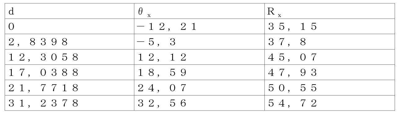
ここで、Rxは、次のようにモデリングすることができる。
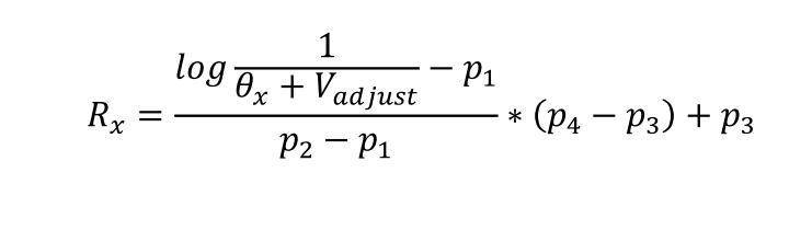
ここで、

である。
For R x and θ x , the following sample data values for the model above can be used.
where R x can be modeled as:
here,
is.
Vadjustは、シミュレーションによって得られる近似されたRx値と、システムによって計算されるRx値との誤差を最小化するための調整変数である。 V adjust is an adjustment variable to minimize the error between the approximated R x value obtained by simulation and the R x value calculated by the system.
上記から、因数c1~c5について次のような属性を作成することができる。
c1=p1
c2=Vadjust
c3=p2-p1
c4=p4-p3
c5=p3
From the above, the following attributes can be created for the factors c 1 -c 5 .
c 1 = p 1
c2 = V adjust
c 3 = p 2 - p 1
c 4 = p 4 - p 3
c5 = p3
本発明によるシステムで使用するc1~c5の値の適切な例は、次の通りであり得る。
c1=-2.31864756900365
c2=175.72
c3=0.105103250465988
c4=25.2
c5=22.16
Suitable examples of values for c 1 -c 5 for use in the system according to the invention may be as follows.
c 1 =-2.31864756900365
c2 = 175.72
c3 = 0.105103250465988
c4 = 25.2
c5 = 22.16
図3は、本発明によるシステムをセットアップして用いることができる1つの好ましい方法、言い替えれば、補正された磁場ベクトルに対応する投与量設定を計算するための方法、を略示するフローチャートである。任意選択である最初の3ステップでは、磁場測定手段、本例では磁力計m1およびm2、が、まず、直交する3軸x、yおよびzの全てに沿った全方向で定磁場に曝されることによって初期化され、各磁力計について、測定された基準値の配列が生成される:

次に、各測定値について、オフセットまたは感度因数が計算され、
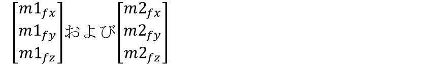
が得られる。
FIG. 3 is a flowchart outlining one preferred method by which a system according to the present invention can be set up and used, in other words for calculating dose settings corresponding to corrected magnetic field vectors. In the optional first three steps, the magnetic field measuring means, in this example magnetometers m1 and m2, are first exposed to a constant magnetic field in all directions along all three orthogonal axes x, y and z. to generate an array of measured reference values for each magnetometer, initialized by:
Then for each measurement an offset or sensitivity factor is calculated,
is obtained.
次に、これらのオフセット因数を用いて、測定された磁気値のオフセット、

および、
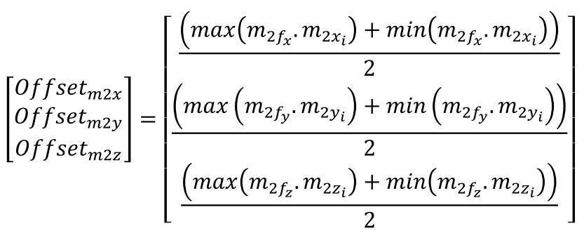
が計算される。
These offset factors are then used to offset the measured magnetic values,
and,
is calculated.
これらのオフセット値は、システム内、例えば一体式処理ユニットへ接続されるメモリストレージに、または一体式処理ユニットのレジスタ内に記憶される。磁場のオフセットの計算ステップについては、適切な磁力計を用いれば、こうした磁力計は、このような計算を考慮に入れて工場設定され得るという理由で、これを任意選択にすることも可能である。 These offset values are stored within the system, eg, in memory storage coupled to the integrated processing unit, or within registers of the integrated processing unit. The magnetic field offset calculation step may also be made optional, since with appropriate magnetometers such magnetometers may be factory set to take such calculations into account. .
投与量制御システムが起動されると、磁石が回転されかつ/または平行移動され、かつその間に磁場を生成し、3次元空間におけるその座標値が第1および第2の磁力計m1およびm2によって測定され、上記のように、値の配列、
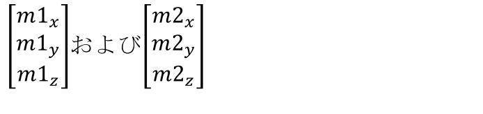
が得られる。
When the dose control system is activated, the magnet is rotated and/or translated and produces a magnetic field therebetween, whose coordinate values in three-dimensional space are measured by the first and second magnetometers m1 and m2. and, as above, an array of values,
is obtained.
m1およびm2について測定される値は、任意選択により、先に生成されるオフセット値を包含することによって、かつ磁力計の空間的方向性を考慮することによって補正されることが可能である。

次に、投影の等法線角度が、次式、
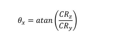
および、

を用いて計算される。
Then the isonormal angles of the projection are given by:
and,
is calculated using
本方法では、図3に示すように、特に軸x、yおよびzに近い値が読み取られる場合、逆正接関数atanおよびatan2の使用に基づく読み取り誤差を回避するために、任意選択のカットオフ計算ステップも包含されることが可能である。この目的に沿って、かつ計算を介するこのような誤差の増幅を回避するために、Rxは、下限および上限、各々RXlowおよびRXhigh、で切除される。このようなカットオフ値は、好ましくは、機能システムの動作限界において、各々関数min(θx)およびmax(θx)を介して取得することができる。 In the method, as shown in FIG. 3, an optional cut-off calculation A step can also be included. To this end, and to avoid amplifying such errors through computation, R x is truncated at lower and upper limits, RX low and RX high , respectively. Such cut-off values can be obtained via the functions min(θx) and max(θx), respectively, preferably at the operational limits of the functional system.
磁場擬似ベクトルCRは、投影の等法線投影平面内に収まるように、X軸を中心に回転され、次のようにCR2が生成される。

次に、CR2の値を用いて、磁石の回転角、および付随的に法線が、XZ平面上への投影により、次のように計算される。

次いで、これを用いて、法線を次式のように計算することができる。

This can then be used to calculate the normal as:
したがって、このような計算は、こうした情報がデバイスの動作にとって適切または必要である場合、薬物送達デバイスの長手方向軸に沿った正確な位置の決定も可能にする。 Such calculations therefore also allow determination of precise position along the longitudinal axis of the drug delivery device, if such information is appropriate or necessary for the operation of the device.
Claims (22)
前記薬物送達本体の前記近位端で前記回転可能な投与量設定ホイールに取り外し可能に取り付け可能な、または永久的に固定される略円板形の直径方向単一双極子磁石と、
前記薬物送達本体の前記近位端へ取り外し可能に取り付け可能なハウジングであって、前記取り外し可能に取り付け可能なハウジングは、
前記略円板形の直径方向単一双極子磁石により生成される磁場を測定するように構成される、少なくとも第1および第2の磁場測定手段を備える、取り外し可能に取り付け可能なハウジングと、
前記少なくとも第1および第2の磁場測定手段へ連結され、前記少なくとも第1および第2の磁場測定手段から受信される情報を処理するように構成される一体式制御ユニットと、を備え、
前記少なくとも第1および第2の磁場測定手段は、前記取り外し可能に取り付け可能なハウジング内に、前記薬物送達本体および前記略円板形の直径方向単一双極子磁石の長手方向軸に対して変位された軸方向関係で位置決めされ、
前記略円板形の直径方向単一双極子磁石は、前記薬物送達本体の前記長手方向軸の周りを前記回転可能な投与量設定ホイールと共回転するように構成され、
前記一体式制御ユニットは、前記少なくとも第1および第2の磁場測定手段により測定され、かつ前記少なくとも第1および第2の磁場測定手段と前記略円板形の直径方向単一双極子磁石との軸方向アラインメントの欠如から結果的に生じる磁場値を、前記少なくとも第1および第2の磁場測定手段により測定される測定磁場で構成されかつ前記測定磁場から計算される合成擬似磁場を表す擬似ベクトルへ直交する3軸x、yまたはzのうちの1つを中心とする回転を印加して前記合成擬似磁場を表す前記擬似ベクトルを等法線投影平面に収めることにより、補正するように構成され、
前記擬似ベクトルは、以下の式
CR=CMm1-CMm2=(CAm1+CE)-(CAm2+CE)=CAm1-CAm2
で定義される擬似結果磁場であり、
ここで、
CRは、結果的に生じる磁場擬似ベクトル、
CMm1は、前記第1の磁場測定手段により測定される磁場、
CMm2は、前記第2の磁場測定手段により測定される磁場、
CAm1は、前記第1の磁場測定手段により測定される、前記略円板形の直径方向単一双極子磁石により生成される実際の磁場、
CAm2は、前記第2の磁場測定手段により測定される、前記略円板形の直径方向単一双極子磁石により生成される実際の磁場、
CEは、外部磁場、
であり、
前記一体式制御ユニットは、さらに、
前記少なくとも第1および第2の磁場測定手段の前記変位された軸方向関係に関して正規化されたベクトルを提供するように構成され、前記正規化されたベクトルは、前記略円板形の直径方向単一双極子磁石の前記回転により生成されて前記少なくとも第1および第2の磁場測定手段の前記測定磁場から導出され、前記一体式制御ユニットは、さらに、前記正規化されたベクトルから投与量設定値を計算するように構成され、前記正規化されたベクトルは、以下の計算式
[数1]
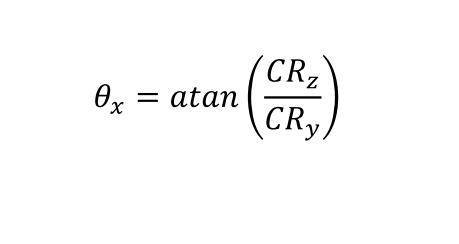
および、
[数2]
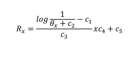
の適用により補正するように構成され、ここで、
R x は、単位度で表される角度であり、測定磁場の、好ましくはX軸である直交する1つの軸を中心とする回転による変換を有効化して、角ベクトルとして表される前記磁場を位置合わせし直し、よって、前記ベクトルは、その等法線投影平面と略同一平面となり、
θ x は、X軸を中心として測定される実際の回転角(単位度)であり、
c 1 =p 1 、
c 2 =V adjust 、
c 3 =p 2 -p 1 、
c 4 =p 4 -p 3 、
c 5 =p 3 、
であり、
R x は、各距離dのθ x 値についてモデリングされて、以下のようなd i 、θ xi およびR xi の値セットが得られ、
[数3]
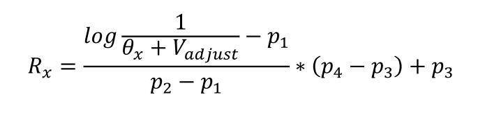
ここで、
[数4]
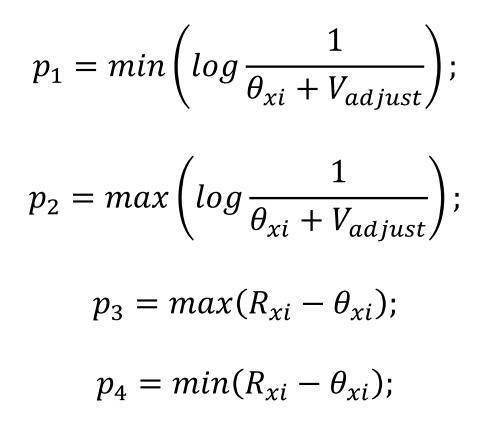
であり、
V adjust は、シミュレーションによって得られる近似されたR x 値と、前記システムによって計算されるR x 値との誤差を最小化するための調整変数であり、
前記一体式制御ユニットは、さらに、前記正規化されたベクトルから投与量設定値を計算するように構成される、投与量制御システム。 1. A dose control system configured for an injectable drug delivery device, said drug delivery device comprising an elongated drug delivery body having a distal end and a proximal end and at least one drug delivery body carried by said drug delivery body. a dose setting wheel positioned at a proximal end of the drug delivery body and rotatable about a longitudinal axis of the drug delivery body, the dose control system comprising:
a generally disk-shaped diametric single dipole magnet removably attachable to or permanently affixed to the rotatable dose setting wheel at the proximal end of the drug delivery body;
A housing removably attachable to the proximal end of the drug delivery body, the removably attachable housing comprising:
a removably attachable housing comprising at least first and second magnetic field measuring means configured to measure the magnetic field generated by said generally disc-shaped diametric single dipole magnet;
an integrated control unit coupled to said at least first and second magnetic field measuring means and configured to process information received from said at least first and second magnetic field measuring means;
Said at least first and second magnetic field measuring means are displaced within said removably attachable housing with respect to longitudinal axes of said drug delivery body and said generally disc-shaped diametric single dipole magnet. positioned in a fixed axial relationship,
the generally disc-shaped diametric single dipole magnet configured to co-rotate with the rotatable dose setting wheel about the longitudinal axis of the drug delivery body ;
Said integrated control unit is measured by said at least first and second magnetic field measuring means, and comprises said at least first and second magnetic field measuring means and said generally disc-shaped diametric single dipole magnet. field values resulting from the lack of axial alignment of the pseudo configured to correct by applying a rotation about one of three orthogonal axes x, y or z to the vector to fit the pseudo-vector representing the resultant pseudo-magnetic field to an isonormal projection plane. is ,
The pseudo-vector is expressed by the following formula
CR=CMm1-CMm2=(CAm1+CE)-(CAm2+CE)=CAm1-CAm2
is the pseudo resultant magnetic field defined by
here,
CR is the resulting magnetic field pseudovector;
CMm1 is the magnetic field measured by the first magnetic field measuring means;
CMm2 is the magnetic field measured by the second magnetic field measuring means;
CAm1 is the actual magnetic field produced by the generally disc-shaped diametric single dipole magnet, as measured by the first magnetic field measuring means;
CAm2 is the actual magnetic field produced by the substantially disc-shaped diametric single dipole magnet, as measured by the second magnetic field measuring means;
CE is the external magnetic field;
and
The integrated control unit further comprises:
configured to provide a normalized vector with respect to said displaced axial relationship of said at least first and second magnetic field measuring means, said normalized vector being a diametrical unit of said generally disk-shaped Derived from the measured magnetic fields of the at least first and second magnetic field measuring means generated by the rotation of a single dipole magnet, the integrated control unit further calculates a dose setpoint from the normalized vector. and said normalized vector is calculated according to the following formula
[Number 1]
and,
[Number 2]
is configured to compensate by the application of, where:
R x is an angle expressed in degrees, enabling transformation of the measured magnetic field by rotation about one orthogonal axis, preferably the X axis, to yield said magnetic field expressed as an angular vector realign so that the vector is approximately coplanar with its isonormal projection plane;
θ x is the actual rotation angle (in degrees) measured about the X axis;
c 1 =p 1 ,
c 2 = V adjust ,
c 3 =p 2 -p 1 ,
c 4 =p 4 -p 3 ,
c5 = p3 , _
and
R x is modeled for the θ x value for each distance d to obtain a set of values for d i , θ xi and R xi as follows:
[Number 3]
here,
[Number 4]
and
V adjust is an adjustment variable to minimize the error between the approximated R x value obtained by simulation and the R x value calculated by the system ;
A dose control system , wherein the integrated control unit is further configured to calculate a dose setpoint from the normalized vector .
[数5]

を介して計算するように構成され、ここで、x、y、zは、磁場の直交する3軸であり、
xi、yiおよびziは、前記測定磁場の対応するベクトルにより生成される、3次元における点のクラウドに似た一連の点であり、前記点のクラウドは、因数、
[数6]

によってスフェリサイズ(sphericize)される、請求項1~8のいずれか一項に記載の投与量制御システム。 The integrated control unit further determines the offset values of the at least first and second magnetic field measuring means by:
[Number 5]
where x, y, z are the three orthogonal axes of the magnetic field;
x i , y i and z i are a series of points similar to a point cloud in three dimensions generated by the corresponding vectors of said measured magnetic field, said point cloud being a factor,
[Number 6]
A dose control system according to any one of claims 1 to 8, which is sphericized by
[数7]

を介して補正するように構成される、請求項9に記載の投与量制御システム。 The integrated control unit further determines the magnetic offset value as:
[Number 7]
10. The dose control system of claim 9, configured to compensate via
回転可能な略円板形の直径方向単一双極子磁石により生成される磁場(CM)を、前記略円板形の直径方向単一双極子磁石の回転軸に対して変位される軸方向アラインメントで配置される少なくとも第1の磁力計(m1)および第2の磁力計(m2)によって測定するステップと、
結果的に生じる磁場擬似ベクトル(CR)を計算するステップと、
任意選択により、前記測定された磁場CMm1およびCMm2を補正するステップと、
前記磁場擬似ベクトルについて、投影の等法線平面に対する回転角を計算するステップと、
前記回転角を有する前記磁場擬似ベクトルを変換して、回転および投影により、等法線が補正された磁場擬似ベクトル(CR2)を生成するステップと、
前記等法線が補正された磁場擬似ベクトルから、前記回転軸を中心とする前記略円板形の直径方向単一双極子磁石の回転角を計算するステップとを含む、投与量設定を計算するための方法。 A method for calculating dose settings in a dose control system according to any one of claims 1-20, comprising:
an axial alignment in which the magnetic field (CM) generated by a rotatable generally disk-shaped diametrical single dipole magnet is displaced with respect to the axis of rotation of said generally disk-shaped diametrical single dipole magnet; measuring by at least a first magnetometer (m 1 ) and a second magnetometer (m 2 ) arranged at
calculating the resulting magnetic field pseudovector (CR);
optionally correcting the measured magnetic fields CMm1 and CMm2;
calculating a rotation angle for the magnetic field pseudovector with respect to the isonormal plane of the projection;
transforming the magnetic field pseudo-vector with the rotation angle to generate an isonormal corrected magnetic field pseudo-vector (CR2) by rotation and projection;
calculating the angle of rotation of the generally disc-shaped diametric single dipole magnet about the axis of rotation from the isonormal corrected magnetic field pseudovectors. way for.
Priority Applications (1)
| Application Number | Priority Date | Filing Date | Title |
|---|---|---|---|
| JP2021213678A JP7455107B2 (en) | 2017-01-25 | 2021-12-28 | Dose control systems and related methods of use for injectable drug delivery devices |
Applications Claiming Priority (1)
| Application Number | Priority Date | Filing Date | Title |
|---|---|---|---|
| PCT/IB2017/000306 WO2018138542A1 (en) | 2017-01-25 | 2017-01-25 | Dose control system for injectable-drug delivery devices and associated methods of use |
Related Child Applications (1)
| Application Number | Title | Priority Date | Filing Date |
|---|---|---|---|
| JP2021213678A Division JP7455107B2 (en) | 2017-01-25 | 2021-12-28 | Dose control systems and related methods of use for injectable drug delivery devices |
Publications (2)
| Publication Number | Publication Date |
|---|---|
| JP2020507429A JP2020507429A (en) | 2020-03-12 |
| JP7204672B2 true JP7204672B2 (en) | 2023-01-16 |
Family
ID=58530581
Family Applications (2)
| Application Number | Title | Priority Date | Filing Date |
|---|---|---|---|
| JP2019560497A Active JP7204672B2 (en) | 2017-01-25 | 2017-01-25 | Injectable drug delivery device dosage control system and associated method of use |
| JP2021213678A Active JP7455107B2 (en) | 2017-01-25 | 2021-12-28 | Dose control systems and related methods of use for injectable drug delivery devices |
Family Applications After (1)
| Application Number | Title | Priority Date | Filing Date |
|---|---|---|---|
| JP2021213678A Active JP7455107B2 (en) | 2017-01-25 | 2021-12-28 | Dose control systems and related methods of use for injectable drug delivery devices |
Country Status (7)
| Country | Link |
|---|---|
| US (2) | US12102807B2 (en) |
| EP (1) | EP3573687A1 (en) |
| JP (2) | JP7204672B2 (en) |
| KR (1) | KR102681955B1 (en) |
| CN (1) | CN110430905B (en) |
| MX (1) | MX2019008559A (en) |
| WO (1) | WO2018138542A1 (en) |
Families Citing this family (13)
| Publication number | Priority date | Publication date | Assignee | Title |
|---|---|---|---|---|
| LT3589340T (en) | 2017-02-28 | 2026-01-12 | Eli Lilly And Company | Dose detection and drug identification for a medication delivery device |
| JP7204688B2 (en) | 2017-06-09 | 2023-01-16 | サノフイ | Electronics for dose sensing |
| JP7222985B2 (en) | 2017-09-22 | 2023-02-15 | ノボ・ノルデイスク・エー/エス | Accessory device for drug delivery device |
| DK3709888T3 (en) | 2017-11-14 | 2024-11-25 | Sanofi Sa | INTEGRATION OF AN ULTRASOUND SENSOR IN AN INJECTION DEVICE PISTON STOPPER |
| WO2019096726A2 (en) | 2017-11-14 | 2019-05-23 | Sanofi | Conserving power in an injection device |
| EP3720525A1 (en) | 2017-12-04 | 2020-10-14 | Novo Nordisk A/S | Drug delivery system with multipolar magnet and sensor system |
| DK3755403T3 (en) | 2018-02-22 | 2024-09-23 | Lilly Co Eli | DRUG DELIVERY DEVICE WITH A REGISTERED ELEMENT |
| CN113164690B (en) | 2018-12-04 | 2023-12-22 | 诺和诺德股份有限公司 | Drug delivery components with mobile sensor systems |
| CN113226409A (en) | 2018-12-19 | 2021-08-06 | 赛诺菲 | Optical configuration of medicament reservoir of drug delivery device |
| US12370321B2 (en) | 2019-07-01 | 2025-07-29 | Sanofi | Awakening electronics in an injection device |
| JP7723081B2 (en) | 2020-10-13 | 2025-08-13 | バイオコープ プロダクション ソシエテ パ アクシオンス シンプリフィエ | Infusion monitoring module with magnetic rotation sensing. |
| EP4122513A1 (en) * | 2021-07-22 | 2023-01-25 | Ypsomed AG | Improved actuating arrangement for a pen |
| JP7829715B2 (en) | 2022-03-31 | 2026-03-13 | バイオコープ プロダクション ソシエテ パ アクシオンス シンプリフィエ | Injection monitoring module with position locking system |
Citations (4)
| Publication number | Priority date | Publication date | Assignee | Title |
|---|---|---|---|---|
| JP2012519025A (en) | 2009-02-27 | 2012-08-23 | ライフスキャン・インコーポレイテッド | Medical module for drug delivery pen |
| JP2012533058A (en) | 2009-07-07 | 2012-12-20 | ムービング マグネット テクノロジーズ | Multi-period absolute position detector |
| JP2014531283A (en) | 2011-10-07 | 2014-11-27 | ノボ・ノルデイスク・エー/エス | System for determining the position of an element based on a three-axis magnetic sensor |
| WO2015158230A1 (en) | 2014-04-14 | 2015-10-22 | 江苏多维科技有限公司 | Micro guiding screw pump using magnetic resistance sensor and manufacturing method therefor |
Family Cites Families (14)
| Publication number | Priority date | Publication date | Assignee | Title |
|---|---|---|---|---|
| WO2002064196A1 (en) | 2001-02-14 | 2002-08-22 | Novo Nordisk A/S | Electronically controlled injection or infusion device |
| US6929619B2 (en) * | 2002-08-02 | 2005-08-16 | Liebel-Flarshiem Company | Injector |
| DE10330984B4 (en) | 2003-07-09 | 2009-12-10 | Tecpharma Licensing Ag | Injection device with position sensor |
| DE10330986B4 (en) | 2003-07-09 | 2010-01-07 | Tecpharma Licensing Ag | Non-contact scanning with magnetoresistive sensor |
| EP2011223B1 (en) * | 2006-04-12 | 2018-06-13 | Novo Nordisk A/S | Absolute position determination of movably mounted member in medication delivery device |
| JP5728231B2 (en) | 2007-12-31 | 2015-06-03 | ノボ・ノルデイスク・エー/エス | Electronic monitoring injection device |
| KR101939267B1 (en) | 2010-07-21 | 2019-01-16 | 삼성전자주식회사 | Method and device for measuring dose in injector |
| EP2866862B1 (en) * | 2012-06-27 | 2016-05-04 | Sanofi-Aventis Deutschland GmbH | Drug delivery device |
| US10105497B2 (en) | 2013-04-05 | 2018-10-23 | Novo Nordisk A/S | Drug delivery device with integrated magnetic movement indicator |
| DK2981310T3 (en) | 2013-04-05 | 2017-10-16 | Novo Nordisk As | Dose monitoring apparatus for a drug delivery apparatus |
| CN203802882U (en) * | 2014-04-14 | 2014-09-03 | 江苏多维科技有限公司 | Micro guiding screw pump with magnetic resistance sensor |
| US10704944B2 (en) * | 2014-09-14 | 2020-07-07 | Becton, Dickinson And Company | System and method for capturing dose information |
| EP3058970A1 (en) * | 2015-02-19 | 2016-08-24 | Sanofi-Aventis Deutschland GmbH | Data collection device for attachment to an injection device |
| PT3419700T (en) * | 2015-07-21 | 2023-12-12 | Biocorp Production SA | Dose control device for injectable-drug delivery devices |
-
2017
- 2017-01-25 JP JP2019560497A patent/JP7204672B2/en active Active
- 2017-01-25 KR KR1020197024396A patent/KR102681955B1/en active Active
- 2017-01-25 US US16/479,782 patent/US12102807B2/en active Active
- 2017-01-25 EP EP17716594.1A patent/EP3573687A1/en active Pending
- 2017-01-25 WO PCT/IB2017/000306 patent/WO2018138542A1/en not_active Ceased
- 2017-01-25 CN CN201780088521.9A patent/CN110430905B/en active Active
- 2017-01-25 MX MX2019008559A patent/MX2019008559A/en unknown
-
2021
- 2021-12-28 JP JP2021213678A patent/JP7455107B2/en active Active
-
2024
- 2024-08-12 US US18/800,828 patent/US20240399068A1/en active Pending
Patent Citations (4)
| Publication number | Priority date | Publication date | Assignee | Title |
|---|---|---|---|---|
| JP2012519025A (en) | 2009-02-27 | 2012-08-23 | ライフスキャン・インコーポレイテッド | Medical module for drug delivery pen |
| JP2012533058A (en) | 2009-07-07 | 2012-12-20 | ムービング マグネット テクノロジーズ | Multi-period absolute position detector |
| JP2014531283A (en) | 2011-10-07 | 2014-11-27 | ノボ・ノルデイスク・エー/エス | System for determining the position of an element based on a three-axis magnetic sensor |
| WO2015158230A1 (en) | 2014-04-14 | 2015-10-22 | 江苏多维科技有限公司 | Micro guiding screw pump using magnetic resistance sensor and manufacturing method therefor |
Also Published As
| Publication number | Publication date |
|---|---|
| JP7455107B2 (en) | 2024-03-25 |
| CN110430905A (en) | 2019-11-08 |
| BR112019015045A2 (en) | 2020-03-10 |
| CA3051323A1 (en) | 2018-08-02 |
| KR102681955B1 (en) | 2024-07-04 |
| JP2020507429A (en) | 2020-03-12 |
| WO2018138542A1 (en) | 2018-08-02 |
| US12102807B2 (en) | 2024-10-01 |
| KR20190109474A (en) | 2019-09-25 |
| CN110430905B (en) | 2022-07-12 |
| US20240399068A1 (en) | 2024-12-05 |
| EP3573687A1 (en) | 2019-12-04 |
| JP2022046692A (en) | 2022-03-23 |
| US20210330892A1 (en) | 2021-10-28 |
| MX2019008559A (en) | 2019-11-11 |
Similar Documents
| Publication | Publication Date | Title |
|---|---|---|
| JP7455107B2 (en) | Dose control systems and related methods of use for injectable drug delivery devices | |
| US12220565B2 (en) | Dose control system for injectable-drug delivery devices and associated methods of use | |
| US11511045B2 (en) | Dose control device for injectable-drug delivery devices | |
| US12070585B2 (en) | Dose control device for injectable-drug delivery devices | |
| CA3051323C (en) | Dose control system for injectable-drug delivery devices and associated methods of use | |
| JP7482964B2 (en) | Dose control system for injectable drug delivery devices and related methods of use - Patents.com | |
| BR112019015045B1 (en) | DOSE CONTROL SYSTEM AND METHOD FOR CALCULATING A DOSE ADJUSTMENT | |
| BR112020018521B1 (en) | DOSE CONTROL DEVICE FOR AN INJECTABLE DRUG RELEASE DEVICE | |
| BR112018001205B1 (en) | DOSE CONTROL SYSTEM ADAPTED FOR AN INJECTABLE DRUG DELIVERY DEVICE AND METHOD FOR IMPROVING TREATMENT OBSERVANCE IN AN INJECTABLE DRUG ADMINISTRATION REGIMEN |
Legal Events
| Date | Code | Title | Description |
|---|---|---|---|
| A621 | Written request for application examination |
Free format text: JAPANESE INTERMEDIATE CODE: A621 Effective date: 20200124 |
|
| A131 | Notification of reasons for refusal |
Free format text: JAPANESE INTERMEDIATE CODE: A131 Effective date: 20201222 |
|
| A977 | Report on retrieval |
Free format text: JAPANESE INTERMEDIATE CODE: A971007 Effective date: 20201225 |
|
| A601 | Written request for extension of time |
Free format text: JAPANESE INTERMEDIATE CODE: A601 Effective date: 20210322 |
|
| A601 | Written request for extension of time |
Free format text: JAPANESE INTERMEDIATE CODE: A601 Effective date: 20210524 |
|
| A02 | Decision of refusal |
Free format text: JAPANESE INTERMEDIATE CODE: A02 Effective date: 20210831 |
|
| A521 | Request for written amendment filed |
Free format text: JAPANESE INTERMEDIATE CODE: A523 Effective date: 20211228 |
|
| C60 | Trial request (containing other claim documents, opposition documents) |
Free format text: JAPANESE INTERMEDIATE CODE: C60 Effective date: 20211228 |
|
| A521 | Request for written amendment filed |
Free format text: JAPANESE INTERMEDIATE CODE: A821 Effective date: 20211228 |
|
| A911 | Transfer to examiner for re-examination before appeal (zenchi) |
Free format text: JAPANESE INTERMEDIATE CODE: A911 Effective date: 20220121 |
|
| C21 | Notice of transfer of a case for reconsideration by examiners before appeal proceedings |
Free format text: JAPANESE INTERMEDIATE CODE: C21 Effective date: 20220125 |
|
| A912 | Re-examination (zenchi) completed and case transferred to appeal board |
Free format text: JAPANESE INTERMEDIATE CODE: A912 Effective date: 20220311 |
|
| C211 | Notice of termination of reconsideration by examiners before appeal proceedings |
Free format text: JAPANESE INTERMEDIATE CODE: C211 Effective date: 20220315 |
|
| C22 | Notice of designation (change) of administrative judge |
Free format text: JAPANESE INTERMEDIATE CODE: C22 Effective date: 20220511 |
|
| C13 | Notice of reasons for refusal |
Free format text: JAPANESE INTERMEDIATE CODE: C13 Effective date: 20220622 |
|
| A521 | Request for written amendment filed |
Free format text: JAPANESE INTERMEDIATE CODE: A523 Effective date: 20220916 |
|
| C23 | Notice of termination of proceedings |
Free format text: JAPANESE INTERMEDIATE CODE: C23 Effective date: 20221109 |
|
| C03 | Trial/appeal decision taken |
Free format text: JAPANESE INTERMEDIATE CODE: C03 Effective date: 20221206 |
|
| C30A | Notification sent |
Free format text: JAPANESE INTERMEDIATE CODE: C3012 Effective date: 20221206 |
|
| A61 | First payment of annual fees (during grant procedure) |
Free format text: JAPANESE INTERMEDIATE CODE: A61 Effective date: 20221228 |
|
| R150 | Certificate of patent or registration of utility model |
Ref document number: 7204672 Country of ref document: JP Free format text: JAPANESE INTERMEDIATE CODE: R150 |
|
| S533 | Written request for registration of change of name |
Free format text: JAPANESE INTERMEDIATE CODE: R313533 |
|
| R350 | Written notification of registration of transfer |
Free format text: JAPANESE INTERMEDIATE CODE: R350 |
|
| R250 | Receipt of annual fees |
Free format text: JAPANESE INTERMEDIATE CODE: R250 |