JP7219085B2 - Lamp units, vehicle lighting systems - Google Patents
Lamp units, vehicle lighting systems Download PDFInfo
- Publication number
- JP7219085B2 JP7219085B2 JP2018244927A JP2018244927A JP7219085B2 JP 7219085 B2 JP7219085 B2 JP 7219085B2 JP 2018244927 A JP2018244927 A JP 2018244927A JP 2018244927 A JP2018244927 A JP 2018244927A JP 7219085 B2 JP7219085 B2 JP 7219085B2
- Authority
- JP
- Japan
- Prior art keywords
- vehicle
- light
- dark boundary
- boundary line
- bright
- Prior art date
- Legal status (The legal status is an assumption and is not a legal conclusion. Google has not performed a legal analysis and makes no representation as to the accuracy of the status listed.)
- Active
Links
Images



Landscapes
- Lighting Device Outwards From Vehicle And Optical Signal (AREA)
Description
本発明は、多様な照射パターンによる光照射を行う車両用灯具の改良技術に関する。 TECHNICAL FIELD The present invention relates to an improved technique for a vehicle lamp that irradiates light with various irradiation patterns.
夜間に車両を走行させる際には、基本的に前照灯によりロービームとハイビームを照射することにより車両の前方の視認性を確保する。しかしながら、いわゆるカットオフラインより上側に光を照射すると、対向車や先行車(以下、これらを「前方車両」という。)、あるいは歩行者が存在する場合に、それらにグレアを与えるおそれがあるので、すれ違い時にはハイビームが非照射に切り替えられる。また、近年では、前方車両や歩行者の位置を検出し、これらにグレアを与えないようにハイビームの配光パターンを可変に制御する技術が種々提案されている(例えば、特開2010-232081号公報参照)。 When driving a vehicle at night, visibility in front of the vehicle is basically ensured by illuminating the low beam and high beam from the headlights. However, if the light is emitted above the so-called cut-off line, there is a risk of giving glare to oncoming vehicles, preceding vehicles (hereinafter referred to as "front vehicles"), or pedestrians, if they are present. When passing each other, the high beam is switched to non-irradiation. In recent years, various techniques have been proposed for detecting the positions of vehicles and pedestrians in front and variably controlling the light distribution pattern of the high beam so as not to give glare to them (for example, Japanese Patent Laid-Open No. 2010-232081). Gazette).
従前、上記のような配光パターンの制御は、光源とその光を部分的に遮る遮蔽板を組み合わせることで実現されていたが、この場合、設置可能な遮蔽板の数には限りがあり、照射パターンを多様に制御することは難しかった。これに対し、例えば、LEDなどの発光素子をマトリクス状にした光源を用いて、各発光素子を個別に点消灯させてそれらの光により形成される像をレンズによって車両前方へ投影する方式や、矩形状の画素がマトリクス状に配置されたドットマトリクス方式の液晶素子を用いて光源からの光を選択的に透過(又は反射)させることによって像を形成し、その像をレンズによって車両前方へ投影する方式なども知られている。これらの方式によれば、配光パターンを多様に制御することができる。 Previously, the control of the light distribution pattern as described above was realized by combining a light source with a shielding plate that partially blocks the light. It was difficult to control various irradiation patterns. On the other hand, for example, a method of using a light source in which light-emitting elements such as LEDs are arranged in a matrix, individually turning on and off each light-emitting element, and projecting an image formed by the light to the front of the vehicle through a lens, An image is formed by selectively transmitting (or reflecting) light from a light source using a dot-matrix liquid crystal element in which rectangular pixels are arranged in a matrix, and the image is projected forward of the vehicle through a lens. A method for doing so is also known. According to these methods, the light distribution pattern can be controlled in various ways.
ところで、例えば自車両の左側の道路脇において歩行者が自車両へ近づくように移動する場合を考えると、その頭部の見かけの位置は徐々に斜め上方向へ変化し、かつ見かけの大きさも徐々に大きくなる。このような歩行者に対して、上記した各方式では、頭部に対しては減光または非照射とし、体に対しては照射とするように配光パターンが制御される。このとき、上記した各方式においては、水平方向および垂直方向に沿って配列される複数のセグメント(配光領域)のそれぞれにおける光強度(照度)を制御することによって配光パターンに対応する像が形成される。 By the way, for example, when a pedestrian moves toward the vehicle on the left side of the vehicle, the apparent position of the pedestrian's head gradually changes diagonally upward, and the apparent size of the pedestrian gradually changes. grow to For such pedestrians, in each of the above methods, the light distribution pattern is controlled so that the head is dimmed or non-illuminated, and the body is illuminated. At this time, in each of the above methods, an image corresponding to the light distribution pattern is produced by controlling the light intensity (illuminance) in each of a plurality of segments (light distribution regions) arranged along the horizontal and vertical directions. It is formed.
しかし、各セグメントの境界は水平方向および垂直方向に沿って存在するので、各セグメントにより形成される像の輪郭において斜め線は階段状に表現される。このとき、各セグメントの解像度が比較的に低い場合には、歩行者の見かけの位置や大きさの変化に対する追従性が低下する。それにより、歩行者の頭部へのグレアを確実に回避するために減光または非照射とすべきセグメントの数が増えてしまうため、歩行者の視認性が低下する可能性がある。 However, since the boundaries of each segment exist along the horizontal and vertical directions, diagonal lines appear stepped in the outline of the image formed by each segment. At this time, if the resolution of each segment is relatively low, the ability to follow changes in the apparent position and size of the pedestrian is reduced. This can reduce pedestrian visibility as more segments must be dimmed or non-illuminated to reliably avoid glare to the pedestrian's head.
他方、各セグメントの解像度を高くした場合には上記不都合が解消し得る。しかし、この場合には、例えば発光素子を用いる方式であればより多くの発光素子とそれらを駆動する回路が必要となるため、構成の複雑化並びにコスト増を招く。液晶素子を用いる方式においても同様であり、より多くの画素とそれらを駆動する回路が必要となるため、構成の複雑化並びにコスト増を招く。 On the other hand, if the resolution of each segment is increased, the above inconvenience can be resolved. However, in this case, for example, if the method uses light emitting elements, more light emitting elements and circuits for driving them are required, resulting in a complicated configuration and an increase in cost. The same is true for the method using a liquid crystal element, and more pixels and circuits for driving them are required, resulting in a complicated configuration and an increase in cost.
本発明に係る具体的態様は、構成の複雑化並びにコスト増を招くことなく、歩行者への追従性の高い配光パターンを実現し得る技術を提供することを目的の1つとする。 A specific aspect of the present invention aims to provide a technique capable of realizing a light distribution pattern that is highly followable to pedestrians without complicating the configuration and increasing the cost.
[1]本発明に係る一態様の車両用灯具システムは、(a)自車両の前方へ光照射を行うための車両用灯具システムであって、(b)選択的な光照射を実行可能なランプユニットと、(c)前記ランプユニットの動作を制御する制御装置と、を含み、(d)前記制御
装置は、前記自車両の前方に歩行者が存在する場合に、前記自車両の車幅方向の中央を基準にした左前方又は右前方の少なくとも一方に対して、当該中央から離れるほど鉛直方向の高さが高くなるように傾斜した明暗境界線を含む配光パターンであって当該明暗境界線の上側領域が相対的に暗く下側領域が相対的に明るい配光パターンを前記ランプユニットに形成させるものであり、(e)前記ランプユニットは、前記配光パターンにおける前記明暗境界線として、前記自車両の左前方において当該自車両側から見て左上がりに傾斜する第1明暗境界線と、前記自車両の右前方において当該自車両側から見て右上がりに形成される第2明暗境界線とを形成可能に構成されているとともに、前記第1明暗境界線と前記第2明暗境界線のそれぞれの傾斜角度を切り替え可能に構成されており、(f)前記制御装置は、前記第1明暗境界線と前記第2明暗境界線のうち前記自車両の通行帯として設定されている側に配置されるものの前記傾斜角度が相対的に大きくなるように前記ランプユニットを制御して前記配光パターンを形成させる、車両用灯具システムである。
[2]本発明に係る一態様の車両用灯具システムの制御方法は、(a)選択的な光照射を実行可能なランプユニットと当該ランプユニットの動作を制御する制御装置とを含み、自車両の前方へ光照射を行う車両用灯具システムにおける制御方法であって、(b)前記制御装置が、前記自車両の前方に歩行者が存在する場合に、前記自車両の車幅方向の中央を基準にした左前方又は右前方の少なくとも一方に対して、当該中央から離れるほど鉛直方向の高さが高くなるように傾斜した明暗境界線を含む配光パターンであって当該明暗境界線の上側領域が相対的に暗く下側領域が相対的に明るい配光パターンを前記ランプユニットに形成させるものであって、(c)前記ランプユニットは、前記配光パターンにおける前記明暗境界線として、前記自車両の左前方において当該自車両側から見て左上がりに傾斜する第1明暗境界線と、前記自車両の右前方において当該自車両側から見て右上がりに形成される第2明暗境界線とを形成可能に構成されているとともに、前記第1明暗境界線と前記第2明暗境界線のそれぞれの傾斜角度を切り替え可能に構成されており、(d)前記制御装置は、前記第1明暗境界線と前記第2明暗境界線のうち前記自車両の通行帯として設定されている側に配置されるものの前記傾斜角度が相対的に大きくなるように前記ランプユニットを制御して前記配光パターンを形成させる、車両用灯具システムの制御方法である。
[1] A vehicle lighting system according to one aspect of the present invention is (a) a vehicle lighting system for radiating light forward of a vehicle, and (b) capable of selectively radiating light. (c) a control device for controlling the operation of the lamp unit; A light distribution pattern including a light-dark boundary line slanted with respect to at least one of the left front or right front with respect to the center of the direction so that the height in the vertical direction increases as the distance from the center is increased, and the light-dark boundary (e) the lamp unit forms a light distribution pattern in which the area above the line is relatively dark and the area below the line is relatively bright; A first bright-dark boundary line that slopes upward to the left when viewed from the own vehicle side at the left front of the own vehicle, and a second bright-dark boundary formed at the right front of the own vehicle and upward to the right when viewed from the own vehicle side. (f) the control device is configured to be able to form a line and to be able to switch the inclination angles of each of the first bright-dark boundary line and the second bright-dark boundary line; The light distribution is performed by controlling the lamp unit so that the angle of inclination of the light-dark boundary line and the second light-dark boundary line, which is arranged on the side set as the traffic lane for the own vehicle, becomes relatively large. A vehicle lighting system that forms a pattern .
[2] A control method for a vehicle lighting system according to one aspect of the present invention includes: (a) a lamp unit capable of executing selective light irradiation; (b) when a pedestrian exists in front of the vehicle, the control device controls the center of the vehicle in the vehicle width direction. A light distribution pattern including a light-dark boundary line inclined so that the height in the vertical direction increases with distance from the center with respect to at least one of the left front or right front as a reference, and the upper area of the light-dark boundary line (c) the lamp unit forms a light distribution pattern in which the lower region is relatively dark and the lower region is relatively bright, and A first light-dark boundary line that slopes upward to the left when viewed from the own vehicle side on the left front of the vehicle, and a second light-dark boundary line that is formed on the right front of the vehicle and rises to the right when viewed from the own vehicle side. (d) the control device is configured to be able to form the first bright-dark boundary line and the inclination angle of each of the second bright-dark boundary line; and the light distribution pattern is formed by controlling the lamp unit so that the angle of inclination of the second light-dark boundary line, which is arranged on the side set as the traffic zone for the own vehicle, becomes relatively large. This is a control method for a vehicle lamp system that allows
上記構成によれば、構成の複雑化並びにコスト増を招くことなく、歩行者への追従性の高い配光パターンを実現し得る。 According to the above configuration, it is possible to realize a light distribution pattern that is highly followable to pedestrians without complicating the configuration and increasing costs.
図1は、一実施形態の車両用灯具システムの構成を示す図である。図1に示す車両用灯具システムは、自車両の前方へ光照射を行うための車両用灯具システムであり、選択的な光照射を実行可能なランプユニット1と、ランプユニットの動作を制御する制御装置2を含んで構成されている。ランプユニット1は、光源11、リフレクタ(反射集光部材)12、液晶素子13、一対の偏光板14a、14b、投影レンズ15を含んで構成されている。制御装置2は、撮像ユニット21、配光制御部22、液晶駆動部23、地図データベース(DB)24、GPSセンサ25を含んで構成されている。この車両用灯具システムは、撮像ユニット21によって撮影される画像に基づいて自車両の周囲に存在する前方車両や歩行者等の位置を検出し、前方車両等の位置に応じて設定される一定範囲を減光範囲(又は非照射範囲)に設定し、それ以外の範囲を光照射範囲に設定して選択的な光照射を行うためのものである。
FIG. 1 is a diagram showing the configuration of a vehicle lamp system according to one embodiment. The vehicle lighting system shown in FIG. 1 is a vehicle lighting system for radiating light forward of the own vehicle. It is configured including a
光源11は、例えば青色光を放出する発光素子(LED)に黄色蛍光体を組み合わせて構成された白色光LEDを含んで構成されている。光源11は、例えば、マトリクス状あるいはライン状に配列された複数の白色光LEDを備える。なお、光源11としてはLEDのほかに、レーザー、さらには電球や放電灯など車両用ランプユニットに一般的に使用されている光源が使用可能である。光源11の点消灯状態は配光制御部22によって制御される。
The
リフレクタ12は、光源11から出射する光を反射および集光し、偏光板14aを介して液晶素子(液晶パネル)13に入射させる。なお、光源11からリフレクタ12を介して液晶素子13へ至る光路上に他の光学系(例えば、レンズや反射鏡、さらにはそれらを組み合わせたもの)が存在してもよい。
The
液晶素子13は、それぞれ個別に制御可能な複数の画素領域(光変調領域)を有しており、液晶駆動部23によって与えられる液晶層への印加電圧の大きさに応じて各画素領域での液晶配向状態が可変に設定される。この液晶素子13に、偏光板14aを介して光源11からの光が照射され、透過光が偏光板14bを通過することにより、上記した光照射範囲と減光範囲に対応した明暗を有する像が形成される。例えば、液晶素子13は、垂直配向型の液晶層を備えるものであり、一対の偏光板14a、14bの間に配置されており、液晶層への電圧が無印加(あるいは閾値以下の電圧)である場合に透過率が極めて低い状態(遮光状態)となり、液晶層へ電圧が印加された場合に透過率が相対的に高い状態(透過状態)となるものである。
The
一対の偏光板14a、14bは、例えば互いの偏光軸を略直交させており、液晶素子13を挟んで対向配置されている。本実施形態では、液晶層に電圧無印加としているときに光が遮光される(透過率が極めて低くなる)動作モードであるノーマリーブラックモードを想定する。各偏光板14a、14bとしては、例えば一般的な有機材料(ヨウ素系、染料系)からなる吸収型偏光板を用いることができる。また、耐熱性を重視したい場合には、ワイヤーグリッド型偏光板を用いることも好ましい。ワイヤーグリッド型偏光板とはアルミニウム等の金属による極細線を配列してなる偏光板である。また、吸収型偏光板とワイヤーグリッド型偏光板を重ねて用いてもよい。
The pair of polarizing
投影レンズ15は、液晶素子13を透過する光によって形成される像(光照射範囲と減光範囲に対応した明暗を有する像)を広げて自車両の前方へ投影することにより配光パターンを形成するものであり、適宜設計されたレンズが用いられる。本実施形態では、反転投影型のプロジェクターレンズが用いられる。
The
撮像ユニット21は、カメラおよび画像処理部を含んで構成されており、自車両の前方を撮影し、その画像に基づいて所定の画像認識処理を行うことによって前方車両や歩行者の位置、距離、大きさ等を検出する。この撮像ユニット21は、自車両の所定位置(例えば、フロントガラス内側上部)に配置されている。なお、他の用途(例えば、自動ブレーキシステム等)のためのカメラが自車両に備わっている場合にはそのカメラを共用してもよい。
The
配光制御部22は、撮像ユニット21によって検出された前方車両等の位置に対応した光照射範囲および減光範囲を含む配光パターンを設定してその配光パターンに対応した像を形成するための制御信号を生成して液晶駆動部23へ供給する。この配光制御部23は、例えばCPU、ROM、RAM等を有するコンピュータシステムにおいて所定の動作プログラムを実行させることによって実現される。
The light
液晶駆動部23は、配光制御部22から供給される制御信号に基づいて液晶素子13へ駆動電圧を供給することにより、液晶素子13の各画素領域における液晶層の配向状態を個別に制御するものである。
The liquid
地図DB24は、道路の属性に関する情報や各種施設に関する情報などを含む地図データを格納するものである。道路の属性に関する情報には、例えば道路種別(高速道、国道、県道、市道など)や、車線数、制限速度などの情報が含まれている。なお、車両に地図DBを有する他のシステム(例えば、カーナビゲーションシステムなど)が備わっている場合には、そのシステムを地図DB24として用いてもよい。また、スマートフォン等の無線通信機器を介して地図DBを随時取得できる場合には、その無線通信機器を地図DB24として代用してもよい。
The
GPSセンサ25は、全地球測位システム(Global Positioning System)を利用して自車両の現在位置を検出する。なお、GPSセンサを有する他のシステム(例えば、カーナビゲーションシステムなど)が自車両に備わっている場合には、そのシステムをGPSセンサ25として代用してもよい。また、GPSセンサを備えたスマートフォン等の無線通信機器をGPSセンサ25として代用してもよい。
The
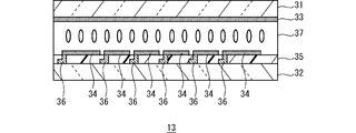
図2は、液晶素子の構成を示す模式的な断面図である。液晶素子13は、対向配置された上基板(第1基板)31および下基板(第2基板)32、上基板31に設けられた共通電極(対向電極)33、下基板32に設けられた複数の画素電極34、絶縁膜35、複数の配線部36、上基板11と下基板12の間に配置された液晶層37を含んで構成されている。なお、説明の便宜上、図示を省略しているが、上基板31、下基板32には、それぞれ液晶層37の配向状態を規制するための配向膜が適宜設けられる。
FIG. 2 is a schematic cross-sectional view showing the structure of a liquid crystal element. The
上基板31および下基板32は、それぞれ、平面視において矩形状の基板であり、互いに対向して配置されている。各基板としては、例えばガラス基板、プラスチック基板等の透明基板を用いることができる。上基板31と下基板32の間には、例えば樹脂膜などからなる複数の柱状スペーサー(柱状体)、あるいは複数の球状スペーサーが分散配置されており、それらスペーサーによって基板間隙が所望の大きさ(例えば数μm程度)に保たれている。
The
共通電極33は、上基板31の一面側に設けられている。この共通電極33は、下基板32の各画素電極34と対向するようにして一体に設けられている。共通電極33は、例えばインジウム錫酸化物(ITO)などの透明導電膜を適宜パターニングすることによって構成されている。
The
複数の画素電極34は、下基板32の一面側において絶縁層35の上側に設けられている。これらの画素電極34は、例えばインジウム錫酸化物(ITO)などの透明導電膜を適宜パターニングすることによって構成されている。各画素電極34の間には隙間が設けられている。上記の共通電極33と各画素電極34との重なる領域のそれぞれが上記した画素領域を構成する。
A plurality of
絶縁層35は、下基板32の一面側において各配線部36の上側にこれらを覆うようにして設けられている。この絶縁層35は、例えばSiO2膜、SiON膜であり、スパッタ法などの気相プロセスあるいは溶液プロセスにより形成することができる。なお、この絶縁層35としては有機絶縁膜を用いてもよい。
The insulating
複数の配線部36は、下基板32の一面側において絶縁層35の下層側に設けられている。これらの配線部36は、例えばインジウム錫酸化物(ITO)などの透明導電膜を適宜パターニングすることによって構成されている。各配線部36は、液晶駆動部23から各画素電極34に対して電圧を与えるためのものである。
A plurality of
液晶層37は、上基板31と下基板32の間に設けられている。本実施形態においては、誘電率異方性Δεが負であり、カイラル材を含み、流動性を有するネマティック液晶材料を用いて液晶層37が構成される。本実施形態の液晶層37は、電圧無印加時における液晶分子の配向方向が一方向に傾斜した状態となり、各基板面に対して、例えば88°以上90°未満の範囲内のプレティルト角を有する略垂直配向となるように設定されている。
A
なお、上記のように上基板31の一面側と下基板32の一面側にはそれぞれ配向膜が設けられている。各配向膜としては、液晶層37の配向状態を垂直配向に規制する垂直配向膜が用いられる。各配向膜にはラビング処理等の一軸配向処理が施されており、その方向へ液晶層37の液晶分子の配向を規定する一軸配向規制力を有している。各配向膜への配向処理の方向は、例えば互い違い(アンチパラレル)となるように設定される。
As described above, alignment films are provided on one surface of the
本実施形態の液晶素子13は、共通電極33と各画素電極34とが平面視において重なる領域の各々として画定される領域である画素領域を多数(例えば、数十~数百個)有している。本実施形態において各画素領域は、実現したい種々の配光パターンに対応可能となるように、例えば正方形状、長方形状、台形状など種々の形状に設定されている。共通電極33、各画素電極34は、各配線部16等を介して液晶駆動部23と接続されており、例えばスタティック駆動される。
The
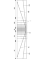
図3は、液晶素子において、配光パターンを可変に制御するためにそれぞれ個別に透過率を制御して光照射範囲と減光範囲(ないし非照射範囲)を形成することができる複数の画素領域を説明するための図である。図示のように、配光パターンを形成するための各画素領域は、図中左右方向において中央に配置された第1ブロック50と、第1ブロック50の左右両側にそれぞれ配置された第2ブロック51R、51Lと、第2ブロック51R、51Lの左右両側にそれぞれ配置された第3ブロック52R、52Lを含む。
FIG. 3 shows, in a liquid crystal element, a plurality of pixel regions capable of forming a light irradiation range and a light reduction range (or non-irradiation range) by individually controlling the transmittance in order to variably control the light distribution pattern. It is a figure for explaining. As shown in the figure, each pixel region for forming a light distribution pattern consists of a
第1ブロック50は、図中左右方向に延びる境界60によって上下に区画された複数の画素領域を含んでいる。第2ブロック51Rは、境界60によって上下に区画された複数の画素領域と、図中右肩上がりに傾斜して延びる境界61R、62Rによってそれぞれ上下に区画された複数の画素領域を含んでいる。第3ブロック52Rは、境界61R、62Rによってそれぞれ上下に区画された複数の画素領域を含んでいる。同様に、第2ブロック51Lは、境界60によって上下に区画された複数の画素領域と、図中左肩上がりの斜め方向に延びる境界61L、62Lによってそれぞれ上下に区画された複数の画素領域を含んでいる。第3ブロック52Lは、境界61L、62Lによってそれぞれ上下に区画された複数の画素領域を含んでいる。
The
図4は、図3に示すa部の拡大図である。第1ブロック50には、中心線oを挟んで左右に4つずつ配置された長方形状の複数の画素領域70と、各画素領域70の図中下側にそれぞれ配置された略正方形状の複数の画素領域71が含まれている。各画素領域70は、それぞれ図中上下方向に長手方向を有する。各画素領域71は、それぞれ何れかの画素領域70の直下に配置されている。各画素領域71の幅(左右方向長さ)は、直上の画素領域70とほぼ同じであり、かつ幅方向の位置を揃えて配置されている。
FIG. 4 is an enlarged view of part a shown in FIG. In the
第2ブロック51Rには、それぞれ図中の最上段に配置された略台形状の画素領域80、81、82、83、84、85、86と、図中中段に配置された三角形状の画素領域87および略台形状の画素領域88、89、90、91、92、93と、図中最下段に配置された矩形状の画素領域94、95、96および略台形状の画素領域97、98、99、100が含まれている。各画素領域80、87、94は、それぞれの幅を同一にして幅方向位置を揃えて上下方向に配列されている。他の画素領域も同様にして配列されている。
In the
この第2ブロック51Rおよび図4では示していない第3ブロック52Rでは、右肩上がりに傾斜して延びる境界61R、62Rによって各画素領域80~100等が区画されているので、例えば、各画素領域80~86等を減光範囲に対応させて各画素領域87~100を光照射範囲に対応させることで、境界62Rに沿って明暗の境界線を有する配光パターンを得ることができる。同様に、各画素領域80~93等を減光範囲に対応させて各画素領域94~100等を光照射範囲に対応させることで、境界61Rに沿って明暗の境界線を有する配光パターンを得ることができる。すなわち、右肩上がりに傾斜して直線状に延びる明暗の境界線を有する配光パターンを得ることができる。
In the
また、第2ブロック51Lの各画素領域は、中心線oを挟んで第2ブロック51Rと対称に配置されている。同様に、図4では図示しない第3ブロック52Lの各画素領域は、中心線oを挟んで第3ブロック52Rと対称に配置されている。これら各画素領域において上記と同様に減光範囲と光照射範囲を対応付けることで、境界61Lに沿って明暗の境界線を有する配光パターンや境界62Lに沿って明暗の境界線を有する配光パターンを得ることができる。すなわち、左肩上がりに傾斜して直線状に延びる明暗の境界線を有する配光パターンを得ることができる。
Each pixel region of the
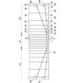
図5は、各画素領域に対応する液晶素子の画素電極の構造例を示す平面図である。ここでは、第1ブロック50の中心線oから右側の一部分と第2ブロック51Rの一部分に対応する画素電極が示されている。なお、第1ブロック50の左側と第2ブロック51Lの画素電極は、図示のものと中心線oを挟んで左右対称となるのでここでは図示を省略する。上記した図2に示した各画素電極34は、図示の各画素電極170~200の何れかに対応する。
FIG. 5 is a plan view showing a structural example of a pixel electrode of a liquid crystal element corresponding to each pixel region. Here, pixel electrodes corresponding to a portion on the right side of the center line o of the
各画素電極170は、上記の各画素領域70に対応した平面視形状を有する。各画素電極171は、上記の各画素領域71に対応した平面視形状を有する。各画素電極180~186は、それぞれ上記の各画素領域80~86に対応した平面視形状を有する。各画素電極187~193は、それぞれ上記の各画素領域87~93に対応した平面視形状を有する。各画素電極194~200は、それぞれ上記の各画素領域94~100に対応した平面視形状を有する。
Each
これら各画素電極180等は、上記のように下層側に設けられた各配線部36の何れかと接続されており、それぞれ個別に電圧を印加することができる。それにより、各画素電極180等と共通電極33との間に電界が発生し、その部分において液晶層37の液晶分子配向を制御することができる。それにより、光の透過率を各画素領域において個別に制御して種々の配光パターンを実現することができる。
Each of these
図6は、車両用灯具システムにおいて想定される道路状況の一例を説明するための図である。図示のように、例えば本実施形態では、自車両100の通行帯(通行区分)が左側通行に指定されており、かつ、道路の属性が市街地道路などの片側一車線の交互通行の道路である場合を想定する。そして、自車両100の左側の路側帯に存在する歩行者101Aや対向車線の右側の路側帯に存在する歩行者101Bに対してグレアを与えることなくこれらの歩行者101A、101Bの存在を自車両の運転者へ知らせるために効果的な配光パターンを形成するものとする。
FIG. 6 is a diagram for explaining an example of road conditions assumed in the vehicle lamp system. As shown in the figure, for example, in this embodiment, the lane (traffic division) of the
図7は、歩行者が存在する場合の配光パターンの一例を説明するための図である。図7では、運転席から自車両の前方道路を見た際の様子が模式的に示されている。ここでは、自車両の前方の所定位置において鉛直方向に立てられた仮想面上に形成される配光パターンを説明する。図示のように、本実施形態の車両用灯具システムでは、道路脇に歩行者が存在する場合には、図中上側に相対的に暗い領域である減光領域110が設定され、下側に相対的に明るい領域である光照射領域が設定された配光パターンが形成される。図中ではこの減光領域110を判別しやすいように模様を付して示している。
FIG. 7 is a diagram for explaining an example of a light distribution pattern when a pedestrian is present. FIG. 7 schematically shows a state when the road ahead of the vehicle is viewed from the driver's seat. Here, a light distribution pattern formed on a virtual plane erected in the vertical direction at a predetermined position in front of the own vehicle will be described. As shown in the figure, in the vehicle lighting system of the present embodiment, when there is a pedestrian on the side of the road, a
図示のように、減光領域110は、上下方向角度0°よりも上側に設けられており、左右方向角度0°付近から右肩上がりで傾斜して延びる明暗境界線111Rと、左右方向角度0°付近から左肩上がりで傾斜して延びる明暗境界線111Lとを有している。これら明暗境界線111R、111Lよりも下側は光照射領域に設定されている。図示の例では、左側通行を想定しているので、左側の明暗境界線111Lのほうが右側の明暗境界線111Rよりも図中左右方向を基準とした傾斜角度(傾斜度合い)を大きく設定されている。これは、見かけ上、左側の歩行者101Aのほうが自車両100への接近が早いためである。なお、通行区分が右側通行の場合には、明暗境界線111R、111Lの傾斜角度(傾斜度合い)が図示の例と反対に設定される。
As shown in the drawing, the
各明暗境界線111R、111Lの傾斜角度は、歩行者の位置(前後左右)、歩行者の頭部位置の高さ、自車両に対するランプユニット1の取付位置の高さを考慮し、かつ自車両へ近づくにつれて見かけ上は斜め上方向へ移動する歩行者の頭部位置よりも下側に各明暗境界線111R、111Lが配置されるように定められる。なお、各明暗境界線111R、111Lの傾斜角度は、上記した境界61R、62R、61L、62Lに対応して定まるものであり(図3、図4参照)、これら境界61R、62R、61L、62Lは、画素電極の形状に対応して定まるものである(図5参照)。
The inclination angles of the light-
各明暗境界線111R、111Lの傾き角度を設定する方法の一例について以下に説明する。ここで、自車両の前後方向に平行であって自車両の車幅方向の中央を通る軸を基準軸P(図6参照)として、歩行者の左右方向位置をX、自車両から歩行者までの距離をY、歩行者の頭部位置の高さ(ここでは首下の高さ)をZ、ランプユニット1の取付位置の高さをHとする。このとき、明暗境界線111Rまたは111Lの左右方向の形成範囲を基準軸からの角度θLRで表すものとすると、この角度θLRは以下のように求めることができる。
θLR=ATAN(X/Y) ・・・(1)
An example of a method for setting the inclination angles of the bright/
θ LR =ATAN(X/Y) (1)
(1)式において、歩行者の左右方向位置Xについては、例えば道路幅を片側3.5mと仮定すれば、自車両左側の歩行者については基準軸から-1.75m、右側の歩行者については基準軸から+5.75mという固定値を用いることができる。そして、歩行者までの距離Yは、制動停止距離として適した値(例えば40m~100)の範囲で指定すればよい。それにより、明暗境界線111Rまたは111Lの左右方向の形成範囲を基準軸からの角度θLRとして求めることができる。
In equation (1), the left-right position X of the pedestrian is -1.75 m from the reference axis for the pedestrian on the left side of the vehicle, and the right side pedestrian is can use a fixed value of +5.75 m from the reference axis. Then, the distance Y to the pedestrian may be specified within a range of values (for example, 40 m to 100) suitable for the braking stop distance. Thereby, the formation range of the light/
次に、明暗境界線111R、111Lの上下方向の形成範囲をランプユニット1の取付位置を基準とした上下方向の角度θUDで表すものとすると、この角度θUDは以下のように求めることができる。
θUD=ATAN((Z-H)/(X2+Y2)1/2) ・・・(2)
Next, assuming that the formation range of the light-
θ UD =ATAN((Z−H)/(X 2 +Y 2 ) 1/2 ) (2)
(2)式において、歩行者の頭部位置の高さZは、例えば固定値とする。このときのZの値は、例えば比較的背の低い人であっても対応できるように130cm程度とすることが好ましい。また、ランプユニット1の取付位置の高さHは既知の値である。そして、上記のように、歩行者までの距離Yは、制動停止距離として適した値(例えば40m~100)の範囲で指定すればよい。それにより、明暗境界線111Rまたは111Lの上下方向の形成範囲を基準軸からの角度θUDとして求めることができる。
In the expression (2), the height Z of the pedestrian's head position is, for example, a fixed value. The value of Z at this time is preferably about 130 cm so that even a relatively short person can handle it. Also, the height H of the mounting position of the
上記の(1)式、(2)式を用いることで、各明暗境界線111R、111Lが歩行者の頭部位置よりも下側となるようにそれらの傾き角度を適切に設定することができるので、歩行者へのグレアをより確実に防ぐことができる。
By using the above formulas (1) and (2), the inclination angles of the light/
各明暗境界線111R、111Lは境界61R、62Lと対応している。配光制御部22は、自車両100が左側通行帯を走行中と判断できる場合は境界61R、62Lを境として上方の画素領域(例えば画素領域84、91)を遮光制御し、下方の画素領域(例えば画素領域98)を透光制御することで明暗境界線を形成する。通行帯の判断は、運転者による手動での切り替え、GPSによる自車位置検出結果に基づく地図データの照会、撮像ユニット21による画像に基づく判断(白線検知等)などの方法によって行うことが可能である。通行帯が右側通行帯と判断されれば境界61L、62Rを境として同様の制御を行う。自車両が走行している通行帯を判断し、画素領域を区分する複数の境界から適切な組み合わせを選択することで明暗境界線の傾き角度を状況に応じて適切に変更させることもできる。
Bright and
図8は、車両用灯具システムの動作を説明するためのフローチャートである。なお、情報処理の結果に矛盾や不整合を生じない限りにおいて、処理の順序を入れ替えることや、他の処理を追加することも可能である。 FIG. 8 is a flowchart for explaining the operation of the vehicle lamp system. It should be noted that it is possible to change the order of processing or add other processing as long as the result of information processing does not produce contradiction or inconsistency.
車両のライトスイッチが操作されて前照灯の点灯が指示されると、図示しないロービーム用灯具によりロービームが照射される(ステップS11)。また、配光制御部22は、撮像ユニット21により検出される前方車両の位置に応じて、ハイビームの照射範囲のうち、前方車両の存在する一定範囲を減光範囲として、それ以外の範囲を光照射範囲に設定する点灯制御であるADB(Adaptive Driving Beam)制御を実行する(ステップS12)。
When the light switch of the vehicle is operated to instruct the lighting of the headlamp, a low beam is emitted by a low beam lamp (not shown) (step S11). In addition, the light
次に、配光制御部22は、GPSセンサ25により検出される自車両の現在位置と地図DB24に格納された地図データを用いて、自車両が現在走行している道路の属性が市街地に対応するものであるか否かを判定する(ステップS13)。例えば、現在走行している道路の種別が県道や市道である場合あるいは車線数が片道一車線である場合には、配光制御部22は、現在の道路の属性が市街地に対応するものであると判定する。現在の道路の属性が市街地に対応するものではない場合には(ステップS13;NO)、ステップS12に戻り、ADB制御が継続される。なお、ステップS13では地図データのほか、撮像ユニット21による画像認識処理により街灯の数に基づいて市街地に係る判定を行うこともできる。この場合、例えば所定の数以上に街灯が存在する場合には市街地と判定できる。
Next, the light
現在の道路の属性が市街地に対応するものである場合に(ステップS13;YES)、配光制御部22は、撮像ユニット21の検出結果に基づいて、歩行者が存在するか否かを判定する(ステップS14)。歩行者が存在しない場合には(ステップS14;NO)、ステップS12に戻り、ADB制御が継続される。
If the current road attribute corresponds to an urban area (step S13; YES), the light
歩行者が存在する場合には(ステップS14;YES)、配光制御部22は、歩行者に対応する減光領域を設定する制御を行う(ステップS15)。具体的には、上記した図7に例示したような減光領域110を含んだ配光パターンが形成され、自車両の前方に照射される。その後、ステップS12へ戻る。
If a pedestrian exists (step S14; YES), the light
以上のような実施形態によれば、構成の複雑化並びにコスト増を招くことなく、歩行者への追従性の高い配光パターンを実現し得る。 According to the above-described embodiments, a light distribution pattern that is highly followable to pedestrians can be realized without complicating the configuration and increasing costs.
なお、本発明は上記した実施形態の内容に限定されるものではなく、本発明の要旨の範囲内において種々に変形して実施をすることが可能である。例えば、上記した実施形態では画像認識処理によって歩行者の有無を検出していたが他の手段、例えばLIDAR(Light Detection and Ranging)などの光センサやレーダーなどの電波センサを用いて歩行者の有無を検出してもよい。 It should be noted that the present invention is not limited to the contents of the above-described embodiments, and various modifications can be made within the scope of the gist of the present invention. For example, in the above-described embodiment, the presence or absence of pedestrians is detected by image recognition processing. may be detected.
また、上記の実施形態では減光領域110の全体が減光するように制御する例を説明していたがこれに限られない。減光領域110のうち、さらに歩行者と重なる画素領域のみを減光するようにしてもよい。例えば境界61Rより上方の画素領域であっても歩行者と重なる画素領域83、90は減光させるが、歩行者とは重ならない画素領域82、84、89、91は通常通りに光照射するようにしてもよい。この場合、自車両と歩行者の相対的な位置の変化に応じて減光させる画素領域を切り替えていくこともできる。例えば、見た目上の歩行者位置の変化に合わせて減光させる画素領域を画素領域83、90から画素領域84、91に切り替えることができる。見た目上の歩行者位置の変化は撮像ユニット21による画像認識処理により判断することや、自車両の速度および加速度から予測することで判断することができる。このように減光する画素領域を切り替えることにより、歩行者にグレアを与えてしまうことを回避しつつ、光照射される領域を広く残すことで運転者にとって周囲を視認しやすくすることができる。
Also, in the above-described embodiment, an example of performing control so that the
また、上記の実施形態ではハイビームの照射範囲をADB制御していることを想定しているが、ロービームのみの使用時において歩行者の存在を運転者に知らせるために使用することもできる。例えば境界61Rより下方の画素領域であっても歩行者と重なる画素領域97のみを光照射するように制御し、他の画素領域は遮光制御する。このようにすることでロービーム配光に加え、歩行者位置に照射が行われるため運転者にとって歩行者の存在を認識しやすくすることができる。この場合、自車両と歩行者の相対的な位置の変化に応じて光照射させる画素領域を切り替えていくこともできる。例えば、見た目上の歩行者位置の変化に合わせ光照射させる画素領域を画素領域97から画素領域98に切り替えることができる。見た目上の歩行者位置の変化は撮像ユニット21による画像認識処理から判断することや、自車両の速度および加速度から予測することで判断することができる。
In the above embodiment, it is assumed that the high beam irradiation range is ADB controlled, but it can also be used to inform the driver of the presence of pedestrians when only the low beam is used. For example, even in the pixel area below the
また、上記の実施形態では明暗境界線及び境界を直線状としたが、中央から離れるほど鉛直方向の高さが高くなるように滑らかに傾斜した形状であればよく、曲線ないし、曲線と直線を組み合わせた形状であってもよい。 In the above-described embodiment, the light-dark boundaries and boundaries are straight lines, but they may be smoothly inclined so that the height in the vertical direction increases with increasing distance from the center. It may be a combined shape.
また、上記した実施形態においては、液晶素子として画素電極と配線部が二層に積層された構成を例示していたが液晶素子の構成はこれに限定されない。同一面上において各画素電極の相互間や周囲に配線部を設けるようにして液晶素子を構成してもよい。また、液晶素子の動作モードについても、入射光の透過率を電気的に制御し得る限り、垂直配向型に限定されない。また、画素電極の形状も上記した実施形態のものに限定されず、明暗境界線を形成可能な限りにおいて適宜設定することができる。 In addition, in the above-described embodiments, the structure in which the pixel electrodes and the wiring portions are laminated in two layers was exemplified as the liquid crystal element, but the structure of the liquid crystal element is not limited to this. The liquid crystal element may be configured by providing wiring portions between and around the pixel electrodes on the same plane. Also, the operation mode of the liquid crystal element is not limited to the vertical alignment type as long as the transmittance of incident light can be electrically controlled. Also, the shape of the pixel electrode is not limited to that of the above-described embodiment, and can be appropriately set as long as a bright-dark boundary line can be formed.
11:光源、12:リフレクタ、13:液晶素子、14a、14b:偏光板、15:投影レンズ、21:撮像ユニット、22:配光制御部、23:液晶駆動部、24:地図データベース(DB)、25:GPSセンサ、60、61L、61R、62L、62R:境界、70~91:領域、170~200:画素電極、100:自車両、101A、101B:歩行者、110:減光領域、111L、111R:明暗境界線 11: light source, 12: reflector, 13: liquid crystal element, 14a, 14b: polarizing plate, 15: projection lens, 21: imaging unit, 22: light distribution control section, 23: liquid crystal driving section, 24: map database (DB) , 25: GPS sensor, 60, 61L, 61R, 62L, 62R: boundary, 70 to 91: area, 170 to 200: pixel electrode, 100: own vehicle, 101A, 101B: pedestrian, 110: dimming area, 111L , 111R: light-dark border
Claims (6)
選択的な光照射を実行可能なランプユニットと、
前記ランプユニットの動作を制御する制御装置と、
を含み、
前記制御装置は、前記自車両の前方に歩行者が存在する場合に、前記自車両の車幅方向の中央を基準にした左前方及び右前方の双方に対して、当該中央から離れるほど鉛直方向の高さが高くなるように傾斜した明暗境界線を含む配光パターンであって当該明暗境界線の上側領域が相対的に暗く下側領域が相対的に明るい配光パターンを前記ランプユニットに形成させるものであり、
前記ランプユニットは、前記配光パターンにおける前記明暗境界線として、前記自車両の左前方において当該自車両側から見て左上がりに傾斜する第1明暗境界線と、前記自車両の右前方において当該自車両側から見て右上がりに形成される第2明暗境界線とを形成可能に構成されているとともに、前記第1明暗境界線と前記第2明暗境界線のそれぞれの傾斜角度を切り替え可能に構成されており、
前記制御装置は、前記第1明暗境界線と前記第2明暗境界線のうち前記自車両の通行帯として設定されている側に配置されるものの前記傾斜角度が相対的に大きくなるように前記ランプユニットを制御して前記配光パターンを形成させる、
車両用灯具システム。 A vehicle lamp system for irradiating light forward of a vehicle,
a lamp unit capable of performing selective light irradiation;
a control device for controlling the operation of the lamp unit;
including
When there is a pedestrian in front of the vehicle, the control device moves vertically toward both the left front and the right front with respect to the center of the vehicle in the vehicle width direction as the distance from the center increases. A light distribution pattern including a light-dark boundary line inclined so that the height of the light-dark boundary line is relatively dark and the lower region is relatively bright. and
The lamp unit includes, as the light-dark boundary lines in the light distribution pattern, a first light-dark boundary line that slopes upward to the left when viewed from the vehicle side on the left front of the vehicle, and a first light-dark boundary line on the right front of the vehicle. A second bright/dark boundary line formed upward to the right when viewed from the vehicle side can be formed, and the inclination angles of the first bright/dark boundary line and the second bright/dark boundary line can be switched. is composed of
The controller controls the ramp so that the tilt angle of the first bright-dark boundary line and the second bright-dark boundary line, which is located on the side set as the traffic zone for the own vehicle, is relatively large. controlling a unit to form the light distribution pattern;
Vehicle lighting system.
請求項1に記載の車両用灯具システム。 The control device is based on either manual switching by the driver, reference to map data based on the results of vehicle position detection by GPS, or image recognition processing using an image taken in front of the vehicle. determine the traffic lane of the vehicle,
The vehicle lamp system according to claim 1.
前記歩行者の有無の判断並びに前記通行帯の判断は、前記撮像ユニットによる検出結果に基づいて前記制御装置により実行される、
請求項1又は2に記載の車両用灯具システム。 further comprising an imaging unit that captures an area in front of the own vehicle, generates an image, and performs image recognition processing on the image;
Determination of the presence or absence of the pedestrian and determination of the traffic lane are performed by the control device based on the detection result of the imaging unit.
The vehicle lamp system according to claim 1 or 2.
前記液晶素子は、前記光の透過率を個別に制御可能な複数の画素領域を有しており、当該複数の画素領域のうちの少なくとも一部同士を相互に分離する複数の境界が前記明暗境界線に対応した直線状に設けられている、
請求項1~3の何れか1項に記載の車両用灯具システム。 The lamp unit includes a light source and a liquid crystal element that forms an image corresponding to the light distribution pattern using light incident from the light source,
The liquid crystal element has a plurality of pixel regions whose light transmittance can be individually controlled, and a plurality of boundaries separating at least some of the plurality of pixel regions from each other are defined as the light-dark boundaries. It is provided in a straight line corresponding to the line,
The vehicle lamp system according to any one of claims 1 to 3.
請求項1~4の何れか1項に記載の車両用灯具システム。 The control device causes the lamp unit to form the light distribution pattern when the attribute of the road at the current position of the vehicle corresponds to an urban area and a pedestrian exists in front of the vehicle.
The vehicle lamp system according to any one of claims 1 to 4.
前記制御装置が、前記自車両の前方に歩行者が存在する場合に、前記自車両の車幅方向の中央を基準にした左前方及び右前方の双方に対して、当該中央から離れるほど鉛直方向の高さが高くなるように傾斜した明暗境界線を含む配光パターンであって当該明暗境界線の上側領域が相対的に暗く下側領域が相対的に明るい配光パターンを前記ランプユニットに形成させるものであって、
前記ランプユニットは、前記配光パターンにおける前記明暗境界線として、前記自車両の左前方において当該自車両側から見て左上がりに傾斜する第1明暗境界線と、前記自車両の右前方において当該自車両側から見て右上がりに形成される第2明暗境界線とを形成可能に構成されているとともに、前記第1明暗境界線と前記第2明暗境界線のそれぞれの傾斜角度を切り替え可能に構成されており、
前記制御装置は、前記第1明暗境界線と前記第2明暗境界線のうち前記自車両の通行帯として設定されている側に配置されるものの前記傾斜角度が相対的に大きくなるように前記ランプユニットを制御して前記配光パターンを形成させる、
車両用灯具システムの制御方法。
A control method in a vehicle lighting system that includes a lamp unit capable of selectively emitting light and a control device that controls the operation of the lamp unit, and that emits light forward of the vehicle, comprising:
When there is a pedestrian in front of the vehicle, the control device controls both the left front and the right front with respect to the center of the vehicle in the vehicle width direction in the vertical direction as the distance from the center increases. A light distribution pattern including a light-dark boundary line inclined so that the height of the light-dark boundary line is relatively dark and the lower region is relatively bright. and
The lamp unit includes, as the light-dark boundary lines in the light distribution pattern, a first light-dark boundary line that slopes upward to the left when viewed from the vehicle side on the left front of the vehicle, and a first light-dark boundary line on the right front of the vehicle. A second bright/dark boundary line formed upward to the right when viewed from the vehicle side can be formed, and the inclination angles of the first bright/dark boundary line and the second bright/dark boundary line can be switched. is composed of
The controller controls the ramp so that the tilt angle of the first bright-dark boundary line and the second bright-dark boundary line, which is located on the side set as the traffic zone for the own vehicle, is relatively large. controlling a unit to form the light distribution pattern;
A control method for a vehicle lighting system.
Priority Applications (1)
| Application Number | Priority Date | Filing Date | Title |
|---|---|---|---|
| JP2018244927A JP7219085B2 (en) | 2018-12-27 | 2018-12-27 | Lamp units, vehicle lighting systems |
Applications Claiming Priority (1)
| Application Number | Priority Date | Filing Date | Title |
|---|---|---|---|
| JP2018244927A JP7219085B2 (en) | 2018-12-27 | 2018-12-27 | Lamp units, vehicle lighting systems |
Publications (2)
| Publication Number | Publication Date |
|---|---|
| JP2020104679A JP2020104679A (en) | 2020-07-09 |
| JP7219085B2 true JP7219085B2 (en) | 2023-02-07 |
Family
ID=71447967
Family Applications (1)
| Application Number | Title | Priority Date | Filing Date |
|---|---|---|---|
| JP2018244927A Active JP7219085B2 (en) | 2018-12-27 | 2018-12-27 | Lamp units, vehicle lighting systems |
Country Status (1)
| Country | Link |
|---|---|
| JP (1) | JP7219085B2 (en) |
Families Citing this family (2)
| Publication number | Priority date | Publication date | Assignee | Title |
|---|---|---|---|---|
| JP7470592B2 (en) * | 2020-07-21 | 2024-04-18 | スタンレー電気株式会社 | Liquid crystal elements, vehicle headlights |
| JP2022167222A (en) * | 2021-04-22 | 2022-11-04 | スタンレー電気株式会社 | Liquid crystal element, lighting figure for vehicles, and lighting fixture system for vehicles |
Citations (1)
| Publication number | Priority date | Publication date | Assignee | Title |
|---|---|---|---|---|
| JP2005183327A (en) | 2003-12-24 | 2005-07-07 | Stanley Electric Co Ltd | Vehicle headlamp |
Family Cites Families (1)
| Publication number | Priority date | Publication date | Assignee | Title |
|---|---|---|---|---|
| CN105593062B (en) * | 2013-09-26 | 2018-05-11 | 株式会社小糸制作所 | Lamps apparatus for vehicle control system |
-
2018
- 2018-12-27 JP JP2018244927A patent/JP7219085B2/en active Active
Patent Citations (1)
| Publication number | Priority date | Publication date | Assignee | Title |
|---|---|---|---|---|
| JP2005183327A (en) | 2003-12-24 | 2005-07-07 | Stanley Electric Co Ltd | Vehicle headlamp |
Also Published As
| Publication number | Publication date |
|---|---|
| JP2020104679A (en) | 2020-07-09 |
Similar Documents
| Publication | Publication Date | Title |
|---|---|---|
| CN102897083B (en) | The light distribution control of head light | |
| US10830407B2 (en) | Vehicular lamp | |
| JP7545521B2 (en) | Vehicle headlights | |
| US10981493B2 (en) | Control apparatus for vehicle headlight, control method for vehicle headlight, vehicle headlight system | |
| JP6959852B2 (en) | Lighting device | |
| WO2022153754A1 (en) | Headlight control device, headlight control method, and headlight system | |
| JP2019121520A (en) | Headlight device | |
| US10551018B2 (en) | Vehicular lamp, vehicular lamp system | |
| JP2020055516A (en) | Vehicle headlights | |
| CN115899609A (en) | Adaptive light source with spatial light modulator | |
| JP7219085B2 (en) | Lamp units, vehicle lighting systems | |
| JP6861044B2 (en) | Vehicle lighting control method and vehicle lighting control device | |
| EP3495717A1 (en) | Vehicular lamp system | |
| WO2024004498A1 (en) | Vehicle lighting system | |
| JP2019169340A (en) | Lighting device, and light projection system | |
| JP2015016733A (en) | Lighting control system | |
| US11097651B2 (en) | Vehicle headlight beam control having a liquid crystal driving circuit and liquid crystal broadening device | |
| CN120500422A (en) | Vehicle lamp system, control device, light distribution control method, and non-transitory computer-readable medium | |
| JP7281269B6 (en) | Vehicle lighting units and vehicles | |
| WO2022196296A1 (en) | Vehicle lamp control device, vehicle lamp control method and vehicle lamp system | |
| JP2022020973A (en) | Illumination device | |
| JP7481921B2 (en) | Vehicle headlights | |
| JP2019140031A (en) | Lighting appliance system for vehicle | |
| JP2022002933A (en) | Headlamp for vehicle | |
| JP2022002932A (en) | Vehicle headlights |
Legal Events
| Date | Code | Title | Description |
|---|---|---|---|
| A621 | Written request for application examination |
Free format text: JAPANESE INTERMEDIATE CODE: A621 Effective date: 20211101 |
|
| A131 | Notification of reasons for refusal |
Free format text: JAPANESE INTERMEDIATE CODE: A131 Effective date: 20220830 |
|
| A977 | Report on retrieval |
Free format text: JAPANESE INTERMEDIATE CODE: A971007 Effective date: 20220831 |
|
| A601 | Written request for extension of time |
Free format text: JAPANESE INTERMEDIATE CODE: A601 Effective date: 20221020 |
|
| A521 | Request for written amendment filed |
Free format text: JAPANESE INTERMEDIATE CODE: A523 Effective date: 20221111 |
|
| TRDD | Decision of grant or rejection written | ||
| A01 | Written decision to grant a patent or to grant a registration (utility model) |
Free format text: JAPANESE INTERMEDIATE CODE: A01 Effective date: 20230106 |
|
| A61 | First payment of annual fees (during grant procedure) |
Free format text: JAPANESE INTERMEDIATE CODE: A61 Effective date: 20230126 |
|
| R150 | Certificate of patent or registration of utility model |
Ref document number: 7219085 Country of ref document: JP Free format text: JAPANESE INTERMEDIATE CODE: R150 |
|
| R250 | Receipt of annual fees |
Free format text: JAPANESE INTERMEDIATE CODE: R250 |