JP7242515B2 - Microbial inspection method for packaged beverages - Google Patents
Microbial inspection method for packaged beverages Download PDFInfo
- Publication number
- JP7242515B2 JP7242515B2 JP2019223730A JP2019223730A JP7242515B2 JP 7242515 B2 JP7242515 B2 JP 7242515B2 JP 2019223730 A JP2019223730 A JP 2019223730A JP 2019223730 A JP2019223730 A JP 2019223730A JP 7242515 B2 JP7242515 B2 JP 7242515B2
- Authority
- JP
- Japan
- Prior art keywords
- container
- forming tool
- spout forming
- spout
- beverage
- Prior art date
- Legal status (The legal status is an assumption and is not a legal conclusion. Google has not performed a legal analysis and makes no representation as to the accuracy of the status listed.)
- Active
Links
Images


Landscapes
- Measuring Or Testing Involving Enzymes Or Micro-Organisms (AREA)
Description
容器入り飲料の微生物検査方法に関する。 The present invention relates to a microbial inspection method for packaged beverages.
特許文献1には、ボトル容器から飲料を分注機に取り付けたノズルで吸引して培地に注入して、各培地(シャーレ)に順次供給することを自動化した技術が開示されている。
しかし、特許文献1の技術では、容器の外面に付着した菌が、培地に混入するおそれがあった。
また、微生物検査方法では、容器が瓶や缶等の樹脂製容器でない場合には、容器から飲料を採取し難いという問題があった。
However, with the technique of
Further, in the microbial inspection method, when the container is not a resin container such as a bottle or a can, there is a problem that it is difficult to collect the beverage from the container.
そこで、本発明の目的は、外部からの菌の混入を防止できると共に容器の種類にかかわらず、飲料を容易に採取できる容器入り飲料の微生物検査方法を提供することである。 SUMMARY OF THE INVENTION Accordingly, an object of the present invention is to provide a microbial examination method for a packaged beverage that can prevent contamination with bacteria from the outside and easily collect the beverage regardless of the type of the container.
請求項1に記載の発明は、容器入り飲料の容器の外面を薬液で殺菌する容器殺菌工程と、前記容器入り飲料の前記容器の外面に無菌処理された熱風を吹き付ける熱風吹き付け工程と、前記容器に注ぎ口を形成する注ぎ口形成工程と、前記容器に形成した注ぎ口から飲料を採取する飲料採取工程と、前記採取した飲料から微生物を培養する培養工程と、を備える容器入り飲料の微生物検査方法において、前記容器は缶であり、前記注ぎ口形成工程は、缶の底を上に向けて缶の底に注ぎ口形成具で注ぎ口を形成しており、前記注ぎ口形成具は缶切り又は加熱した熱材であり、缶の底に上から缶切り又は熱材を差し入れて穿孔しており、前記注ぎ口形成工程で使用した前記注ぎ口形成具を殺菌する注ぎ口形成具殺菌工程を、更に備えることを特徴とする容器入り飲料の微生物検査方法である。
The invention according to
請求項2に記載の発明は、請求項1に記載の発明において、前記注ぎ口形成具殺菌工程は、注ぎ口形成具を注ぎ口形成具用薬液水槽に浸漬して殺菌し、次に前記注ぎ口形成具用薬液水槽から取り出して乾燥した後に、他の容器の前記注ぎ口形成工程で使用することを特徴とする。
The invention according to claim 2 is based on the invention according to
請求項3に記載の発明は、請求項2に記載の発明において、前記容器殺菌工程は容器用薬液水槽に容器を浸漬して殺菌しており、前記注ぎ口形成具用薬液水槽内の薬液を前記容器用薬液水槽に流入していることを特徴とする。 The invention according to claim 3 is based on the invention according to claim 2, wherein the container sterilization step sterilizes the container by immersing it in a container chemical water tank, and the chemical liquid in the spout forming tool chemical water tank is sterilized. It is characterized by flowing into the container chemical liquid tank.
請求項4に記載の発明は、請求項1~3のいずれか一項に記載の発明において、少なくとも前記注ぎ口形成工程及び前記飲料採取工程は、ロボットアームを備えるクリーンルーム内で実行しており、前記ロボットアームが、前記容器又は前記注ぎ口形成具を把持して、前記容器を穿孔することを特徴とする。
The invention according to claim 4 is the invention according to any one of
請求項5に記載の発明は、請求項4に記載の発明において、前記注ぎ口形成具殺菌工程は、前記クリーンルーム内で実行しており、前記ロボットアームが前記注ぎ口形成具を搬送コンベアに取り付けた後、搬送コンベアにより注ぎ口形成具用薬液水槽に浸漬し及び浸漬後取り出すことを特徴とする。
The invention according to
請求項6に記載の発明は、請求項5に記載の発明において、前記注ぎ口形成具殺菌工程は、前記注ぎ口形成具を前記注ぎ口形成具用薬液水槽に浸漬して取り出した後に、熱風を吹き付けて乾燥・滅菌することを特徴とする。
The invention according to
請求項1に記載の発明によれば、検査対象の飲料を容器から採取する前に、飲料入りボトルの外面を殺菌するので、外部からの菌が培地に混入するのを防止できる。
また、容器内の飲料を採取する際には、注ぎ口形成具により容器を穿孔することで、注ぎ口を形成して容易に飲料の採取ができる。
使用した注ぎ口形成具は、殺菌することで再使用できる。
缶の底に注ぎ口を形成しているので、プルトップ式の缶でもプルタブが邪魔にならないから、注ぎ口を形成しやすい。
According to the first aspect of the invention, since the outer surface of the beverage bottle is sterilized before the beverage to be inspected is sampled from the container, bacteria from the outside can be prevented from entering the culture medium.
In addition, when the beverage in the container is to be collected, the container is pierced by the spout forming tool to form a spout so that the beverage can be easily collected.
Used spout formers can be reused after being sterilized.
Since the spout is formed at the bottom of the can, the pull tab does not get in the way even with a pull-top can, making it easy to form the spout.
請求項2に記載の発明によれば、請求項1に記載の発明と同様の作用効果を奏すると共に、注ぎ口形成工程で、注ぎ口形成具に飲料が付着した場合に薬液水槽で殺菌し、乾燥することで、付着した飲料の除去が容易にできる。
According to the invention of claim 2, the same effect as that of the invention of
請求項3に記載の発明によれば、請求項2に記載の発明と同様の作用効果を奏すると共に、薬液を効率的に使用できる。 According to the third aspect of the invention, the same effect as the second aspect of the invention can be obtained, and the chemical solution can be used efficiently.
請求項4に記載の発明によれば、請求項1~3のいずれか一項に記載の発明と同様の作用効果を奏すると共に、クリーンルーム内でロボットアームにより注ぎ口形成及び飲料採取を連続した自動化ができる。
According to the invention of claim 4 , the same effects as those of the invention of any one of
請求項5に記載の発明によれば、請求項4に記載の発明と同様の作用効果を奏すると共に、注ぎ口形成具に付着した飲料の除去と殺菌を自動で且つ効率的にできる。 According to the fifth aspect of the invention, the same effect as the fourth aspect of the invention can be obtained, and removal and sterilization of the beverage adhering to the spout forming tool can be automatically and efficiently performed.
請求項6に記載の発明によれば、請求項5に記載の発明と同様の作用効果を奏すると共に、注ぎ口形成具を殺菌後に乾燥、滅菌することで、自然乾燥する場合に比較して、次の使用までの時間を短縮できる。 According to the sixth aspect of the invention, the same effects as those of the fifth aspect of the invention can be obtained. You can shorten the time until the next use.
以下に、添付図面を参照して本発明の第1実施の形態について説明する。
第1実施の形態にかかる容器入り飲料の微生物検査方法は、メンブレンフィルター(MF)法による検査方法である。
図2に示すように、微生物検査施設1は、容器殺菌ブース3と、クリーンルーム(検査ブース)5と前室7とに分離してあり、容器殺菌ブース3、クリーンルーム5及び前室7で処理したのち、シャーレ取出工程S7-3及び培養工程S8で、容器内の飲料をシャーレに入れた培地で培養した後、コロニーの有無を検査する。本実施の形態では、一般細菌(水生菌を含む)、真菌(カビ、酵母)を検査する。
図3に示すように、検査対象となる容器入り飲料は缶入り飲料であり、容器9は天面にプルタブ9aを有するプルトップ式の缶である。また、検査対象となる容器入り飲料は製造ラインからサンプリングした製造後の缶入り飲料であり、飲料の種類は特に限定されないが、例えば、コーヒー系飲料や果樹系飲料である。
図2に示すように、この微生物検査施設1には、ロボットアーム11が設けられており、所定の工程をこのロボットアームで実施している。
A first embodiment of the present invention will be described below with reference to the accompanying drawings.
A microbial inspection method for container-packed beverages according to the first embodiment is an inspection method using a membrane filter (MF) method.
As shown in FIG. 2, the
As shown in FIG. 3, the packaged beverage to be inspected is a canned beverage, and the
As shown in FIG. 2, this
ここで、本実施の形態で使用するロボットアーム11について説明する。図10に示すように、ロボットアーム11は、多数の関節を有し、支柱11a、腕11b、ヘッド11cがそれぞれX方向回転、Y方向回転、Z方向の揺動等が自在な構成としてある。また、ヘッド11cには、係止具35等の治具が出し入れ自在に設けてあると共に把持部12により容器9等の物品を把持可能な構成としてある。
ロボットアーム11の姿勢、動き、把持部12や係止具35等の駆動や制御は、予めプログラムしたマイクロコンピュータにより制御されている。
Here, the
The posture and movement of the
以下に、図1及び図2を参照しつつ各検査工程を順次説明する。
図2に示すように、準備段階では、前室7で培地6を含むシャーレ8(図9参照)を準備しT1、無菌水準備T2、メンブレン準備T3、ファンネル(ろ過器)準備T4をしておく。これらの準備T1~T4は人手で行う。
Each inspection process will be sequentially described below with reference to FIGS. 1 and 2. FIG.
As shown in FIG. 2, in the preparation stage, a petri dish 8 (see FIG. 9) containing a
(1)容器殺菌工程S1
容器殺菌工程S1では、容器入り飲料の容器9の外面を薬液で殺菌する。検査対象となる容器9は工場で製造後のものをサンプリングして予め並べて配置してあり、ロボットアーム11(図10参照)が所定の容器9を把持して容器9を移動して、籠15(図3参照)に立設した状態で入れ、籠15を図3に示すように、容器用薬液水槽13に浸漬する。容器用薬液水槽13は、殺菌薬液を満たした水槽である。薬液水槽内13では、容器9は全体を殺菌水槽13内に水没している。薬液の薬剤は、過酸化水素や次亜塩素酸等である。
薬液水槽13では、水槽13内を撹拌し又は水流により、矢印Eで示すように薬液を流動させている。更に、籠15は、矢印Fで示すように、薬液水槽13内で上下に間欠動作させている。籠15の上下動作は、ロボットアーム11が籠15を把持して行う。
容器殺菌工程S1の薬液殺菌後に、ロボットアーム11は籠15を薬液水槽13から引き上げた後、籠15内の容器9をつかみ、容器9を熱風吹き付け工程S2のテーブルに立設する。
(1) Container sterilization step S1
In the container sterilization step S1, the outer surface of the
In the
After chemical sterilization in the container sterilization step S1, the
(2)熱風吹き付け工程S2
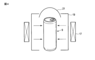
図4に示すように、熱風吹き付け工程S2では、テーブルに立設した容器9の側面からヒータ17で加熱した無菌風を送風機19から吹き付ける。熱風の温度は50℃~70℃であり、好ましくは65℃~70℃である。65℃~70℃であれば、効率よく滅菌や水滴除去ができる。また、容器9にはフード21を被せて、吹き付けた熱風が容器9の全体にあたって滞留し易くしている。
(2) Hot air blowing step S2
As shown in FIG. 4, in the hot air blowing step S2, sterile air heated by a
(3)注ぎ口形成工程S3
注ぎ口形成工程では、容器9内の飲料を注ぎ出す為の孔を容器9にあける。
本実施の形態では、図5に示すように、熱風吹き付け後のテーブルに載置した容器9を逆さに反転し、容器9の底面9bを上にして底面9bの上から加熱した熱材(注ぎ口形成具)23を差し仕込んで穿孔する。容器9の反転は、ロボットアーム11が容器9を把持して行う。熱材23は本実施の形態では棒材である。熱材23は常設の穿孔装置41で行う。穿孔装置41はシリンダー及びピストンの駆動機構で熱材23を上下動し、例えば熱材23は内蔵された電熱線で加熱している。
容器9の底面9bは熱材23により溶融して穿孔される。尚、容器9の底面9bを穿孔するときには、ロボットアーム11で容器9を保持している。一般に、缶飲料は空寸が小さい為、穿孔の際に熱材23に容器9内の飲料が接触して、飲料がこげて付着することがある。したがって、穿孔後の熱材23は洗浄及び殺菌する必要があるので、熱材23の洗浄及び殺菌(注ぎ口形成具殺菌工程S3-1及び乾燥・滅菌工程S3-2)については、後述する。
(3) Spout forming step S3
In the spout forming step, the
In the present embodiment, as shown in FIG. 5, the
The
(4)メンブレン設置工程S4
一方、図2に示すように、ロボットアーム11は、マニホールド25(図7参照)へファンネル27(図7参照)設置S4-1をした後、準備したメンブレン29(図8参照)を取り出しS4-2、ファンネル27にメンブレン29(図7参照)を設置するS4-3。設置したメンブレン29には、チューブ(図示せず)から無菌水を注入する(S4-4)。
(4) Membrane installation step S4
On the other hand, as shown in FIG. 2, the
(5)メンブレンろ過(飲料採取)工程S5
図7に示すように、ロボットアーム11は、容器9を把持して注ぎ口9c(図5参照)を形成した底面9bが下に向くように傾斜させてファンネル27に容器9内の飲料を注ぎ、ろ過する。
(5) Membrane filtration (beverage extraction) step S5
As shown in FIG. 7, the
(6)メンブレン切断工程S6
図8に示すように、ろ過後、ロボットアーム11により、ファンネル27の周壁27aを基台27bから外し、ロボットアーム11が保持する切断刃31でメンブレン29を2枚の半月状のメンブレン片29a、29bに切断する。
ファンネル27の基台27bには、その縁部27cに切断刃31の挿入溝33が形成されている。本実施の形態では、挿入溝33は縁部27cの対向する位置に2箇所形成されている。挿入溝33により、切断刃31でメンブレン29を引き切るときに切断刃31が縁部27cと干渉することなく、縁部27cを越えて引き操作できる。
(6) Membrane cutting step S6
As shown in FIG. 8, after filtration, the
The base 27b of the
(7)培地に貼付工程S7
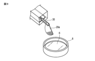
図9に示すように、ロボットアーム11は、ファンネル27の基台27bに載置されている一方のメンブレン片29aを係止具35で把持してメンブレン片29aを採取し(図2のS6-2)、シャーレ8の培地6に貼付する。係止具35は、例えばピンセットである。尚、メンブレン片29aをシャーレ8の培地6に添付する前に、シャーレ8の蓋を開けておく(図2のS7-1)。
その後、シャーレ8に蓋を被せる(図2のS7-2)。シャーレ8の蓋の開閉は、テーブル上に設けた自動機構により蓋を開閉するが、ロボットアーム11が行っても良い。
同様に、他方のメンブレン片29bも係止具35で把持し、他の種類の培地を入れたシャーレ8に貼付し、その後シャーレ8に蓋を被せる(図2のS7-2)。
(7) Attaching step S7 to medium
As shown in FIG. 9, the
Thereafter, the petri dish 8 is covered with a lid (S7-2 in FIG. 2). The opening and closing of the lid of the petri dish 8 is performed by an automatic mechanism provided on the table, but the
Similarly, the
(8)培養工程S8
蓋を被せた各シャーレ8は、そのまま取り出してS7-3培養器で培養する。培養後、コロニーの有無を観察する。
(8) Culture step S8
Each petri dish 8 covered with a lid is taken out as it is and cultured in an S7-3 incubator. After culturing, the presence or absence of colonies is observed.
(9)注ぎ口形成具殺菌工程S3-1
一方、注ぎ口形成工程S3で使用した熱材(注ぎ口形成具)23は、注ぎ口形成具殺菌工程で殺菌し、次に乾燥・滅菌工程S3-2で乾燥滅菌する。
図6(a)に示すように、注ぎ口形成具殺菌工程S3-1では、注ぎ口形成工程S3において、熱材23で容器9に注ぎ口を形成後、ロボットアーム11が熱材23を保持して、注ぎ口形成具用薬液水槽26に移動し、熱材23を浸漬して、殺菌及び洗浄し、次に乾燥・滅菌工程S3-2でロボットアーム11が熱材23を保持したまま、乾燥及び滅菌する。乾燥・滅菌は、図6(b)に示すように、電気滅菌器43で加熱して乾燥・滅菌する。電気滅菌器43としては、例えば、ループシネレータ(ヤマト科学株式会社製)を用いる。尚、熱材23を保持するロボットアーム11に代えて、上述の注ぎ口形成工程S3で用いた穿孔装置41が熱材23を保持して移動し、注ぎ口形成具殺菌工程S3-1及び乾燥・滅菌工程S3-2を実施しても良い。
(9) Spout forming tool sterilization step S3-1
On the other hand, the heating material (spout forming tool) 23 used in the spout forming step S3 is sterilized in the spout forming tool sterilization step, and then dried and sterilized in the drying/sterilizing step S3-2.
As shown in FIG. 6(a), in the spout forming tool sterilization step S3-1, after forming the spout in the
次に、本実施の形態の作用効果について説明する。
本実施の形態によれば、容器殺菌工程S1で容器9の外面を薬液で殺菌すると共に熱風吹き付け工程S2で無菌処理された熱風で外面を乾燥及び殺菌し、注ぎ口形成工程S3で穿孔した孔から容器内の飲料を採取し、メンブレン29でろ過するので、メンブレンフィルターろ過法(MF法)による微生物検査方法において、容器外面に付着した菌の混入を防止できる。
Next, the effects of this embodiment will be described.
According to this embodiment, the outer surface of the
容器殺菌工程S1では、図3に示すように、容器9を容器用薬液水槽13内に水没させているので、容器9の外面全体の殺菌を容易に行うことができる。
また、ロボットアーム11により、容器9の移送及び容器9に対する各作業S1~S7ができるので、密閉されたクリーンルーム内で自動化ができる。
In the container sterilization step S1, as shown in FIG. 3, the
In addition, since the
容器殺菌工程S1において、容器用薬液水槽13内では、容器9を入れた籠15を上下に間欠動作しているので、キャップ隙間部への殺菌液の浸透性を強化することができる。
容器用薬液水槽13内では、薬液を流動させているので、容器外面に衝突させ薬液を乱流にでき、更に、容器9として缶において、プルタブ9aや缶の巻締部等の凹凸があっても外面全体に殺菌液の浸透性を高めることができる。
In the container sterilization step S1, the
Since the chemical fluid is flowing in the container
熱風吹き付け工程S2では、図4に示すように、立設した容器9にフード21を被せているので、容器9の外面に吹き付けた熱風を容器9の外面、特に、プルタブ9aや缶の巻締部等の凹凸に対して、かかる部分の熱風による滅菌強化や水滴除去を図ることができる。
In the hot air blowing step S2, as shown in FIG. 4, the
注ぎ口形成工程S3では、容器9の底面9bに穿孔するので、プルタブ9aが邪魔にならずに、内飲料の注ぎ出しができるので、注ぎ出しがし易い。
また、注ぎ口形成具として熱材23を容器の底面9bに差し込むだけで容易に穿孔して注ぎ口9cを形成でき且つ注ぎ口9cの殺菌を図ることができる。
In the pouring spout forming step S3, since the
Further, the pouring
メンブレン切断工程S6では、図8に示すように、ファンネル27の基台27bにはその縁部27cに切断刃31の挿入溝33が形成されているので、基台27bに載置した状態のままでメンブレン29の切断が容易にでき、ロボットアーム11での切断作業も容易にできる。また、切断刃31の挿入溝33を形成することにより、切断精度の向上を図ることができる。
メンブレン29の切断を、ファンネル27上で且つ切断刃(メス)31で直接行うことにより、ハサミ等の裁断機でファン熱29を切断する場合に比較して、機器がメンブレン29に接触する部分を最小にでき、菌の残存を抑えると共に無菌状態の維持が可能になる。また、切断刃31としてメスを使用することで、サイズが小さく使い捨ても可能であるから使い勝手が良い。
切断刃31は、一回切断作業をする毎に熱滅菌をすることが好ましい。この場合、切断刃31の熱滅菌はロボットアーム11に内蔵した熱滅菌装置で行っても良いし、別に設けた熱滅菌装置で行っても良い。また、切断刃31は、注ぎ口形成具用薬液水槽26に浸漬して殺菌しても良い。
In the membrane cutting step S6, as shown in FIG. 8, the
By cutting the
The
注ぎ口形成具殺菌工程S3-1は、熱材(注ぎ口形成具)23を注ぎ口形成具用薬液水槽26に浸漬して殺菌し、次に注ぎ口形成具用薬液水槽26から取り出して乾燥・滅菌工程S3-2で乾燥しているから、熱材(注ぎ口形成具)23を他の容器の前記注ぎ口形成工程で再使用することができる。
In the spout forming tool sterilization step S3-1, the heating material (spout forming tool) 23 is sterilized by immersing it in a spout forming tool chemical
以下に本発明の他の実施の形態を説明するが、以下に説明する実施の形態において、上述した第1実施の形態と同一の作用効果を奏する部分には同一の符号を付することによりその部分の詳細な説明を省略し、以下の説明では第1実施の形態と主に異なる点を説明する。
図11を参照して本発明の第2実施の形態を説明する。
この第2実施の形態では、検査対象としての容器入り飲料の容器9が缶であり且つ容器9を缶切り(注ぎ口形成具)45で注ぎ口形成を行う場合と、検査対象としての容器入り飲料の容器9が瓶であり且つ容器9を栓抜き(注ぎ口形成具)47で王冠9dを外して注ぎ口形成を行う場合を示している。
図11の(a)に示すように、缶切り45と栓抜き47は、前の微生物検査の注ぎ口形成工程S3で使用したものであり、注ぎ口形成具殺菌工程S3-1及び乾燥・滅菌工程S3-2後のものであり、電気滅菌器43に収納されている。
Another embodiment of the present invention will be described below. A detailed description of some parts will be omitted, and the main differences from the first embodiment will be described below.
A second embodiment of the present invention will be described with reference to FIG.
In this second embodiment, the
As shown in FIG. 11(a), the
まず、容器9が缶の場合について説明する。
(b)に示すように、電気滅菌器43に収納されている缶切り45((a)参照)をロボットアーム11が取り出し、(b)及び(c)に示すように、注ぎ口形成工程S3(図1参照)において、缶切り45で容器9に注ぎ口9cを形成する。この第2実施の形態では、容器9は、ロボットアーム11とは別に設けた挟持装置のアーム49で反転した後、挟持しているが、他のロボットアーム11で保持しても良い。
一方、缶切り45は、ロボットアーム11で保持し、缶切り45を容器9の底面に押し当てて揺動することで注ぎ口9cを形成する。
図11(c)で拡大して示しているのは、缶切り45に飲料液nが付着して汚れた様子を示している。
First, the case where the
As shown in (b), the
On the other hand, the
FIG. 11(c) shows an enlarged view of the
次に、検査対象の容器入り飲料の容器9が瓶である場合には、(f)に示すように、注ぎ口形成工程S3(図1参照)で、栓抜き47をロボットアーム11が保持して、挟持装置のアーム49で容器9を挟持する。尚、挟持装置のアーム49には容器9との当接部にゴム材49aが設けてある。
(f)で保持している栓抜き47は、上述した缶切り45と同様に、電気滅菌器43に収納されてあった栓抜きである((a)参照)。この注ぎ口形成工程S3で栓抜き47を使用する場合にも、容器9の揺れ等により、栓抜き47に飲料液n((c)参照)が付着する場合がある。
Next, when the
The
そして、缶切り45や栓抜き47で各容器9に注ぎ口を形成した後、(d)に示すように、注ぎ口形成具殺菌工程S3-1(図1及び図2参照)で、それぞれロボットアーム11で保持した状態のまま注ぎ口形成具用薬液水槽26に缶切り45及び栓抜き47を上下に揺動しつつ漬けて殺菌する。
注ぎ口形成具殺菌工程S3-1の後、乾燥・滅菌工程S3-2で熱風による滅菌を行う。(e)では、注ぎ口形成具殺菌工程S3-1の後の缶切り45及び栓抜き4はロボットアーム11が、搬送コンベア51に装着する。搬送コンベア51は、装着された缶切り45及び栓抜き4を、ヒータ17を備える送風機19へ移動する。
そして、乾燥・滅菌工程S3-2終了後の缶切り45及び栓抜き4は、ロボットアーム11により、(a)に示すように、電気滅菌器43に収納され、次の使用に供される。
Then, after forming a spout in each
After the spout forming tool sterilization step S3-1, hot air sterilization is performed in the drying/sterilization step S3-2. In (e), the
The
また、この第2実施形態では、注ぎ口形成具用薬液水槽26がクリーンルーム5の外に設けた容器用薬液水槽13に接続してあり、注ぎ口形成具用薬液水槽26の薬液を容器用薬液水槽13に流している。
尚、容器用薬液水槽13には、容器(缶、瓶)9毎に対応する籠15に入れて浸漬している。
この第2実施の形態によれば、上述した第1実施の形態と同様の作用効果を奏することができると共に、容器9が缶及び瓶というように、容器9の種類が異なる場合でも、ロボットアーム11による自動化した微生物検査ができる。
また、注ぎ口形成具用薬液水槽26の薬液を容器用薬液水槽13に流して使用しているので、薬液の効率的使用ができ、薬液の無駄を防止できる。
Further, in the second embodiment, the
Each container (can or bottle) 9 is placed in a
According to this second embodiment, it is possible to achieve the same effects as those of the above-described first embodiment. 11 can be automated microbiological examination.
In addition, since the chemical in the spout forming tool
図12を参照して、第2実施形態における変形例を説明する。この変形例では、容器9が瓶であり、容器9を一方のロボットアーム11が挟持しており、栓抜き47をクリーンルーム5内に設けた他方のロボットアーム53で保持している。他方のロボットアーム53の構成は、一方のロボットアーム11の構成と同じである。
A modification of the second embodiment will be described with reference to FIG. In this modification, the
図12において、(a)で示すように、注ぎ口形成工程S3では、他方のロボットアーム53の挟持部12を支持台55に乗せて、栓抜き47を固定した状態にし、一方のロボットアーム11が容器9を揺動させて、王冠9dを外す。
その後、(b)で示すように、他方のロボットアーム53は栓抜き47を吊り下げた状態で移動し、(c)に示すように、搬送コンベア57に挟持部12を係止した後、挟持部12を他方のロボットアーム53から取り外して、搬送コンベア57に引き渡す。搬送コンベア57では、挟持部12を取り付けたまま下方に駆動して、注ぎ口形成具用薬液水槽26に栓抜き47を浸漬した後、上方に駆動した後、矢印Rに示すように180度回転して向きを変え、栓抜き47を水平状態に保持する。その状態で送風機19の熱風に当てる。
尚、挟持部12では栓抜き47を固定している向きを回動可能で、且つ所定の向きで固定できるように構成してある。
In FIG. 12, as shown in (a), in the spout forming step S3, the gripping
After that, as shown in (b), the
The clamping
図13に示す他の変形例では、ロボットアーム11が、缶切り45を保持する場合を示している。(a)に示すように、容器9は缶であり、底面9bを上にした容器9を固定治具59に固定して、挟持部12を揺動して、容器9に注ぎ口を形成している。注ぎ口形成後は、(b)に示すように、ロボットアーム11が缶切り45を吊り下げたまま、図12(c)に示すように、搬送コンベア57へ移動する。
Another modification shown in FIG. 13 shows a case where the
図14及び図15を参照して、第3実施の形態を説明する。この第3実施形態では、混釈法による微生物検査を示している。
図14及び図15に示すように、第1実施の形態のメンブレン設置S4(図1及び図2参照)、メンブレンろ過工程S5(図1及び図2参照)、メンブレン切断工程S6(図1及び図2参照)、培地に貼付工程S7(図1及び図2参照)に代えて、注ぎ口形成工程S3の後、容器9から飲料をシャーレに採取する工程S5、そのシャーレに液体培地を注入する工程S6-1、シャーレに蓋をする工程S7-2を有する。
この第3実施の形態では、混釈法による微生物検査においても、第1実施の形態と同様の作用効果を奏することができる。
A third embodiment will be described with reference to FIGS. 14 and 15. FIG. This third embodiment shows microbiological testing by the pour method.
As shown in FIGS. 14 and 15, membrane installation S4 (see FIGS. 1 and 2), membrane filtering step S5 (see FIGS. 1 and 2), membrane cutting step S6 (see FIGS. 1 and 2), and 2), instead of the step S7 of attaching to the medium (see FIGS. 1 and 2), after the spout forming step S3, a step S5 of collecting the beverage from the
In the third embodiment, the same effect as in the first embodiment can be obtained even in the microbiological examination by the pour method.
本発明は、上述した実施の形態に限定されるものではなく、その要旨を逸脱しない範囲で種々変形可能である。
例えば、容器殺菌工程S1は、ロボットアーム11が籠15を上下動させることに限らず、籠15を上下動させる機構はロボットアーム11とは別に設けても良い。
容器9は、容器9が缶である場合には、プルタブ9aがない缶であっても良い。この場合には、注ぎ口9cは、缶の上面に形成しても良い。また、プルタブ9aがある場合には、プルタブ9aを避けた位置に注ぎ口9cを形成しても良い。
また、容器9がキャップを有するボトルタイプの缶である場合に、缶はキャップを回転して外してもよい。この場合には、ロボットアーム11でキャップを回転させてキャプを外し、注ぎ口を形成し、メンブレンろ過工程S5では、容器9の口部から容器9内の飲料をファンネル27に注いでろ過する。尚、容器9がボトルタイプの缶の場合、第1実施形態と同様にキャップを装着したままキャップに熱材23を押し当てて、穿孔して注ぎ口を形成しても良い。
容器殺菌工程S1では、薬液に限らず、紫外線(UV)照射により容器9の外面を殺菌しても良い。
The present invention is not limited to the above-described embodiments, and can be modified in various ways without departing from the scope of the invention.
For example, the container sterilization step S1 is not limited to the
The
Also, if the
In the container sterilization step S1, the outer surface of the
9 ボトル(飲料入りボトル)
9a プルタブ
9b 底面
9c 注ぎ口
11 ロボットアーム
13 容器用薬液水槽
23 熱材(注ぎ口形成具)
26 注ぎ口形成具用薬液水槽
45 缶切り(注ぎ口形成具)
47 栓抜き(注ぎ口形成具)
51 搬送コンベア
9 bottles (bottles containing beverages)
26 Chemical water tank for
47 bottle opener (spout former)
51 Conveyor
Claims (6)
前記容器入り飲料の前記容器の外面に無菌処理された熱風を吹き付ける熱風吹き付け工程と、
前記容器に注ぎ口を形成する注ぎ口形成工程と、
前記容器に形成した注ぎ口から飲料を採取する飲料採取工程と、
前記採取した飲料から微生物を培養する培養工程と、を備える容器入り飲料の微生物検査方法において、
前記容器は缶であり、
前記注ぎ口形成工程は、缶の底を上に向けて缶の底に注ぎ口形成具で注ぎ口を形成しており、
前記注ぎ口形成具は缶切り又は加熱した熱材であり、缶の底に上から缶切り又は熱材を差し入れて穿孔しており、
前記注ぎ口形成工程で使用した前記注ぎ口形成具を殺菌する注ぎ口形成具殺菌工程を、更に備えることを特徴とする容器入り飲料の微生物検査方法。 A container sterilization step of sterilizing the outer surface of the container of the packaged beverage with a chemical solution;
A hot air blowing step of blowing aseptically treated hot air onto the outer surface of the container of the container-packed beverage;
a spout forming step of forming a spout in the container;
a beverage collecting step of collecting a beverage from a spout formed in the container;
and a culturing step of culturing microorganisms from the collected beverage.
the container is a can,
In the spout forming step, the bottom of the can is turned upward and a spout is formed on the bottom of the can with a spout forming tool ,
The spout forming tool is a can opener or a heated heating material, and the bottom of the can is perforated by inserting the can opener or the heating material from above,
A microbial inspection method for container-packaged beverages, further comprising a spout forming tool sterilization step of sterilizing the spout forming tool used in the spout forming step.
前記ロボットアームが、前記容器又は前記注ぎ口形成具を把持して、前記容器を穿孔することを特徴とする請求項1~3のいずれか一項に記載の容器入り飲料の微生物検査方法。 At least the spout forming step and the beverage sampling step are performed in a clean room equipped with a robot arm,
The microbial inspection method for container-packaged beverages according to any one of claims 1 to 3, wherein the robot arm grips the container or the spout forming tool and perforates the container.
Priority Applications (1)
| Application Number | Priority Date | Filing Date | Title |
|---|---|---|---|
| JP2019223730A JP7242515B2 (en) | 2019-12-11 | 2019-12-11 | Microbial inspection method for packaged beverages |
Applications Claiming Priority (1)
| Application Number | Priority Date | Filing Date | Title |
|---|---|---|---|
| JP2019223730A JP7242515B2 (en) | 2019-12-11 | 2019-12-11 | Microbial inspection method for packaged beverages |
Publications (2)
| Publication Number | Publication Date |
|---|---|
| JP2021090391A JP2021090391A (en) | 2021-06-17 |
| JP7242515B2 true JP7242515B2 (en) | 2023-03-20 |
Family
ID=76310786
Family Applications (1)
| Application Number | Title | Priority Date | Filing Date |
|---|---|---|---|
| JP2019223730A Active JP7242515B2 (en) | 2019-12-11 | 2019-12-11 | Microbial inspection method for packaged beverages |
Country Status (1)
| Country | Link |
|---|---|
| JP (1) | JP7242515B2 (en) |
Citations (2)
| Publication number | Priority date | Publication date | Assignee | Title |
|---|---|---|---|---|
| JP2001228064A (en) | 2000-02-18 | 2001-08-24 | Daiwa Can Co Ltd | Sampling device for monitoring sterility |
| JP2008220307A (en) | 2007-03-14 | 2008-09-25 | Daiwa Can Co Ltd | Contents inspection method for container-packed products |
Family Cites Families (1)
| Publication number | Priority date | Publication date | Assignee | Title |
|---|---|---|---|---|
| JPH06174732A (en) * | 1992-12-10 | 1994-06-24 | Nittetsu Mining Co Ltd | Method and apparatus for automatically sampling, and dispensing to culture medium |
-
2019
- 2019-12-11 JP JP2019223730A patent/JP7242515B2/en active Active
Patent Citations (2)
| Publication number | Priority date | Publication date | Assignee | Title |
|---|---|---|---|---|
| JP2001228064A (en) | 2000-02-18 | 2001-08-24 | Daiwa Can Co Ltd | Sampling device for monitoring sterility |
| JP2008220307A (en) | 2007-03-14 | 2008-09-25 | Daiwa Can Co Ltd | Contents inspection method for container-packed products |
Also Published As
| Publication number | Publication date |
|---|---|
| JP2021090391A (en) | 2021-06-17 |
Similar Documents
| Publication | Publication Date | Title |
|---|---|---|
| EP1460126B1 (en) | Microorganisms sampling method and microorganism sampling device | |
| CN104444983B (en) | Sample tube goes to close the lid and Handling device automatically | |
| US10918033B2 (en) | Device and method for propagating plants | |
| US9085792B2 (en) | Methods for inoculating culture media on Petri dishes by means of vibration frequencies | |
| JP2009189362A (en) | Cell culture equipment | |
| CN104321420B (en) | Plant immersion equipment | |
| JP7106422B2 (en) | Microbial Testing Methods for Bottled Beverages | |
| CN205115449U (en) | Full -automatic sample preparation device of microorganism | |
| CN109640764A (en) | For obtaining the device of egg liquid | |
| JP7242515B2 (en) | Microbial inspection method for packaged beverages | |
| CN215374640U (en) | Sample extraction equipment for plant quarantine | |
| JP2005278566A (en) | Sterile culture method and apparatus for the same | |
| JP2004286568A (en) | Method and device for sampling microorganism | |
| JP2005218376A (en) | Cell isolation device from biological tissue pieces | |
| JP2020065468A (en) | Filtration device and microorganism inspection method | |
| JP2515317B2 (en) | Automatic vial sterility testing equipment | |
| JP2020178572A (en) | Microorganism testing method of bottled beverage and beverage production apparatus | |
| JPH07170970A (en) | Sample automatic smearing device | |
| CN107241937B (en) | Tiny seed degassing unit | |
| CN111071580A (en) | Culture flat plate filling system and filling method thereof | |
| CN223373093U (en) | Plate scribing device and bioassay system | |
| EP0611820B1 (en) | Method of inoculating a liquid and inoculation vessel and device for the application of the method | |
| CN209361392U (en) | A kind of probe tube sterilizing case | |
| JP2577995Y2 (en) | Container filling equipment | |
| CN222057417U (en) | A biological safety cabinet |
Legal Events
| Date | Code | Title | Description |
|---|---|---|---|
| A621 | Written request for application examination |
Free format text: JAPANESE INTERMEDIATE CODE: A621 Effective date: 20211202 |
|
| A131 | Notification of reasons for refusal |
Free format text: JAPANESE INTERMEDIATE CODE: A131 Effective date: 20221025 |
|
| A977 | Report on retrieval |
Free format text: JAPANESE INTERMEDIATE CODE: A971007 Effective date: 20221026 |
|
| A521 | Request for written amendment filed |
Free format text: JAPANESE INTERMEDIATE CODE: A523 Effective date: 20221201 |
|
| TRDD | Decision of grant or rejection written | ||
| A01 | Written decision to grant a patent or to grant a registration (utility model) |
Free format text: JAPANESE INTERMEDIATE CODE: A01 Effective date: 20230207 |
|
| A61 | First payment of annual fees (during grant procedure) |
Free format text: JAPANESE INTERMEDIATE CODE: A61 Effective date: 20230308 |
|
| R150 | Certificate of patent or registration of utility model |
Ref document number: 7242515 Country of ref document: JP Free format text: JAPANESE INTERMEDIATE CODE: R150 |
|
| R250 | Receipt of annual fees |
Free format text: JAPANESE INTERMEDIATE CODE: R250 |