JP7247703B2 - Crane control method and crane - Google Patents
Crane control method and crane Download PDFInfo
- Publication number
- JP7247703B2 JP7247703B2 JP2019061193A JP2019061193A JP7247703B2 JP 7247703 B2 JP7247703 B2 JP 7247703B2 JP 2019061193 A JP2019061193 A JP 2019061193A JP 2019061193 A JP2019061193 A JP 2019061193A JP 7247703 B2 JP7247703 B2 JP 7247703B2
- Authority
- JP
- Japan
- Prior art keywords
- speed
- target
- crane
- target speed
- control method
- Prior art date
- Legal status (The legal status is an assumption and is not a legal conclusion. Google has not performed a legal analysis and makes no representation as to the accuracy of the status listed.)
- Active
Links
Images



Classifications
-
- B—PERFORMING OPERATIONS; TRANSPORTING
- B66—HOISTING; LIFTING; HAULING
- B66C—CRANES; LOAD-ENGAGING ELEMENTS OR DEVICES FOR CRANES, CAPSTANS, WINCHES, OR TACKLES
- B66C13/00—Other constructional features or details
- B66C13/18—Control systems or devices
- B66C13/46—Position indicators for suspended loads or for crane elements
-
- B—PERFORMING OPERATIONS; TRANSPORTING
- B66—HOISTING; LIFTING; HAULING
- B66C—CRANES; LOAD-ENGAGING ELEMENTS OR DEVICES FOR CRANES, CAPSTANS, WINCHES, OR TACKLES
- B66C13/00—Other constructional features or details
- B66C13/18—Control systems or devices
- B66C13/48—Automatic control of crane drives for producing a single or repeated working cycle; Program control
-
- B—PERFORMING OPERATIONS; TRANSPORTING
- B66—HOISTING; LIFTING; HAULING
- B66C—CRANES; LOAD-ENGAGING ELEMENTS OR DEVICES FOR CRANES, CAPSTANS, WINCHES, OR TACKLES
- B66C13/00—Other constructional features or details
- B66C13/04—Auxiliary devices for controlling movements of suspended loads, or preventing cable slack
- B66C13/06—Auxiliary devices for controlling movements of suspended loads, or preventing cable slack for minimising or preventing longitudinal or transverse swinging of loads
- B66C13/063—Auxiliary devices for controlling movements of suspended loads, or preventing cable slack for minimising or preventing longitudinal or transverse swinging of loads electrical
-
- B—PERFORMING OPERATIONS; TRANSPORTING
- B66—HOISTING; LIFTING; HAULING
- B66C—CRANES; LOAD-ENGAGING ELEMENTS OR DEVICES FOR CRANES, CAPSTANS, WINCHES, OR TACKLES
- B66C23/00—Cranes comprising essentially a beam, boom, or triangular structure acting as a cantilever and mounted for translatory of swinging movements in vertical or horizontal planes or a combination of such movements, e.g. jib-cranes, derricks, tower cranes
- B66C23/18—Cranes comprising essentially a beam, boom, or triangular structure acting as a cantilever and mounted for translatory of swinging movements in vertical or horizontal planes or a combination of such movements, e.g. jib-cranes, derricks, tower cranes specially adapted for use in particular purposes
- B66C23/36—Cranes comprising essentially a beam, boom, or triangular structure acting as a cantilever and mounted for translatory of swinging movements in vertical or horizontal planes or a combination of such movements, e.g. jib-cranes, derricks, tower cranes specially adapted for use in particular purposes mounted on road or rail vehicles; Manually-movable jib-cranes for use in workshops; Floating cranes
- B66C23/42—Cranes comprising essentially a beam, boom, or triangular structure acting as a cantilever and mounted for translatory of swinging movements in vertical or horizontal planes or a combination of such movements, e.g. jib-cranes, derricks, tower cranes specially adapted for use in particular purposes mounted on road or rail vehicles; Manually-movable jib-cranes for use in workshops; Floating cranes with jibs of adjustable configuration, e.g. foldable
-
- B—PERFORMING OPERATIONS; TRANSPORTING
- B66—HOISTING; LIFTING; HAULING
- B66C—CRANES; LOAD-ENGAGING ELEMENTS OR DEVICES FOR CRANES, CAPSTANS, WINCHES, OR TACKLES
- B66C23/00—Cranes comprising essentially a beam, boom, or triangular structure acting as a cantilever and mounted for translatory of swinging movements in vertical or horizontal planes or a combination of such movements, e.g. jib-cranes, derricks, tower cranes
- B66C23/54—Cranes comprising essentially a beam, boom, or triangular structure acting as a cantilever and mounted for translatory of swinging movements in vertical or horizontal planes or a combination of such movements, e.g. jib-cranes, derricks, tower cranes with pneumatic or hydraulic motors, e.g. for actuating jib-cranes on tractors
-
- B—PERFORMING OPERATIONS; TRANSPORTING
- B66—HOISTING; LIFTING; HAULING
- B66C—CRANES; LOAD-ENGAGING ELEMENTS OR DEVICES FOR CRANES, CAPSTANS, WINCHES, OR TACKLES
- B66C2700/00—Cranes
- B66C2700/03—Cranes with arms or jibs; Multiple cranes
- B66C2700/0321—Travelling cranes
- B66C2700/0357—Cranes on road or off-road vehicles, on trailers or towed vehicles; Cranes on wheels or crane-trucks
- B66C2700/0364—Cranes on road or off-road vehicles, on trailers or towed vehicles; Cranes on wheels or crane-trucks with a slewing arm
- B66C2700/0371—Cranes on road or off-road vehicles, on trailers or towed vehicles; Cranes on wheels or crane-trucks with a slewing arm on a turntable
Landscapes
- Engineering & Computer Science (AREA)
- Mechanical Engineering (AREA)
- Automation & Control Theory (AREA)
- Control And Safety Of Cranes (AREA)
Description
本発明は、クレーンの制御方法およびその制御方法により制御可能なクレーンに関する。 The present invention relates to a crane control method and a crane controllable by the control method.
従来、クレーンにおいて、吊り上げた荷物を所望の設置位置まで設定した経路に沿って自動運転で搬送する技術が知られている。例えば、特許文献1の如くである。
Conventionally, in a crane, there is known a technique of automatically transporting a load that has been lifted to a desired installation position along a set route. For example, it is as in
特許文献1に記載のクレーンを用いて、自動運転により荷物を搬送する場合には、旋回用油圧モータ、起伏用油圧アクチュエータ、ウインチ用油圧モータ等の複数のアクチュエータを協動させることで、吊荷を所望の経路に沿って搬送することができる。しかしながら、従来のクレーンの制御方法では、各アクチュエータの能力の上限を考慮していないため、制御途中でいずれかのアクチュエータが能力の上限を超えてしまう場合があり、吊荷が所望の経路に沿わなかったり、吊荷が揺れたりすることが起こり得た。
When the crane described in
本発明の目的は、クレーンを用いて、設定した搬送経路に沿って荷物を自動搬送する際に、確実に経路に沿って荷物を搬送することが可能なクレーンの制御方法およびその制御方法により制御可能なクレーンを提供することである。 SUMMARY OF THE INVENTION An object of the present invention is to provide a control method for a crane capable of reliably transporting a load along a set transport route when automatically transporting the load along a set transport route using a crane, and control by the control method. It is to provide a crane that is possible.
本発明の解決しようとする課題は以上の如くであり、次にこの課題を解決するための手段を説明する。 The problems to be solved by the present invention are as described above, and the means for solving the problems will now be described.
即ち、本発明に係るクレーンの制御方法は、制御装置によってブームの起伏動作、旋回動作、ワイヤロープの繰り入れおよび繰り出し動作を制御して、荷物の通過点の座標と各通過点の通過順序とを少なくとも含む点群データとして与えられる搬送経路に沿って前記荷物を自動搬送するクレーンの制御方法であって、前記制御装置によって、通過順序が隣り合う二つの通過点で規定された区間における前記荷物の目標搬送時間を設定し、前記二つの通過点間の距離と前記目標搬送時間より前記区間における前記荷物の目標搬送速度を算出し、前記目標搬送速度より、該目標搬送速度を実現するための前記ブームの起伏速度および旋回速度、および前記ワイヤロープの繰り入れおよび繰り出し速度を指示するための各目標速度を算出し、前記区間における前記ブームの起伏速度および旋回速度、および前記ワイヤロープの繰り入れおよび繰り出しの速度の各最大速度を算出し、前記区間における前記各目標速度と対応する前記各最大速度とを比較し、前記目標速度が対応する前記最大速度を超えているものが存在する場合に、前記各目標速度に、0を超えて1未満の値である係数を乗じて、前記各目標速度がそれぞれの対応する前記最大速度未満となるように制限を加え、制限を加えた前記各目標速度に基づいて前記クレーンを制御することを特徴とする。 That is, in the crane control method according to the present invention, the control device controls the hoisting and slewing motions of the boom, the swinging motion of the boom, and the feeding and feeding motions of the wire rope, so that the coordinates of the passage points of the cargo and the passage order of each passage point are determined. A control method for a crane that automatically conveys the load along a conveying route given as point cloud data including at least one, wherein the control device controls the movement of the load in a section defined by two passing points that are adjacent in passing order. A target transport time is set, a target transport speed of the load in the section is calculated from the distance between the two passing points and the target transport time, and the target transport speed is calculated from the target transport speed. Each target speed for instructing the boom hoisting speed and turning speed and the wire rope pay-in and pay-out speeds is calculated, and the boom hoisting speed and swing speed in the section and the wire rope pay-in and pay-out are calculated. of the velocities, compare the target velocities in the section with the corresponding maximum velocities, and if there is a target velocity exceeding the corresponding maximum velocities, the Each target speed is multiplied by a coefficient that is a value greater than 0 and less than 1, and a limit is added so that each target speed is less than the corresponding maximum speed, and each target speed with the limit is The crane is controlled based on the
また、本発明に係るクレーンの制御方法は、前記制御装置によって、対応する前記最大速度を超えている前記目標速度が一つ存在する場合に、前記目標速度が対応する前記最大速度を超えているものの前記最大速度を前記目標速度で除して、前記係数を算出することを特徴とする。 Further, in the crane control method according to the present invention, when there is one target speed exceeding the corresponding maximum speed by the control device, the target speed exceeds the corresponding maximum speed. The coefficient is calculated by dividing the maximum speed of the object by the target speed.
また、本発明に係るクレーンの制御方法は、前記制御装置によって、対応する前記最大速度を超えている前記目標速度が複数存在する場合に、前記目標速度が対応する前記最大速度を超えているものの前記最大速度を前記目標速度で除して算出した値のうち最も小さい値を前記係数とすることを特徴とする。 Further, in the crane control method according to the present invention, when there are a plurality of target speeds exceeding the corresponding maximum speed by the control device, the target speed exceeds the corresponding maximum speed. The smallest value among the values calculated by dividing the maximum speed by the target speed is used as the coefficient.
また、本発明に係るクレーンの制御方法は、前記制御装置によって、前記制限を加えた各目標速度を、前記荷物の自動搬送を開始する前に算出することを特徴とする。 In the crane control method according to the present invention, the control device calculates each of the restricted target speeds before starting the automatic transport of the load.
また、本発明に係るクレーンの制御方法は、前記制御装置によって、前記制限を加えた各目標速度を、前記区間ごとに算出することを特徴とする。 Further, in the crane control method according to the present invention, the control device calculates each target speed to which the limit is added for each of the sections.
また、本発明に係るクレーンは、請求項1から請求項5の何れか一項に記載のクレーンの制御方法を実行可能な制御装置を備えていることを特徴とする。
A crane according to the present invention is characterized by comprising a control device capable of executing the crane control method according to any one of
本発明は、以下に示すような効果を奏する。 ADVANTAGE OF THE INVENTION This invention has an effect as shown below.
本発明に係るクレーンの制御方法によれば、クレーンを用いて、設定した搬送経路に沿って荷物を自動搬送する際に、荷物を確実に搬送経路に沿って搬送することができる。 Advantageous Effects of Invention According to the crane control method of the present invention, when a load is automatically transported along a set transport route using a crane, the load can be reliably transported along the transport route.
また、本発明に係るクレーンによれば、設定した搬送経路に沿って荷物を自動搬送する際に、荷物を確実に搬送経路に沿って搬送することができる。 Further, according to the crane of the present invention, when automatically conveying a load along the set transport route, the load can be reliably transported along the transport route.
[クレーンの全体構成]
以下に、図1と図2とを用いて、本発明の一実施形態に係るクレーン(ラフテレーンクレーン)であるクレーン1について説明する。なお、本実施形態においてはラフテレーンクレーンを例示して説明を行うが、本発明の一実施形態に係るクレーンは、オールテレーンクレーン、トラッククレーン、積載型トラッククレーン等のその他の形態の移動式クレーンや天井クレーン等の据え付け式のクレーンであってもよい。
[Overall configuration of crane]
A
クレーン1は、車両2とクレーン装置6で構成されている。
A
車両2は、左右一対の前輪3と後輪4を備えている。また、車両2は、荷物Wの搬送作業を行う際に接地させて安定を図るアウトリガ5を備えている。なお、車両2は、その上部にクレーン装置6を支持している。
The
クレーン装置6は、荷物Wをワイヤロープによって吊り上げる装置である。クレーン装置6は、旋回台8、ブーム9、メインフックブロック10、サブフックブロック11、メインウインチ13、メインワイヤロープ14、サブウインチ15、サブワイヤロープ16、キャビン17等を具備している。
The
旋回台8は、クレーン装置6を旋回可能に構成する構造体である。旋回台8は、円環状の軸受を介して車両2のフレーム上に設けられる。旋回台8には、アクチュエータである旋回用油圧モータ81が設けられている。旋回台8は、旋回用油圧モータ81によって左右方向に旋回可能に構成されている。
The swivel base 8 is a structure that allows the
旋回用油圧モータ81は、電磁比例切換バルブである旋回用バルブ22によって回転操作される。旋回用バルブ22は、旋回用油圧モータ81に供給される作動油の流量を任意の流量に制御することができる。つまり、旋回台8は、旋回用バルブ22によって回転操作される旋回用油圧モータ81を介して任意の旋回速度に制御可能に構成されている。旋回台8には、旋回台8の旋回角度と旋回速度とを検出する旋回用センサ27が設けられている。
The turning
ブーム9は、荷物Wを吊り上げ可能に構成する構造体である。ブーム9は、その基端が旋回台8の略中央に揺動可能に設けられている。ブーム9には、アクチュエータである伸縮用油圧シリンダ91と起伏用油圧シリンダ92が設けられている。ブーム9は、伸縮用油圧シリンダ91によって長手方向に伸縮可能に構成されている。また、ブーム9は、起伏用油圧シリンダ92によって上下方向に起伏可能に構成されている。さらに、ブーム9には、ブームカメラ93が設けられている。
The
伸縮用油圧シリンダ91は、電磁比例切換バルブである伸縮用バルブ23によって伸縮操作される。伸縮用バルブ23は、伸縮用油圧シリンダ91に供給される作動油の流量を任意の流量に制御することができる。つまり、ブーム9は、伸縮用バルブ23によって伸縮操作される伸縮用油圧シリンダ91を介して任意の伸縮速度に制御可能に構成されている。ブーム9には、ブーム9のブーム長さと伸縮速度とを検出する伸縮用センサ28が設けられている。
The telescopic
起伏用油圧シリンダ92は、電磁比例切換バルブである起伏用バルブ24によって伸縮操作される。起伏用バルブ24は、起伏用油圧シリンダ92に供給される作動油の流量を任意の流量に制御することができる。つまり、ブーム9は、起伏用バルブ24によって伸縮操作される起伏用油圧シリンダ92を介して任意の起伏速度に制御可能に構成されている。ブーム9には、ブーム9の起伏角度と起伏速度とを検出する起伏用センサ29が設けられている。
The hoisting
ブームカメラ93は、荷物Wや地物等の画像を取得する。ブームカメラ93は、ブーム9の先端部に設けられている。また、ブームカメラ93は、360°回転可能に構成され、ブーム9の先端部を中心とする全方位を撮影することができる。なお、ブームカメラ93は、後述する制御装置32に接続されている。
The
メインフックブロック10とサブフックブロック11は、荷物Wを吊り上げるための部材である。メインフックブロック10には、メインフック10aが設けられている。サブフックブロック11には、サブフック11aが設けられている。
The
メインウインチ13とメインワイヤロープ14は、メインフック10aに引っ掛けられた荷物Wを吊り上げるための機構である。また、サブウインチ15とサブワイヤロープ16は、サブフック11aに引っ掛けられた荷物Wを吊り上げるための機構である。メインウインチ13とサブウインチ15には、それぞれの回転量を検出する巻回用センサ26が設けられている。メインウインチ13は、電磁比例切換バルブであるメイン用バルブ25mによってメイン用油圧モータを制御し、任意の繰り入れおよび繰り出し速度に操作可能に構成されている。同様に、サブウインチ15は、電磁比例切換バルブであるサブ用バルブ25sによってサブ用油圧モータを制御し、任意の繰り入れおよび繰り出し速度に操作可能に構成されている。
The
なお、以下の説明では、図1に示すように、サブフック11aに引っ掛けられた荷物Wをサブウインチ15とサブワイヤロープ16で吊り上げる場合を主に例示して説明をするが、本発明に係るクレーンの制御方法は、メインフック10aに引っ掛けられた荷物Wをメインウインチ13とメインワイヤロープ14で吊り上げる場合にも同様に適用できるものである。
In the following description, as shown in FIG. 1, a case where a load W hooked on the
キャビン17は、操縦席を覆う構造体である。キャビン17の内部には、車両2を操作するための操作具やクレーン装置6を操作するための操作具が設けられている。旋回操作具18は、旋回用油圧モータ81を操作することができる。起伏操作具19は、起伏用油圧シリンダ92を操作することができる。伸縮操作具20は、伸縮用油圧シリンダ91を操作することができる。メインドラム操作具21mは、メイン用油圧モータを操作することができる。サブドラム操作具21sは、サブ用油圧モータを操作することができる。
The
GNSS受信機30は、衛星から測距電波を受信し、緯度、経度、標高を算出するものである。GNSS受信機30は、キャビン17に設けられている。従って、クレーン1は、キャビン17の位置座標を取得することができる。また、車両2を基準とする方位を取得することができる。なお、GNSS受信機30は、後述する制御装置32に接続されている。
The
通信機31は、外部のサーバコンピュータと通信を行う装置である。通信機31は、キャビン17に設けられている。通信機31は、外部のサーバコンピュータから後述する経路情報等を取得するように構成されている。なお、通信機31は、後述する制御装置32に接続されている。なお、本実施形態では、外部のサーバコンピュータから経路情報を取得する構成を例示しているが、クレーン1に備え付けた記憶装置に経路情報を記憶させておき、制御装置32が通信機31を介さずに経路情報を取得できるように構成してもよい。
The
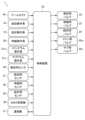
制御装置32は、各操作弁を介してクレーン1の各アクチュエータを制御する。制御装置32は、キャビン17内に設けられている。制御装置35は、実体的には、CPU、ROM、RAM、HDD等がバスで接続される構成であってもよく、あるいはワンチップのLSI等からなる構成であってもよい。
The
制御装置32は、各種切換バルブ(旋回用バルブ22、伸縮用バルブ23、起伏用バルブ24、メイン用バルブ25mおよびサブ用バルブ25s)を制御するコンピュータである。制御装置32は、各種切換バルブ(22、23、24、25m、25s)を制御するために種々のプログラムやデータが格納されている。また、制御装置32は、各種センサ(巻回用センサ26、旋回用センサ27、伸縮用センサ28および起伏用センサ29)に接続されている。さらに、制御装置32は、各種操作具(旋回操作具18、起伏操作具19、伸縮操作具20、メインドラム操作具21mおよびサブドラム操作具21s)に接続されている。そのため、制御装置32は、各種操作具(18、19、20、21m、21s)の操作量に対応した制御信号を生成することができる。
The
また、制御装置32は、クレーン1による自動搬送を行う場合には、与えられた経路情報に基づいて、各種切換バルブ(旋回用バルブ22、伸縮用バルブ23、起伏用バルブ24、メイン用バルブ25mおよびサブ用バルブ25s)を制御する制御信号を生成することができる。
Further, when automatic transportation is performed by the
このように構成されるクレーン1は、車両2を走行させることで任意の位置にクレーン装置6を移動させることができる。また、クレーン1は、ブーム9を起立させ、かつブーム9を伸長させることでクレーン装置6の揚程や作業半径を拡大することができる。そして、クレーン1は、ブーム9の旋回、起伏、伸縮およびサブワイヤロープ16の巻き上げ等の動きを単独または併用することによって荷物Wを移動させることができる。
The
[制御装置の詳細な構成]
制御装置32は、目標搬送時間設定部32a、目標搬送速度算出部32b、目標速度信号生成部32cを有している。
[Detailed configuration of control device]
The
目標搬送時間設定部32aは、制御装置32の一部であり、各区間に対して目標搬送時間Tiを設定する。
The target transport
目標搬送速度算出部32bは、制御装置32の一部であり、算出した各区間の目標搬送時間Tiと、各区間における荷物Wの移動距離に基づいて、目標搬送速度Viを算出する。
The target conveying
目標速度信号生成部32cは、制御装置32の一部であり、算出した各区間の目標搬送速度Viに基づいて、各区間において荷物Wを搬送する際のブーム9の起伏方向の目標速度信号VUと、旋回方向の目標速度信号VRと、ワイヤロープ(メインワイヤロープ14もしくはサブワイヤロープ16)の繰り入れおよび繰り出し方向の目標速度信号VWを生成する。
The target speed
なお、制御装置32は、ブームカメラ93で撮影した画像を画像処理することで、荷物Wの現在位置を検出することも可能である。あるいは、クレーン1は、GNSS受信機30をフック(メインフック10aあるいはサブフック11a)に取り付ける構成とすれば、制御装置32によって、GNSS受信機30が受信した信号に基づいて荷物Wの現在位置を検出することも可能である。
Note that the
[目標速度信号の生成手順]
次に、クレーン1の制御方法における目標速度信号の生成手順について説明する。
[Procedure for generating target speed signal]
Next, the procedure for generating the target speed signal in the control method for the
クレーン1に与えられる荷物Wの経路情報は、別途準備した経路情報生成手段によって、図4に示すような点群データP(n)として生成される(nは自然数である)。本実施形態では、外部サーバを経路情報生成手段としており、外部サーバと通信する通信機31を介して、クレーン1の制御装置32に経路情報たる点群データP(n)が取り込まれる(図2参照)。
The route information of the load W given to the
図4に示すように、点群データP(n)は、n個のノード(点)からなる情報であり、
各ノードは、荷物Wの通過点の座標の情報を含んでいる。ノードに添えた数字は、各ノードの通過順序を表している。即ち、ノードP1は荷物Wの1番目の通過点の座標データであり、ノードPnは荷物Wのn番目(最後)の通過点の座標データである。荷物Wの位置としては、例えば、荷物Wの重心位置の座標を用いる。
As shown in FIG. 4, the point cloud data P(n) is information consisting of n nodes (points),
Each node contains the information of the coordinates of the passage points of the cargo W. FIG. The numbers attached to the nodes represent the order of passage of each node. That is, the node P1 is the coordinate data of the first passing point of the parcel W, and the node Pn is the coordinate data of the n-th (last) passing point of the parcel W. FIG. As the position of the load W, for example, the coordinates of the center of gravity of the load W are used.
制御装置32は、点群データP(n)が与えられると、まず、各ノード間の目標搬送時間Tiを設定する。なお、以下の説明では、ノードとノードの間を区間と呼ぶ。制御装置32は、例えば、ユーザーが希望する搬送所要時間(始点から終点までの搬送に要する時間)を、各区間における搬送距離等を考慮して割り振って、目標搬送時間Tiを設定する。目標搬送時間の添え字iは、何番目の区間であるかを表している(iは自然数である)。
When receiving the point cloud data P(n), the
制御装置32は、各区間の目標搬送時間Tiを設定すると、次に、その目標搬送時間Tiに基づいて各区間の目標搬送速度Viを算出する。ここで算出する目標搬送速度Viは、各区間の距離を目標搬送時間Tiで割った値である。即ち、目標搬送速度Viは、区間内における荷物Wの平均搬送速度に相当する。
After setting the target conveying time Ti for each section, the
制御装置32は、各区間の目標搬送速度Viを算出すると、その目標搬送速度Viとクレーンモデルに基づいて、ブーム9の起伏方向の目標速度信号VUと、旋回方向の目標速度信号VRと、メインウインチ13あるいはサブウインチ15における各ワイヤロープ14・16の繰り入れおよび繰り出し方向の目標速度信号VWを算出し生成する。ここで言う「目標速度信号」とは、ブーム9を起伏方向および旋回方向に変位させる目標速度、および各ワイヤロープ14・16を繰り入れおよび繰り出し方向に変位させる目標速度を各アクチュエータに指示するための信号であり、各目標速度に係る情報を含んでいる。
After calculating the target conveying speed Vi for each section, the
[制限係数の算出]
クレーン1は、図5に示すように、起伏用油圧シリンダ92に作動油を供給する第1油圧ポンプFP1と、メインウインチ13あるいはサブウインチ15に作動油を供給する第2油圧ポンプFP2と、旋回用油圧モータ81に作動油を供給する第3油圧ポンプFP3を備えている。第1油圧ポンプFP1の吐出油量はQ1であり、第2油圧ポンプFP2の吐出油量はQ2であり、第3油圧ポンプFP3の吐出油量はQ3である。各油圧ポンプFP1~P3の吐出油量は、エンジン(図示せず)の回転数に依存する。
[Calculation of limiting factor]
As shown in FIG. 5, the
[起伏最大速度の算出]
目標速度信号VUが起伏用バルブ24に入力されると、目標速度信号VUに応じた開度で起伏用バルブ24が開き、作動油が起伏用油圧シリンダ92に供給される。なお、第1油圧ポンプFP1が供給する吐出油量Q1の作動油のうち、一部(量Q4)は、バイパスされてメインウインチ13あるいはサブウインチ15に供給される。即ち、起伏用油圧シリンダ92には、Q1-Q4の量の作動油が供給される。
[Calculation of maximum hoisting speed]
When the target speed signal VU is input to the hoisting
制御装置32は、このような作動油の供給条件における起伏用油圧シリンダ92の最大速度Vsmaxを算出する。そして、制御装置32は、算出した起伏用油圧シリンダ92の最大速度Vsmaxに基づいて、ブーム9の起伏最大速度VUmaxを算出する。
The
[ワイヤ最大速度の算出]
目標速度信号VWがメイン用バルブ25mあるいはサブ用バルブ25sに入力されると、目標速度信号VWに応じた開度でメイン用バルブ25mあるいはサブ用バルブ25sが開き、作動油がメインウインチ13あるいはサブウインチ15に供給される。なお、メインウインチ13あるいはサブウインチ15には、第2油圧ポンプFP2が供給する吐出油量Q2の作動油と、第1油圧ポンプFP1よりバイパスされた量Q4の作動油を合わせて供給される。即ち、メインウインチ13あるいはサブウインチ15には、Q2+Q4の量の作動油が供給される。
[Calculation of maximum wire speed]
When the target speed signal VW is inputted to the
制御装置32は、このような作動油の供給条件におけるメインウインチ13あるいはサブウインチ15のウインチ最大速度Vdmaxを算出する。そして、制御装置32は、算出したメインウインチ13あるいはサブウインチ15のウインチ最大速度Vdmaxに基づいて、メインワイヤロープ14あるいはサブワイヤロープ16の繰り入れおよび繰り出しのワイヤ最大速度VWmaxを算出する。
The
[旋回最大速度の算出]
目標速度信号VRが旋回用バルブ22に入力されると、目標速度信号VRがに応じた開度で旋回用バルブ22が開き、作動油が旋回用油圧モータ81に供給される。なお、旋回用油圧モータ81には、第3油圧ポンプFP3が供給する吐出油量Q3の作動油が供給される。
[Calculation of maximum turning speed]
When the target speed signal VR is input to the turning
制御装置32は、このような作動油の供給条件における旋回用油圧モータ81の旋回最大速度VRmaxを算出する。
The
[最大速度の比較]
制御装置32は、上記のようにして算出したブーム9の起伏最大速度VUmaxと目標速度信号VUとを比較する。ここで、目標速度信号VUが起伏最大速度VUmaxを越えている場合には、現実的には目標速度信号VUよりも小さい起伏最大速度VUmaxでしかブーム9を動作させることができないこととなる。即ち、この場合、ブーム9は、作業者が意図した操作通りに起伏動作をすることができない。
[Comparison of maximum speed]
The
制御装置32は、目標速度信号VUが起伏最大速度VUmaxを越えている場合には、制限係数X1を算出する。制限係数X1は、VUmax/VUで算出される、0を超え1未満の値である。
The
[最大速度の比較]
また、制御装置32は、上記のようにして算出したメインワイヤロープ14あるいはサブワイヤロープ16の繰り入れおよび繰り出しのワイヤ最大速度VWmaxと目標速度信号VWとを比較する。ここで、目標速度信号VWがワイヤ最大速度VWmaxを越えている場合には、現実的には目標速度信号VWよりも小さいワイヤ最大速度VWmaxでしかメインワイヤロープ14あるいはサブワイヤロープ16の繰り入れおよび繰り出し動作させることができないこととなる。即ち、この場合、メインワイヤロープ14あるいはサブワイヤロープ16は、作業者が意図した操作通りに繰り入れおよび繰り出し動作をすることができない。
[Comparison of maximum speed]
The
制御装置32は、目標速度信号VWがワイヤ最大速度VWmaxを越えている場合には、制限係数X2を算出する。制限係数X2は、VWmax/VWで算出される、0を超え1未満の値である。
The
[最大速度の比較]
制御装置32は、上記のようにして算出したブーム9の旋回最大速度VRmaxと目標速度信号VRとを比較する。ここで、目標速度信号VRが旋回最大速度VRmaxを越えている場合には、現実的には目標速度信号VRよりも小さい旋回最大速度VRmaxでしかブーム9を旋回させることができないこととなる。即ち、この場合、ブーム9は、作業者が意図した操作通りに旋回動作をすることができない。
[Comparison of maximum speed]
The
制御装置32は、目標速度信号VRが旋回最大速度VRmaxを越えている場合には、制限係数X3を算出する。制限係数X3は、VRmax/VRで算出される、0を超え1未満の値である。
The
[最大速度の制限]
制御装置32は、制限係数X1~X3のうち、一つでも制限係数が算出された場合には、全てのアクチュエータ(即ち、起伏用油圧シリンダ92とメインウインチ13あるいはサブウインチ15と旋回用油圧モータ81)の目標速度信号を制限する。例えば、制限係数X1が算出された場合には、全ての目標速度信号VU・VW・VRに制限係数X1を乗じる。なお、制御装置32は、複数の制限係数が算出された場合には、算出された制限係数のうち、最も値が小さい制限係数を採用する。なお、図5に示した油圧回路は例示であり、他の構成を有する油圧回路を備えた装置(例えばクレーン以外の装置)においても、
本実施形態で示した制御方法を適用することができ、油圧回路上の各アクチュエータにおける流量の上限値を考慮することで、装置に意図した動作をさせることが可能になる。
[Maximum speed limit]
When at least one of the limiting coefficients X1 to X3 is calculated, the
The control method shown in this embodiment can be applied, and by considering the upper limit value of the flow rate in each actuator on the hydraulic circuit, it is possible to cause the device to operate as intended.
[最大速度の制限効果]
全ての目標速度信号VU・VW・VRに同じ制限係数を乗じると、各目標速度信号VU・VW・VRの速度バランスを維持しながら、実際に動作可能な最大速度を超えていた目標速度信号を動作可能な最大速度以下に制限することができる。
[Maximum speed limit effect]
By multiplying all the target speed signals VU, VW and VR by the same limiting factor, the target speed signals exceeding the maximum speed at which the actual operation is possible can be eliminated while maintaining the speed balance of each of the target speed signals VU, VW and VR. Can be limited to below maximum operable speed.
図6には、目標速度信号に制限を加えたときの目標搬送時間Tiの設定状況と目標速度信号の変化と最大速度との関係を模式的に示しており、図7には、目標速度信号に制限を加えないときの目標搬送時間Tiの設定状況と目標速度信号の変化と最大速度との関係を模式的に示している。 FIG. 6 schematically shows the relationship between the setting of the target transfer time Ti, the change in the target speed signal, and the maximum speed when the target speed signal is limited. 4 schematically shows the relationship between the setting state of the target transfer time Ti, the change in the target speed signal, and the maximum speed when no limitation is applied to .
目標速度信号に制限を加えない場合、図7に示すように、第3区間およびその近傍において、各アクチュエータの目標速度のうちブーム9の起伏方向の目標速度信号VUが最大速度を超えている。このため、第3区間の付近においては、設定した経路に沿って荷物Wを搬送することができない。また、このような場合には、自動搬送中に荷物Wの振れが発生することも予測される。
When the target speed signal is not limited, as shown in FIG. 7, the target speed signal VU in the hoisting direction of the
一方、目標速度信号に制限を加えた場合、図6に示すように、第3区間の目標搬送時間T3を延長させることで、各アクチュエータの目標速度(ここではブーム9の起伏方向の目標速度信号VU)が最大速度を超えることを防いでいる。このため、第3区間の付近においても、設定した経路に沿って荷物Wを搬送することができ、自動搬送中における荷物Wの振れを抑制することができる。なお、目標速度信号に制限を加えた場合、始点から終点に至るまでの自動搬送に要する全体時間は延びる傾向となる。 On the other hand, when the target speed signal is limited, as shown in FIG. 6, the target speed of each actuator (here, the target speed signal VU) is prevented from exceeding the maximum speed. Therefore, even in the vicinity of the third section, the load W can be transported along the set route, and the swing of the load W during automatic transport can be suppressed. When the target speed signal is restricted, the total time required for automatic transportation from the start point to the end point tends to increase.
[第1の実施形態に係る制御フロー]
次に、より具体的な制御フローに沿って、クレーン1の制御方法について説明する。クレーン1は、図8(A)に示すような第1の実施形態に係る制御フローに従って、荷物Wを自動搬送することができる。
[Control flow according to the first embodiment]
Next, a control method for the
クレーン1では、図8(A)に示すように、ユーザーが入力手段(例えば、ジョイスティック等)によって、区間における速度司令(加速あるいは減速)を行う(STEP-101)。ここでの速度司令は、その区間における目標搬送速度Viとなる。
In the
次に、制御装置32は、目標搬送速度Viに基づいて、ブーム9の起伏方向の目標速度信号VUと、旋回方向の目標速度信号VRと、メインワイヤロープ14あるいはサブワイヤロープ16の繰り入れおよび繰り出し方向の目標速度信号VWを生成する(STEP-102)。
Next, based on the target conveying speed Vi, the
次に、制御装置32は、各目標速度信号VU・VW・VRを、各アクチュエータの最大速度VUmax・VWmax・VRmaxと比較し、各目標速度信号VU・VW・VRが、各アクチュエータの最大速度VUmax・VWmax・VRmaxを越えていないかどうかを確認する(STEP-103)。
Next, the
次に、各目標速度信号VU・VW・VRのうち、アクチュエータの最大速度を越えているものがあった場合には、全ての目標速度信号VU・VW・VRに係数を乗じて修正する(STEP-104)。 Next, if any of the target speed signals VU, VW, and VR exceeds the maximum speed of the actuator, all the target speed signals VU, VW, and VR are corrected by multiplying them by coefficients (STEP -104).
制御装置32は、与えられた経路情報(点群データP(n))に基づいた自動搬送制御を実行する前に、以下の処理をプレ処理として実行する。制御装置32は、与えられた経路情報(点群データP(n))に基づいて、予め区間ごとに目標搬送時間Tiを設定し、各区間において、各目標速度信号VU・VW・VRと、各アクチュエータの最大速度VUmax・VWmax・VRmaxと比較して、各目標速度信号VU・VW・VRが、各アクチュエータの最大速度VUmax・VWmax・VRmaxを越える区間を特定しておく。また、制御装置32は、各目標速度信号VU・VW・VRが、各アクチュエータの最大速度VUmax・VWmax・VRmaxを越える区間において、全ての目標速度信号VU・VW・VRを修正するための係数(各係数X1~X3)を予め算出しておく。
The
次に、制御装置32は、修正後の目標速度信号VU・VW・VRに基づいて、クレーン1を制御する(STEP-105)。
Next, the
次に、制御装置32は、クレーン1の動作後に、各アクチュエータの実際の動作速度を検出し、修正後の目標速度信号VU・VW・VRに基づいて指示した速度との差異を求め、この差異を目標速度信号VU・VW・VRにフィードバックする(STEP-106)。これにより、経路情報(点群データP(n))に基づいて設定した経路と、荷物Wが実際の移動した経路との差異を少なくしている。
Next, the
[第2の実施形態に係る制御フロー]
また、クレーン1が荷物Wの位置情報をリアルタイムに検出することができる手段(例えば、ブームカメラ93やGNSS受信機30等)を備えている場合には、図8(B)に示すような第2の実施形態に係る制御フローに従って、荷物Wを自動搬送することができ、吊荷の位置情報を用いたフィードバック制御を併用することによって、クレーン1における経路情報を用いた自動搬送制御のロバスト性を向上させることができる。
[Control flow according to the second embodiment]
Moreover, when the
クレーン1では、図8(B)に示すように、ユーザーが入力手段(例えば、ジョイスティック等)によって、区間における速度司令(加速あるいは減速)を行う(STEP-201)。ここでの速度司令は、その区間における目標搬送速度Viとなる。
In the
次に、制御装置32は、入力された目標搬送速度Viに基づいて、ブーム9の起伏方向の目標速度信号VUと、旋回方向の目標速度信号VRと、メインワイヤロープ14あるいはサブワイヤロープ16の繰り入れおよび繰り出しの目標速度信号VWを生成する(STEP-202)。
Next, the
次に、制御装置32は、各目標速度信号VU・VW・VRを、各アクチュエータの最大速度VUmax・VWmax・VRmaxと比較し、各目標速度信号VU・VW・VRが、各アクチュエータの最大速度VUmax・VWmax・VRmaxを越えていないかどうかを確認する(STEP-203)。
Next, the
次に、各目標速度信号VU・VW・VRのうち、アクチュエータの最大速度を越えているものがあった場合には、全ての目標速度信号VU・VW・VRに係数を乗じて修正する(STEP-204)。 Next, if any of the target speed signals VU, VW, and VR exceeds the maximum speed of the actuator, all the target speed signals VU, VW, and VR are corrected by multiplying them by coefficients (STEP -204).
制御装置32は、経路情報(点群データP(n))に基づいて設定した経路に沿った自動搬送制御を実行する前に、以下の処理をプレ処理として実行する。制御装置32は、与えられた経路情報(点群データP(n))に基づいて、予め区間ごとに目標搬送時間Tiを設定し、各区間において、各目標速度信号VU・VW・VRと、各アクチュエータの最大速度VUmax・VWmax・VRmaxと比較して、各目標速度信号VU・VW・VRが、各アクチュエータの最大速度VUmax・VWmax・VRmaxを越える区間を特定しておく。また、制御装置32は、各目標速度信号VU・VW・VRが、各アクチュエータの最大速度VUmax・VWmax・VRmaxを越える区間において、全ての目標速度信号VU・VW・VRを修正するための係数(各係数X1~X3)を予め算出しておく。
The
次に、制御装置32は、修正後の目標速度信号VU・VW・VRに基づいて、クレーン1を制御する(STEP-205)。
Next, the
次に、制御装置32は、クレーン1の動作後において、各アクチュエータの実際の動作速度を検出し、(STEP-202)で算出された(即ち、修正前の)各目標速度信号VU・VW・VRに係る速度との差異を求め、この差異を修正後の目標速度信号VU・VW・VRにフィードバックする(STEP-206)。これにより、与えられた経路情報(点群データP(n))に基づいて設定した経路と、荷物Wが実際の移動した経路との差異を少なくしている。
Next, the
さらに、制御装置32は、クレーン1の動作後において、荷物Wの実際の位置を検出し、荷物Wの位置から、現在荷物Wが位置している区間を判断する(STEP-207)。制御装置32は、ここでの判断に基づいて現在荷物Wが位置している区間を特定し、その特定した区間における条件のもと、さらに(STEP-201)を実行する。これにより、与えられた経路情報(点群データP(n))に、基づいて設定した経路と、実際の荷物Wの移動経路とを比較し、その差異をなくすように制御しながら自動搬送を行うことができるため、外乱の影響を受けても、荷物Wを確実に設定した経路に沿わせつつ自動搬送することができる。
Further, the
即ち、本発明に係るクレーン1の制御方法によれば、クレーン1を用いて、与えられた経路情報(点群データP(n))に基づいて設定した搬送経路に沿って荷物Wを自動搬送する際に、荷物Wを確実に搬送経路に沿って搬送することができる。
That is, according to the control method of the
上述の実施形態は、代表的な形態を示したに過ぎず、一実施形態の骨子を逸脱しない範囲で種々変形して実施することができる。さらに種々なる形態で実施し得ることは勿論のことであり、本発明の範囲は、特許請求の範囲の記載によって示され、さらに特許請求の範囲に記載の均等の意味、および範囲内のすべての変更を含む。 The above-described embodiment merely shows typical forms, and various modifications can be made without departing from the gist of one embodiment. It goes without saying that it can be embodied in various forms, and the scope of the present invention is indicated by the description of the scope of the claims. Including changes.
1 クレーン
9 ブーム
32 制御装置
Ti 目標搬送時間
Vi 目標搬送速度
VU (ブームの起伏方向の)目標速度信号
VW (ワイヤロープの繰り入れおよび繰り出し方向の)目標速度信号
VR (ブームの旋回方向の)目標速度信号
VUmax 起伏最大速度
VWmax ワイヤ最大速度
VRmax 旋回最大速度
W 荷物
X1 第1係数
X2 第2係数
X3 第3係数
1
Claims (6)
前記制御装置によって、
通過順序が隣り合う二つの通過点で規定された区間における前記荷物の目標搬送時間を設定し、
前記二つの通過点間の距離と前記目標搬送時間より前記区間における前記荷物の目標搬送速度を算出し、
前記目標搬送速度より、該目標搬送速度を実現するための前記ブームの起伏速度および旋回速度、および前記ワイヤロープの繰り入れおよび繰り出し速度を指示するための各目標速度を算出し、
前記区間における前記ブームの起伏速度および旋回速度、および前記ワイヤロープの繰り入れおよび繰り出しの速度の各最大速度を算出し、
前記区間における前記各目標速度と対応する前記各最大速度とを比較し、前記目標速度が対応する前記最大速度を超えているものが存在する場合に、前記各目標速度に、0を超えて1未満の値である係数を乗じて、前記各目標速度がそれぞれの対応する前記最大速度未満となるように制限を加え、
制限を加えた前記各目標速度に基づいて前記クレーンを制御する、
ことを特徴とするクレーンの制御方法。 The control device controls the hoisting and turning motions of the boom, and the feeding and feeding motions of the wire rope, along the conveying route given as point cloud data including at least the coordinates of the passing points of the load and the passing order of each passing point. A control method for a crane that automatically conveys the load by
By said controller,
setting a target transport time for the cargo in a section defined by two passing points that are adjacent in passing order;
calculating a target transport speed of the cargo in the section from the distance between the two passing points and the target transport time;
From the target transport speed, each target speed for instructing the hoisting speed and turning speed of the boom for realizing the target transport speed and the feeding and unloading speed of the wire rope is calculated;
Calculate each maximum speed of the boom hoisting speed and turning speed in the section, and the speed of retracting and retracting the wire rope,
Each target speed in the section is compared with each corresponding maximum speed, and if there is a target speed exceeding the corresponding maximum speed, each target speed exceeds 0 and is 1 limiting each target speed to be less than its corresponding maximum speed by multiplying by a factor that is less than
controlling the crane based on each of the limited target speeds;
A crane control method characterized by:
対応する前記最大速度を超えている前記目標速度が一つ存在する場合に、
前記目標速度が対応する前記最大速度を超えているものの前記最大速度を前記目標速度で除して、前記係数を算出する、
ことを特徴とする請求項1に記載のクレーンの制御方法。 By said controller,
If there is one target speed that exceeds the corresponding maximum speed,
calculating the factor by dividing the maximum speed for which the target speed exceeds the corresponding maximum speed by the target speed;
The crane control method according to claim 1, characterized in that:
対応する前記最大速度を超えている前記目標速度が複数存在する場合に、
前記目標速度が対応する前記最大速度を超えているものの前記最大速度を前記目標速度で除して算出した値のうち最も小さい値を前記係数とする、
ことを特徴とする請求項1に記載のクレーンの制御方法。 By said controller,
When there are multiple target velocities exceeding the corresponding maximum velocities,
The smallest value among the values calculated by dividing the maximum speed by the target speed for which the target speed exceeds the corresponding maximum speed is set as the coefficient.
The crane control method according to claim 1, characterized in that:
前記制限を加えた各目標速度を、
前記荷物の自動搬送を開始する前に算出する、
ことを特徴とする請求項1から請求項3の何れか一項に記載のクレーンの制御方法。 By said controller,
Each target speed with the above limit added,
Calculated before starting automatic transportation of the package,
The crane control method according to any one of claims 1 to 3, characterized in that:
前記制限を加えた各目標速度を、
前記区間ごとに算出する、
ことを特徴とする請求項4に記載のクレーンの制御方法。 By said controller,
Each target speed with the above limit added,
calculating for each interval;
The crane control method according to claim 4, characterized in that:
Priority Applications (5)
| Application Number | Priority Date | Filing Date | Title |
|---|---|---|---|
| JP2019061193A JP7247703B2 (en) | 2019-03-27 | 2019-03-27 | Crane control method and crane |
| PCT/JP2020/013905 WO2020196809A1 (en) | 2019-03-27 | 2020-03-27 | Crane control method and crane |
| US17/423,294 US12180042B2 (en) | 2019-03-27 | 2020-03-27 | Crane control method and crane |
| EP20779855.4A EP3950559A4 (en) | 2019-03-27 | 2020-03-27 | CRANE CONTROL PROCEDURES AND CRANE |
| CN202080021675.8A CN113574005B (en) | 2019-03-27 | 2020-03-27 | Crane control devices and cranes |
Applications Claiming Priority (1)
| Application Number | Priority Date | Filing Date | Title |
|---|---|---|---|
| JP2019061193A JP7247703B2 (en) | 2019-03-27 | 2019-03-27 | Crane control method and crane |
Publications (2)
| Publication Number | Publication Date |
|---|---|
| JP2020158279A JP2020158279A (en) | 2020-10-01 |
| JP7247703B2 true JP7247703B2 (en) | 2023-03-29 |
Family
ID=72608474
Family Applications (1)
| Application Number | Title | Priority Date | Filing Date |
|---|---|---|---|
| JP2019061193A Active JP7247703B2 (en) | 2019-03-27 | 2019-03-27 | Crane control method and crane |
Country Status (5)
| Country | Link |
|---|---|
| US (1) | US12180042B2 (en) |
| EP (1) | EP3950559A4 (en) |
| JP (1) | JP7247703B2 (en) |
| CN (1) | CN113574005B (en) |
| WO (1) | WO2020196809A1 (en) |
Families Citing this family (5)
| Publication number | Priority date | Publication date | Assignee | Title |
|---|---|---|---|---|
| DE102019113881A1 (en) * | 2019-02-12 | 2020-08-13 | Putzmeister Engineering Gmbh | Concrete pump and method of supporting a concrete pump |
| WO2022141458A1 (en) * | 2020-12-31 | 2022-07-07 | 中联重科股份有限公司 | Hoisting control method and system, and engineering machine |
| US12195306B2 (en) * | 2021-04-12 | 2025-01-14 | Structural Services, Inc. | Systems and methods for identifying and locating building material objects |
| AU2022258326A1 (en) * | 2021-04-12 | 2023-11-23 | Structural Services, Inc. | Systems and methods for assisting a crane operator |
| JP2023174568A (en) * | 2022-05-27 | 2023-12-07 | マニタウォック クレイン カンパニーズ, エルエルシー | Crane telescoping boom, system and method for actuating crane telescoping boom |
Citations (4)
| Publication number | Priority date | Publication date | Assignee | Title |
|---|---|---|---|---|
| WO2016148241A1 (en) | 2015-03-19 | 2016-09-22 | 株式会社タダノ | Pivoting device |
| JP2016169091A (en) | 2015-03-13 | 2016-09-23 | 国立大学法人三重大学 | Single pendulum type transport device |
| JP2017202912A (en) | 2016-05-12 | 2017-11-16 | Jfe物流株式会社 | Crane steady rest control method and system |
| WO2018105740A1 (en) | 2016-12-09 | 2018-06-14 | 株式会社タダノ | Crane |
Family Cites Families (14)
| Publication number | Priority date | Publication date | Assignee | Title |
|---|---|---|---|---|
| US7426423B2 (en) * | 2003-05-30 | 2008-09-16 | Liebherr-Werk Nenzing—GmbH | Crane or excavator for handling a cable-suspended load provided with optimised motion guidance |
| US8005598B2 (en) * | 2003-08-05 | 2011-08-23 | Sintokogio, Ltd. | Crane and controller thereof |
| DE102007039408A1 (en) * | 2007-05-16 | 2008-11-20 | Liebherr-Werk Nenzing Gmbh | Crane control system for crane with cable for load lifting by controlling signal tower of crane, has sensor unit for determining cable angle relative to gravitational force |
| CN101717043B (en) * | 2009-12-04 | 2012-07-04 | 常州东方机电成套有限公司 | High-precision synchronous control system and method of crane operations of bridge type crane |
| RU2440924C1 (en) * | 2010-06-08 | 2012-01-27 | Государственное образовательное учреждение высшего профессионального образования "Тульский государственный университет" (ТулГУ) | Method of crane operation control |
| JP5686404B2 (en) * | 2010-08-23 | 2015-03-18 | 株式会社奥村組 | Crane control method |
| FI20115922A0 (en) * | 2011-09-20 | 2011-09-20 | Konecranes Oyj | Crane control |
| DE102012004914A1 (en) * | 2012-03-09 | 2013-09-12 | Liebherr-Werk Nenzing Gmbh | Crane control with rope power mode |
| JP5303061B1 (en) * | 2012-11-20 | 2013-10-02 | 株式会社小松製作所 | Engine control device and construction machine |
| DE102016106427B3 (en) * | 2016-04-08 | 2017-03-23 | Reschwitzer Saugbagger Produktions Gmbh | Method for controlling the movement of a flexible hose carrier of a suction dredger |
| JP6693246B2 (en) * | 2016-04-08 | 2020-05-13 | 株式会社タダノ | crane |
| JP6177400B1 (en) * | 2016-08-25 | 2017-08-09 | 株式会社タダノ | Crane truck |
| FR3071240B1 (en) * | 2017-09-21 | 2019-09-06 | Manitowoc Crane Group France | DYNAMIC OPTIMIZATION OF A CRANE LOAD CURVE |
| CN108545614A (en) * | 2018-04-09 | 2018-09-18 | 武汉理工大学 | Full-automatic bridge-type storage crane job autocontrol method |
-
2019
- 2019-03-27 JP JP2019061193A patent/JP7247703B2/en active Active
-
2020
- 2020-03-27 WO PCT/JP2020/013905 patent/WO2020196809A1/en not_active Ceased
- 2020-03-27 EP EP20779855.4A patent/EP3950559A4/en active Pending
- 2020-03-27 US US17/423,294 patent/US12180042B2/en active Active
- 2020-03-27 CN CN202080021675.8A patent/CN113574005B/en active Active
Patent Citations (4)
| Publication number | Priority date | Publication date | Assignee | Title |
|---|---|---|---|---|
| JP2016169091A (en) | 2015-03-13 | 2016-09-23 | 国立大学法人三重大学 | Single pendulum type transport device |
| WO2016148241A1 (en) | 2015-03-19 | 2016-09-22 | 株式会社タダノ | Pivoting device |
| JP2017202912A (en) | 2016-05-12 | 2017-11-16 | Jfe物流株式会社 | Crane steady rest control method and system |
| WO2018105740A1 (en) | 2016-12-09 | 2018-06-14 | 株式会社タダノ | Crane |
Also Published As
| Publication number | Publication date |
|---|---|
| CN113574005B (en) | 2024-03-05 |
| US20220081263A1 (en) | 2022-03-17 |
| US12180042B2 (en) | 2024-12-31 |
| EP3950559A1 (en) | 2022-02-09 |
| CN113574005A (en) | 2021-10-29 |
| EP3950559A4 (en) | 2022-12-21 |
| JP2020158279A (en) | 2020-10-01 |
| WO2020196809A1 (en) | 2020-10-01 |
Similar Documents
| Publication | Publication Date | Title |
|---|---|---|
| JP7247703B2 (en) | Crane control method and crane | |
| JP7293795B2 (en) | Crane control method and crane | |
| JP7192527B2 (en) | crane | |
| CN113382948B (en) | Crane and route generation system for crane | |
| JP7172243B2 (en) | Cranes and crane control systems | |
| JP7172199B2 (en) | Remote control terminal and work vehicle | |
| JP7151223B2 (en) | Cranes and crane control methods | |
| CN112912332B (en) | Crane device | |
| JP7173176B2 (en) | Crane and path generation system | |
| JP7176645B2 (en) | control system and crane | |
| JP7255601B2 (en) | Work machine and work machine contact monitoring system | |
| JP7172256B2 (en) | crane | |
| JP7513999B2 (en) | CONTROL DEVICE, CRANE, AND CRANE CONTROL METHOD | |
| JP7159899B2 (en) | Crane and crane path generation system | |
| JP7243260B2 (en) | Crane and crane path generation system | |
| JP7167759B2 (en) | Crane and crane path generation system | |
| JP7501098B2 (en) | Boom camera system and mobile crane equipped with boom camera system | |
| JP2003081577A (en) | Crane hook horizontal movement control device | |
| JP2003081578A (en) | Crane hook horizontal movement control device |
Legal Events
| Date | Code | Title | Description |
|---|---|---|---|
| A521 | Request for written amendment filed |
Free format text: JAPANESE INTERMEDIATE CODE: A523 Effective date: 20200214 |
|
| A621 | Written request for application examination |
Free format text: JAPANESE INTERMEDIATE CODE: A621 Effective date: 20220307 |
|
| TRDD | Decision of grant or rejection written | ||
| A01 | Written decision to grant a patent or to grant a registration (utility model) |
Free format text: JAPANESE INTERMEDIATE CODE: A01 Effective date: 20230214 |
|
| A61 | First payment of annual fees (during grant procedure) |
Free format text: JAPANESE INTERMEDIATE CODE: A61 Effective date: 20230227 |
|
| R150 | Certificate of patent or registration of utility model |
Ref document number: 7247703 Country of ref document: JP Free format text: JAPANESE INTERMEDIATE CODE: R150 |
|
| R250 | Receipt of annual fees |
Free format text: JAPANESE INTERMEDIATE CODE: R250 |