JP7278024B2 - gearbox controller - Google Patents
gearbox controller Download PDFInfo
- Publication number
- JP7278024B2 JP7278024B2 JP2017073308A JP2017073308A JP7278024B2 JP 7278024 B2 JP7278024 B2 JP 7278024B2 JP 2017073308 A JP2017073308 A JP 2017073308A JP 2017073308 A JP2017073308 A JP 2017073308A JP 7278024 B2 JP7278024 B2 JP 7278024B2
- Authority
- JP
- Japan
- Prior art keywords
- engagement
- engagement element
- hydraulic pressure
- mode
- gear
- Prior art date
- Legal status (The legal status is an assumption and is not a legal conclusion. Google has not performed a legal analysis and makes no representation as to the accuracy of the status listed.)
- Active
Links
Images






Landscapes
- Control Of Transmission Device (AREA)
- Transmission Devices (AREA)
Description
本発明は、インプット軸(入力軸)に入力される動力を2系統に分割してアウトプット軸(出力軸)に伝達可能な変速機とともに車両に搭載される制御装置に関する。
BACKGROUND OF THE
自動車などの車両に搭載される変速機として、エンジンの動力を無段階に変速する無段変速機構と、エンジンの動力を無段変速機構を経由せずに伝達する歯車機構と、無段変速機構からの動力と歯車機構からの動力とを合成するための遊星歯車機構とを備えたものが提案されている。この変速機では、エンジンからの動力を無段変速機構と歯車機構とに分割し、その分割された各動力を遊星歯車機構で合成して車輪に伝達することができる。 Transmissions mounted on vehicles such as automobiles include a continuously variable transmission mechanism that continuously changes the power of the engine, a gear mechanism that transmits the engine power without going through the continuously variable transmission mechanism, and a continuously variable transmission mechanism. It has been proposed to include a planetary gear mechanism for combining the power from the engine and the power from the gear mechanism. In this transmission, the power from the engine can be split between the continuously variable transmission mechanism and the gear mechanism, and the split power can be synthesized by the planetary gear mechanism and transmitted to the wheels.
駆動源の動力を2系統に分割して伝達可能な変速機は、動力分割式無段変速機として、出願人も提案している。 The applicant has also proposed a transmission capable of transmitting the power of a drive source by dividing it into two systems as a power split type continuously variable transmission.
その提案に係る動力分割式無段変速機には、無段変速機構、スプリット変速機構(平行軸式歯車機構)および遊星歯車機構が含まれる。無段変速機構は、公知のベルト式の無段変速機(CVT:Continuously Variable Transmission)と同様の構成を有している。無段変速機構のプライマリ軸には、インプット軸に入力されるエンジンの動力が伝達される。無段変速機構のセカンダリ軸は、遊星歯車機構のサンギヤに接続されている。スプリット変速機構は、インプット軸の動力が伝達/遮断されるスプリットドライブギヤと、スプリットドライブギヤとギヤ列を構成し、遊星歯車機構のキャリアと一体回転するスプリットドリブンギヤとを備えている。遊星歯車機構のリングギヤには、アウトプット軸が接続されている。アウトプット軸の回転は、デファレンシャルギヤに伝達され、デファレンシャルギヤから左右の駆動輪に伝達される。 The proposed power split type continuously variable transmission includes a continuously variable transmission mechanism, a split transmission mechanism (parallel shaft gear mechanism) and a planetary gear mechanism. The continuously variable transmission mechanism has the same configuration as a known belt-type continuously variable transmission (CVT: Continuously Variable Transmission). The power of the engine input to the input shaft is transmitted to the primary shaft of the continuously variable transmission mechanism. A secondary shaft of the continuously variable transmission is connected to the sun gear of the planetary gear mechanism. The split transmission mechanism includes a split drive gear that transmits/disconnects the power of the input shaft, and a split driven gear that forms a gear train with the split drive gear and rotates integrally with the carrier of the planetary gear mechanism. An output shaft is connected to the ring gear of the planetary gear mechanism. Rotation of the output shaft is transmitted to the differential gear, and from the differential gear to the left and right drive wheels.
この動力分割式無段変速機では、前進走行時における動力伝達モードとして、ベルトモードおよびスプリットモードが設けられている。 In this power split type continuously variable transmission, a belt mode and a split mode are provided as power transmission modes during forward running.
ベルトモードでは、遊星歯車機構のサンギヤとリングギヤとを結合/分離する第1クラッチが係合されて、サンギヤとリングギヤとが結合される。また、インプット軸とスプリットドライブギヤとの間での動力の伝達/遮断を切り替える第2クラッチが解放されて、スプリットドライブギヤが自由回転状態(フリー)にされ、遊星歯車機構のキャリアが自由回転状態にされる。そのため、無段変速機構から出力される動力により、サンギヤおよびリングギヤが一体的に回転し、アウトプット軸がリングギヤと一体的に回転する。したがって、ベルトモードでは、が無段変速機構の変速比(ベルト変速比)が大きいほど、そのベルト変速比に比例して、動力分割式無段変速機の変速比(インプット軸の回転数/アウトプット軸の回転数)であるユニット変速比が大きくなる。 In the belt mode, the first clutch that connects/disconnects the sun gear and the ring gear of the planetary gear mechanism is engaged to connect the sun gear and the ring gear. In addition, the second clutch that switches transmission/interruption of power between the input shaft and the split drive gear is released, the split drive gear is put in a free rotation state (free), and the carrier of the planetary gear mechanism is in a free rotation state. be made. Therefore, the power output from the continuously variable transmission mechanism rotates the sun gear and the ring gear integrally, and the output shaft rotates integrally with the ring gear. Therefore, in the belt mode, as the gear ratio of the continuously variable transmission mechanism (belt gear ratio) increases, the gear ratio of the power split type continuously variable transmission (rotational speed of input shaft/output) increases in proportion to the belt gear ratio. The unit transmission ratio, which is the number of revolutions of the transmission shaft), increases.
スプリットモードでは、第1クラッチが解放されて、遊星歯車機構のサンギヤとリングギヤとの結合が解除される。そのため、無段変速機構から出力される動力により、サンギヤが回転する。一方、第2クラッチが係合されて、インプット軸からスプリットドライブギヤに動力が伝達され、その動力がスプリットドライブギヤからスプリットドリブンギヤを介することにより一定のスプリット変速比で変速されて、遊星歯車機構のキャリアに入力される。そのため、スプリットモードでは、ベルト変速比が大きいほどユニット変速比が小さくなり、スプリット変速比以下の変速比を実現することができる。 In the split mode, the first clutch is released to disengage the sun gear and ring gear of the planetary gear mechanism. Therefore, the power output from the continuously variable transmission mechanism rotates the sun gear. On the other hand, when the second clutch is engaged, power is transmitted from the input shaft to the split drive gear, and the power is shifted from the split drive gear through the split driven gear at a constant split gear ratio, resulting in a planetary gear mechanism. entered into the carrier. Therefore, in the split mode, the larger the belt gear ratio, the smaller the unit gear ratio, and a gear ratio equal to or lower than the split gear ratio can be realized.
ユニット変速比がスプリット変速比を跨いで変更される場合、そのユニット変速比の変更には、ベルトモードとスプリットモードとの切り替えが伴う。このモードの切り替えは、第1クラッチと第2クラッチとの係合の切り替え(第1クラッチと第2クラッチとの掛け替え)により達成される。 If the unit transmission ratio is changed across a split transmission ratio, the change in unit transmission ratio is accompanied by switching between belt mode and split mode. This mode switching is achieved by switching engagement between the first clutch and the second clutch (switching between the first clutch and the second clutch).
ベルト変速比とスプリット変速比とがずれている状態では、サンギヤとキャリアとの間に差回転が生じているので、第1クラッチと第2クラッチとの係合が切り替えられると、その差回転による変速ショックが発生する場合がある。そのため、ベルト変速比がスプリット変速比とほぼ一致する状態において、解放側の第1クラッチまたは第2クラッチの油圧を低減させつつ、係合側の第2クラッチまたは第1クラッチの油圧を上昇させることにより、第1クラッチと第2クラッチとの係合とが切り替えられる。 When the belt gear ratio and the split gear ratio are deviated from each other, differential rotation occurs between the sun gear and the carrier. Shift shock may occur. Therefore, in a state in which the belt gear ratio substantially matches the split gear ratio, the hydraulic pressure of the engaging side second clutch or the first clutch is increased while the hydraulic pressure of the disengaging side first clutch or the second clutch is reduced. , the engagement between the first clutch and the second clutch is switched.
しかしながら、油圧の立ち上がりのばらつきなど、種々の要因により、ベルト変速比とスプリット変速比との間にずれが生じた状態で第1クラッチと第2クラッチとの係合が切り替えられる場合がある。 However, due to various factors such as variations in rise of hydraulic pressure, engagement of the first clutch and the second clutch may be switched in a state where there is a deviation between the belt gear ratio and the split gear ratio.
かかる課題は、出願人が提案している動力分割式無段変速機に限らず、インプット軸とアウトプット軸との間での動力伝達経路が互いに異なる第1モードと第2モードとの切り替えを第1モードでの変速比と第2モードでの変速比とが一致した状態で行うことができる変速機に共通する課題である。 This problem is not limited to the power split type continuously variable transmission proposed by the applicant, but it is necessary to switch between the first mode and the second mode in which the power transmission paths between the input shaft and the output shaft are different from each other. This is a problem common to transmissions that can be operated with the gear ratio in the first mode and the gear ratio in the second mode matching.
本発明の目的は、第1モードでの変速比と第2モードでの変速比とがずれた状態で第1モードと第2モードとの切り替えが行われることを抑制できる、変速機の制御装置を提供することである。 SUMMARY OF THE INVENTION An object of the present invention is a transmission control device capable of suppressing switching between a first mode and a second mode in a state where the gear ratio in the first mode and the gear ratio in the second mode are deviated from each other. is to provide
前記の目的を達成するため、本発明に係る変速機の制御装置は、インプット軸、アウトプット軸、インプット軸に入力される動力を無段階に変速する無段変速機構、ならびに油圧により係合/解放される第1係合要素および第2係合要素を含み、インプット軸とアウトプット軸との間で動力を伝達するモードとして、第1係合要素の係合および第2係合要素の解放により、第1モードが構成され、第1係合要素の解放および第2係合要素の係合により、第1モードと動力伝達経路が異なる第2モードが構成され、第1モードおよび第2モードの少なくとも一方において、無段変速機構を介して動力が伝達され、無段変速機構の変速比が特定の値をとる場合に、第1モードの動力伝達経路の変速比と第2モードの動力伝達経路の変速比とが一致するように構成された変速機の制御装置であって、無段変速機構の変速比を変更する変速制御手段と、第1係合要素の係合と第2係合要素の係合との切り替えに際して、第1モードでの変速比と第2モードでの変速比とが一致したことに応じて、解放側の第2係合要素または第1係合要素の油圧を当該解放側の第2係合要素または第1係合要素の係合が維持される油圧に保持したまま、係合側の第1係合要素または第2係合要素の油圧を当該係合側の第1係合要素または第2係合要素が係合する油圧に一気に上昇させる指令を出力するダブルクラッチ制御手段とを含む。 In order to achieve the above object, a transmission control device according to the present invention includes an input shaft, an output shaft, a continuously variable transmission mechanism for steplessly shifting power input to the input shaft, and engagement/disengagement by hydraulic pressure. Engagement of the first engagement element and release of the second engagement element as a mode of transmitting power between the input shaft and the output shaft, including the first engagement element and the second engagement element that are released A first mode is configured by disengaging the first engaging element and engaging the second engaging element, thereby configuring a second mode having a different power transmission path from the first mode. In at least one of the above, when power is transmitted via a continuously variable transmission mechanism and the transmission gear ratio of the continuously variable transmission mechanism takes a specific value, the gear ratio of the power transmission path in the first mode and the power transmission in the second mode A control device for a transmission configured to match the gear ratio of a path, comprising gear shift control means for changing the gear ratio of a continuously variable transmission mechanism, engagement of a first engagement element, and engagement of a second engagement element. At the time of switching between engagement and engagement of the elements, the oil pressure of the second engagement element on the disengagement side or the first engagement element is increased according to the fact that the gear ratio in the first mode matches the gear ratio in the second mode. While maintaining the hydraulic pressure for maintaining the engagement of the second engagement element or the first engagement element on the release side, the hydraulic pressure of the first engagement element or the second engagement element on the engagement side is changed to the engagement side. and double clutch control means for outputting a command to raise the hydraulic pressure at which the first engagement element or the second engagement element of the clutch is engaged.
この構成によれば、第1係合要素が係合され、第2係合要素が解放された状態では、第1モードが構成される。一方、第1係合要素が解放され、第2係合要素が係合された状態では、第2モードが構成される。第1モードおよび第2モードの少なくとも一方では、インプット軸とアウトプット軸との間で無段変速機構を介して動力が伝達される。また、無段変速機構の変速比が特定の値をとる場合に、第1モードでの変速比と第2モードでの変速比とが一致する。 According to this configuration, the first mode is configured when the first engagement element is engaged and the second engagement element is released. On the other hand, the second mode is configured when the first engagement element is released and the second engagement element is engaged. In at least one of the first mode and the second mode, power is transmitted between the input shaft and the output shaft via the continuously variable transmission. Further, when the gear ratio of the continuously variable transmission mechanism takes a specific value, the gear ratio in the first mode and the gear ratio in the second mode match.
第1係合要素と第2係合要素との係合の切り替えの際には、無段変速機構の変速比が特定の値に向けて変更される。そして、無段変速機構の変速比が特定の値と一致したことに応じて、ダブルクラッチ制御が実施され、解放側の第2係合要素または第1係合要素の係合を保持、つまり解放側の第2/第1係合要素の油圧の指令値を当該解放側の第2係合要素または第1係合要素の係合が維持される油圧に応じた指令値に保持したまま、係合側の第1係合要素または第2係合要素の油圧の指令値が当該係合側の第1係合要素または第2係合要素が係合する油圧に応じた指令値に一気に上げられて、係合側の第1係合要素または第2係合要素が係合する。 When switching the engagement between the first engagement element and the second engagement element, the gear ratio of the continuously variable transmission is changed toward a specific value. Then, when the gear ratio of the continuously variable transmission mechanism matches a specific value, double clutch control is performed to hold or release the engagement of the second engagement element or the first engagement element on the disengagement side. While maintaining the command value of the hydraulic pressure of the second/first engagement element on the release side at a command value corresponding to the hydraulic pressure at which the engagement of the second engagement element or the first engagement element on the release side is maintained, The command value for the hydraulic pressure of the first engagement element or the second engagement element on the engagement side is suddenly increased to the command value corresponding to the hydraulic pressure at which the first engagement element or the second engagement element on the engagement side engages. , the first engaging element or the second engaging element on the engaging side engages.
かかるダブルクラッチ制御により、第1係合要素および/または第2係合要素の油圧の立ち上がりにばらつき(応答ばらつき)があっても、無段変速機構の変速比が特定の値と一致した状態で第1係合要素と第2係合要素との係合を切り替えることができる。そのため、無段変速機構の変速比が特定の値からずれた状態で第1係合要素と第2係合要素との係合の切り替えが行われることを抑制でき、無段変速機構の変速比が特定の値からずれた状態での当該切り替えによる変速ショックの発生を抑制できる。また、ダブルクラッチ制御中、第1係合要素の伝達トルク容量と第2係合要素の伝達トルク容量との合計がエンジントルクをはるかに上回ることにより、第1係合要素および第2係合要素の油圧の応答ばらつきを学習しなくても、エンジンの吹き上がりを抑制できる。 Due to such double clutch control, even if there is variation in the rise of the hydraulic pressure of the first engagement element and/or the second engagement element (response variation), the gear ratio of the continuously variable transmission mechanism can be maintained at a specific value. The engagement between the first engagement element and the second engagement element can be switched. Therefore, it is possible to suppress switching of the engagement between the first engagement element and the second engagement element in a state where the gear ratio of the continuously variable transmission mechanism deviates from a specific value. It is possible to suppress the occurrence of shift shock due to the switching in a state in which is deviated from a specific value. Further, during double clutch control, the sum of the transmission torque capacity of the first engagement element and the transmission torque capacity of the second engagement element far exceeds the engine torque, so that the first engagement element and the second engagement element It is possible to suppress engine racing without learning the oil pressure response variation.
さらには、係合側の第1係合要素または第2係合要素の油圧の指令値が一気に上げられるので、係合側の第1係合要素または第2係合要素の係合に要する時間を短縮でき、ひいては第1係合要素と第2係合要素との係合の切り替えに要する時間(変速時間)を短縮することができる。 Furthermore, since the hydraulic pressure command value for the first engagement element or the second engagement element on the engagement side is increased at once, the time required to engage the first engagement element or the second engagement element on the engagement side can be shortened, and the time required for switching the engagement between the first engagement element and the second engagement element (shift time) can be shortened.
制御装置は、変速制御手段により無段変速機構の変速比が特定の値に向けて変更されている間に、係合側の第1係合要素または第2係合要素に油圧を供給する準備制御を実施する準備制御手段をさらに含む構成であってもよい。 The control device prepares to supply hydraulic pressure to the first engagement element or the second engagement element on the engagement side while the gear ratio of the continuously variable transmission mechanism is changed toward a specific value by the gear shift control means. The configuration may further include preparation control means for performing control.
無段変速機構の変速比が特定の値に向けて変更されている間に、準備制御が実施され、係合側の第1係合要素または第2係合要素に油圧が供給される。これにより、係合側の第1係合要素または第2係合要素のクラッチピストンがクラッチプレートに押圧されずに当接した状態、つまり係合側の第1係合要素または第2係合要素がガタ詰めされた状態になる。 While the gear ratio of the continuously variable transmission mechanism is being changed toward a specific value, preparatory control is performed to supply hydraulic pressure to the first engagement element or the second engagement element on the engagement side. As a result, the clutch piston of the first engagement element or the second engagement element on the engagement side is in contact with the clutch plate without being pressed, that is, the first engagement element or the second engagement element on the engagement side. becomes jam-packed.
変速機は、無段変速機構のセカンダリプーリと一体的に回転するサンギヤ、アウトプット軸と一体的に回転するリングギヤおよびスプリット変速機構から動力が伝達されるキャリアを含む遊星歯車機構を含む構成であり、第1係合要素は、サンギヤとリングギヤとを一体回転可能に結合/分離するために油圧により係合/解放され、第2係合要素は、スプリット変速機構によるキャリアへの動力の伝達/遮断を切り替えるために油圧により係合/解放されてもよい。 The transmission includes a sun gear that rotates integrally with the secondary pulley of the continuously variable transmission mechanism, a ring gear that rotates integrally with the output shaft, and a planetary gear mechanism including a carrier to which power is transmitted from the split transmission mechanism. , the first engagement element is hydraulically engaged/disengaged to couple/separate the sun gear and the ring gear so as to rotate integrally, and the second engagement element is for transmission/interruption of power to the carrier by the split transmission mechanism. may be hydraulically engaged/disengaged to switch between
この構成により、第1係合要素が解放され、第2係合要素が係合された状態では、ベルト変速比が大きいほどユニット変速比が小さくなり、ユニット変速比がスプリット変速比(スプリット機構による一定の変速比)以下となる。よって、変速機では、第1/第2係合要素の係合状態を切り替えて(第1/第2係合要素を掛け替えて)使用することにより、変速機全体での変速比幅を無段変速機構単独での変速比幅よりも大きく確保することがきる。 With this configuration, when the first engagement element is released and the second engagement element is engaged, the larger the belt gear ratio, the smaller the unit gear ratio. constant gear ratio) or less. Therefore, in the transmission, by switching the engagement state of the first/second engagement elements (swapping the first/second engagement elements), the gear ratio width of the entire transmission can be changed steplessly. It is possible to secure a gear ratio width larger than that of the transmission mechanism alone.
本発明によれば、第1モードでの変速比と第2モードでの変速比とがずれた状態で第1係合要素と第2係合要素との係合の切り替えが行われることを抑制でき、当該切り替えによる変速ショックの発生を抑制できる。また、第1係合要素と第2係合要素との係合の切り替えに要する時間、つまり第1モードと第2モードとの切り替えに要する時間を短縮することができる。 According to the present invention, switching of engagement between the first engagement element and the second engagement element is suppressed in a state where the gear ratio in the first mode and the gear ratio in the second mode are deviated. It is possible to suppress the occurrence of shift shock due to the switching. Moreover, the time required for switching the engagement between the first engagement element and the second engagement element, that is, the time required for switching between the first mode and the second mode can be shortened.
以下では、本発明の実施の形態について、添付図面を参照しつつ詳細に説明する。 BEST MODE FOR CARRYING OUT THE INVENTION Below, embodiments of the present invention will be described in detail with reference to the accompanying drawings.
<車両の駆動系>
図1は、車両1の駆動系の構成を示すスケルトン図である。
<Vehicle drive system>
FIG. 1 is a skeleton diagram showing the configuration of the driving system of the
車両1は、エンジン2を駆動源とする自動車である。
A
エンジン2には、エンジン2の燃焼室への吸気量を調整するための電子スロットルバルブ、燃料を吸入空気に噴射するインジェクタ(燃料噴射装置)および燃焼室内に電気放電を生じさせる点火プラグなどが設けられている。また、エンジン2には、その始動のためのスタータが付随して設けられている。エンジン2の動力は、トルクコンバータ3および動力分割式無段変速機4を介して、デファレンシャルギヤ5に伝達され、デファレンシャルギヤ5からドライブシャフト6L,6Rを介して駆動輪(たとえば、左右の前輪または後輪)に伝達される。
The
エンジン2は、E/G出力軸11を備えている。E/G出力軸11は、エンジン2が発生する動力により回転される。
The
トルクコンバータ3は、ポンプインペラ21、タービンランナ22およびロックアップクラッチ(ロックアップ機構)23を備えている。ポンプインペラ21には、E/G出力軸11が連結されており、ポンプインペラ21は、E/G出力軸11と同一の回転軸線を中心に一体的に回転可能に設けられている。タービンランナ22は、ポンプインペラ21と同一の回転軸線を中心に回転可能に設けられている。ロックアップクラッチ23は、ポンプインペラ21とタービンランナ22とを直結/分離するために設けられている。ロックアップクラッチ23が係合されると、ポンプインペラ21とタービンランナ22とが直結され、ロックアップクラッチ23が解放されると、ポンプインペラ21とタービンランナ22とが分離される。
The
ロックアップクラッチ23が解放された状態において、E/G出力軸11が回転されると、ポンプインペラ21が回転する。ポンプインペラ21が回転すると、ポンプインペラ21からタービンランナ22に向かうオイルの流れが生じる。このオイルの流れがタービンランナ22で受けられて、タービンランナ22が回転する。このとき、トルクコンバータ3の増幅作用が生じ、タービンランナ22には、E/G出力軸11の動力(トルク)よりも大きな動力が発生する。
When the E/
ロックアップクラッチ23が係合された状態では、E/G出力軸11が回転されると、E/G出力軸11、ポンプインペラ21およびタービンランナ22が一体となって回転する。
With the lockup clutch 23 engaged, when the E/
動力分割式無段変速機4は、インプット軸31、アウトプット軸32、無段変速機構33、逆転ギヤ機構34、遊星歯車機構35およびスプリット変速機構36を備えている。
The power split type continuously variable transmission 4 includes an
インプット軸31は、トルクコンバータ3のタービンランナ22に連結され、タービンランナ22と同一の回転軸線を中心に一体的に回転可能に設けられている。
The
アウトプット軸32は、インプット軸31と平行に設けられている。アウトプット軸32には、出力ギヤ37が相対回転不能に支持されている。出力ギヤ37は、デファレンシャルギヤ5(デファレンシャルギヤ5のリングギヤ)と噛合している。
The
無段変速機構33は、公知のベルト式の無段変速機(CVT:Continuously Variable Transmission)と同様の構成を有している。具体的には、無段変速機構33は、プライマリ軸41と、プライマリ軸41と平行に設けられたセカンダリ軸42と、プライマリ軸41に相対回転不能に支持されたプライマリプーリ43と、セカンダリ軸42に相対回転不能に支持されたセカンダリプーリ44と、プライマリプーリ43とセカンダリプーリ44とに巻き掛けられたベルト45とを備えている。
The continuously
プライマリプーリ43は、プライマリ軸41に固定された固定シーブ51と、固定シーブ51にベルト45を挟んで対向配置され、プライマリ軸41にその軸線方向に移動可能かつ相対回転不能に支持された可動シーブ(プライマリシーブ)52とを備えている。可動シーブ52に対して固定シーブ51と反対側には、プライマリ軸41に固定されたシリンダ53が設けられ、可動シーブ52とシリンダ53との間に、油圧室54が形成されている。
The
セカンダリプーリ44は、セカンダリ軸42に固定された固定シーブ55と、固定シーブ55にベルト45を挟んで対向配置され、セカンダリ軸42にその軸線方向に移動可能かつ相対回転不能に支持された可動シーブ(セカンダリシーブ)56とを備えている。可動シーブ56に対して固定シーブ55と反対側には、セカンダリ軸42に固定されたシリンダ57が設けられ、可動シーブ56とシリンダ57との間に、油圧室58が形成されている。回転軸線方向において、固定シーブ55と可動シーブ56との位置関係は、プライマリプーリ43の固定シーブ51と可動シーブ52との位置関係と逆転している。
The
無段変速機構33では、プライマリプーリ43およびセカンダリプーリ44の各油圧室54,58に供給される油圧が制御されて、プライマリプーリ43およびセカンダリプーリ44の各溝幅が変更されることにより、プライマリプーリ43とセカンダリプーリ44とのプーリ比が連続的に無段階で変更される。
In the continuously
具体的には、プーリ比が小さくされるときには、プライマリプーリ43の油圧室54に供給される油圧が上げられる。これにより、プライマリプーリ43の可動シーブ52が固定シーブ51側に移動し、固定シーブ51と可動シーブ52との間隔(溝幅)が小さくなる。これに伴い、プライマリプーリ43に対するベルト45の巻きかけ径が大きくなり、セカンダリプーリ44の固定シーブ55と可動シーブ56との間隔(溝幅)が大きくなる。その結果、プライマリプーリ43とセカンダリプーリ44とのプーリ比が小さくなる。
Specifically, when the pulley ratio is decreased, the hydraulic pressure supplied to the
プーリ比が大きくされるときには、プライマリプーリ43の油圧室54に供給される油圧が下げられる。これにより、セカンダリプーリ44の推力(セカンダリ推力)に対するプライマリプーリ43の推力(プライマリ推力)の比である推力比が小さくなり、セカンダリプーリ44の固定シーブ55と可動シーブ56との間隔が小さくなるとともに、固定シーブ51と可動シーブ52との間隔が大きくなる。その結果、プライマリプーリ43とセカンダリプーリ44とのプーリ比が大きくなる。
When the pulley ratio is increased, the hydraulic pressure supplied to the
一方、プライマリプーリ43およびセカンダリプーリ44の推力は、プライマリプーリ43およびセカンダリプーリ44とベルト45との間で滑りが生じない大きさを必要とする。そのため、インプット軸31に入力されるトルクの大きさに応じた推力が得られるよう、セカンダリプーリ44の油圧室58に供給される油圧が制御される。
On the other hand, the thrust of
逆転ギヤ機構34は、インプット軸31に入力される動力を逆転かつ減速させてプライマリ軸41に伝達する構成である。具体的には、逆転ギヤ機構34は、インプット軸31に相対回転不能に支持されるインプット軸ギヤ61と、インプット軸ギヤ61よりも大径で歯数が多く、プライマリ軸41にスプライン嵌合により相対回転不能に支持されて、インプット軸ギヤ61と噛合するプライマリ軸ギヤ62とを含む。
The
遊星歯車機構35は、サンギヤ71、キャリア72およびリングギヤ73を備えている。サンギヤ71は、セカンダリ軸42にスプライン嵌合により相対回転不能に支持されている。キャリア72は、アウトプット軸32に相対回転可能に外嵌されている。キャリア72は、複数個のピニオンギヤ74を回転可能に支持している。複数個のピニオンギヤ74は、円周上に配置され、サンギヤ71と噛合している。リングギヤ73は、複数個のピニオンギヤ74を一括して取り囲む円環状を有し、各ピニオンギヤ74にセカンダリ軸42の回転径方向の外側から噛合している。また、リングギヤ73には、アウトプット軸32が接続され、リングギヤ73は、アウトプット軸32と同一の回転軸線を中心に一体的に回転可能に設けられている。
The
スプリット変速機構36は、スプリットドライブギヤ81と、スプリットドライブギヤ81と噛合するスプリットドリブンギヤ82とを含む。
スプリットドライブギヤ81は、インプット軸31に相対回転可能に外嵌されている。
The
スプリットドリブンギヤ82は、遊星歯車機構35のキャリア72と同一の回転軸線を中心に一体的に回転可能に設けられている。スプリットドリブンギヤ82は、スプリットドライブギヤ81よりも小径に形成され、スプリットドライブギヤ81よりも少ない歯数を有している。
The split driven
また、動力分割式無段変速機4は、クラッチC1,C2およびブレーキB1を備えている。 The power split type continuously variable transmission 4 also includes clutches C1 and C2 and a brake B1.
クラッチC1は、インプット軸31とスプリットドライブギヤ81とを直結(一体回転可能に結合)する係合状態と、その直結を解除する解放状態とに切り替えられる。
The clutch C1 is switched between an engaged state in which the
クラッチC2は、遊星歯車機構35のサンギヤ71とリングギヤ73とを直結(一体回転可能に結合)する係合状態と、その直結を解除する解放状態とに切り替えられる。
The clutch C2 is switched between an engaged state in which the
ブレーキB1は、遊星歯車機構35のキャリア72を制動する係合状態と、キャリア72の回転を許容する解放状態とに切り替えられる。
The brake B1 is switched between an engaged state for braking the
<変速モード>
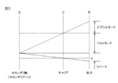
図2は、車両1の前進時および後進時におけるクラッチC1,C2およびブレーキB1の状態を示す図である。図3は、遊星歯車機構35のサンギヤ71、キャリア72およびリングギヤ73の回転数(回転速度)の関係を示す共線図である。図4は、無段変速機構33による変速比であるベルト変速比と動力分割式無段変速機4の全体での変速比であるユニット変速比、つまりインプット軸31とアウトプット軸32との回転数比であるユニット変速比との関係を示す図である。
<Speed change mode>
FIG. 2 shows the states of the clutches C1, C2 and the brake B1 when the
図2において、「○」は、クラッチC1,C2およびブレーキB1が係合状態であることを示している。「×」は、クラッチC1,C2およびブレーキB1が解放状態であることを示している。 In FIG. 2, "o" indicates that the clutches C1, C2 and the brake B1 are engaged. "X" indicates that the clutches C1, C2 and the brake B1 are released.
動力分割式無段変速機4は、車両1の前進時の変速モードとして、ベルトモードおよびスプリットモードを有している。ベルトモードとスプリットモードとは、クラッチC1が係合している状態とクラッチC2が係合している状態との切り替え(クラッチC1,C2の掛け替え)により切り替えられる。
The power split type continuously variable transmission 4 has a belt mode and a split mode as transmission modes when the
ベルトモードでは、図2に示されるように、クラッチC1およびブレーキB1が解放され、クラッチC2が係合される。これにより、スプリットドライブギヤ81がインプット軸31から切り離され、遊星歯車機構35のキャリア72がフリー(自由回転状態)になり、遊星歯車機構35のサンギヤ71とリングギヤ73とが直結される。
In belt mode, clutch C1 and brake B1 are disengaged and clutch C2 is engaged, as shown in FIG. As a result, the
インプット軸31に入力される動力は、逆転ギヤ機構34により逆転かつ減速されて、無段変速機構33のプライマリ軸41に伝達され、プライマリ軸41およびプライマリプーリ43を回転させる。プライマリプーリ43の回転は、ベルト45を介して、セカンダリプーリ44に伝達され、セカンダリプーリ44およびセカンダリ軸42を回転させる。遊星歯車機構35のサンギヤ71とリングギヤ73とが直結されているので、セカンダリ軸42と一体となって、サンギヤ71、リングギヤ73およびアウトプット軸32が回転する。したがって、ベルトモードでは、図3および図4に示されるように、ユニット変速比がベルト変速比(無段変速機構33のプライマリプーリ43とセカンダリプーリ44とのプーリ比)に前減速比(インプット軸31の回転数/プライマリ軸41の回転数)を乗じた値と一致する。
The power input to the
スプリットモードでは、図2に示されるように、クラッチC1が係合され、クラッチC2およびブレーキB1が解放される。これにより、インプット軸31とスプリットドライブギヤ81とが直結されて、インプット軸31の回転がスプリットドライブギヤ81およびスプリットドリブンギヤ82を介して遊星歯車機構35のキャリア72に伝達可能になり、遊星歯車機構35のサンギヤ71とリングギヤ73とが切り離される。
In split mode, clutch C1 is engaged and clutch C2 and brake B1 are disengaged, as shown in FIG. As a result, the
インプット軸31に入力される動力は、逆転ギヤ機構34により逆転かつ減速されて、無段変速機構33のプライマリ軸41に伝達され、プライマリ軸41からプライマリプーリ43、ベルト45およびセカンダリプーリ44を介してセカンダリ軸42に伝達され、遊星歯車機構35のサンギヤ71に伝達される。一方、インプット軸31に入力される動力は、スプリットドライブギヤ81からスプリットドリブンギヤ82を介して遊星歯車機構35のキャリア72に増速されて伝達される。
The power input to the
スプリットドライブギヤ81とスプリットドリブンギヤ82とのギヤ比(スプリット変速比)は一定で不変(固定)であるので、スプリットモードでは、インプット軸31に入力される動力が一定であれば、遊星歯車機構35のキャリア72の回転が一定速度に保持される。そのため、ベルト変速比が上げられると、遊星歯車機構35のサンギヤ71の回転数が下がるので、図3に破線で示されるように、遊星歯車機構35のリングギヤ73(アウトプット軸32)の回転数が上がる。その結果、スプリットモードでは、図4に示されるように、無段変速機構33のベルト変速比が大きいほど、動力分割式無段変速機4のユニット変速比が小さくなる。
Since the gear ratio (split gear ratio) between the
ベルトモードおよびスプリットモードにおけるアウトプット軸32の回転は、出力ギヤ37を介して、デファレンシャルギヤ5に伝達される。これにより、車両1のドライブシャフト6L,6Rが前進方向に回転する。
Rotation of the
車両1の後進時のリバースモードでは、図2に示されるように、クラッチC1,C2が解放され、ブレーキB1が係合される。これにより、スプリットドライブギヤ81がインプット軸31から切り離され、遊星歯車機構35のサンギヤ71とリングギヤ73とが切り離され、遊星歯車機構35のキャリア72が制動される。
In the reverse mode when the
インプット軸31に入力される動力は、逆転ギヤ機構34により逆転かつ減速されて、無段変速機構33のプライマリ軸41に伝達され、プライマリ軸41からプライマリプーリ43、ベルト45およびセカンダリプーリ44を介してセカンダリ軸42に伝達され、セカンダリ軸42と一体に、遊星歯車機構35のサンギヤ71を回転させる。遊星歯車機構35のキャリア72が制動されているので、サンギヤ71が回転すると、遊星歯車機構35のリングギヤ73がサンギヤ71と逆方向に回転する。このリングギヤ73の回転方向は、前進時(ベルトモードおよびスプリットモード)におけるリングギヤ73の回転方向と逆方向となる。そして、リングギヤ73と一体に、アウトプット軸32が回転する。アウトプット軸32の回転は、出力ギヤ37を介して、デファレンシャルギヤ5に伝達される。これにより、車両1のドライブシャフト6L,6Rが後進方向に回転する。
The power input to the
<車両の制御系>
図5は、本発明の一実施形態に係る制御系の構成を示す図である。
<Vehicle control system>
FIG. 5 is a diagram showing the configuration of a control system according to one embodiment of the present invention.
車両1には、マイコンを含む構成のECU(Electronic Control Unit:電子制御ユニット)が備えられている。マイコンには、たとえば、CPU、ROMおよびRAM、データフラッシュ(フラッシュメモリ)などが内蔵されている。車両1の各部を制御するため、車両1には、複数のECUが搭載されており、各ECUは、CAN(Controller Area Network)通信プロトコルによる双方向通信が可能に接続されている。複数のECUには、エンジンECU101および変速機ECU102が含まれる。
The
エンジンECU101には、アクセルセンサ111およびエンジン回転数センサ112などが接続されている。
An
アクセルセンサ111は、運転者により操作されるアクセルペダルの操作量に応じた検出信号を出力する。エンジンECU101は、アクセルセンサ111から入力される検出信号に基づいて、アクセルペダルの最大操作量に対する操作量の割合、つまりアクセルペダルが踏み込まれていないときを0%とし、アクセルペダルが最大に踏み込まれたときを100%とする百分率であるアクセル開度を演算する。
The
エンジン回転数センサ112は、エンジン2の回転(クランクシャフトの回転)に同期したパルス信号を検出信号として出力する。エンジンECU101は、エンジン回転数センサ112から入力されるパルス信号の周波数をエンジン2の回転数(エンジン回転数)に換算する。
The
エンジンECU101は、各種センサの検出信号から取得した情報および/または他のECUから入力される種々の情報などに基づいて、エンジン2の始動、停止および出力調整などのため、エンジン2に設けられた電子スロットルバルブ、インジェクタおよび点火プラグなどを制御する。
The
変速機ECU102には、プライマリ回転数センサ113およびセカンダリ回転数センサ114などが接続されている。
The
プライマリ回転数センサ113は、たとえば、動力分割式無段変速機4のプライマリ軸41またはプライマリプーリ43の回転に同期したパルス信号を検出信号として出力する。変速機ECU102は、プライマリ回転数センサ113から入力されるパルス信号の周波数をプライマリ回転数に換算する。
Primary rotation speed sensor 113 outputs, for example, a pulse signal synchronized with the rotation of
セカンダリ回転数センサ114は、たとえば、動力分割式無段変速機4のセカンダリ軸42またはセカンダリプーリ44の回転に同期したパルス信号を検出信号として出力する。変速機ECU102は、セカンダリ回転数センサ114から入力されるパルス信号の周波数をセカンダリ回転数に換算する。
Secondary
変速機ECU102は、各種センサの検出信号から取得した情報および/または他のECUから入力される種々の情報などに基づいて、動力分割式無段変速機4の変速制御などのため、動力分割式無段変速機4の各部に供給される油圧を調節するための各種のバルブなどを制御する。
The
<モード切替>
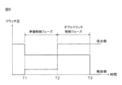
図6は、モード切替時に実施される制御について説明するためのタイミングチャートである。図7は、無段変速機構33の動力伝達状態とベルト変速比と推力比(バランス推力比)との関係を示す図である。
<Mode switching>
FIG. 6 is a timing chart for explaining the control performed when switching modes. FIG. 7 is a diagram showing the relationship between the power transmission state of the continuously
動力分割式無段変速機4のユニット変速比は、変速機ECU102によるベルト変速比の制御により変更される。ベルト変速比の制御では、まず、変速線図に基づいて、アクセル開度および車速に応じた目標回転数が設定される。変速線図は、アクセル開度および車速と目標回転数との関係を定めたマップであり、変速機ECU102のROMに格納されている。アクセル開度および車速の情報は、たとえば、エンジンECU101から変速機ECU102に入力される。目標回転数が設定されると、プライマリ軸41に入力される回転数を目標回転数に一致させる目標変速比が求められる。
The unit gear ratio of the power split type continuously variable transmission 4 is changed by control of the belt gear ratio by the
次に、目標変速比および無段変速機構33に入力される入力トルクに基づいて、無段変速機構33におけるベルト滑りを防止するのに必要なセカンダリ推力が設定される。入力トルクは、エンジントルクにトルクコンバータ3のトルク比を乗じることにより算出される。エンジントルクは、たとえば、エンジンECU101によりアクセル開度およびエンジン回転数から推定され、エンジンECU101から変速機ECU102に送信される。トルク比は、トルクコンバータ3の速度比に応じたトルク増幅率であり、その速度比は、タービン回転数をエンジン回転数で除した除算値である。
Next, the secondary thrust required to prevent belt slippage in the continuously
また、図7に示される関係(マップ)に基づいて、実変速比および入力トルクに応じた推力比(=プライマリ推力/セカンダリ推力)が設定される。そして、推力比からプライマリ推力とセカンダリ推力とが設定される。 Further, based on the relationship (map) shown in FIG. 7, a thrust ratio (=primary thrust/secondary thrust) is set according to the actual gear ratio and the input torque. Then, the primary thrust and the secondary thrust are set from the thrust ratio.
その後、その設定されたプライマリ推力およびセカンダリ推力から、プライマリプーリ43の可動シーブ52にプライマリ推力を与える油圧であるプライマリ圧およびセカンダリプーリ44の可動シーブ56にセカンダリ推力を与える油圧であるセカンダリ圧の指令値が設定され、各指令値に基づいて、目標変速比と実変速比との偏差が零に近づくように、プライマリプーリ43の油圧室54およびセカンダリプーリ44の油圧室58にそれぞれ供給される油圧が制御される。実変速比は、プライマリ回転数をセカンダリ回転数で除することにより求められる。
After that, from the set primary thrust and secondary thrust, the primary pressure, which is the hydraulic pressure that gives the primary thrust to the
ユニット変速比がスプリット変速比(スプリット点)を跨いで変更される場合、そのユニット変速比の変更には、ベルトモードとスプリットモードとの切り替え(以下、単に「モード切替」という。)が伴う。このモード切替の際には、変速機ECU102により、クラッチC1が係合している状態とクラッチC2が係合している状態とが切り替えられ、その切り替えのために、準備制御およびダブルクラッチ制御が実施される。
When the unit gear ratio is changed across the split gear ratio (split point), the change of the unit gear ratio is accompanied by switching between the belt mode and the split mode (hereinafter simply referred to as "mode switching"). At the time of this mode switching, the
ベルト変速比がスプリット変速比に向けて変更される途中、たとえば、残り一定時間が経過した時点でベルト変速比がスプリット変速比と一致するようなタイミングが到来すると、準備制御が実施される(時刻T1)。 When the belt gear ratio is being changed toward the split gear ratio, for example, when the belt gear ratio coincides with the split gear ratio after a certain amount of time has elapsed, preparatory control is performed (time T1).
ベルトモードからスプリットモードへの切り替えの際の準備制御では、クラッチC2の油圧の指令値がクラッチC2の係合状態が維持される第1油圧に応じた指令値に下げられて、クラッチC2が係合した状態のまま、クラッチC1の油圧の指令値が0から第2油圧に応じた指令値まで上げられる。第2油圧は、たとえば、クラッチC1のクラッチピストンがクラッチプレートに押圧されずに当接した状態、つまりクラッチC1がガタ詰めされた状態になるような油圧に設定されている。 In preparatory control for switching from the belt mode to the split mode, the command value for the hydraulic pressure of the clutch C2 is lowered to the command value corresponding to the first hydraulic pressure at which the engaged state of the clutch C2 is maintained, and the clutch C2 is engaged. The command value for the hydraulic pressure of the clutch C1 is increased from 0 to a command value corresponding to the second hydraulic pressure while maintaining the engaged state. The second hydraulic pressure is set, for example, to a hydraulic pressure such that the clutch piston of the clutch C1 is in contact with the clutch plate without being pressed, that is, the clutch C1 is in a tight state.
スプリットモードからベルトモードへの切り替えの際の準備制御では、クラッチC1の油圧の指令値がクラッチC1の係合状態が維持される第1油圧に応じた指令値に下げられて、クラッチC1が係合した状態のまま、クラッチC2の油圧の指令値が0から第2油圧に応じた指令値まで上げられる。第2油圧は、たとえば、クラッチC2のクラッチピストンがクラッチプレートに押圧されずに当接した状態、つまりクラッチC1がガタ詰めされた状態になるような油圧に設定されている。 In the preparatory control for switching from the split mode to the belt mode, the command value for the hydraulic pressure of the clutch C1 is lowered to the command value corresponding to the first hydraulic pressure at which the clutch C1 is kept engaged, and the clutch C1 is engaged. The command value for the hydraulic pressure of the clutch C2 is increased from 0 to a command value corresponding to the second hydraulic pressure while maintaining the engaged state. The second hydraulic pressure is set, for example, to a hydraulic pressure such that the clutch piston of the clutch C2 is in contact with the clutch plate without being pressed, that is, the clutch C1 is in a tight state.
その後、ベルト変速比がスプリット変速比と一致したことに応じて、ダブルクラッチ制御が実施される(時刻T2)。 After that, double clutch control is performed in response to the fact that the belt gear ratio matches the split gear ratio (time T2).
ベルトモードからスプリットモードへの切り替えの際のダブルクラッチ制御では、クラッチC2の油圧の指令値が第1油圧に応じた指令値に保持されて、クラッチC2が係合した状態のまま、クラッチC1の油圧の指令値が第2油圧に応じた指令値から全開圧(最大圧)に応じた指令値まで一気に上げられる。これにより、クラッチC2が係合した状態のまま、クラッチC1が完全係合し、クラッチC1,C2の両方が完全係合したダブルクラッチ状態となる。そして、ベルト変速比がスプリット変速比と一致した時点から一定時間が経過すると、クラッチC2の油圧の指令値が0に下げられて、クラッチC2が解放される(時刻T3)。 In the double clutch control when switching from the belt mode to the split mode, the command value of the hydraulic pressure of the clutch C2 is held at the command value corresponding to the first hydraulic pressure, and the clutch C1 is operated while the clutch C2 remains engaged. The command value of the hydraulic pressure is increased at once from the command value corresponding to the second hydraulic pressure to the command value corresponding to the fully open pressure (maximum pressure). As a result, the clutch C1 is fully engaged while the clutch C2 remains engaged, resulting in a double clutch state in which both the clutches C1 and C2 are fully engaged. Then, when a certain period of time has passed since the belt gear ratio coincided with the split gear ratio, the command value for the hydraulic pressure of the clutch C2 is lowered to 0, and the clutch C2 is released (time T3).
スプリットモードからベルトモードへの切り替えの際のダブルクラッチ制御では、クラッチC1の油圧の指令値が第1油圧に応じた指令値に保持されて、クラッチC1が係合した状態のまま、クラッチC2の油圧が第2油圧に応じた指令値から全開圧(最大圧)に応じた指令値まで一気に上げられる。これにより、クラッチC1が係合した状態のまま、クラッチC2が完全係合し、クラッチC1,C2の両方が完全係合したダブルクラッチ状態となる。そして、ベルト変速比がスプリット変速比と一致した時点から一定時間が経過すると、クラッチC1の油圧の指令値が0に下げられて、クラッチC1が解放される(時刻T3)。 In the double clutch control when switching from the split mode to the belt mode, the command value of the hydraulic pressure of the clutch C1 is held at the command value corresponding to the first hydraulic pressure, and the clutch C2 is operated while the clutch C1 remains engaged. The hydraulic pressure is increased at once from the command value corresponding to the second hydraulic pressure to the command value corresponding to the fully open pressure (maximum pressure). As a result, the clutch C2 is fully engaged while the clutch C1 remains engaged, resulting in a double clutch state in which both the clutches C1 and C2 are fully engaged. Then, when a certain period of time has passed since the belt gear ratio coincided with the split gear ratio, the command value for the hydraulic pressure of the clutch C1 is lowered to 0, and the clutch C1 is released (time T3).
<作用効果>
以上のように、モード切替の際には、無段変速機構33の変速比であるベルト変速比がスプリット変速比に向けて変更される。ベルト変速比がスプリット変速比に向けて変更されている間に、準備制御が実施され、係合側のクラッチC1,C2に油圧が供給される。これにより、係合側のクラッチC1,C2がガタ詰めされた状態になる。そして、ベルト変速比がスプリット変速比と一致したことに応じて、ダブルクラッチ制御が実施され、解放側のクラッチC1,C2の油圧を保持したまま、係合側のクラッチC1,C2の油圧が上げられて、係合側のクラッチC1,C2が係合する。
<Effect>
As described above, during mode switching, the belt gear ratio, which is the gear ratio of the continuously
準備制御の後、図8に示されるように、解放側のクラッチC1,C2の油圧の指令値を第1油圧に応じた指令値からスイープダウン(一定の時間変化率で漸減)させ、係合側のクラッチC1,C2の油圧の指令値を第2油圧に応じた指令値からスイープアップ(一定の時間変化率で漸増)させる制御を実施することが考えられる。しかしながら、この制御では、クラッチC1,C2の伝達トルク容量の合計がエンジントルクを上回るように指令値を設定しても、クラッチC1,C2の油圧の応答ばらつきの影響により、エンジン2の吹き上がりが生じたり、車両1の減速感が生じたりする場合がある。また、変速時間が長くなる。
After the preparatory control, as shown in FIG. 8, the command values for the hydraulic pressures of the disengaging clutches C1 and C2 are swept down (gradually decreased at a constant rate of change over time) from the command values according to the first hydraulic pressure, and engaged. It is conceivable to carry out control to sweep up (gradually increase at a constant rate of change over time) the command value of the hydraulic pressure of the clutches C1 and C2 on the side from the command value corresponding to the second hydraulic pressure. However, in this control, even if the command value is set so that the total transmission torque capacity of the clutches C1 and C2 exceeds the engine torque, the
ダブルクラッチ制御により、クラッチC1,C2の油圧の立ち上がりにばらつき(応答ばらつき)があっても、ベルト変速比がスプリット変速比と一致した状態でクラッチC1が係合している状態とクラッチC2が係合している状態とを切り替える(クラッチC1,C2を掛け替える)ことができる。そのため、ベルト変速比がスプリット変速比からずれた状態でクラッチC1が係合している状態とクラッチC2が係合している状態との切り替えが行われることを抑制でき、そのベルト変速比がスプリット変速比からずれた状態での当該切り替えによる変速ショックの発生を抑制できる。また、ダブルクラッチ制御中、クラッチC1,C2の伝達トルク容量の合計がエンジントルクをはるかに上回ることにより、クラッチC1,C2の油圧の応答ばらつきを学習しなくても、エンジン2の吹き上がりを抑制できる。
Due to the double-clutch control, even if there is variation (response variation) in the rise of the hydraulic pressures of the clutches C1 and C2, the state in which the clutch C1 is engaged and the clutch C2 is engaged with the belt gear ratio matching the split gear ratio is achieved. The engaged state can be switched (the clutches C1 and C2 are switched). Therefore, it is possible to suppress switching between the state in which the clutch C1 is engaged and the state in which the clutch C2 is engaged while the belt speed ratio is deviated from the split speed ratio. It is possible to suppress the occurrence of shift shock due to the switching in a state deviated from the gear ratio. Also, during double clutch control, the sum of the transmission torque capacities of the clutches C1 and C2 far exceeds the engine torque, so that racing of the
さらには、ダブルクラッチ制御では、係合側のクラッチC1,C2の油圧の指令値が一気に上げられるので、係合側のクラッチC1,C2の係合に要する時間を短縮でき、ひいてはクラッチC1が係合している状態とクラッチC2が係合している状態との切り替え(クラッチC1,C2の掛け替え)に要する時間(変速時間)を短縮することができる。 Furthermore, in the double clutch control, the hydraulic pressure command values for the clutches C1 and C2 on the engagement side are increased at once, so the time required for engagement of the clutches C1 and C2 on the engagement side can be shortened, and eventually the clutch C1 is engaged. It is possible to shorten the time (shift time) required for switching between the engaged state and the engaged state of the clutch C2 (replacement of the clutches C1 and C2).
また、ダブルクラッチ制御の前に準備制御が実施されて、係合側のクラッチC1,C2がガタ詰めされた状態にされるので、係合側のクラッチC1,C2の係合に要する時間を短縮でき、ひいてはクラッチC1が係合している状態とクラッチC2とが係合している状態との切り替えに要する時間、つまりモード切替に要する時間を短縮することができる。 In addition, preparatory control is performed before the double clutch control, and the clutches C1 and C2 on the engagement side are put in a tight state, so the time required for engagement of the clutches C1 and C2 on the engagement side is shortened. As a result, the time required for switching between the state in which the clutch C1 is engaged and the state in which the clutch C2 is engaged, that is, the time required for mode switching can be shortened.
<変形例>
以上、本発明の一実施形態について説明したが、本発明は、他の形態で実施することもできる。
<Modification>
Although one embodiment of the present invention has been described above, the present invention can also be implemented in other forms.
たとえば、前述の実施形態では、準備制御において、係合側のクラッチC1,C2の油圧の指令値が0から第2油圧に応じた指令値まで上げられるとしたが、図9に示されるように、係合側のクラッチC1,C2の油圧の指令値は0のままでもよい。ただし、係合側のクラッチC1,C2の油圧の指令値が0から第2油圧に応じた指令値まで上げられる構成の場合、係合側のクラッチC1,C2の係合前にガタ詰めを完了させることができるので、ダブルクラッチ制御において、係合側のクラッチC1,C2をより速やかに係合させることができる。 For example, in the above-described embodiment, the command value of the hydraulic pressure of the clutches C1 and C2 on the engagement side was raised from 0 to the command value corresponding to the second hydraulic pressure in the preparation control, but as shown in FIG. , the hydraulic pressure command values for the clutches C1 and C2 on the engagement side may remain zero. However, in the case of a configuration in which the command value of the oil pressure of the clutches C1, C2 on the engagement side is increased from 0 to the command value corresponding to the second oil pressure, the backlash elimination is completed before the clutches C1, C2 on the engagement side are engaged. Therefore, in the double clutch control, the engagement side clutches C1 and C2 can be engaged more quickly.
また、図10に示されるように、準備制御において、解放側のクラッチC1,C2の油圧の指令値が全開圧に応じた指令値に保持されて、ダブルクラッチ制御においても、解放側のクラッチC1,C2の油圧の指令値が全開圧に応じた指令値に保持されてもよい。ただし、準備制御で解放側のクラッチC1,C2の油圧の指令値が第1油圧に応じた指令値に下げられる構成では、解放側のクラッチC1,C2の油圧の指令値が0に下げられた後(時刻T3の後)の当該解放側のクラッチC1,C2の応答性が向上する。 Further, as shown in FIG. 10, in the preparatory control, the command value of the hydraulic pressure of the clutches C1 and C2 on the release side is held at the command value corresponding to the full open pressure. , C2 may be held at a command value corresponding to the fully open pressure. However, in the configuration in which the command value of the hydraulic pressure of the clutches C1 and C2 on the release side is lowered to the command value according to the first hydraulic pressure in the preparation control, the command value of the hydraulic pressure of the clutches C1 and C2 on the release side is lowered to 0. After that (after time T3), the responsiveness of the clutches C1 and C2 on the release side is improved.
さらには、図11に示されるように、準備制御において、解放側のクラッチC1,C2の油圧の指令値が第1油圧に応じた指令値に下げられ、ダブルクラッチ制御において、解放側のクラッチC1,C3の油圧の指令値が第1油圧よりも低い第3油圧に応じた指令値に下げられてもよい。また、図12に示されるように、準備制御では、解放側のクラッチC1,C2の油圧の指令値が全開圧に応じた指令値に保持され、ダブルクラッチ制御において、解放側のクラッチC1,C2の油圧の指令値が解放側のクラッチC1,C2の係合状態が維持される第3油圧に応じた指令値に下げられてもよい。これらの構成によっても、準備制御およびダブルクラッチ制御で解放側のクラッチC1,C2の油圧の指令値が全開圧に応じた指令値に保持される構成と比較して、解放側のクラッチC1,C2の油圧の指令値が0に下げられた後(時刻T3の後)の当該解放側のクラッチC1,C2の応答性を改善することができる。 Furthermore, as shown in FIG. 11, in the preparation control, the command value of the hydraulic pressures of the clutches C1 and C2 on the releasing side is lowered to the command value corresponding to the first hydraulic pressure, and in the double clutch control, the clutch C1 on the releasing side is lowered. , C3 may be lowered to a command value corresponding to a third hydraulic pressure lower than the first hydraulic pressure. Further, as shown in FIG. 12, in the preparation control, the command value of the hydraulic pressure of the clutches C1, C2 on the release side is held at a command value corresponding to the fully opened pressure, and in the double clutch control, the command value of the clutches C1, C2 on the release side may be lowered to a command value corresponding to a third hydraulic pressure at which the engaged state of the clutches C1 and C2 on the disengagement side is maintained. With these configurations as well, compared to the configuration in which the command value of the hydraulic pressure of the clutches C1 and C2 on the release side is held at the command value corresponding to the full open pressure in the preparation control and the double clutch control, the clutches C1 and C2 on the release side is lowered to 0 (after time T3), the responsiveness of the clutches C1 and C2 on the releasing side can be improved.
また、準備制御は、必須の制御ではなく、図13に示されるように、解放側のクラッチC1,C2の油圧の指令値は、ベルト変速比がスプリット変速比と一致した時点から一定時間が経過した時点(時刻T3)で、全開圧に応じた指令値から0まで一気に下げられてもよい。 In addition, the preparatory control is not an essential control. As shown in FIG. 13, the command values for the hydraulic pressures of the clutches C1 and C2 on the disengagement side are set for a certain period of time after the belt gear ratio coincides with the split gear ratio. At the point of time (time T3), the command value corresponding to the full open pressure may be lowered to 0 at once.
前述の各センサは、本発明に関連するセンサの主要なものの例示に過ぎず、エンジンECU101および変速機ECU102には、その他のセンサが接続されていてもよい。
The sensors described above are merely examples of main sensors related to the present invention, and other sensors may be connected to
エンジンECU101および変速機ECU102の機能の一部または全部は、1つのECUに集約されていてもよい。
Some or all of the functions of
また、前述の実施形態では、本発明に係る変速機の一例として、インプット軸31とアウトプット軸32との間での動力伝達経路が互いに異なるベルトモードとスプリットモードとのいずれのモードにおいても、動力が無段変速機構33を経由する構成のものを取り上げた。しかしながら、本発明は、かかる構成の変速機に限らず、無段変速機構を経由する動力伝達経路が構成されるモードと無段変速機構を経由せずにギヤ機構を経由する動力伝達経路が構成されるモードとを有する構成の変速機に適用することも可能である。
Further, in the above-described embodiment, as an example of the transmission according to the present invention, in either the belt mode or the split mode in which the power transmission paths between the
また、ギヤ機構を経由する動力伝達経路も必須ではなく、たとえば、無段変速機構を経由する動力伝達経路が構成されるモードと無段変速機構を経由せずにベルト機構などのギヤ機構以外の機構を経由する動力伝達経路が構成されるモードとを有する構成の変速機に本発明を適用することもできる。この場合のベルト機構は、変速比が固定のものであってもよいし、変速比が可変のものであってもよい。 Also, the power transmission path via the gear mechanism is not essential. The present invention can also be applied to a transmission configured to have a mode in which a power transmission path via a mechanism is configured. The belt mechanism in this case may have a fixed gear ratio or may have a variable gear ratio.
その他、前述の構成には、特許請求の範囲に記載された事項の範囲で種々の設計変更を施すことが可能である。 In addition, various design changes can be made to the above configuration within the scope of the matters described in the claims.
4:動力分割式無段変速機
31:インプット軸
32:アウトプット軸
33:無段変速機構
36:スプリット変速機構
43:プライマリプーリ
44:セカンダリプーリ
45:ベルト
102:変速機ECU(制御装置、変速制御手段、ダブルクラッチ制御手段)
C1,C2:クラッチ(第1係合要素、第2係合要素)
4: Power split type continuously variable transmission 31: Input shaft 32: Output shaft 33: Continuously variable transmission mechanism 36: Split transmission mechanism 43: Primary pulley 44: Secondary pulley 45: Belt 102: Transmission ECU (control device, transmission control means, double clutch control means)
C1, C2: Clutch (first engagement element, second engagement element)
Claims (1)
前記インプット軸と前記アウトプット軸との間で動力を伝達するモードとして、前記第1係合要素の係合および前記第2係合要素の解放により、第1モードが構成され、前記第1係合要素の解放および前記第2係合要素の係合により、前記第1モードと動力伝達経路が異なる第2モードが構成され、
前記第1モードおよび前記第2モードの少なくとも一方において、前記無段変速機構を介して動力が伝達され、前記無段変速機構の変速比が特定の値をとる場合に、前記第1モードでの変速比と前記第2モードでの変速比とが一致するように構成された変速機の制御装置であって、
前記無段変速機構の変速比を変更する変速制御手段と、
前記変速制御手段により前記無段変速機構の変速比が前記特定の値に向けて変更されている間に、係合側の前記第1係合要素または前記第2係合要素に油圧を供給する指令を出力する準備制御を実施する準備制御手段と、
前記準備制御手段による前記準備制御の実施後に、前記第1係合要素と前記第2係合要素との係合の切り替えに際して、前記第1モードでの変速比と前記第2モードでの変速比とが一致したことに応じて、解放側の前記第2係合要素または前記第1係合要素の油圧を当該解放側の前記第2係合要素または前記第1係合要素の係合が維持される油圧に保持したまま、係合側の前記第1係合要素または前記第2係合要素の油圧を当該係合側の前記第1係合要素または前記第2係合要素が完全係合する完全係合油圧に一気に上昇させる指令を出力するダブルクラッチ制御手段とを含み、
前記準備制御手段は、前記準備制御において、解放側の前記第2係合要素または前記第1係合要素の油圧を前記完全係合油圧から当該解放側の前記第2係合要素または前記第1係合要素の係合状態が維持される第1油圧に下げる指令を出力し、当該解放側の前記第2係合要素または前記第1係合要素が係合した状態のまま、係合側の前記第1係合要素または前記第2係合要素の油圧を前記完全係合油圧よりも低い第2油圧であって、当該係合側の前記第1係合要素または前記第2係合要素のクラッチピストンがクラッチプレートに押圧されずに当接した状態になる前記第2油圧に上げる指令を出力する、制御装置。 An input shaft, an output shaft, a continuously variable transmission mechanism for steplessly shifting the power input to the input shaft, and a first engagement element and a second engagement element that are engaged/released by hydraulic pressure,
As a mode for transmitting power between the input shaft and the output shaft, a first mode is configured by engaging the first engaging element and disengaging the second engaging element. A second mode having a power transmission path different from that of the first mode is configured by releasing the coupling element and engaging the second engagement element,
In at least one of the first mode and the second mode, when power is transmitted via the continuously variable transmission mechanism and the gear ratio of the continuously variable transmission mechanism takes a specific value, the transmission in the first mode A control device for a transmission configured so that the gear ratio and the gear ratio in the second mode match,
shift control means for changing the gear ratio of the continuously variable transmission mechanism;
While the gear ratio of the continuously variable transmission mechanism is changed toward the specific value by the gear shift control means, hydraulic pressure is supplied to the first engagement element or the second engagement element on the engagement side. preparation control means for performing preparation control for outputting a command;
After performing the preparation control by the preparation control means, when switching the engagement between the first engagement element and the second engagement element, the gear ratio in the first mode and the gear ratio in the second mode , the hydraulic pressure of the second engagement element or the first engagement element on the release side is maintained by the engagement of the second engagement element or the first engagement element on the release side. The hydraulic pressure of the first engagement element or the second engagement element on the engagement side is completely engaged by the first engagement element or the second engagement element on the engagement side. a double clutch control means for outputting a command to increase the full engagement oil pressure at once,
In the preparation control, the preparation control means reduces the hydraulic pressure of the second engagement element or the first engagement element on the release side from the full engagement hydraulic pressure to the second engagement element on the release side or the first engagement element on the release side. Outputting a command to lower the first hydraulic pressure that maintains the engaged state of the engaging element , and engaging the second engaging element or the first engaging element on the disengagement side in the engaged state. The hydraulic pressure of the first engagement element or the second engagement element on the engagement side is a second hydraulic pressure lower than the complete engagement hydraulic pressure, and the first engagement element or the second engagement element on the engagement side A control device that outputs a command to increase the second hydraulic pressure so that the clutch piston of the element is in contact with the clutch plate without being pressed .
Priority Applications (1)
| Application Number | Priority Date | Filing Date | Title |
|---|---|---|---|
| JP2017073308A JP7278024B2 (en) | 2017-03-31 | 2017-03-31 | gearbox controller |
Applications Claiming Priority (1)
| Application Number | Priority Date | Filing Date | Title |
|---|---|---|---|
| JP2017073308A JP7278024B2 (en) | 2017-03-31 | 2017-03-31 | gearbox controller |
Publications (2)
| Publication Number | Publication Date |
|---|---|
| JP2018173152A JP2018173152A (en) | 2018-11-08 |
| JP7278024B2 true JP7278024B2 (en) | 2023-05-19 |
Family
ID=64108381
Family Applications (1)
| Application Number | Title | Priority Date | Filing Date |
|---|---|---|---|
| JP2017073308A Active JP7278024B2 (en) | 2017-03-31 | 2017-03-31 | gearbox controller |
Country Status (1)
| Country | Link |
|---|---|
| JP (1) | JP7278024B2 (en) |
Families Citing this family (2)
| Publication number | Priority date | Publication date | Assignee | Title |
|---|---|---|---|---|
| JP7258447B2 (en) * | 2020-06-22 | 2023-04-17 | ダイハツ工業株式会社 | Control device |
| CN114763838B (en) * | 2021-01-11 | 2023-08-15 | 广州汽车集团股份有限公司 | Automobile gear shifting control method |
Citations (3)
| Publication number | Priority date | Publication date | Assignee | Title |
|---|---|---|---|---|
| JP2002139140A (en) | 2000-11-06 | 2002-05-17 | Toyota Motor Corp | Control device for transmission with continuously variable transmission |
| JP2010209943A (en) | 2009-03-06 | 2010-09-24 | Nissan Motor Co Ltd | Control apparatus for automatic transmission |
| JP2016125569A (en) | 2014-12-26 | 2016-07-11 | ダイハツ工業株式会社 | Control device for power split type continuously variable transmission |
Family Cites Families (1)
| Publication number | Priority date | Publication date | Assignee | Title |
|---|---|---|---|---|
| JP3633484B2 (en) * | 2001-01-22 | 2005-03-30 | トヨタ自動車株式会社 | Control device for vehicle having internal combustion engine and continuously variable transmission |
-
2017
- 2017-03-31 JP JP2017073308A patent/JP7278024B2/en active Active
Patent Citations (3)
| Publication number | Priority date | Publication date | Assignee | Title |
|---|---|---|---|---|
| JP2002139140A (en) | 2000-11-06 | 2002-05-17 | Toyota Motor Corp | Control device for transmission with continuously variable transmission |
| JP2010209943A (en) | 2009-03-06 | 2010-09-24 | Nissan Motor Co Ltd | Control apparatus for automatic transmission |
| JP2016125569A (en) | 2014-12-26 | 2016-07-11 | ダイハツ工業株式会社 | Control device for power split type continuously variable transmission |
Also Published As
| Publication number | Publication date |
|---|---|
| JP2018173152A (en) | 2018-11-08 |
Similar Documents
| Publication | Publication Date | Title |
|---|---|---|
| US9765886B2 (en) | Control system and control method for vehicle | |
| JP6505447B2 (en) | Control device of power split type continuously variable transmission | |
| JP7278024B2 (en) | gearbox controller | |
| JP7102076B2 (en) | Control device for continuously variable transmission | |
| JP6949432B2 (en) | Control device for continuously variable transmission | |
| JP6809969B2 (en) | Transmission control device | |
| JP7139035B2 (en) | control device for continuously variable transmission | |
| JP2013113338A (en) | Power transmission device | |
| JP6556597B2 (en) | Control device for power split type continuously variable transmission | |
| JP7191470B2 (en) | control device for continuously variable transmission | |
| JP7090979B2 (en) | Control device for continuously variable transmission | |
| JP7179414B2 (en) | vehicle controller | |
| JP7191461B2 (en) | control device for continuously variable transmission | |
| JP7242125B2 (en) | vehicle controller | |
| JP6809967B2 (en) | Transmission control device | |
| JP7123473B2 (en) | Control device for power split type continuously variable transmission | |
| JP6809968B2 (en) | Transmission control device | |
| JP7109858B2 (en) | gearbox controller | |
| JP7765426B2 (en) | Transmission control device | |
| JP7013088B2 (en) | Control device for continuously variable transmission | |
| JP7258447B2 (en) | Control device | |
| JP7139058B2 (en) | control device for continuously variable transmission | |
| JP7511972B2 (en) | Vehicle control device | |
| JP6968502B2 (en) | Control device for continuously variable transmission | |
| JP6884483B2 (en) | Vehicle control device |
Legal Events
| Date | Code | Title | Description |
|---|---|---|---|
| A621 | Written request for application examination |
Free format text: JAPANESE INTERMEDIATE CODE: A621 Effective date: 20200226 |
|
| A977 | Report on retrieval |
Free format text: JAPANESE INTERMEDIATE CODE: A971007 Effective date: 20201126 |
|
| A131 | Notification of reasons for refusal |
Free format text: JAPANESE INTERMEDIATE CODE: A131 Effective date: 20201222 |
|
| A521 | Request for written amendment filed |
Free format text: JAPANESE INTERMEDIATE CODE: A523 Effective date: 20210222 |
|
| A02 | Decision of refusal |
Free format text: JAPANESE INTERMEDIATE CODE: A02 Effective date: 20210713 |
|
| A521 | Request for written amendment filed |
Free format text: JAPANESE INTERMEDIATE CODE: A523 Effective date: 20211012 |
|
| C60 | Trial request (containing other claim documents, opposition documents) |
Free format text: JAPANESE INTERMEDIATE CODE: C60 Effective date: 20211012 |
|
| A911 | Transfer to examiner for re-examination before appeal (zenchi) |
Free format text: JAPANESE INTERMEDIATE CODE: A911 Effective date: 20211021 |
|
| C21 | Notice of transfer of a case for reconsideration by examiners before appeal proceedings |
Free format text: JAPANESE INTERMEDIATE CODE: C21 Effective date: 20211026 |
|
| A912 | Re-examination (zenchi) completed and case transferred to appeal board |
Free format text: JAPANESE INTERMEDIATE CODE: A912 Effective date: 20211210 |
|
| C211 | Notice of termination of reconsideration by examiners before appeal proceedings |
Free format text: JAPANESE INTERMEDIATE CODE: C211 Effective date: 20211214 |
|
| C22 | Notice of designation (change) of administrative judge |
Free format text: JAPANESE INTERMEDIATE CODE: C22 Effective date: 20220315 |
|
| C22 | Notice of designation (change) of administrative judge |
Free format text: JAPANESE INTERMEDIATE CODE: C22 Effective date: 20220419 |
|
| C13 | Notice of reasons for refusal |
Free format text: JAPANESE INTERMEDIATE CODE: C13 Effective date: 20220517 |
|
| A521 | Request for written amendment filed |
Free format text: JAPANESE INTERMEDIATE CODE: A523 Effective date: 20220714 |
|
| C22 | Notice of designation (change) of administrative judge |
Free format text: JAPANESE INTERMEDIATE CODE: C22 Effective date: 20221011 |
|
| C13 | Notice of reasons for refusal |
Free format text: JAPANESE INTERMEDIATE CODE: C13 Effective date: 20221025 |
|
| A521 | Request for written amendment filed |
Free format text: JAPANESE INTERMEDIATE CODE: A523 Effective date: 20221226 |
|
| C23 | Notice of termination of proceedings |
Free format text: JAPANESE INTERMEDIATE CODE: C23 Effective date: 20230404 |
|
| A61 | First payment of annual fees (during grant procedure) |
Free format text: JAPANESE INTERMEDIATE CODE: A61 Effective date: 20230509 |
|
| R150 | Certificate of patent or registration of utility model |
Ref document number: 7278024 Country of ref document: JP Free format text: JAPANESE INTERMEDIATE CODE: R150 |
|
| R250 | Receipt of annual fees |
Free format text: JAPANESE INTERMEDIATE CODE: R250 |