JP7304246B2 - vehicle controller - Google Patents
vehicle controller Download PDFInfo
- Publication number
- JP7304246B2 JP7304246B2 JP2019164183A JP2019164183A JP7304246B2 JP 7304246 B2 JP7304246 B2 JP 7304246B2 JP 2019164183 A JP2019164183 A JP 2019164183A JP 2019164183 A JP2019164183 A JP 2019164183A JP 7304246 B2 JP7304246 B2 JP 7304246B2
- Authority
- JP
- Japan
- Prior art keywords
- wheel
- turning
- vehicle
- state
- steering
- Prior art date
- Legal status (The legal status is an assumption and is not a legal conclusion. Google has not performed a legal analysis and makes no representation as to the accuracy of the status listed.)
- Active
Links
Images




Landscapes
- Steering-Linkage Mechanisms And Four-Wheel Steering (AREA)
- Body Structure For Vehicles (AREA)
- Steering Control In Accordance With Driving Conditions (AREA)
- Control Of Driving Devices And Active Controlling Of Vehicle (AREA)
- Retarders (AREA)
Description
本発明は、自動車等の車両の旋回状態を制御する車両制御装置に関する。 The present invention relates to a vehicle control device that controls the turning state of a vehicle such as an automobile.
四輪の乗用車等の自動車は、通常ドライバからの操舵操作等に応じて、前二輪の舵角を変化(ステア)させることにより、タイヤにスリップアングルを発生させ、タイヤが発生する横力(コーナリングフォース)から得られるヨーモーメントにより車両を旋回させる。
また、旋回開始時における応答性や、定常旋回時における安定性を向上するため、後輪を前輪と逆相又は同相に操舵する各種の四輪操舵機構が提案されている。
Automobiles, such as four-wheeled passenger cars, usually change the steering angle of the front two wheels in response to the driver's steering operation, etc., to generate a slip angle in the tires, and the lateral force generated by the tires (cornering). The vehicle is turned by the yaw moment obtained from the force).
In addition, various four-wheel steering mechanisms have been proposed in which the rear wheels are steered in the opposite phase or in the same phase as the front wheels in order to improve responsiveness at the start of turning and stability during steady turning.
さらに、近年では左右の車輪の舵角を独立して制御可能な操舵機構が提案されている。
車両の左右独立操舵に関する従来技術として、例えば特許文献1には、ジャッキアップ現象による車体ロール時の車体上方移動を抑制するため、車体がロールしていることが検出された場合に、全輪独立操舵制御手段を用いて左右前輪又は左右後輪の少なくとも一方をトーアウト側へステアすることが記載されている。
特許文献2には、左右の前後輪の舵角を独立して制御可能なステアバイワイヤ式の4輪操舵装置を有する車両において、通常時には操舵操作に応じて前後輪を同相にステアするとともに、左右輪が接する路面の摩擦係数が異なった状態での加減速時に、左右の舵角を独立して制御することが記載されている。
Furthermore, in recent years, a steering mechanism capable of independently controlling the steering angles of the left and right wheels has been proposed.
As a prior art related to left and right independent steering of a vehicle, for example,
エンジン、モータ等の走行用動力源の出力を左右車輪に伝達する動力伝達機構には、例えば旋回時の左右車輪の回転速度差を許容する差動機構(ディファレンシャル)が設けられている。
また、このような差動機構に、限界走行時の駆動力(トラクション)向上のため、左右車輪の動力伝達機構を相互に拘束して差動を制限する差動制限機構(リミテッドスリップディファレンシャル、LSD)を設けることが知られている。
しかし、このような差動制限機構は、原理的に回転速度が高速である側から低速である側へトルクが移動する性質(トルクバイアス)を有するため、タイヤのスリップ率が比較的小さい通常の旋回時には、回転速度が遅い旋回内輪側の駆動力が旋回外輪側の駆動力よりも大きくなる傾向がある。このような駆動力差は、車両の旋回方向とは逆方向へのヨーモーメントを発生させることから、車両の運動性が低下(アンダーステア傾向が促進)されてしまう。
上述した問題に鑑み、本発明の課題は、差動制限機構を有する車両の運動性を向上した車両制御装置を提供することである。
A power transmission mechanism that transmits the output of a driving power source such as an engine or a motor to left and right wheels is provided with a differential mechanism that allows a difference in rotational speed between the left and right wheels during turning, for example.
In addition, in order to improve the driving force (traction) during limit driving, a differential limiting mechanism (Limited Slip Differential, LSD) that restricts the differential by mutually restraining the power transmission mechanism of the left and right wheels is added to such a differential mechanism. ) is known to be provided.
However, in principle, such a differential limiting mechanism has the property (torque bias) that the torque is transferred from the side where the rotation speed is high to the side where the rotation speed is low. When turning, the driving force on the side of the inner wheel, which rotates slowly, tends to be greater than the driving force on the side of the outer wheel. Such a difference in driving force generates a yaw moment in the direction opposite to the turning direction of the vehicle, which reduces the maneuverability of the vehicle (promotes understeer tendency).
SUMMARY OF THE INVENTION In view of the problems described above, an object of the present invention is to provide a vehicle control device that improves the maneuverability of a vehicle having a differential limiting mechanism.
本発明は、以下のような解決手段により、上述した課題を解決する。
請求項1に係る発明は、右側車輪及び左側車輪に駆動力を伝達するとともに前記右側車輪と前記左側車輪との差動を許容する差動機構と、前記差動機構に設けられ前記差動を制限する差動制限機構と、前記右側車輪及び前記左側車輪のトーとキャンバとの少なくとも一方をアクチュエータにより左右独立して変化させる車輪変位機構と、車両の旋回状態を検出する旋回状態検出部と、前記右側車輪と前記左側車輪のスリップ状態を検出するスリップ状態検出部と、車両が旋回状態であり、所定以上の駆動力が前記差動機構に伝達されており、かつ前記右側車輪と前記左側車輪とのうち旋回内輪にスリップ状態が発生していない場合に、前記旋回内輪の前記トーと前記キャンバとの少なくとも一方を変位させて前記旋回内輪のスリップ率を増加させる制御部と、を備えることを特徴とする車両制御装置である。
これによれば、旋回内輪のトー、キャンバの少なくとも一方を変位させてタイヤ作用力が摩擦円限界を超過する状態とし、スリップ率が増加したスリップ状態とすることにより、差動制限機構が旋回内輪側から旋回外輪側へトルクを移動させて旋回外輪の駆動力が旋回内輪の駆動力よりも大きい状態とすることができる。
これにより、左右車輪の駆動力差が車両の旋回を促進する方向のヨーモーメントを発生するため、車両の旋回性能を向上することができる。
The present invention solves the problems described above by means of the following solutions.
The invention according to
According to this, at least one of the toe and camber of the turning inner wheel is displaced so that the tire acting force exceeds the friction circle limit, and the slip state with an increased slip ratio is achieved, thereby causing the differential limiting mechanism to operate as the turning inner wheel. The driving force of the turning outer wheel can be made larger than the driving force of the turning inner wheel by moving the torque from the side to the turning outer wheel side.
As a result, the driving force difference between the left and right wheels generates a yaw moment in a direction that promotes turning of the vehicle, so that the turning performance of the vehicle can be improved.
請求項2に係る発明は、前記車輪変位機構は、前記右側車輪と前記左側車輪との舵角を左右独立して変化させる機構であり、前記制御部は、前記旋回内輪をトーアウト側にステアすることによって前記旋回内輪のスリップ率を増加させることを特徴とする請求項1に記載の車両制御装置である。
これによれば、いわゆる4輪操舵機能を有する車両の後輪操舵機構を利用し、比較的汎用性のあるデバイスを利用して本発明を実車に容易に適用することができる。
In the invention according to
According to this, the present invention can be easily applied to an actual vehicle by using a rear wheel steering mechanism of a vehicle having a so-called four-wheel steering function and using a relatively versatile device.
請求項3に係る発明は、前記制御部は、前記旋回内輪のトーアウト側へのステア量を、前記旋回内輪のスリップ率が所定値以上となるよう設定することを特徴とする請求項2に記載の車両制御装置である。
これによれば、旋回内輪を確実にスリップ状態に移行させて上述した効果を確実に得ることができる。
The invention according to
According to this, it is possible to reliably shift the turning inner wheel to the slip state and to reliably obtain the above-described effects.
請求項4に係る発明は、ドライバの操舵操作量を検出する操舵操作量検出部と、ドライバの要求トルクを検出する要求トルク検出部とを有し、前記制御部は、前記操舵操作量及び前記要求トルクがそれぞれ所定の閾値以上である場合にのみ前記旋回内輪のスリップ率を増加させる制御を行うことを特徴とする請求項1から請求項3までのいずれか1項に記載の車両制御装置である。
これによれば、ドライバが駆動トルクによりヨーモーメントを利用して旋回性能を向上させたいと意図する場合に、ドライバの意図に忠実な車両の制御を行うことができる。
The invention according to
According to this, when the driver intends to improve the turning performance by utilizing the yaw moment from the driving torque, the vehicle can be controlled faithfully to the driver's intention.
請求項5に係る発明は、車両の目標となる旋回状態を算出する目標旋回状態算出部と、車両の実際の旋回状態を検出する旋回状態検出部とを有し、前記制御部は、前記目標となる旋回状態と前記実際の旋回状態との差分が所定値以上である場合に前記旋回内輪のスリップ率を増加させる制御を行うことを特徴とする請求項1から請求項3までのいずれか1項に記載の車両制御装置である。
これによれば、実際の旋回状態が目標となる旋回状態から乖離した場合に旋回内輪をスリップ状態とする制御を行うことにより、車両の実際の旋回状態を目標とする旋回状態に近付け、ライントレース性に優れた良好な操縦安定性を得ることができる。
The invention according to claim 5 has a target turning state calculation section for calculating a target turning state of the vehicle, and a turning state detection section for detecting an actual turning state of the vehicle, and the control section controls the target turning state. 4. Any one of
According to this, when the actual turning state deviates from the target turning state, control is performed so that the turning inner wheel is put in the slip state, thereby bringing the actual turning state of the vehicle closer to the target turning state and line tracing. It is possible to obtain good steering stability with excellent performance.
以上説明したように、本発明によれば、差動制限機構を有する車両の運動性を向上した車両制御装置を提供することができる。 As described above, according to the present invention, it is possible to provide a vehicle control device having a differential limiting mechanism and improving the maneuverability of the vehicle.
<第1実施形態>
以下、本発明を適用した車両制御装置の第1実施形態について説明する。
第1実施形態の車両制御装置は、例えば、乗用車等の自動車に搭載されるものである。
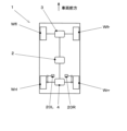
図1は、第1実施形態の車両制御装置を有する車両の駆動系の構成を模式的に示す図である。
<First Embodiment>
A first embodiment of a vehicle control device to which the present invention is applied will be described below.
A vehicle control device according to the first embodiment is mounted in an automobile such as a passenger car, for example.
FIG. 1 is a diagram schematically showing the configuration of a drive system of a vehicle having a vehicle control device according to the first embodiment.
図1に示すように、車両1は、左前輪Wfl、右前輪Wfr、左後輪Wrl、右後輪Wrrを有する4輪の乗用車である。
左前輪Wfl、右前輪Wfrは、周知の電動パワーステアリング装置を有する操舵装置により、ドライバからの操舵操作、あるいは、自動運転装置、運転支援装置からの操舵指令値に応じて、左右連動してステアされる。
左後輪Wrl、右後輪Wrrは、左右独立した後輪操舵機構により、独立してステア可能となっている。
この点に関しては、後に詳しく説明する。
As shown in FIG. 1, the
The front left wheel Wfl and the front right wheel Wfr are steered in conjunction with each other by a steering device having a well-known electric power steering device according to a steering operation from a driver or a steering command value from an automatic driving device or a driving support device. be done.
The left rear wheel Wrl and the right rear wheel Wrr can be steered independently by left and right independent rear wheel steering mechanisms.
This point will be described in detail later.
車両1は、センターディファレンシャル2、フロントディファレンシャル3、リアディファレンシャル4を備えている。
センターディファレンシャル2は、例えばエンジン、モータジェネレータ等の走行用動力源が発生する出力を、フロントディファレンシャル3、リアディファレンシャル4に伝達する動力伝達機構である。
センターディファレンシャル2は、フロントディファレンシャル3、リアディファレンシャル4の回転速度差を許容する差動機構を備えている。
また、この差動機構は、回転速度差を規制する差動制限機構(リミテッドスリップディファレンシャル:LSD)を有する。
差動制限機構として、例えば、前輪側の出力部と後輪側の出力部とを相互に拘束する締結状態と、拘束を解除した開放状態とを切換可能であるとともに、締結状態における締結力を制御可能な油圧式あるいは電磁式などの湿式多板クラッチ(トランスファクラッチ141)を用いることができる。
A
The
The
This differential mechanism also has a differential limiting mechanism (limited slip differential: LSD) that regulates the rotational speed difference.
As a differential limiting mechanism, for example, it is possible to switch between a fastened state in which the front wheel side output section and the rear wheel side output section are mutually restrained and an open state in which the restraint is released, and the fastening force in the fastened state is reduced. A controllable hydraulic or electromagnetic wet multi-plate clutch (transfer clutch 141) can be used.
フロントディファレンシャル3は、センターディファレンシャル2から伝達される動力を、ドライブシャフトを介して左前輪Wfl、右前輪Wfrに伝達する動力伝達機構である。
フロントディファレンシャル3は、左前輪Wfl、右前輪Wfrの回転速度差(差動)を許容する差動機構を備えている。
The
The
リアディファレンシャル4は、センターディファレンシャル2から伝達される動力を、ドライブシャフトを介して左後輪Wrl、右後輪Wrrに伝達する動力伝達機構である。
リアディファレンシャル4は、左後輪Wrl、右後輪Wrrの回転速度差(差動)を許容する差動機構を備えている。
The
The
フロントディファレンシャル3、リアディファレンシャル4の差動機構は、例えば左右一方の車輪のスリップ時等に、左右車輪の回転速度差を規制する差動制限機構(LSD)を有する。
これらの差動制限機構として、例えば、左右車輪の回転速度差に応じて多板クラッチのクラッチプレートを押圧するカム機構を有する機械式LSDを用いることができる。
機械式LSDは、左右車輪の一方がスリップ状態となったときに、多板クラッチを締結して左右車輪の回転速度差を制限する。
また、LSDは、回転速度が速い側の車輪から、回転速度が遅い側の車輪へトルクを移動(トルクバイアス)させる特性を有する。例えば、旋回時に旋回内輪にスリップが生じた場合(タイヤのスリップ率が通常の旋回時よりも高い状態である場合)には、旋回内輪側から旋回外輪側へのトルクの移動が生じ、旋回外輪側の駆動力が旋回内輪側よりも大きくなる。
なお、スリップ率は、車体速度と車輪速度(周速)との差分を、車体速度で除することによって得られる値である。
The differential mechanism of the
As these differential limiting mechanisms, for example, a mechanical LSD having a cam mechanism that presses the clutch plates of the multi-disc clutch according to the rotational speed difference between the left and right wheels can be used.
A mechanical LSD engages a multi-plate clutch to limit the rotational speed difference between the left and right wheels when one of the left and right wheels slips.
In addition, the LSD has the characteristic of transferring torque (torque bias) from the wheel on the side of faster rotation speed to the wheel on the side of slower rotation speed. For example, when the inner wheel slips during turning (when the slip rate of the tire is higher than during normal turning), torque is transferred from the inner wheel side to the outer wheel side, causing the outer wheel to move. The driving force on the side becomes larger than that on the turning inner wheel side.
The slip ratio is a value obtained by dividing the difference between the vehicle speed and the wheel speed (peripheral speed) by the vehicle speed.
次に、上述した後輪操舵機構の構成について説明する。
図2は、第1実施形態の車両におけるリアサスペンションの外観斜視図である。
図2は、左後輪のサスペンション装置を、斜め前方側かつ斜め上方側から見た状態を示している。
サスペンション装置10は、リアサブフレーム11、ハウジング12、ロワアーム13、アッパアーム14、トレーリングアーム15、トーコントロールアーム16、ダンパスプリングユニット17、スタビライザ18、アクチュエータ20等を備えて構成されている。
Next, the configuration of the rear wheel steering mechanism described above will be described.
FIG. 2 is an external perspective view of the rear suspension in the vehicle of the first embodiment.
FIG. 2 shows a state in which the suspension device for the left rear wheel is seen obliquely from the front side and from the obliquely upper side.
The
リアサブフレーム11は、図示しない車体の後部床下に取り付けられる構造部材である。
リアサブフレーム11には、各アーム類の車体側支点が設けられる。
リアサブフレーム11は、例えば、上方から見た平面視においてほぼ矩形状(井桁状)に形成され、前方左右、後方左右の4か所において、弾性体ブッシュを介して車体に締結されている。
The
The
The
ハウジング12は、左後輪Wrlが締結される図示しないハブを回転可能に支持する図示しないハブベアリングが収容される部材である。
サスペンション装置10は、ハウジング12を車体及びリアサブフレーム11に対して、所定の軌跡に沿ってストローク可能に支持する機能を有する。
The
The
ロワアーム13は、平面視において車幅方向にほぼ沿って配置され、ハウジング12の下部と、リアサブフレーム11との間にわたして設けられたリンク状の部材である。
アッパアーム14は、平面視において車幅方向にほぼ沿いかつロワアーム13の上方側に設けられ、ハウジング12の上部と、リアサブフレーム11との間にわたして設けられたリンク状の部材である。
ロワアーム13、アッパアーム14は、ハウジング12の主に車幅方向における位置決めを行うとともに、ストローク時における左後輪Wrlのキャンバ変化をコントロールする機能を有する。
The
The
The
トレーリングアーム15は、平面視において車両前後方向にほぼ沿って配置され、ハウジング12の下部と、リアサブフレーム11との間にわたして設けられたリンク状の部材である。
トレーリングアーム15は、ハウジング12の主に車両前後方向における位置決めを行うとともに、ストローク時における左後輪Wrlを車幅方向から見たときの軌跡をコントロールする機能を有する。
The trailing
The trailing
トーコントロールアーム16は、平面視において車幅方向にほぼ沿って配置され、ハウジング12の前部と、リアサブフレーム11との間にわたして設けられたリンク状の部材である。
トーコントロールアーム16は、ハウジング12の主にトー角(鉛直軸回りにおける角度位置)をコントロールする機能を有する。
The
The
上述した各アームの両端部は、例えば弾性体ブッシュやボールジョイント(スフェリカルベアリング)を介して、リアサブフレーム11又はハウジング12に対して揺動可能に連結されている。
Both ends of each arm described above are pivotably connected to the
ダンパスプリングユニット17は、ダンパとコイルスプリングとをユニット化したものである。
ダンパ(ショックアブソーバ)は、サスペンション装置10のストローク速度に応じた減衰力を発生する減衰要素である。
コイルスプリングは、ダンパの外径側にダンパと同心に設けられ、サスペンション装置10のストローク量に応じたばね反力を発生する。
ダンパスプリングユニット17の下端部は、ロワアーム13のハウジング12側の端部近傍に揺動可能に連結されている。
ダンパスプリングユニット17の上端部は、車体側に設けられた図示しないマウント部に締結される。
The
A damper (shock absorber) is a damping element that generates a damping force according to the stroke speed of the
The coil spring is provided concentrically with the damper on the outer diameter side of the damper, and generates a spring reaction force according to the stroke amount of the
A lower end portion of the
An upper end portion of the
スタビライザ18は、サスペンション装置10のストロークに左右差が発生した場合に、これを低減する方向への反力を発生して車体のロールを抑制するものである。
スタビライザ18は、ばね鋼からなる棒材により形成されたトーションバースプリングであるスタビライザバーの両端部を、左右のロワアーム13に図示しないリンクを介して連結して構成されている。
The
The
トーコントロールアーム16の中間部には、トーコントロールアーム16の全長を伸縮させるアクチュエータ20が設けられている。
アクチュエータ20は、例えば、ボールねじ機構及びこれを駆動する電動モータ等を有する構成とすることができる。
アクチュエータ20は、後述する後輪操舵制御ユニット150からの指令に応じて伸縮する。
アクチュエータ20は、左後輪Wrl、右後輪Wrrのトー角を左右独立して変位させることが可能な車輪変位機構である。
なお、以下の説明において、左右のサスペンション装置10にそれぞれ設けられたアクチュエータ20に、添字L,Rをそれぞれ付して説明する。
An
The
The
In the following description, the
次に、上述したアクチュエータ20(20L,20R)を制御する制御システムの構成について説明する。
図3は、第1実施形態の車両制御装置における制御システムの構成を模式的に示すブロック図である。
第1実施形態の車両制御装置100は、車両運動制御ユニット110、パワーステアリング制御ユニット120、エンジン制御ユニット130、トランスミッション制御ユニット140、後輪操舵制御ユニット150等を有する。
これらの各ユニットは、例えば、CPU等の情報処理部、RAMやROMなどの記憶部、入出力インターフェイス及びこれらを接続するバス等を有する。
また、各ユニットは、例えばCAN通信システムなどの車載LANシステムを介して、相互に通信可能となっている。
Next, the configuration of the control system that controls the actuators 20 (20L, 20R) described above will be described.
FIG. 3 is a block diagram schematically showing the configuration of the control system in the vehicle control device of the first embodiment.
The
Each of these units has, for example, an information processing section such as a CPU, a storage section such as a RAM and a ROM, an input/output interface, and a bus connecting these.
Also, each unit can communicate with each other via an in-vehicle LAN system such as a CAN communication system.
車両運動制御ユニット110は、各ユニット及びセンサ類からの入力に基づいて車両の旋回状態を把握し、その結果に基づいて、後輪操舵制御ユニット150への指令値を決定するものである。
車両制御ユニット110は、パワーステアリング制御ユニット120から、前輪を操舵する操舵装置の現在の舵角(ドライバの操舵操作量)に関する情報を取得する。
また、車両制御ユニット110は、エンジン制御ユニット130から、アクセル開度(ドライバのアクセルペダル操作量)に関する情報を取得する。
The vehicle
The
The
車両制御ユニット110には、ヨーレートセンサ111、横Gセンサ112、車輪速センサ113が接続されている。
ヨーレートセンサ111は、車体の鉛直軸回りの回転角速度(ヨーレート)を検出するものである。
横Gセンサ112は、車体に車幅方向に作用する加速度を検出するものである。
ヨーレートセンサ111、横Gセンサ112は、後述する舵角センサ121と協働して車両の旋回状態を検出する旋回状態検出部として機能する。
車輪速センサ113は、各車輪の回転速度を個別に検出するものである。
車輪速センサ113が検出する各車輪の回転速度を比較することにより、特定の車輪のスリップ率を推定することが可能である。
車輪速センサ113は、スリップ状態検出部としての機能を有する。
A
The
The
The
The
By comparing the rotation speed of each wheel detected by the
The
パワーステアリング制御ユニット120は、左前輪Wfl、右前輪Wfrを操舵する操舵機構に設けられる電動パワーステアリング装置を統括的に制御するものである。
パワーステアリング制御ユニット120には、舵角センサ121が接続されている。
舵角センサ121は、ドライバが操舵操作を入力するステアリングホイールが接続されたステアリングシャフトの回転角度を検出する角度エンコーダを有する。
舵角センサ121が検出する舵角は、ドライバからの操舵操作量とほぼ一致する。
The power
A
The
The steering angle detected by the
エンジン制御ユニット130は、車両の走行用動力源であるエンジン及びその補機類を統括的に制御するものである。
エンジン制御ユニット130には、アクセル開度センサ131が接続されている。
アクセル開度センサ131は、ドライバが加速要求を入力する図示しないアクセルペダルの操作量(踏込み量)を検出するものである。
エンジン制御ユニット130は、アクセル開度センサ131の出力等に基づいてドライバ要求トルクを設定し、エンジンが実際に発生する実トルクがドライバ要求トルクと一致するよう、エンジンの出力調整を行う。
The
An
The
The
トランスミッション制御ユニット140は、エンジンの出力回転を変速してセンターディファレンシャル2に伝達する変速機及びその補機類を統括的に制御するものである。
変速機として、例えばチェーン式の無段変速機を用いることができる。
また、トランスミッション制御ユニット140は、センターディファレンシャル2に設けられるトランスファクラッチ141の締結力(拘束力)を制御する機能を有する。
The
For example, a chain-type continuously variable transmission can be used as the transmission.
The
後輪操舵制御ユニット150は、車両運動制御ユニット110からの指令に応じて、左後輪Wrl、右後輪Wrrをそれぞれ転舵する左側アクチュエータ20L、右側アクチュエータ20Rを駆動させるものである。
The rear wheel
第1実施形態のように、フロントディファレンシャル3、リアディファレンシャル4に差動制限機構を有する車両においては、以下説明するように、差動制限機構による左右車輪間のトルクの移動により、旋回性能に影響が発生する場合がある。
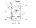
図4は、差動制限機構を有する車両の旋回時のタイヤ横力、タイヤ駆動力、車体のヨーモーメントの状態を模式的に示す図であって、旋回内輪がスリップ状態ではない状態を示している。
通常の旋回状態においては、旋回外輪のほうが旋回内輪よりも走行距離が大きくなることから、差動制限機構が拘束された場合、旋回外輪側から旋回内輪側へのトルクの移動が発生する。
このため、図4に示す左旋回状態においては、左前輪Wflの駆動力Tflは、右前輪Wfrの駆動力Tfrよりも大きくなり、左後輪Wrlの駆動力Trlは、右後輪Wrrの駆動力Trrよりも大きくなる。
車両は左旋回により図4においては反時計回りにヨー運動をすることになるが、このような左右車輪の駆動力差は、旋回を妨げる時計回りのヨーモーメントを発生させてしまい、これにより車両の旋回性能が損なわれてしまう。
図4において、操舵により発生する前輪のスリップアングルにより発生するヨーをYst、前輪の左右駆動力差により発生するヨーをYft、後輪の左右駆動力差により発生するヨーをYrtとして図示する。
また、車体に作用する横G(遠心力)をGy、前輪、後輪のタイヤ発生横力をLFf、LFrとして図示する。
In a vehicle having a differential limiting mechanism in the
FIG. 4 is a diagram schematically showing the states of the tire lateral force, the tire driving force, and the yaw moment of the vehicle body during turning of a vehicle having a differential limiting mechanism, and shows a state in which the inner wheels of the turn are not in a slipping state. there is
In a normal turning state, the traveling distance of the outer turning wheel is longer than that of the inner turning wheel. Therefore, when the differential limiting mechanism is restrained, torque is transferred from the turning outer wheel side to the turning inner wheel side.
Therefore, in the left turning state shown in FIG. 4, the driving force Tfl of the left front wheel Wfl becomes larger than the driving force Tfr of the right front wheel Wfr, and the driving force Trl of the left rear wheel Wrl becomes the driving force of the right rear wheel Wrr. larger than the force Trr.
When the vehicle turns to the left, the vehicle yaws counterclockwise in FIG. turning performance is impaired.
In FIG. 4, Yst is the yaw generated by the slip angle of the front wheels generated by steering, Yft is the yaw generated by the difference between the left and right driving forces of the front wheels, and Yrt is the yaw generated by the difference between the left and right driving forces of the rear wheels.
Further, the lateral G (centrifugal force) acting on the vehicle body is represented by Gy, and the lateral forces generated by the tires of the front and rear wheels are represented by LFf and LFr.
図5は、差動制限機構を有する車両の旋回時のタイヤ横力、タイヤ駆動力、車体のヨーモーメントの状態を模式的に示す図であって、旋回内輪がスリップ状態である状態を示している。
旋回内輪である左前輪Wfl、右前輪Wfrが、通常よりもスリップ率が大きいスリップ状態となり、その回転速度が旋回外輪である右前輪Wfr,右後輪Wrrの回転速度を上回ると、フロントディファレンシャル3、リアディファレンシャル4の差動制限機構は、旋回内輪側から旋回外輪側へトルクを移動させる。
このため、図5に示す左旋回状態においては、右前輪Wfrの駆動力Tfrは、左前輪Wflの駆動力Tflよりも大きくなり、右後輪Wrrの駆動力Trrは、右後輪Wrrの駆動力Trrよりも大きくなる。
この場合、左右車輪の駆動力差は、いわゆるトルクベクタリングによる回頭性向上制御と同様に、旋回を促進する反時計回りのヨーモーメントを発生させ、これにより車両の旋回性能が向上する。
このような状態での旋回を、本明細書において、「トルク旋回」と称する。
FIG. 5 is a diagram schematically showing the states of the tire lateral force, the tire driving force, and the yaw moment of the vehicle body during turning of a vehicle having a differential limiting mechanism, and shows a state in which the inner wheel of the turn is in a slipping state. there is
When the front left wheel Wfl and the front right wheel Wfr, which are turning inner wheels, enter a slip state with a slip rate larger than normal, and their rotational speeds exceed the rotational speeds of the right front wheel Wfr and right rear wheel Wrr, which are turning outer wheels, the
Therefore, in the left turning state shown in FIG. 5, the driving force Tfr of the right front wheel Wfr becomes larger than the driving force Tfl of the left front wheel Wfl, and the driving force Trr of the right rear wheel Wrr becomes the driving force of the right rear wheel Wrr. larger than the force Trr.
In this case, the driving force difference between the left and right wheels generates a counterclockwise yaw moment that promotes turning, similar to the turning performance improvement control by so-called torque vectoring, thereby improving the turning performance of the vehicle.
A turn in such a state is referred to herein as a "torque turn".
第1実施形態の車両制御装置においては、旋回内輪側の後輪をトーアウト側に操舵してタイヤの摩擦円限界を超えさせることにより、当該車輪をスリップ状態として、車両をトルク旋回状態に移行させ、旋回性能を向上するトルク旋回制御を実行する。
図6は、第1実施形態の車両制御装置における旋回時のトルク旋回制御を示すフローチャートである。
以下、ステップ毎に順を追って説明する。
In the vehicle control system of the first embodiment, the rear wheel on the inside wheel side of the turn is steered toe-out to exceed the friction circle limit of the tire, thereby putting the wheel in the slip state and shifting the vehicle to the torque turning state. , torque turning control is executed to improve turning performance.
FIG. 6 is a flowchart showing torque turning control during turning in the vehicle control system of the first embodiment.
Each step will be described in order below.
<ステップS01:舵角センサ出力検出>
車両運動制御ユニット110は、ステアリング制御ユニット120を介して舵角センサ121が検出した舵角に関する情報を取得する。
その後、ステップS02に進む。
<Step S01: Detection of steering angle sensor output>
The vehicle
After that, the process proceeds to step S02.
<ステップS02:アクセル開度センサ出力検出>
車両運動制御ユニット110は、エンジン制御ユニット130を介して、アクセル開度センサ131が検出したアクセル開度を取得する。
その後、ステップS03に進む。
<Step S02: Detection of accelerator opening sensor output>
The vehicle
After that, the process proceeds to step S03.
<ステップS03:車体状態量センサ出力検出>
車両運動制御ユニット110は、ヨーレートセンサ111、横Gセンサ112、車輪速センサ113がそれぞれ検出する車体ヨーレート、車体横G、各車輪の回転速度に関する情報を取得する。
その後、ステップS04に進む。
<Step S03: Detection of Vehicle State Quantity Sensor Output>
The vehicle
After that, the process proceeds to step S04.
<ステップS04:旋回状態判定>
車両運動制御ユニット110は、舵角、車体ヨーレート、車体横Gなどから、車両が旋回状態にあるか否かを判別する。
例えば、これらの値がそれぞれ設定された閾値以上である場合に、旋回状態判定を成立させることができる。
旋回状態判定が成立した場合ステップS05に進み、その他の場合は一連の処理を終了(リターン)する。
<Step S04: Turning State Determination>
The vehicle
For example, when each of these values is equal to or greater than a set threshold value, the turning state determination can be established.
If the turning state determination is established, the process proceeds to step S05, otherwise the series of processes is terminated (returned).
<ステップS05:旋回方向判定>
車両運動制御ユニット110は、舵角、ヨーレート、横Gの極性(方向)に基づいて、車輪の旋回方向を判定する。
旋回方向の判定成立後、ステップS06に進む。
<Step S05: Turning direction determination>
The vehicle
After the determination of the turning direction is established, the process proceeds to step S06.
<ステップS06:内輪スリップ判定>
車両運動制御ユニット110は、車速センサ113が検出する左後輪Wrlの回転速度と、右後輪Wrrの回転速度とに基づいて、旋回内輪(例えば、左旋回である場合は左後輪Wrl)のスリップ率が所定以上高くなるスリップ状態となっているか否かを判別する。
例えば、左後輪Wrlの回転速度と右後輪Wrrの回転速度との差分が、予め設定された閾値以上である場合に、内輪スリップ判定を成立させる。
内輪スリップ判定が成立した場合は一連の処理を終了(リターン)し、不成立である場合(旋回内輪がグリップ状態である場合)はステップS07に進む。
<Step S06: Inner ring slip determination>
The vehicle
For example, when the difference between the rotation speed of the left rear wheel Wrl and the rotation speed of the right rear wheel Wrr is equal to or greater than a preset threshold value, the inner wheel slip determination is established.
If the inner wheel slip determination is established, the series of processes is terminated (returned), and if not established (when the turning inner wheel is in a gripping state), the process proceeds to step S07.
<ステップS07:トルク旋回制御実行条件判定>
車両運動制御ユニット110は、旋回内輪をスリップさせてトルク旋回状態へ推移させるべきトルク旋回制御実行条件が充足したか否かを判別する。
例えば、舵角センサ121が検出する旋回方向への舵角(ドライバによる操舵操作量)が所定の閾値以上であり、かつ、アクセル開度センサ131が検出するアクセル開度(ドライバによるアクセル操作量)が所定の閾値以上である場合に、トルク旋回制御実行条件が充足したものと判定することができる。
トルク旋回制御実行条件が充足した場合はステップS08に進み、充足しない場合は一連の処理を終了(リターン)する。
<Step S07: Torque turning control execution condition determination>
The vehicle
For example, the steering angle in the turning direction detected by the steering angle sensor 121 (steering operation amount by the driver) is equal to or greater than a predetermined threshold, and the accelerator opening detected by the accelerator opening sensor 131 (accelerator operation amount by the driver). is equal to or greater than a predetermined threshold value, it can be determined that the torque turning control execution condition is satisfied.
If the torque swing control execution condition is satisfied, the process proceeds to step S08, and if not satisfied, the series of processes is terminated (returned).
<ステップS08:後輪操舵量算出>
車両運動制御ユニット110は、旋回内輪(左旋回の場合左後輪Wrl)をステアして、横力(コーナリングフォース)CFrlと駆動力Trlとのベクトル和VSrl(図7乃至9参照)がタイヤの摩擦円限界を超過するために必要な後輪操舵量(舵角)を算出する。
例えば、後輪操舵量は、車両の旋回状態を示すパラメータ(車速、前輪舵角、ヨーレート、横Gなど)、及び、現在旋回内輪に伝達されているトルクの推定値などから、実験的あるいはシミュレーションにより生成したテーブル等を利用して算出することができる。
また、路面摩擦係数の推定値が利用可能な場合には、この値も考慮して後輪操舵量を設定することが好ましい。
後輪操舵量は、旋回内輪のスリップ率を所定の閾値以上となるスリップ状態に維持可能なことを考慮して設定される。
後輪駆動量の算出後、ステップS09に進む。
<Step S08: Calculate rear wheel steering amount>
The vehicle
For example, the steering amount of the rear wheels can be obtained experimentally or by simulation from parameters indicating the turning state of the vehicle (vehicle speed, front wheel steering angle, yaw rate, lateral G, etc.) and an estimated value of the torque currently being transmitted to the inner wheels of the turning wheel. can be calculated using a table or the like generated by
Also, if an estimated value of the road surface friction coefficient is available, it is preferable to set the rear wheel steering amount in consideration of this value as well.
The rear wheel steering amount is set in consideration of the fact that the slip rate of the inner wheel in the turn can be maintained in a slip state equal to or higher than a predetermined threshold value.
After calculating the rear wheel drive amount, the process proceeds to step S09.
<ステップS09:アクチュエータ駆動>
車両運動制御ユニット110は、ステップS08において算出した後輪操舵量を、後輪操舵制御ユニット150に指令する。
指令を受けた後輪操舵制御ユニット150は、旋回内輪側のアクチュエータ20を伸長させて、旋回内輪をトーアウト側へ、指令された後輪操舵量だけステアさせる。
このとき、車両運動制御ユニット110は、リアディファレンシャル4へ入力されるトルクを増加させてトルク旋回の効果を確保するため、トランスミッション制御ユニット140に指令を与え、トランスファクラッチ141を締結状態に保持させる。
その後、一連の処理を終了(リターン)する。
<Step S09: Actuator Drive>
Vehicle
Upon receipt of the command, the rear wheel
At this time, the vehicle
After that, the series of processing ends (returns).
以下、上述した旋回内輪側の後輪ステアの前後における後輪周辺部の状態について説明する。
以下、左旋回の場合を例にとって説明する。
図7は、第1実施形態の車両制御装置における旋回時の後輪周辺部の状態を模式的に示す図であって、旋回内輪がスリップ状態ではない状態を示す図である。
この状態では、左後輪WrlのコーナリングフォースCFrlと駆動力Trlとのベクトル和VSrlは、破線で示す摩擦円の内側に収まっている。
図7に示す状態では、上述した図4と同様に、旋回内輪である左後輪Wrlのスリップ率が小さい状態(グリップ状態)であり、その結果右後輪Wrr側から左後輪Wrl側へのトルク移動が発生し、左後輪Wrlと右後輪Wrrとの駆動力差(Trl-Trr)により、車両の旋回を妨げる方向(図7における時計回り)のヨーモーメントが発生してしまう。
Hereinafter, the state of the rear wheel peripheral portion before and after the rear wheel steering on the inner wheel side of turning will be described.
In the following, the case of turning to the left will be described as an example.
FIG. 7 is a diagram schematically showing the state of the rear wheel peripheral portion during turning in the vehicle control system of the first embodiment, and is a diagram showing a state in which the inner wheel of the turn is not in a slipping state.
In this state, the vector sum VSrl of the cornering force CFrl of the left rear wheel Wrl and the driving force Trl is within the friction circle indicated by the dashed line.
In the state shown in FIG. 7, as in FIG. 4 described above, the slip ratio of the left rear wheel Wrl, which is the inner turning wheel, is small (grip state). , and the driving force difference (Trl-Trr) between the left rear wheel Wrl and the right rear wheel Wrr generates a yaw moment in the direction (clockwise in FIG. 7) that hinders turning of the vehicle.
図8は、第1実施形態の車両制御装置における旋回時の後輪周辺部の状態を模式的に示す図であって、旋回内輪がスリップを開始した状態を示す図である。
上述したトルク旋回制御実行条件が充足し、左後輪Wrlのトーアウト側へのステアが行われると、左後輪Wrlのスリップアングルが増加して、タイヤが発生するコーナリングフォースCFrlが増加する。
その結果、左後輪WrlのコーナリングフォースCFrlと駆動力Trlとのベクトル和VSrlは、摩擦円限界を超過する。
これにより、左後輪Wrlはスリップ率が増加し、スリップ状態に移行する。
FIG. 8 is a diagram schematically showing the state of the periphery of the rear wheel during turning in the vehicle control system of the first embodiment, and is a diagram showing the state in which the inner wheel of the turn has started to slip.
When the torque turning control execution condition described above is satisfied and the left rear wheel Wrl is steered toward the toe-out side, the slip angle of the left rear wheel Wrl increases and the cornering force CFrl generated by the tires increases.
As a result, the vector sum VSrl of the cornering force CFrl of the left rear wheel Wrl and the driving force Trl exceeds the friction circle limit.
As a result, the slip rate of the left rear wheel Wrl increases, and the vehicle shifts to a slip state.
図9は、第1実施形態の車両制御装置における旋回時の後輪周辺部の状態を模式的に示す図であって、旋回内輪がスリップ状態であり定常的なトルク旋回に移行した状態を示す図である。
図8において説明したように、左後輪Wrlのスリップが始まることにより、左後輪Wrlの回転速度は、右後輪Wrrの回転速度よりも高速となる。
これにより、リアディファレンシャル4では、左後輪Wrl側から右後輪Wrr側へのトルク移動(トルクバイアス)が開始され、右後輪Wrrの駆動力Trrは、左後輪Wrlの駆動力Trlよりも大きい状態となる。
この駆動力差は、車両の旋回を促進する方向(図9における反時計回り)のヨーモーメントを発生させ、車両をトルク旋回状態に移行させる。
このとき、車両は、タイヤのスリップアングルに応じて発生するコーナリングフォースにより得られるヨーモーメント以上のヨーモーメントを発生することが可能となり、旋回性能(特に回頭性)が向上する。
FIG. 9 is a diagram schematically showing the state of the periphery of the rear wheel during turning in the vehicle control system of the first embodiment, and shows the state where the turning inner wheel is in a slip state and the vehicle has transitioned to steady torque turning. It is a diagram.
As described with reference to FIG. 8, when the left rear wheel Wrl starts to slip, the rotation speed of the left rear wheel Wrl becomes higher than the rotation speed of the right rear wheel Wrr.
As a result, in the
This driving force difference generates a yaw moment in a direction (counterclockwise in FIG. 9) that promotes turning of the vehicle, and shifts the vehicle to a torque turning state.
At this time, the vehicle can generate a yaw moment greater than the yaw moment obtained by the cornering force generated according to the slip angle of the tires, and the turning performance (especially turning performance) is improved.
以上説明したように、第1実施形態によれば、以下の効果を得ることができる。
(1)旋回内輪のトーを変位させてタイヤ作用力が摩擦円限界を超過する状態とし、スリップ率が増加したスリップ状態とすることにより、差動制限機構が旋回内輪側から旋回外輪側へトルクを移動させて旋回外輪の駆動力が旋回内輪の駆動力よりも大きい状態とすることができる。
これにより、左右車輪の駆動力差が車両の旋回を促進する方向のヨーモーメントを発生するため、車両の旋回性能を向上することができる。
(2)旋回内輪のスリップ状態を、後輪への舵角付与により行うことにより、いわゆる4輪操舵機能を有する車両の後輪操舵機構を利用し、比較的汎用性のあるデバイスを利用して本発明を実車に容易に適用することができる。
(3)旋回内輪のステア量を、スリップ率が所定値以上となるように設定することにより、旋回内輪を確実にスリップ状態に移行させて上述した効果を確実に得ることができる。
(4)ドライバの操舵操作量、アクセル操作量がそれぞれ所定値以上である場合にトルク旋回制御を実行することにより、ドライバが旋回性能を向上させたいとする意図に忠実な車両の制御を行うことができる。
As described above, according to the first embodiment, the following effects can be obtained.
(1) By displacing the toe of the turning inner wheel so that the force acting on the tire exceeds the friction circle limit and creating a slip state with an increased slip rate, the differential limiting mechanism transfers the torque from the turning inner wheel side to the turning outer wheel side. can be moved so that the driving force of the turning outer wheel is larger than the driving force of the turning inner wheel.
As a result, the driving force difference between the left and right wheels generates a yaw moment in a direction that promotes turning of the vehicle, so that the turning performance of the vehicle can be improved.
(2) A rear wheel steering mechanism of a vehicle having a so-called four-wheel steering function is utilized by applying a steering angle to the rear wheels to provide a slip state to the inner wheels of the turn, and a relatively versatile device is utilized. The present invention can be easily applied to actual vehicles.
(3) By setting the steering amount of the turning inner wheel so that the slip ratio is equal to or higher than a predetermined value, the turning inner wheel can be reliably shifted to the slip state and the above effects can be reliably obtained.
(4) To control the vehicle faithfully to the driver's intention to improve the turning performance by executing the torque turning control when the driver's steering operation amount and accelerator operation amount are each equal to or greater than a predetermined value. can be done.
<第2実施形態>
次に、本発明を適用した車両制御装置の第2実施形態について説明する。
第2実施形態において、上述した第1実施形態と共通する箇所には同じ符号を付して説明を省略し、主に相違点について説明する。
<Second embodiment>
Next, a second embodiment of a vehicle control device to which the present invention is applied will be described.
In the second embodiment, the same reference numerals are given to the parts that are common to the above-described first embodiment, and descriptions thereof are omitted, and differences are mainly described.
第2実施形態においては、ステップS07において、車両の目標となるヨーレートと、実際のヨーレートとを比較し、その差分が所定の閾値以上アンダーステア傾向(実ヨーレートが目標ヨーレートよりも小さい)場合に、トルク旋回制御条件が成立したものとし、旋回内輪をステアしてスリップ状態に移行させ、トルク旋回を行う制御を実行している。
車両の目標となるヨーレートは、例えば、車両の数値解析モデルを用いて、車速、前輪舵角などから算出することが可能である。
また、実際のヨーレートは、ヨーレートセンサ111によって検出することが可能である。
In the second embodiment, in step S07, the target yaw rate of the vehicle is compared with the actual yaw rate. It is assumed that the turning control condition is established, and control is executed to steer the turning inner wheel to shift to a slip state and perform torque turning.
The target yaw rate of the vehicle can be calculated from the vehicle speed, the front wheel steering angle, etc., for example, using a numerical analysis model of the vehicle.
Also, the actual yaw rate can be detected by the
以上説明した第2実施形態によれば、上述した第1実施形態の効果と同様の効果(4項記載のものを除く)に代えて、実際の旋回状態が目標となる旋回状態から乖離した場合に旋回内輪をスリップ状態とする制御を行うことにより、車両の実際の旋回状態を目標とする旋回状態に近付け、ライントレース性に優れた良好な操縦安定性を得ることができる。 According to the second embodiment described above, in place of the same effects as those of the first embodiment (except for the effects described in item 4), when the actual turning state deviates from the target turning state. The actual turning state of the vehicle can be brought closer to the target turning state by controlling the turning inner wheel to be in the slip state, and good steering stability with excellent line traceability can be obtained.
(変形例)
本発明は、以上説明した実施形態に限定されることなく、種々の変形や変更が可能であって、それらも本発明の技術的範囲内である。
(1)車両制御装置及び車両の構成は、上述した各実施形態に限定されず、適宜変更することができる。
例えば、各実施形態においては、旋回内輪側の後輪を操舵してスリップ状態とし、トルク旋回状態へ移行させているが、本発明は左右の前輪を独立して舵角制御可能でありかつフロントディファレンシャルに差動制限機構を有する車両の前輪にも適用することが可能である。
(2)各実施形態において、車両は例えばセンター及び前後アクスルにディファレンシャルを有するフルタイムAWD(全輪駆動)車であったが、本発明は、後輪駆動車の後輪や、前輪駆動車の前輪にも適用することができる。
(3)各実施形態において、差動制限機構は、例えば、カム機構によりクラッチを圧着させる機械式LSDであったが、本発明はこれに限定されず、他の方式の差動制限機構を有する車両にも適用することができる。
例えば、トルク感応式などの異なった種類の機械式LSDや、締結力(拘束力)を電子制御可能な電制式LSD、流体の粘性を差動制限に用いるビスカスカップリング式LSDなど、異なった種類の差動制限機構を有する車両にも本発明は適用することができる。
(4)各実施形態では、旋回内輪をトーアウト側へステアすることによってスリップ率を増加させているが、スリップ率を増加させるための旋回内輪の変位のさせ方はこれに限らず、適宜変更することができる。
例えば、サスペンションのアッパアーム等キャンバに影響を有する箇所の長さをアクチュエータによって伸縮させ、旋回内輪のキャンバ角を変化させて接地面積を低減し、スリップ状態を形成してもよい。
(Modification)
The present invention is not limited to the embodiments described above, and various modifications and changes are possible, which are also within the technical scope of the present invention.
(1) The configurations of the vehicle control device and the vehicle are not limited to the above-described embodiments, and can be changed as appropriate.
For example, in each embodiment, the rear wheel on the inside wheel side of the turn is steered to put it in a slip state and shift to a torque turning state. It can also be applied to the front wheels of a vehicle having a differential limiting mechanism on the differential.
(2) In each embodiment, the vehicle is, for example, a full-time AWD (all-wheel drive) vehicle having differentials at the center and front and rear axles. It can also be applied to the front wheels.
(3) In each embodiment, the differential limiting mechanism is, for example, a mechanical LSD that presses the clutch by a cam mechanism. It can also be applied to vehicles.
For example, different types of mechanical LSD such as torque sensitive type, electrically controlled LSD that can electronically control the fastening force (restraint force), and viscous coupling type LSD that uses fluid viscosity to limit the differential. The present invention can also be applied to a vehicle having a limited slip differential mechanism.
(4) In each embodiment, the slip ratio is increased by steering the turning inner wheel toward the toe-out side. be able to.
For example, the length of a portion that affects the camber, such as the upper arm of the suspension, may be expanded or contracted by an actuator to change the camber angle of the turning inner wheel, thereby reducing the ground contact area and creating a slip state.
1 車両 2 センターディファレンシャル
3 フロントディファレンシャル 4 リアディファレンシャル
10 サスペンション装置 11 リアサブフレーム
12 ハウジング 13 ロワアーム
14 アッパアーム 15 トレーリングアーム
16 トーコントロールアーム 17 ダンパスプリングユニット
18 スタビライザ
20(20L,20R) アクチュエータ
100 車両制御装置 110 車両運動制御ユニット
111 ヨーレートセンサ 112 横Gセンサ
113 車輪速センサ 120 パワーステアリング制御ユニット
121 舵角センサ 130 エンジン制御ユニット
131 アクセル開度センサ 140 トランスミッション制御ユニット
141 トランスファクラッチ 150 後輪操舵制御ユニット
Wfl 左前輪 Wfr 右前輪
Wrl 左後輪 Wrr 右後輪
Tfl 左前輪駆動力 Tfr 右前輪駆動力
Trl 左後輪駆動力 Trr 右後輪駆動力
CFrl 左後輪コーナリングフォース
CFrr 右後輪コーナリングフォース
VSrl 左後輪ベクトル和 VSrr 右後輪ベクトル和
FC 摩擦円
1
Claims (5)
前記差動機構に設けられ前記差動を制限する差動制限機構と、
前記右側車輪及び前記左側車輪のトーとキャンバとの少なくとも一方をアクチュエータにより左右独立して変化させる車輪変位機構と、
車両の旋回状態を検出する旋回状態検出部と、
前記右側車輪と前記左側車輪のスリップ状態を検出するスリップ状態検出部と、
車両が旋回状態であり、所定以上の駆動力が前記差動機構に伝達されており、かつ前記右側車輪と前記左側車輪とのうち旋回内輪にスリップ状態が発生していない場合に、前記旋回内輪の前記トーと前記キャンバとの少なくとも一方を変位させて前記旋回内輪のスリップ率を増加させる制御部と、
を備えること
を特徴とする車両制御装置。 a differential mechanism that transmits driving force to the right and left wheels and allows a differential between the right and left wheels;
a differential limiting mechanism provided in the differential mechanism for limiting the differential;
a wheel displacement mechanism for independently changing at least one of the toe and camber of the right wheel and the left wheel by an actuator;
a turning state detection unit that detects the turning state of the vehicle;
a slip state detection unit that detects a slip state of the right wheel and the left wheel;
When the vehicle is in a turning state, a predetermined or more driving force is being transmitted to the differential mechanism, and the inner turning wheel out of the right wheel and the left wheel is not slipping, the inner turning wheel a control unit that displaces at least one of the toe and the camber of to increase the slip ratio of the turning inner wheel;
A vehicle control device comprising:
前記制御部は、前記旋回内輪をトーアウト側にステアすることによって前記旋回内輪のスリップ率を増加させる
こと
を特徴とする請求項1に記載の車両制御装置。 The wheel displacement mechanism is a mechanism for independently changing the steering angle of the right wheel and the left wheel,
The vehicle control device according to claim 1, wherein the control unit increases a slip ratio of the inner turning wheel by steering the inner turning wheel to a toe-out side.
こと
を特徴とする請求項2に記載の車両制御装置。 3. The vehicle control device according to claim 2, wherein the control unit sets the amount of steering to the toe-out side of the inner turning wheel so that the slip ratio of the inner turning wheel is equal to or greater than a predetermined value.
ドライバの要求トルクを検出する要求トルク検出部とを有し、
前記制御部は、前記操舵操作量及び前記要求トルクがそれぞれ所定の閾値以上である場合にのみ前記旋回内輪のスリップ率を増加させる制御を行う
こと
を特徴とする請求項1から請求項3までのいずれか1項に記載の車両制御装置。 a steering operation amount detection unit that detects the steering operation amount of the driver;
and a required torque detection unit that detects the required torque of the driver,
The controller according to any one of claims 1 to 3, wherein the control unit performs control to increase the slip ratio of the inner turning wheel only when the steering operation amount and the required torque are equal to or greater than predetermined threshold values. The vehicle control device according to any one of claims 1 to 3.
車両の実際の旋回状態を検出する旋回状態検出部とを有し、
前記制御部は、前記目標となる旋回状態と前記実際の旋回状態との差分が所定値以上である場合に前記旋回内輪のスリップ率を増加させる制御を行う
こと
を特徴とする請求項1から請求項3までのいずれか1項に記載の車両制御装置。
a target turning state calculator that calculates a target turning state of the vehicle;
a turning state detection unit that detects the actual turning state of the vehicle;
The control unit performs control to increase the slip ratio of the inner turning wheel when a difference between the target turning state and the actual turning state is equal to or greater than a predetermined value. 3. The vehicle control device according to any one of items 3 to 3.
Priority Applications (1)
| Application Number | Priority Date | Filing Date | Title |
|---|---|---|---|
| JP2019164183A JP7304246B2 (en) | 2019-09-10 | 2019-09-10 | vehicle controller |
Applications Claiming Priority (1)
| Application Number | Priority Date | Filing Date | Title |
|---|---|---|---|
| JP2019164183A JP7304246B2 (en) | 2019-09-10 | 2019-09-10 | vehicle controller |
Publications (2)
| Publication Number | Publication Date |
|---|---|
| JP2021041775A JP2021041775A (en) | 2021-03-18 |
| JP7304246B2 true JP7304246B2 (en) | 2023-07-06 |
Family
ID=74863536
Family Applications (1)
| Application Number | Title | Priority Date | Filing Date |
|---|---|---|---|
| JP2019164183A Active JP7304246B2 (en) | 2019-09-10 | 2019-09-10 | vehicle controller |
Country Status (1)
| Country | Link |
|---|---|
| JP (1) | JP7304246B2 (en) |
Citations (3)
| Publication number | Priority date | Publication date | Assignee | Title |
|---|---|---|---|---|
| JP2000118219A (en) | 1998-10-14 | 2000-04-25 | Honda Motor Co Ltd | Vehicle drive wheel suspension |
| JP2009234306A (en) | 2008-03-26 | 2009-10-15 | Honda Motor Co Ltd | Rear wheel toe angle variable vehicle |
| JP2010164080A (en) | 2009-01-13 | 2010-07-29 | Univance Corp | Drive control device for vehicle |
Family Cites Families (1)
| Publication number | Priority date | Publication date | Assignee | Title |
|---|---|---|---|---|
| JP2534730B2 (en) * | 1987-09-29 | 1996-09-18 | 日産自動車株式会社 | 4-wheel steering / Differential limiting force integrated control device |
-
2019
- 2019-09-10 JP JP2019164183A patent/JP7304246B2/en active Active
Patent Citations (3)
| Publication number | Priority date | Publication date | Assignee | Title |
|---|---|---|---|---|
| JP2000118219A (en) | 1998-10-14 | 2000-04-25 | Honda Motor Co Ltd | Vehicle drive wheel suspension |
| JP2009234306A (en) | 2008-03-26 | 2009-10-15 | Honda Motor Co Ltd | Rear wheel toe angle variable vehicle |
| JP2010164080A (en) | 2009-01-13 | 2010-07-29 | Univance Corp | Drive control device for vehicle |
Also Published As
| Publication number | Publication date |
|---|---|
| JP2021041775A (en) | 2021-03-18 |
Similar Documents
| Publication | Publication Date | Title |
|---|---|---|
| JP6476235B2 (en) | Steering and control system for tricycles | |
| JP7661055B2 (en) | Method for controlling a road vehicle with variable stiffness and rear steering wheels while traveling around a curve - Patents.com | |
| US7565937B2 (en) | Electric vehicle | |
| JP7382218B2 (en) | Vehicle control device | |
| JP7589652B2 (en) | Vehicle Control Systems | |
| JP7056489B2 (en) | Vehicle turning behavior control device | |
| JP7684793B2 (en) | Vehicle control device | |
| US20170349167A1 (en) | Real-time driver-controlled dynamic vehicle balance control system | |
| CN111601729B (en) | Method of preventing rollover of a motor vehicle and steer-by-wire system | |
| US12473025B2 (en) | Method and control apparatus for operating an actuator of a steer-by-wire steering system of a motor vehicle | |
| JP4821490B2 (en) | Driving control device and driving control method during straight braking of vehicle | |
| JP2009234306A (en) | Rear wheel toe angle variable vehicle | |
| CN109747710B (en) | Method for controlling a rear axle steering system of a motor vehicle | |
| JP2019001328A (en) | Suspension control device | |
| JP7304246B2 (en) | vehicle controller | |
| JP7398906B2 (en) | Vehicle control device | |
| JP2020066361A (en) | Vehicle control device | |
| JP4600161B2 (en) | Vehicle that suppresses driving slip of wheels on split road surface | |
| JP4349204B2 (en) | Left and right independent drive type vehicle | |
| JP2002166717A (en) | Vehicle motion control system | |
| JP2010215068A (en) | Control device for vehicle | |
| CN112424055A (en) | Weighting of auxiliary function applications in an auxiliary steering system of a vehicle | |
| US20240017609A1 (en) | Vehicle behavior control device | |
| CN115339513A (en) | Control method for controlling a road vehicle with steered rear wheels | |
| CN121268852A (en) | In-situ steering control system and method based on four-wheel small-angle deflection vehicle and vehicle |
Legal Events
| Date | Code | Title | Description |
|---|---|---|---|
| A621 | Written request for application examination |
Free format text: JAPANESE INTERMEDIATE CODE: A621 Effective date: 20220824 |
|
| A977 | Report on retrieval |
Free format text: JAPANESE INTERMEDIATE CODE: A971007 Effective date: 20230524 |
|
| TRDD | Decision of grant or rejection written | ||
| A01 | Written decision to grant a patent or to grant a registration (utility model) |
Free format text: JAPANESE INTERMEDIATE CODE: A01 Effective date: 20230530 |
|
| A61 | First payment of annual fees (during grant procedure) |
Free format text: JAPANESE INTERMEDIATE CODE: A61 Effective date: 20230626 |
|
| R150 | Certificate of patent or registration of utility model |
Ref document number: 7304246 Country of ref document: JP Free format text: JAPANESE INTERMEDIATE CODE: R150 |