JP7309565B2 - 吊足場及びその設置方法 - Google Patents
吊足場及びその設置方法 Download PDFInfo
- Publication number
- JP7309565B2 JP7309565B2 JP2019191437A JP2019191437A JP7309565B2 JP 7309565 B2 JP7309565 B2 JP 7309565B2 JP 2019191437 A JP2019191437 A JP 2019191437A JP 2019191437 A JP2019191437 A JP 2019191437A JP 7309565 B2 JP7309565 B2 JP 7309565B2
- Authority
- JP
- Japan
- Prior art keywords
- scaffold
- suspended
- bridge
- scaffolding
- bridge axis
- Prior art date
- Legal status (The legal status is an assumption and is not a legal conclusion. Google has not performed a legal analysis and makes no representation as to the accuracy of the status listed.)
- Active
Links
- 238000000034 method Methods 0.000 title claims description 23
- 238000009434 installation Methods 0.000 title claims description 20
- 238000011900 installation process Methods 0.000 description 19
- 238000010276 construction Methods 0.000 description 6
- 239000000725 suspension Substances 0.000 description 6
- 229910000831 Steel Inorganic materials 0.000 description 5
- 239000010959 steel Substances 0.000 description 5
- 230000008878 coupling Effects 0.000 description 3
- 238000010168 coupling process Methods 0.000 description 3
- 238000005859 coupling reaction Methods 0.000 description 3
- 230000007774 longterm Effects 0.000 description 2
- 230000001105 regulatory effect Effects 0.000 description 2
- 240000001549 Ipomoea eriocarpa Species 0.000 description 1
- 235000005146 Ipomoea eriocarpa Nutrition 0.000 description 1
- 230000004048 modification Effects 0.000 description 1
- 238000012986 modification Methods 0.000 description 1
- 230000002035 prolonged effect Effects 0.000 description 1
- 230000001681 protective effect Effects 0.000 description 1
Images






Landscapes
- Bridges Or Land Bridges (AREA)
Description
Claims (8)
- 橋梁本体から吊り下げて設置される吊足場において、
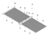
互いに回動自在に連結された複数の床パネルを互いに回動させることにより折り畳み可能に形成された足場本体を備え、
前記足場本体は、各床パネルが互いに厚さ方向に重なり合うように折り畳まれた状態で各床パネルの厚さ方向が橋軸直角方向を向くように縦向きにして橋梁下方の地上から吊り上げ可能に形成されるとともに、橋梁本体側に吊り上げた状態で橋軸直角方向に伸長するように展開可能に形成されている
ことを特徴とする吊足場。 - 前記足場本体を他の足場本体と橋軸方向に連結可能に形成した
ことを特徴とする請求項1記載の吊足場。 - 前記床パネル同士を着脱可能に連結した
ことを特徴とする請求項1または2記載の吊足場。 - 橋梁本体から吊り下げて設置される吊足場の設置方法において、
互いに回動自在に連結された複数の床パネルを互いに回動させることにより折り畳み可能に形成された足場本体を用い、
前記各床パネルが互いに厚さ方向に重なり合うように橋軸直角方向に折り畳まれた足場本体を各床パネルの厚さ方向が橋軸直角方向を向くように縦向きにして橋梁下方の地上に配置しておき、
折り畳まれた状態の足場本体を橋梁本体側に吊り上げるとともに、橋軸直角方向に伸長するように展開することにより、橋軸直角方向に水平に延びる吊足場を形成する
ことを特徴とする吊足場の設置方法。 - 折り畳まれた状態の足場本体の橋軸直角方向中央部を吊り上げるとともに、足場本体を橋軸直角方向中央側から橋軸直角方向外側に向かってそれぞれ伸長させる
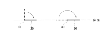
ことを特徴とする請求項4記載の吊足場の設置方法。 - 前記足場本体を吊り上げる工程で一部の床パネル同士の連結部分の回動を規制する
ことを特徴とする請求項4または5記載の吊足場の設置方法。 - 橋軸直角方向に伸長した複数の足場本体を橋軸方向に連結することにより、吊足場を橋軸方向に順次設置する
ことを特徴とする請求項4、5または6記載の吊足場の設置方法。 - 前記床パネル同士が着脱可能に連結された足場本体を用いる
ことを特徴とする請求項4、5、6または7記載の吊足場の設置方法。
Priority Applications (1)
| Application Number | Priority Date | Filing Date | Title |
|---|---|---|---|
| JP2019191437A JP7309565B2 (ja) | 2019-10-18 | 2019-10-18 | 吊足場及びその設置方法 |
Applications Claiming Priority (1)
| Application Number | Priority Date | Filing Date | Title |
|---|---|---|---|
| JP2019191437A JP7309565B2 (ja) | 2019-10-18 | 2019-10-18 | 吊足場及びその設置方法 |
Publications (2)
| Publication Number | Publication Date |
|---|---|
| JP2021067028A JP2021067028A (ja) | 2021-04-30 |
| JP7309565B2 true JP7309565B2 (ja) | 2023-07-18 |
Family
ID=75637766
Family Applications (1)
| Application Number | Title | Priority Date | Filing Date |
|---|---|---|---|
| JP2019191437A Active JP7309565B2 (ja) | 2019-10-18 | 2019-10-18 | 吊足場及びその設置方法 |
Country Status (1)
| Country | Link |
|---|---|
| JP (1) | JP7309565B2 (ja) |
Families Citing this family (1)
| Publication number | Priority date | Publication date | Assignee | Title |
|---|---|---|---|---|
| JP7152553B1 (ja) | 2021-04-12 | 2022-10-12 | 株式会社リブドゥコーポレーション | 吸収性物品 |
Citations (6)
| Publication number | Priority date | Publication date | Assignee | Title |
|---|---|---|---|---|
| JP2000096819A (ja) | 1998-09-18 | 2000-04-04 | Seiko Kiki Kk | 歩道橋、架線ビーム等の作業足場の仮設工法 |
| JP2004316070A (ja) | 2003-04-10 | 2004-11-11 | Geo Frontier Kk | 橋梁用の防護足場ユニット、及びこれを用いた防護工法 |
| JP2005299280A (ja) | 2004-04-14 | 2005-10-27 | Samu:Kk | 移動足場システム |
| JP2013217069A (ja) | 2012-04-06 | 2013-10-24 | Nippon Steel Topy Bridge Co Ltd | 吊り足場ユニットと足場の架設工法 |
| JP2014024502A (ja) | 2012-07-30 | 2014-02-06 | Kawasaki Heavy Ind Ltd | 浮体ユニット、浮橋および浮体桟橋 |
| JP2014145203A (ja) | 2013-01-29 | 2014-08-14 | Hiroshima Univ | シザーズ式伸縮構造 |
Family Cites Families (4)
| Publication number | Priority date | Publication date | Assignee | Title |
|---|---|---|---|---|
| US4488833A (en) * | 1982-04-27 | 1984-12-18 | Kaiser Aluminum & Chemical Corporation | Rapidly deployed assault vehicle surfacing or trackway system |
| JPS5980810A (ja) * | 1982-10-30 | 1984-05-10 | ケーブル足場株式会社 | 足場装置 |
| JPH0442434Y2 (ja) * | 1986-11-18 | 1992-10-07 | ||
| JPH07103679B2 (ja) * | 1990-09-28 | 1995-11-08 | 株式会社新成工業 | 吊り足場組立て工法とそれに使用される足場材 |
-
2019
- 2019-10-18 JP JP2019191437A patent/JP7309565B2/ja active Active
Patent Citations (6)
| Publication number | Priority date | Publication date | Assignee | Title |
|---|---|---|---|---|
| JP2000096819A (ja) | 1998-09-18 | 2000-04-04 | Seiko Kiki Kk | 歩道橋、架線ビーム等の作業足場の仮設工法 |
| JP2004316070A (ja) | 2003-04-10 | 2004-11-11 | Geo Frontier Kk | 橋梁用の防護足場ユニット、及びこれを用いた防護工法 |
| JP2005299280A (ja) | 2004-04-14 | 2005-10-27 | Samu:Kk | 移動足場システム |
| JP2013217069A (ja) | 2012-04-06 | 2013-10-24 | Nippon Steel Topy Bridge Co Ltd | 吊り足場ユニットと足場の架設工法 |
| JP2014024502A (ja) | 2012-07-30 | 2014-02-06 | Kawasaki Heavy Ind Ltd | 浮体ユニット、浮橋および浮体桟橋 |
| JP2014145203A (ja) | 2013-01-29 | 2014-08-14 | Hiroshima Univ | シザーズ式伸縮構造 |
Also Published As
| Publication number | Publication date |
|---|---|
| JP2021067028A (ja) | 2021-04-30 |
Similar Documents
| Publication | Publication Date | Title |
|---|---|---|
| JP6004353B2 (ja) | 高架道路用コンクリート床版の架け替え方法 | |
| US9267287B1 (en) | Pre-fabricated threaded bar assemblies | |
| US20150021119A1 (en) | Self-launching movable scaffolding system | |
| CN107338727B (zh) | 一种整体拆、装防撞墙模板及其步履式轨道吊移系统 | |
| JP6702835B2 (ja) | 多径間連続橋の橋桁架設方法 | |
| CN106592406B (zh) | 下承式系杆拱桥及其施工方法 | |
| JP5097313B2 (ja) | 吊り足場及びその架設方法 | |
| EA006995B1 (ru) | Способ и устройство для строительства из сборных и каркасных элементов | |
| KR20070010143A (ko) | 관절형 작업 플랫폼 지지 장치, 작업 플랫폼 시스템 및이들의 사용 방법 | |
| WO2014200443A1 (en) | Self-launching movable scaffolding system | |
| JP4777922B2 (ja) | 移動吊支保工 | |
| JP2006090026A (ja) | 既設鋼部材アーチ橋の補修・補強構造 | |
| JP2007205014A (ja) | 橋梁の架設方法及び装置 | |
| CN107882328A (zh) | 大跨度钢桁架悬吊结构的施工方法 | |
| CN114855624B (zh) | 一种悬浇连续箱梁横隔板的内模吊架结构及其施工方法 | |
| JP7309565B2 (ja) | 吊足場及びその設置方法 | |
| CN113026528A (zh) | 一种山林空间曲线钢结构栈道安装方法 | |
| JP2020002778A (ja) | 橋脚構築方法 | |
| JP3025227B2 (ja) | 橋梁の架設方法 | |
| KR20070010449A (ko) | 아치교의 시공 방법 | |
| CN206408510U (zh) | 下承式系杆拱桥 | |
| CN212452315U (zh) | 拼装模块及模块化施工平台 | |
| KR102085928B1 (ko) | 스플라이스 파일캡을 이용한 가설교량 및 그 시공방법 | |
| JP4336659B2 (ja) | 上路式吊床版橋の構築方法 | |
| CN114575259B (zh) | 一种模板调节装置 |
Legal Events
| Date | Code | Title | Description |
|---|---|---|---|
| A621 | Written request for application examination |
Free format text: JAPANESE INTERMEDIATE CODE: A621 Effective date: 20220527 |
|
| A977 | Report on retrieval |
Free format text: JAPANESE INTERMEDIATE CODE: A971007 Effective date: 20230216 |
|
| A131 | Notification of reasons for refusal |
Free format text: JAPANESE INTERMEDIATE CODE: A131 Effective date: 20230222 |
|
| A521 | Request for written amendment filed |
Free format text: JAPANESE INTERMEDIATE CODE: A523 Effective date: 20230412 |
|
| TRDD | Decision of grant or rejection written | ||
| A01 | Written decision to grant a patent or to grant a registration (utility model) |
Free format text: JAPANESE INTERMEDIATE CODE: A01 Effective date: 20230621 |
|
| A61 | First payment of annual fees (during grant procedure) |
Free format text: JAPANESE INTERMEDIATE CODE: A61 Effective date: 20230705 |
|
| R150 | Certificate of patent or registration of utility model |
Ref document number: 7309565 Country of ref document: JP Free format text: JAPANESE INTERMEDIATE CODE: R150 |