JP7311994B2 - IMAGE PROCESSING DEVICE, IMAGING DEVICE, IMAGE PROCESSING METHOD, AND PROGRAM - Google Patents
IMAGE PROCESSING DEVICE, IMAGING DEVICE, IMAGE PROCESSING METHOD, AND PROGRAM Download PDFInfo
- Publication number
- JP7311994B2 JP7311994B2 JP2019061356A JP2019061356A JP7311994B2 JP 7311994 B2 JP7311994 B2 JP 7311994B2 JP 2019061356 A JP2019061356 A JP 2019061356A JP 2019061356 A JP2019061356 A JP 2019061356A JP 7311994 B2 JP7311994 B2 JP 7311994B2
- Authority
- JP
- Japan
- Prior art keywords
- noise
- color
- color difference
- captured image
- image
- Prior art date
- Legal status (The legal status is an assumption and is not a legal conclusion. Google has not performed a legal analysis and makes no representation as to the accuracy of the status listed.)
- Active
Links
Images



Classifications
-
- H—ELECTRICITY
- H04—ELECTRIC COMMUNICATION TECHNIQUE
- H04N—PICTORIAL COMMUNICATION, e.g. TELEVISION
- H04N9/00—Details of colour television systems
- H04N9/64—Circuits for processing colour signals
- H04N9/646—Circuits for processing colour signals for image enhancement, e.g. vertical detail restoration, cross-colour elimination, contour correction, chrominance trapping filters
-
- H—ELECTRICITY
- H04—ELECTRIC COMMUNICATION TECHNIQUE
- H04N—PICTORIAL COMMUNICATION, e.g. TELEVISION
- H04N23/00—Cameras or camera modules comprising electronic image sensors; Control thereof
- H04N23/80—Camera processing pipelines; Components thereof
- H04N23/81—Camera processing pipelines; Components thereof for suppressing or minimising disturbance in the image signal generation
-
- H—ELECTRICITY
- H04—ELECTRIC COMMUNICATION TECHNIQUE
- H04N—PICTORIAL COMMUNICATION, e.g. TELEVISION
- H04N23/00—Cameras or camera modules comprising electronic image sensors; Control thereof
- H04N23/80—Camera processing pipelines; Components thereof
- H04N23/84—Camera processing pipelines; Components thereof for processing colour signals
- H04N23/88—Camera processing pipelines; Components thereof for processing colour signals for colour balance, e.g. white-balance circuits or colour temperature control
-
- H—ELECTRICITY
- H04—ELECTRIC COMMUNICATION TECHNIQUE
- H04N—PICTORIAL COMMUNICATION, e.g. TELEVISION
- H04N25/00—Circuitry of solid-state image sensors [SSIS]; Control thereof
- H04N25/10—Circuitry of solid-state image sensors [SSIS]; Control thereof for transforming different wavelengths into image signals
- H04N25/11—Arrangement of colour filter arrays [CFA]; Filter mosaics
- H04N25/13—Arrangement of colour filter arrays [CFA]; Filter mosaics characterised by the spectral characteristics of the filter elements
- H04N25/134—Arrangement of colour filter arrays [CFA]; Filter mosaics characterised by the spectral characteristics of the filter elements based on three different wavelength filter elements
-
- H—ELECTRICITY
- H04—ELECTRIC COMMUNICATION TECHNIQUE
- H04N—PICTORIAL COMMUNICATION, e.g. TELEVISION
- H04N25/00—Circuitry of solid-state image sensors [SSIS]; Control thereof
- H04N25/60—Noise processing, e.g. detecting, correcting, reducing or removing noise
- H04N25/61—Noise processing, e.g. detecting, correcting, reducing or removing noise the noise originating only from the lens unit, e.g. flare, shading, vignetting or "cos4"
-
- H—ELECTRICITY
- H04—ELECTRIC COMMUNICATION TECHNIQUE
- H04N—PICTORIAL COMMUNICATION, e.g. TELEVISION
- H04N9/00—Details of colour television systems
- H04N9/79—Processing of colour television signals in connection with recording
- H04N9/7908—Suppression of interfering signals at the reproducing side, e.g. noise
Landscapes
- Engineering & Computer Science (AREA)
- Multimedia (AREA)
- Signal Processing (AREA)
- Physics & Mathematics (AREA)
- Spectroscopy & Molecular Physics (AREA)
- Processing Of Color Television Signals (AREA)
- Color Television Image Signal Generators (AREA)
Description
本発明は、画像処理装置、撮像装置、画像処理方法、及びプログラムに関する。 The present invention relates to an image processing device, an imaging device, an image processing method, and a program.
従来、撮像装置において、ゲイン、温度、露光時間などに起因するノイズの抑圧制御や、ホワイトバランス(WB)補正の制御などが行われている。低照度環境下においては、視認性を高めるために大きなゲインを使用する場合があるが、この場合、ゲインに起因するノイズも大きくなる。その結果、撮像画像の低輝度領域においてはノイズ成分が支配的となり、ノイズに起因する色づきが発生して画質が低下するという問題があった。 2. Description of the Related Art Conventionally, in an imaging apparatus, noise suppression control caused by gain, temperature, exposure time, etc., white balance (WB) correction control, and the like are performed. In a low-illuminance environment, a large gain may be used to improve visibility, but in this case, the noise caused by the gain also becomes large. As a result, the noise component becomes dominant in the low-luminance region of the captured image, and there is a problem that coloring due to the noise occurs and the image quality deteriorates.
この問題を解決するために、ゲインに基づいてノイズの抑制制御を行う技術が知られている。例えば、特許文献1には、撮像素子により得られた映像信号を表示する場合に、測光値に基づいて決定したゲインや露光時間といった撮影条件に基づいて、映像信号のうちノイズ成分を推測して抑圧することが開示されている。また、特許文献2には、発生するノイズ成分のうち、特に色ノイズを抑圧するための技術が開示されている。具体的には、露光時間及び温度に応じて変化するノイズレベルを求め、求めたノイズレベルに対応する色ずれのレベルを算出し、ゲインに基づいて色成分の抑圧処理を実施することが開示されている。 In order to solve this problem, a technique is known that performs noise suppression control based on the gain. For example, in Patent Document 1, when displaying a video signal obtained by an image pickup device, noise components in the video signal are estimated based on shooting conditions such as gain and exposure time determined based on a photometric value. Suppression is disclosed. Further, Patent Document 2 discloses a technique for suppressing color noise, among the generated noise components. Specifically, it discloses obtaining a noise level that changes according to exposure time and temperature, calculating a level of color shift corresponding to the obtained noise level, and performing color component suppression processing based on the gain. ing.
低輝度領域に発生するノイズに起因する色づきは、撮影条件、特にホワイトバランス補正のゲイン(ホワイトバランスゲイン)に応じて大きく変化する。また、低輝度領域以外の領域についても、ノイズに起因する色づきはホワイトバランスゲインの影響を受ける。しかしながら、従来の技術では、ホワイトバランス補正がノイズに起因する色づきに与える影響が考慮されていなかった。 Coloring caused by noise occurring in a low-luminance area varies greatly depending on shooting conditions, particularly the gain of white balance correction (white balance gain). Also, in areas other than the low-luminance area, coloring due to noise is affected by the white balance gain. However, conventional techniques do not take into consideration the effect of white balance correction on coloring caused by noise.
本発明はこのような状況に鑑みてなされたものであり、ホワイトバランス補正がノイズに起因する色づきに与える影響を考慮して撮像画像の色成分の抑圧処理を行う技術を提供することを目的とする。 SUMMARY OF THE INVENTION The present invention has been made in view of such circumstances, and it is an object of the present invention to provide a technique for suppressing color components of a captured image in consideration of the effect of white balance correction on coloring caused by noise. do.
上記課題を解決するために、本発明は、ホワイトバランス補正が行われた撮像画像に含まれるノイズの色差成分を推定する推定手段と、前記ノイズの色差成分の大きさに基づいて色抑圧処理の強度を決定する決定手段と、前記撮像画像に対して前記決定された強度で前記色抑圧処理を適用する処理手段と、を備え、前記撮像画像は、撮像手段による光電変換により生成される画像信号に対して全色共通のゲインと色毎に決定されるホワイトバランスゲインとを適用することにより得られ、前記推定手段は、前記ゲイン及び前記ホワイトバランスゲインに基づいて、前記ノイズの色差成分を推定することを特徴とする画像処理装置を提供する。 In order to solve the above problems, the present invention provides an estimating means for estimating color difference components of noise contained in a captured image subjected to white balance correction, and color suppression processing based on the magnitude of the color difference components of the noise. determining means for determining an intensity; and processing means for applying the color suppression processing to the captured image with the determined intensity, wherein the captured image is an image signal generated by photoelectric conversion by the imaging means. obtained by applying a gain common to all colors and a white balance gain determined for each color, and the estimation means estimates the color difference component of the noise based on the gain and the white balance gain To provide an image processing apparatus characterized by :
本発明によれば、ホワイトバランス補正がノイズに起因する色づきに与える影響を考慮して撮像画像の色成分の抑圧処理を行うことが可能となる。 According to the present invention, it is possible to suppress the color components of a captured image in consideration of the effect of white balance correction on coloring caused by noise.
なお、本発明のその他の特徴及び利点は、添付図面及び以下の発明を実施するための形態における記載によって更に明らかになるものである。 Other features and advantages of the present invention will become more apparent from the accompanying drawings and the description in the following detailed description.
以下、添付図面を参照して実施形態を詳しく説明する。尚、以下の実施形態は特許請求の範囲に係る発明を限定するものでない。実施形態には複数の特徴が記載されているが、これらの複数の特徴の全てが発明に必須のものとは限らず、また、複数の特徴は任意に組み合わせられてもよい。さらに、添付図面においては、同一若しくは同様の構成に同一の参照番号を付し、重複した説明は省略する。 Hereinafter, embodiments will be described in detail with reference to the accompanying drawings. It should be noted that the following embodiments do not limit the invention according to the scope of claims. Although multiple features are described in the embodiments, not all of these multiple features are essential to the invention, and multiple features may be combined arbitrarily. Furthermore, in the accompanying drawings, the same or similar configurations are denoted by the same reference numerals, and redundant description is omitted.
[第1の実施形態]
図1は、画像処理装置を含む撮像装置100の構成を示すブロック図である。図1において、レンズ10から入射した光は、CCDやCMOSセンサに代表される撮像素子20の受光面上に結像する。撮像素子20は、結像した光を光電変換により画像信号に変換して出力する。画像処理部30は、撮像素子20から出力された画像信号に対して、色変換、AE処理、ホワイトバランス補正(WB補正)、階調変換を行うγ処理などの、各種画像処理を行う。システム制御部40は、制御プログラムが格納されたROMとワークメモリとして使用されるRAMとを含み、制御プログラムを実行することにより撮像装置100全体を制御する。
[First Embodiment]
FIG. 1 is a block diagram showing the configuration of an
画像処理部30において、ゲイン制御部31は、撮像素子20による光電変換により生成された画像信号に対して適用するゲインを決定し、決定したゲインを画像信号に適用する。露光時間制御部32は、露光時間を決定し、撮像素子20に対して露光時間の制御を行う。ノイズレベル推定部33は、ゲイン制御部31により決定されたゲインに基づいて、撮像画像に含まれるノイズのレベル(ノイズレベル)を推定する。なお、ノイズレベルは、ゲインを含む様々な撮影条件の影響を受ける。ノイズレベルに影響を与える撮影条件の例として、露光時間がある。従って、ノイズレベル推定部33は、ゲイン制御部31により決定されたゲインに加えて、露光時間制御部32によって決定された露光時間に基づいてノイズレベルを推定してもよい。
In the
WBゲイン制御部34は、画像信号において適切なホワイトバランスが得られるよう、画像信号の各色にかけるゲイン(ホワイトバランスゲイン)を決定する。即ち、ゲイン制御部31のゲインは全色共通のゲインであるが、ホワイトバランスゲイン(WBゲイン)は色毎に決定される。WBゲイン制御部34は、画像信号に対して、色毎に決定されたWBゲインを適用する信号処理(WB補正)を行う。
The WB
ノイズ輝度・色差推定部35は、ノイズレベル推定部33により推定されたノイズレベルに対し、WBゲイン制御部34により決定された色毎のWBゲインをかけることで、実際に出力されるノイズ(撮像画像に含まれるノイズ)の輝度成分及び色差成分を推定する。
The noise luminance/
色抑圧範囲決定部36は、ノイズ輝度・色差推定部35によって推定されたノイズの輝度成分に基づいて、色成分の抑圧処理(色抑圧処理)を適用する輝度範囲を決定する。色抑圧レベル決定部37は、ノイズ輝度・色差推定部35により推定されたノイズの色差成分に基づいて、色抑圧処理の強度を決定する。色抑圧部38は、ホワイトバランス補正が行われた撮像画像の、色抑圧範囲決定部36により決定された輝度範囲内の輝度を持つ画素に対して、色抑圧レベル決定部37により決定された強度で色抑圧処理を適用する。
The color suppression
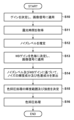
図2は、第1の実施形態に係る画像処理のフローチャートである。撮像素子20による光電変換により生成された画像信号が画像処理部30に入力されると、本フローチャートの処理が開始する。
FIG. 2 is a flowchart of image processing according to the first embodiment. When an image signal generated by photoelectric conversion by the
S10で、ゲイン制御部31は、全色共通のゲインを決定し、決定したゲインを画像信号に適用する。S11で、露光時間制御部32は、画像信号の露光時間を取得する。S12で、ノイズレベル推定部33は、S10において決定されたゲインに基づいてノイズレベルを推定する。なお、ノイズレベル推定部33は、S10において決定されたゲインに加えて、S11において取得された露光時間に基づいてノイズレベルを推定してもよい。
In S10, the
図3は、ノイズレベルを推定する処理の概念図である。図3に示されるように、ゲイン及び露光時間に対応するノイズレベルが推定される。 FIG. 3 is a conceptual diagram of processing for estimating the noise level. As shown in FIG. 3, the noise level corresponding to gain and exposure time is estimated.
図2に戻り、S13で、WBゲイン制御部34は、画像信号の色毎にWBゲインを決定し、決定したWBゲインを画像信号に適用する。S14で、ノイズ輝度・色差推定部35は、ノイズレベル及びWBゲインに基づいて色毎にノイズ信号推定値を算出する。そして、ノイズ輝度・色差推定部35は、算出された色毎のノイズ信号推定値から、推定ノイズ輝度値(ノイズの輝度成分)及び推定ノイズ色差値(ノイズの色差成分)を算出する。
Returning to FIG. 2, in S13, the WB
図4は、色毎のノイズ信号推定値を算出する処理の概念図である。撮像素子20により生成される画像信号に生じるノイズは電気的な信号であり、ゲイン制御部31のゲインは全色共通である。そのため、図4の左側に示すように、ノイズレベル推定部33により推定されるノイズレベルには、色毎の相違は生じない。一方、WBゲインは色毎に決定される。そのため、図4の右側に示すように、ノイズ信号推定値は、色毎に異なる場合があり、ノイズの色づきが発生する場合がある。ノイズ輝度・色差推定部35は、このような色毎のノイズ信号推定値から、ノイズの輝度成分及び色差成分を算出する。
FIG. 4 is a conceptual diagram of processing for calculating a noise signal estimated value for each color. The noise generated in the image signal generated by the
なお、S12及びS14の処理から理解できるように、ノイズレベルはゲイン制御部31のゲインに基づいて推定され、ノイズの輝度成分及び色差成分はノイズレベル及びWBゲインに基づいて算出される。従って、S12及びS14の処理全体としては、ホワイトバランス補正が行われた撮像画像に含まれるノイズの輝度成分及び色差成分が、全色共通のゲイン及び色毎に決定されるWBゲインに基づいて推定される。
As can be understood from the processing of S12 and S14, the noise level is estimated based on the gain of the
図2に戻り、S15で、色抑圧範囲決定部36は、ノイズの輝度成分の大きさに基づいて、色抑圧処理を適用する輝度範囲を決定する。また、色抑圧レベル決定部37は、ノイズの色差成分の大きさに基づいて、色抑圧処理の強度を決定する。
Returning to FIG. 2, in S15, the color suppression
図5は、色抑圧処理を適用する輝度範囲を決定する処理の概念図である。推定ノイズ輝度以下の輝度の範囲(ノイズの輝度成分の大きさ以下の輝度の範囲)が、色抑圧処理を適用する輝度範囲として決定される。なお、色抑圧処理を適用する輝度範囲は、推定ノイズ輝度未満の輝度の範囲(ノイズの輝度成分の大きさ未満の輝度の範囲)であってもよい。このように色抑圧処理の輝度範囲を決定することにより、ノイズに起因する色づきが目立つ低輝度領域に対して色抑圧処理を適用することが可能となる。 FIG. 5 is a conceptual diagram of processing for determining a luminance range to which color suppression processing is applied. A luminance range equal to or less than the estimated noise luminance (luminance range equal to or less than the magnitude of the luminance component of noise) is determined as the luminance range to which color suppression processing is applied. Note that the luminance range to which the color suppression process is applied may be a luminance range less than the estimated noise luminance (a luminance range less than the magnitude of the luminance component of the noise). By determining the luminance range of the color suppression process in this way, it becomes possible to apply the color suppression process to a low-luminance region in which coloring due to noise is conspicuous.
図6は、ノイズの色差成分の大きさΔCrCbの概念図である。ΔCrCbは、下記の式(1)に従って算出される。
ΔCrCb=√(Cr2+Cb2) ・・・(1)
ここで、Cr及びCbは、S14においてノイズ輝度・色差推定部35により算出された推定ノイズ色差値(ノイズの色差成分)である。ノイズの色差成分の大きさΔCrCbを求めることで、ノイズに起因する色づきの度合いを判定することができる。
FIG. 6 is a conceptual diagram of the magnitude ΔCrCb of the chrominance component of noise. ΔCrCb is calculated according to the following formula (1).
ΔCrCb=√(Cr 2 +Cb 2 ) (1)
Here, Cr and Cb are the estimated noise color difference values (noise color difference components) calculated by the noise luminance/color
図7は、色抑圧処理の強度を決定する処理の概念図である。図7に示すように、ノイズの色差成分の大きさΔCrCbに応じて、色抑圧処理の強度が変化する。 FIG. 7 is a conceptual diagram of processing for determining the intensity of color suppression processing. As shown in FIG. 7, the strength of the color suppression process changes according to the magnitude ΔCrCb of the color difference component of noise.
図2に戻り、S16で、色抑圧部38は、WB補正が行われた撮像画像に対して色抑圧処理を適用する。色抑圧処理は、撮像画像のうちS15において決定された輝度範囲内の輝度を持つ画素に対して、S15において決定された強度で行われる。
Returning to FIG. 2, in S16, the
以上説明したように、第1の実施形態によれば、撮像装置100は、撮像素子20による光電変換により生成される画像信号に対して全色共通のゲインと色毎に決定されるWBゲインとを適用することにより、撮像画像を取得する(図2のS10及びS13)。そして、撮像装置100は、全色共通のゲインと色毎に決定されるWBゲインとに基づいて、撮像画像に含まれるノイズの輝度成分及び色差成分を推定する(図2のS12及びS14)。そして、撮像装置100は、ノイズの輝度成分の大きさに基づいて、色抑圧処理を適用する輝度範囲を決定し、ノイズの色差成分の大きさに基づいて、色抑圧処理の強度を決定する。そして、撮像装置100は、撮像画像のうち決定された輝度範囲内の輝度を持つ画素に対して、決定された強度で色抑圧処理を適用する。これにより、WB補正がノイズに起因する色づきに与える影響を考慮して撮像画像の色成分の抑圧処理を行うことが可能となる。
As described above, according to the first embodiment, the
なお、撮像装置100は、色抑圧処理を適用する輝度範囲を決定せずに、輝度に関わらず撮像画像に対して色抑圧処理を適用してもよい。この場合、ノイズに起因する色づきがそれほど目立たない高輝度領域においても色抑圧処理が適用されるが、WB補正がノイズに起因する色づきに与える影響は、色抑圧処理において依然として考慮されている。
Note that the
また、図7の例ではノイズの色差成分の大きさが大きいほど色抑圧処理の強度も大きいが、ノイズの色差成分の大きさと色抑圧処理の強度との具体的な関係は特に限定されない。色抑圧処理の強度がノイズの色差成分の大きさに基づいて決定される限り、WB補正がノイズに起因する色づきに与える影響は、色抑圧処理において依然として考慮されている。 In the example of FIG. 7, the intensity of color suppression processing increases as the magnitude of the color difference component of noise increases, but the specific relationship between the magnitude of the color difference component of noise and the intensity of color suppression processing is not particularly limited. As long as the intensity of color suppression processing is determined based on the magnitude of the color difference components of noise, the effect of WB correction on coloring caused by noise is still considered in color suppression processing.
[第2の実施形態]
第2の実施形態では、色抑圧処理を適用する色差範囲を決定し、撮像画像のうち決定された色差範囲内の色差を持つ画素に対して色抑圧処理を適用する構成について説明する。本実施形態において、撮像装置100の基本的な構成は第1の実施形態と同様である(図1参照)。以下、主に第1の実施形態と異なる点について説明する。
[Second embodiment]
In the second embodiment, a configuration will be described in which a color difference range to which color suppression processing is applied is determined, and color suppression processing is applied to pixels having color differences within the determined color difference range in a captured image. In this embodiment, the basic configuration of the
図8は、第2の実施形態に係る画像処理のフローチャートである。図8において、図2と同一又は同様の処理が行われるステップには図2と同一の符号を付し、その説明を省略する。撮像素子20による光電変換により生成された画像信号が画像処理部30に入力されると、本フローチャートの処理が開始する。
FIG. 8 is a flowchart of image processing according to the second embodiment. In FIG. 8, steps in which the same or similar processing as in FIG. 2 is performed are assigned the same reference numerals as in FIG. 2, and description thereof will be omitted. When an image signal generated by photoelectric conversion by the
S26で、色抑圧範囲決定部36は、S14において算出されたノイズの色差成分に基づいて、色抑圧処理を適用する色差範囲を決定する。
In S26, the color suppression
図9は、色抑圧処理を適用する色差範囲を決定する処理の概念図である。ノイズの色差成分の近傍の色差の範囲が、色抑圧処理を適用する色差範囲として決定される。ここで言う「近傍」とは、撮像画像の画素が持つ色差がノイズの色差成分に起因する可能性が高いと考えられる範囲であり、例えば図9に示すように閾値ThCr及びThCbを用いて定めることができる。即ち、図9の例では、0≦推定Cr≦推定Cr+ThCr、かつ0≦推定Cb≦推定Cb+ThCbを満たす色差の場合が、色抑圧処理を適用する色差範囲として決定される。 FIG. 9 is a conceptual diagram of processing for determining a color difference range to which color suppression processing is applied. A color difference range in the vicinity of the noise color difference component is determined as a color difference range to which color suppression processing is applied. The term “neighborhood” as used herein refers to a range in which the color difference of the pixels of the captured image is likely to be caused by the color difference component of noise. For example, as shown in FIG. be able to. That is, in the example of FIG. 9, the color difference range that satisfies 0≦estimated Cr≦estimated Cr+ThCr and 0≦estimated Cb≦estimated Cb+ThCb is determined as the color difference range to which the color suppression process is applied.
なお、色抑圧処理を適用する色差範囲は、ノイズの色差成分に基づいて決定される限り、ノイズの色差成分の近傍の色差の範囲に限定されない。 Note that the color difference range to which the color suppression process is applied is not limited to the color difference range in the vicinity of the noise color difference component as long as it is determined based on the noise color difference component.
図8に戻り、S27で、色抑圧部38は、WB補正が行われた撮像画像に対して色抑圧処理を適用する。色抑圧処理は、撮像画像のうち、S15において決定された輝度範囲内の輝度を持ち、S26において決定された色差範囲内の色差を持つ画素に対して、S15において決定された強度で行われる。
Returning to FIG. 8, in S27, the
以上説明したように、第2の実施形態によれば、撮像装置100は、WB補正が行われた撮像画像に含まれるノイズの色差成分に基づいて、色抑圧処理を適用する色差範囲を決定する。そして、撮像装置100は、撮像画像のうち決定された色差範囲内の色差を持つ画素に対して色抑圧処理を適用する。これにより、WB補正がノイズに起因する色づきに与える影響を考慮して撮像画像の色成分の抑圧処理を行うことが可能となる。
As described above, according to the second embodiment, the
[第3の実施形態]
第1の実施形態では、全色共通のゲインと色毎に決定されるWBゲインとに基づいて、撮像画像に含まれるノイズの輝度成分及び色差成分を推定する構成について説明した。しかしながら、ノイズの輝度成分及び色差成分を推定する方法は、第1の実施形態で説明した方法に限定されない。第3の実施形態では、撮像画像の遮光領域に対応する領域の画素値、又はユーザ指示に従って選択された撮像画像の部分領域の画素値に基づいて、ノイズの輝度成分及び色差成分を推定する構成について説明する。
[Third Embodiment]
In the first embodiment, the configuration for estimating the luminance component and color difference component of noise included in the captured image based on the gain common to all colors and the WB gain determined for each color has been described. However, the method of estimating the luminance component and color difference component of noise is not limited to the method described in the first embodiment. In the third embodiment, the luminance component and the color difference component of noise are estimated based on the pixel value of the area corresponding to the light-shielded area of the captured image or the pixel value of the partial area of the captured image selected according to the user's instruction. will be explained.
図10は、画像処理装置を含む撮像装置200の構成を示すブロック図である。撮像装置200は、図1に示す撮像装置100と比べて、画像処理部30の代わりに画像処理部130を備える点が異なる。また、画像処理部130は、画像処理部30と比べて、ノイズレベル推定部33及びノイズ輝度・色差推定部35の代わりにノイズ推定領域選択部133及びノイズ輝度・色差推定部135を備える点が異なる。以下、主に第1の実施形態と異なる点について説明する。
FIG. 10 is a block diagram showing the configuration of an
ノイズ推定領域選択部133は、撮像画像においてノイズ推定を行う領域(ノイズ推定領域)を選択する。例えば、ノイズ推定領域選択部133は、撮像画像において撮像素子20の遮光領域に対応する領域を選択してもよいし、ユーザ指示に従って撮像画像の部分領域を選択してもよい。後者の場合、ユーザは、撮像画像における低輝度領域が選択されるように指示を行う。ノイズ輝度・色差推定部135は、撮像画像のノイズ推定領域の画素値に基づいて、ノイズの輝度成分及び色差成分を推定する。例えば、ノイズ輝度・色差推定部135は、撮像画像のノイズ推定領域の画素値から輝度値及び色差値を算出し、算出された輝度値及び色差値をノイズの輝度成分及び色差成分の推定値として用いる。
The noise estimation
図11は、撮像素子20の遮光領域及び非遮光領域を示す概念図である。レンズ10から入射した光が結像するイメージサークルが撮像素子20の撮像面よりも狭い場合、イメージサークルの外の領域(遮光領域)は光を受光しない。従って、遮光領域をノイズ推定領域として選択することで、撮像画像の遮光領域に対応する領域の画素値をノイズと見なすことが可能である。
FIG. 11 is a conceptual diagram showing the light shielding area and the non-light shielding area of the
図12は、第3の実施形態に係る画像処理のフローチャートである。図12において、図2と同一又は同様の処理が行われるステップには図2と同一の符号を付し、その説明を省略する。撮像素子20による光電変換により生成された画像信号が画像処理部130に入力されると、本フローチャートの処理が開始する。
FIG. 12 is a flowchart of image processing according to the third embodiment. In FIG. 12, steps in which the same or similar processing as in FIG. 2 is performed are assigned the same reference numerals as in FIG. 2, and description thereof will be omitted. When an image signal generated by photoelectric conversion by the
S32で、ノイズ推定領域選択部133は、撮像画像のノイズ推定領域を選択する。前述の通り、ノイズ推定領域選択部133は、撮像画像において撮像素子20の遮光領域に対応する領域を選択してもよいし、ユーザ指示に従って撮像画像の部分領域を選択してもよい。S34で、ノイズ輝度・色差推定部135は、撮像画像のノイズ推定領域の画素値に基づいて、ノイズの輝度成分及び色差成分を推定する。
In S32, the noise estimation
以上説明したように、第3の実施形態によれば、撮像装置200は、撮像画像の遮光領域に対応する領域の画素値、又はユーザ指示に従って選択された撮像画像の部分領域の画素値に基づいて、ノイズの輝度成分及び色差成分を推定する。このように、第1の実施形態において説明した方法とは異なる方法によってもノイズの輝度成分及び色差成分を推定することが可能である。
As described above, according to the third embodiment, the
[その他の実施形態]
上記実施形態で用いられる撮像装置として、いわゆる一般的なデジタルスチルカメラやデジタルビデオカメラの他、監視カメラや産業・工場用カメラ、医療用カメラを用いることも可能である。これらのカメラはその用途によっては低照度下での撮像が必須となる場合があり、その場合に本発明は有用となる。さらに本発明は画像処理装置を含む撮像装置を例に説明したが、撮像装置を例えば有線または無線ネットワーク越しに制御する画像処理装置にも適用可能である。この場合、画像処理装置は各種ゲインの値を撮像装置から受信し、ノイズレベルの推定および色抑圧レベルの決定を行い、色抑圧レベルを撮像装置に送信してもよい。
[Other embodiments]
In addition to so-called general digital still cameras and digital video cameras, surveillance cameras, industrial/factory cameras, and medical cameras can also be used as imaging devices used in the above embodiments. These cameras may require imaging under low illuminance depending on the application, and the present invention is useful in such cases. Furthermore, although the present invention has been described with an imaging apparatus including an image processing apparatus as an example, it is also applicable to an image processing apparatus that controls an imaging apparatus via a wired or wireless network, for example. In this case, the image processing device may receive various gain values from the imaging device, estimate the noise level and determine the color suppression level, and transmit the color suppression level to the imaging device.
本発明は、上述の実施形態の1以上の機能を実現するプログラムを、ネットワーク又は記憶媒体を介してシステム又は装置に供給し、そのシステム又は装置のコンピュータにおける1つ以上のプロセッサーがプログラムを読出し実行する処理でも実現可能である。また、1以上の機能を実現する回路(例えば、ASIC)によっても実現可能である。 The present invention supplies a program that implements one or more functions of the above-described embodiments to a system or device via a network or a storage medium, and one or more processors in the computer of the system or device reads and executes the program. It can also be realized by processing to It can also be implemented by a circuit (for example, ASIC) that implements one or more functions.
発明は上記実施形態に制限されるものではなく、発明の精神及び範囲から離脱することなく、様々な変更及び変形が可能である。従って、発明の範囲を公にするために請求項を添付する。 The invention is not limited to the embodiments described above, and various modifications and variations are possible without departing from the spirit and scope of the invention. Accordingly, the claims are appended to make public the scope of the invention.
20…撮像素子、30…画像処理部、31…ゲイン制御部、33…ノイズレベル推定部、34…WBゲイン制御部、35…ノイズ輝度・色差推定部、36…色抑圧範囲決定部、37…色抑圧レベル決定部、38…色抑圧部、100…撮像装置
20...
Claims (10)
前記ノイズの色差成分の大きさに基づいて色抑圧処理の強度を決定する決定手段と、
前記撮像画像に対して前記決定された強度で前記色抑圧処理を適用する処理手段と、
を備え、
前記撮像画像は、撮像手段による光電変換により生成される画像信号に対して全色共通のゲインと色毎に決定されるホワイトバランスゲインとを適用することにより得られ、
前記推定手段は、前記ゲイン及び前記ホワイトバランスゲインに基づいて、前記ノイズの色差成分を推定する
ことを特徴とする画像処理装置。 estimating means for estimating color difference components of noise included in the captured image subjected to white balance correction;
determining means for determining the intensity of color suppression processing based on the magnitude of the color difference component of the noise;
a processing means for applying the color suppression processing with the determined intensity to the captured image;
with
The captured image is obtained by applying a gain common to all colors and a white balance gain determined for each color to an image signal generated by photoelectric conversion by an imaging means,
The estimation means estimates color difference components of the noise based on the gain and the white balance gain.
An image processing apparatus characterized by :
前記決定手段は、前記ノイズの輝度成分の大きさに基づいて、前記色抑圧処理を適用する輝度範囲を決定し、
前記処理手段は、前記撮像画像のうち前記輝度範囲内の輝度を持つ画素に対して前記色抑圧処理を適用する
ことを特徴とする請求項1に記載の画像処理装置。 The estimation means estimates a luminance component of the noise,
The determining means determines a luminance range to which the color suppression process is applied based on the magnitude of the luminance component of the noise;
2. The image processing apparatus according to claim 1, wherein said processing means applies said color suppression processing to pixels having luminance within said luminance range in said captured image.
ことを特徴とする請求項2に記載の画像処理装置。 The image processing apparatus according to claim 2, wherein the luminance range is a luminance range equal to or less than the magnitude of the luminance component of the noise, or a luminance range less than the magnitude of the luminance component of the noise.
前記処理手段は、前記撮像画像のうち前記色差範囲内の色差を持つ画素に対して前記色抑圧処理を適用する
ことを特徴とする請求項1乃至3のいずれか1項に記載の画像処理装置。 The determination means determines a color difference range to which the color suppression process is applied based on the color difference components of the noise,
The image processing apparatus according to any one of claims 1 to 3, wherein the processing means applies the color suppression processing to pixels having a color difference within the color difference range in the captured image. .
ことを特徴とする請求項4に記載の画像処理装置。 The image processing apparatus according to claim 4, wherein the color difference range is a color difference range near the color difference component of the noise.
前記ノイズの色差成分の大きさに基づいて色抑圧処理の強度を決定する決定手段と、
前記撮像画像に対して前記決定された強度で前記色抑圧処理を適用する処理手段と、
を備え、
前記撮像画像は、遮光領域及び非遮光領域を含む撮像手段による光電変換により生成される画像信号に対して全色共通のゲインと色毎に決定されるホワイトバランスゲインとを適用することにより得られ、
前記推定手段は、前記撮像画像の前記遮光領域に対応する領域の画素値に基づいて、前記ノイズの色差成分を推定する
ことを特徴とする画像処理装置。 estimating means for estimating color difference components of noise included in the captured image subjected to white balance correction;
determining means for determining the intensity of color suppression processing based on the magnitude of the color difference component of the noise;
a processing means for applying the color suppression processing with the determined intensity to the captured image;
with
The captured image is obtained by applying a gain common to all colors and a white balance gain determined for each color to an image signal generated by photoelectric conversion by an imaging means including a light-shielding region and a non-light-shielding region. ,
The image processing apparatus, wherein the estimating means estimates the color difference components of the noise based on pixel values of an area corresponding to the light shielding area of the captured image.
前記ノイズの色差成分の大きさに基づいて色抑圧処理の強度を決定する決定手段と、
前記撮像画像に対して前記決定された強度で前記色抑圧処理を適用する処理手段と、
ユーザ指示に従って前記撮像画像の部分領域を選択する選択手段と、
を備え、
前記撮像画像は、撮像手段による光電変換により生成される画像信号に対して全色共通のゲインと色毎に決定されるホワイトバランスゲインとを適用することにより得られ、
前記推定手段は、前記撮像画像の前記部分領域の画素値に基づいて、前記ノイズの色差成分を推定する
ことを特徴とする画像処理装置。 estimating means for estimating color difference components of noise included in the captured image subjected to white balance correction;
determining means for determining the intensity of color suppression processing based on the magnitude of the color difference component of the noise;
a processing means for applying the color suppression processing with the determined intensity to the captured image;
selection means for selecting a partial area of the captured image according to a user instruction;
with
The captured image is obtained by applying a gain common to all colors and a white balance gain determined for each color to an image signal generated by photoelectric conversion by an imaging means,
The image processing apparatus, wherein the estimating means estimates color difference components of the noise based on pixel values of the partial area of the captured image.
前記撮像手段と、
を備えることを特徴とする撮像装置。 an image processing apparatus according to any one of claims 1 to 7 ;
the imaging means;
An imaging device comprising:
ホワイトバランス補正が行われた撮像画像に含まれるノイズの色差成分を推定する推定工程と、
前記ノイズの色差成分の大きさに基づいて色抑圧処理の強度を決定する決定工程と、
前記撮像画像に対して前記決定された強度で前記色抑圧処理を適用する処理工程と、
を備え、
前記撮像画像は、撮像手段による光電変換により生成される画像信号に対して全色共通のゲインと色毎に決定されるホワイトバランスゲインとを適用することにより得られ、
前記推定工程は、前記ゲイン及び前記ホワイトバランスゲインに基づいて、前記ノイズの色差成分を推定する
ことを特徴とする画像処理方法。 An image processing method executed by an image processing device,
an estimating step of estimating color difference components of noise included in the captured image subjected to white balance correction;
a determining step of determining the intensity of color suppression processing based on the magnitude of the color difference component of the noise;
a processing step of applying the color suppression processing with the determined intensity to the captured image;
with
The captured image is obtained by applying a gain common to all colors and a white balance gain determined for each color to an image signal generated by photoelectric conversion by an imaging means,
The estimation step estimates color difference components of the noise based on the gain and the white balance gain.
An image processing method characterized by :
Priority Applications (4)
| Application Number | Priority Date | Filing Date | Title |
|---|---|---|---|
| JP2019061356A JP7311994B2 (en) | 2019-03-27 | 2019-03-27 | IMAGE PROCESSING DEVICE, IMAGING DEVICE, IMAGE PROCESSING METHOD, AND PROGRAM |
| EP20162320.4A EP3716617B1 (en) | 2019-03-27 | 2020-03-11 | Image processing apparatus, image capturing apparatus, image processing method, and storage medium |
| CN202010169666.5A CN111770321B (en) | 2019-03-27 | 2020-03-12 | Image processing apparatus, image capturing apparatus, image processing method, and storage medium |
| US16/830,677 US11445158B2 (en) | 2019-03-27 | 2020-03-26 | Image processing apparatus, image capturing apparatus, image processing method, and storage medium |
Applications Claiming Priority (1)
| Application Number | Priority Date | Filing Date | Title |
|---|---|---|---|
| JP2019061356A JP7311994B2 (en) | 2019-03-27 | 2019-03-27 | IMAGE PROCESSING DEVICE, IMAGING DEVICE, IMAGE PROCESSING METHOD, AND PROGRAM |
Publications (2)
| Publication Number | Publication Date |
|---|---|
| JP2020162049A JP2020162049A (en) | 2020-10-01 |
| JP7311994B2 true JP7311994B2 (en) | 2023-07-20 |
Family
ID=69804603
Family Applications (1)
| Application Number | Title | Priority Date | Filing Date |
|---|---|---|---|
| JP2019061356A Active JP7311994B2 (en) | 2019-03-27 | 2019-03-27 | IMAGE PROCESSING DEVICE, IMAGING DEVICE, IMAGE PROCESSING METHOD, AND PROGRAM |
Country Status (4)
| Country | Link |
|---|---|
| US (1) | US11445158B2 (en) |
| EP (1) | EP3716617B1 (en) |
| JP (1) | JP7311994B2 (en) |
| CN (1) | CN111770321B (en) |
Families Citing this family (2)
| Publication number | Priority date | Publication date | Assignee | Title |
|---|---|---|---|---|
| US11120538B2 (en) * | 2019-12-27 | 2021-09-14 | Zoox, Inc. | Sensor degradation detection and remediation |
| CN113781356B (en) * | 2021-09-18 | 2024-06-04 | 北京世纪好未来教育科技有限公司 | Training method of image denoising model, image denoising method, device and equipment |
Citations (5)
| Publication number | Priority date | Publication date | Assignee | Title |
|---|---|---|---|---|
| JP2003235055A (en) | 2002-02-12 | 2003-08-22 | Nikon Corp | Image processing apparatus, image processing program, and image processing method |
| JP2005277503A (en) | 2004-03-23 | 2005-10-06 | Fuji Photo Film Co Ltd | Image processing method and apparatus, and program |
| JP2009027619A (en) | 2007-07-23 | 2009-02-05 | Olympus Corp | Video processing apparatus and video processing program |
| JP2009100302A (en) | 2007-10-17 | 2009-05-07 | Sony Corp | Image processing apparatus, image processing method, program, imaging apparatus, and imaging method |
| JP2014165891A (en) | 2013-02-28 | 2014-09-08 | Hitachi Ltd | Imaging apparatus and image signal processor |
Family Cites Families (16)
| Publication number | Priority date | Publication date | Assignee | Title |
|---|---|---|---|---|
| JP3762725B2 (en) | 2002-08-22 | 2006-04-05 | オリンパス株式会社 | Imaging system and image processing program |
| JP2004363853A (en) * | 2003-06-04 | 2004-12-24 | Casio Comput Co Ltd | Image signal noise reduction method and noise reduction device |
| JP4547223B2 (en) * | 2004-09-28 | 2010-09-22 | オリンパス株式会社 | Imaging system, noise reduction processing apparatus, and imaging processing program |
| JP5016255B2 (en) * | 2006-02-22 | 2012-09-05 | 富士フイルム株式会社 | Noise reduction apparatus, control method thereof, control program thereof, imaging apparatus, and digital camera |
| US8711249B2 (en) * | 2007-03-29 | 2014-04-29 | Sony Corporation | Method of and apparatus for image denoising |
| CN101489033B (en) * | 2008-01-15 | 2010-09-22 | 华晶科技股份有限公司 | Image noise reduction method based on optimal original color signal |
| JP5103580B2 (en) * | 2008-03-27 | 2012-12-19 | 株式会社メガチップス | Image processing apparatus and digital camera |
| JP5366619B2 (en) * | 2008-08-12 | 2013-12-11 | キヤノン株式会社 | Image processing apparatus, imaging apparatus, image processing method, and image processing program |
| JP5529424B2 (en) * | 2009-03-11 | 2014-06-25 | ソニー株式会社 | Image processing apparatus, image processing method, and computer program |
| JP5677040B2 (en) * | 2010-11-08 | 2015-02-25 | キヤノン株式会社 | Image processing apparatus and control method thereof |
| JP5425343B2 (en) * | 2011-06-30 | 2014-02-26 | 富士フイルム株式会社 | IMAGING DEVICE, IMAGING DEVICE CONTROL METHOD, AND IMAGING DEVICE CONTROL PROGRAM |
| JP2013162248A (en) * | 2012-02-02 | 2013-08-19 | Canon Inc | Imaging device and method for controlling the same |
| JP5977565B2 (en) * | 2012-04-16 | 2016-08-24 | オリンパス株式会社 | Image processing device |
| KR101920816B1 (en) * | 2013-07-08 | 2018-11-21 | 한화테크윈 주식회사 | White balance method for shading compensation, and apparatus applied to the same |
| JP6348762B2 (en) * | 2014-04-17 | 2018-06-27 | オリンパス株式会社 | Image processing apparatus, image processing method, and image processing program |
| JP6679321B2 (en) * | 2016-01-21 | 2020-04-15 | キヤノン株式会社 | Image processing apparatus, image processing method, and program |
-
2019
- 2019-03-27 JP JP2019061356A patent/JP7311994B2/en active Active
-
2020
- 2020-03-11 EP EP20162320.4A patent/EP3716617B1/en active Active
- 2020-03-12 CN CN202010169666.5A patent/CN111770321B/en active Active
- 2020-03-26 US US16/830,677 patent/US11445158B2/en active Active
Patent Citations (5)
| Publication number | Priority date | Publication date | Assignee | Title |
|---|---|---|---|---|
| JP2003235055A (en) | 2002-02-12 | 2003-08-22 | Nikon Corp | Image processing apparatus, image processing program, and image processing method |
| JP2005277503A (en) | 2004-03-23 | 2005-10-06 | Fuji Photo Film Co Ltd | Image processing method and apparatus, and program |
| JP2009027619A (en) | 2007-07-23 | 2009-02-05 | Olympus Corp | Video processing apparatus and video processing program |
| JP2009100302A (en) | 2007-10-17 | 2009-05-07 | Sony Corp | Image processing apparatus, image processing method, program, imaging apparatus, and imaging method |
| JP2014165891A (en) | 2013-02-28 | 2014-09-08 | Hitachi Ltd | Imaging apparatus and image signal processor |
Also Published As
| Publication number | Publication date |
|---|---|
| CN111770321A (en) | 2020-10-13 |
| CN111770321B (en) | 2022-10-28 |
| EP3716617A1 (en) | 2020-09-30 |
| EP3716617B1 (en) | 2025-09-17 |
| US11445158B2 (en) | 2022-09-13 |
| JP2020162049A (en) | 2020-10-01 |
| US20200314401A1 (en) | 2020-10-01 |
Similar Documents
| Publication | Publication Date | Title |
|---|---|---|
| KR101099401B1 (en) | Image processing apparatus and computer-readable medium | |
| CN101661615B (en) | Image processing apparatus for performing gradation correction on subject image | |
| JP7281897B2 (en) | IMAGING DEVICE, CONTROL METHOD AND PROGRAM THEREOF | |
| US7969480B2 (en) | Method of controlling auto white balance | |
| JP4999494B2 (en) | Imaging device | |
| JP5901667B2 (en) | Image processing apparatus and method, image processing program, and imaging apparatus | |
| JP5392560B2 (en) | Image processing apparatus and image processing method | |
| JP6312487B2 (en) | Image processing apparatus, control method therefor, and program | |
| US10055872B2 (en) | System and method of fast adaptive blending for high dynamic range imaging | |
| US20180061029A1 (en) | Image processing apparatus, imaging apparatus, image processing method, and storage medium storing image processing program of image processing apparatus | |
| JP5701640B2 (en) | Image processing device | |
| JP4683994B2 (en) | Image processing apparatus, image processing method, electronic camera, scanner | |
| JP2013243639A (en) | Image processing apparatus, image processing method, and program | |
| WO2015156041A1 (en) | Image processing apparatus and method, recording medium on which temporarily computer-readable image processing program has been stored, and image pickup apparatus | |
| JP7311994B2 (en) | IMAGE PROCESSING DEVICE, IMAGING DEVICE, IMAGE PROCESSING METHOD, AND PROGRAM | |
| JP5591026B2 (en) | Imaging apparatus and control method thereof | |
| JP2010068465A (en) | Image processing apparatus, image capturing apparatus, and image processing method | |
| JP5365881B2 (en) | Image processing apparatus and image processing method | |
| JP7263018B2 (en) | Image processing device, image processing method and program | |
| JP2008124653A (en) | Image signal processing apparatus, image signal processing program, and image signal processing method | |
| JP2018147417A (en) | Image processing apparatus, image processing method, and program | |
| JP2009239396A (en) | Image processor | |
| JP2006332732A (en) | Apparatus for suppressing color shift noise | |
| CN110166716A (en) | Image processing equipment and image processing method | |
| JP2006324789A (en) | Video signal processing method and video signal processing apparatus |
Legal Events
| Date | Code | Title | Description |
|---|---|---|---|
| RD01 | Notification of change of attorney |
Free format text: JAPANESE INTERMEDIATE CODE: A7421 Effective date: 20210103 |
|
| A521 | Request for written amendment filed |
Free format text: JAPANESE INTERMEDIATE CODE: A523 Effective date: 20210113 |
|
| A621 | Written request for application examination |
Free format text: JAPANESE INTERMEDIATE CODE: A621 Effective date: 20220323 |
|
| A977 | Report on retrieval |
Free format text: JAPANESE INTERMEDIATE CODE: A971007 Effective date: 20230217 |
|
| A131 | Notification of reasons for refusal |
Free format text: JAPANESE INTERMEDIATE CODE: A131 Effective date: 20230306 |
|
| A521 | Request for written amendment filed |
Free format text: JAPANESE INTERMEDIATE CODE: A523 Effective date: 20230427 |
|
| TRDD | Decision of grant or rejection written | ||
| A01 | Written decision to grant a patent or to grant a registration (utility model) |
Free format text: JAPANESE INTERMEDIATE CODE: A01 Effective date: 20230609 |
|
| A61 | First payment of annual fees (during grant procedure) |
Free format text: JAPANESE INTERMEDIATE CODE: A61 Effective date: 20230707 |
|
| R151 | Written notification of patent or utility model registration |
Ref document number: 7311994 Country of ref document: JP Free format text: JAPANESE INTERMEDIATE CODE: R151 |