JP7312794B2 - 電動モータ - Google Patents
電動モータ Download PDFInfo
- Publication number
- JP7312794B2 JP7312794B2 JP2021140478A JP2021140478A JP7312794B2 JP 7312794 B2 JP7312794 B2 JP 7312794B2 JP 2021140478 A JP2021140478 A JP 2021140478A JP 2021140478 A JP2021140478 A JP 2021140478A JP 7312794 B2 JP7312794 B2 JP 7312794B2
- Authority
- JP
- Japan
- Prior art keywords
- stator core
- coil
- axial
- metal ring
- electric motor
- Prior art date
- Legal status (The legal status is an assumption and is not a legal conclusion. Google has not performed a legal analysis and makes no representation as to the accuracy of the status listed.)
- Active
Links
Images




Classifications
-
- H—ELECTRICITY
- H02—GENERATION; CONVERSION OR DISTRIBUTION OF ELECTRIC POWER
- H02K—DYNAMO-ELECTRIC MACHINES
- H02K5/00—Casings; Enclosures; Supports
- H02K5/04—Casings or enclosures characterised by the shape, form or construction thereof
- H02K5/20—Casings or enclosures characterised by the shape, form or construction thereof with channels or ducts for flow of cooling medium
- H02K5/203—Casings or enclosures characterised by the shape, form or construction thereof with channels or ducts for flow of cooling medium specially adapted for liquids, e.g. cooling jackets
-
- H—ELECTRICITY
- H02—GENERATION; CONVERSION OR DISTRIBUTION OF ELECTRIC POWER
- H02K—DYNAMO-ELECTRIC MACHINES
- H02K9/00—Arrangements for cooling or ventilating
- H02K9/19—Arrangements for cooling or ventilating for machines with closed casing and closed-circuit cooling using a liquid cooling medium, e.g. oil
- H02K9/197—Arrangements for cooling or ventilating for machines with closed casing and closed-circuit cooling using a liquid cooling medium, e.g. oil in which the rotor or stator space is fluid-tight, e.g. to provide for different cooling media for rotor and stator
-
- H—ELECTRICITY
- H02—GENERATION; CONVERSION OR DISTRIBUTION OF ELECTRIC POWER
- H02K—DYNAMO-ELECTRIC MACHINES
- H02K1/00—Details of the magnetic circuit
- H02K1/06—Details of the magnetic circuit characterised by the shape, form or construction
- H02K1/12—Stationary parts of the magnetic circuit
- H02K1/16—Stator cores with slots for windings
- H02K1/165—Shape, form or location of the slots
-
- H—ELECTRICITY
- H02—GENERATION; CONVERSION OR DISTRIBUTION OF ELECTRIC POWER
- H02K—DYNAMO-ELECTRIC MACHINES
- H02K3/00—Details of windings
- H02K3/04—Windings characterised by the conductor shape, form or construction, e.g. with bar conductors
- H02K3/12—Windings characterised by the conductor shape, form or construction, e.g. with bar conductors arranged in slots
-
- H—ELECTRICITY
- H02—GENERATION; CONVERSION OR DISTRIBUTION OF ELECTRIC POWER
- H02K—DYNAMO-ELECTRIC MACHINES
- H02K3/00—Details of windings
- H02K3/04—Windings characterised by the conductor shape, form or construction, e.g. with bar conductors
- H02K3/24—Windings characterised by the conductor shape, form or construction, e.g. with bar conductors with channels or ducts for cooling medium between the conductors
-
- H—ELECTRICITY
- H02—GENERATION; CONVERSION OR DISTRIBUTION OF ELECTRIC POWER
- H02K—DYNAMO-ELECTRIC MACHINES
- H02K5/00—Casings; Enclosures; Supports
- H02K5/04—Casings or enclosures characterised by the shape, form or construction thereof
- H02K5/20—Casings or enclosures characterised by the shape, form or construction thereof with channels or ducts for flow of cooling medium
Landscapes
- Engineering & Computer Science (AREA)
- Power Engineering (AREA)
- Iron Core Of Rotating Electric Machines (AREA)
- Windings For Motors And Generators (AREA)
- Motor Or Generator Cooling System (AREA)
Description
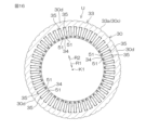
また、前記樹脂部が、前記スロット開口部を塞ぐように前記軸方向に延びる第3部分を含む。このため、冷却液が、スロット内に侵入する場合であって、該冷却液は、スロット開口部を通してエアギャップへ侵入することが抑制される。このため、機械損失の増大が抑制され、効率を高くすることができる。
2 ハウジング
3 ステータ
4 ロータ
5 樹脂部
7 金属リング
7a 外周面
7b 内周面
7c 一端部
13 シール部材
14 シール部材
20 ハウジング本体
21 第1カバーハウジング
21b 筒状壁
21h 外周面
21j 収容溝
22 第2カバーハウジング
22b 筒状壁
22h 外周面
22j 収容溝
23 第1冷却ポート
24 第2冷却ポート
25 冷却液流路
30 ステータコア
30a 第1軸方向端面
30b 第2軸方向端面
31 コイル
31b 第1コイルエンド
31c 第2コイルエンド
33 ヨーク
33b 内周
34 ティース
35 スロット
35a コイル収容部
35b スロット開口部
36 セグメントコイル
36e 傾斜部
36f 傾斜部
36g 傾斜部
36j 接合端部
36k 接合端部
51 閉塞部(第3部分)
51a 一端(軸方向端部)
52 筒状壁(第2部分)
52a 一端(軸方向端部)
52c 当接部
52e 介在部
53 覆い部(第1部分)
54 補強部
55 環状覆い部
56 腕部
AG エアギャップ
H1~H4 最大突出高さ
K1 回転軸線
Q1 第1コイルエンド冷却流路
Q2 第2コイルエンド冷却流路
R1 径方向内方
R2 径方向外方
W1 第1筒状壁
W2 第2筒状壁
X 軸方向
Y 周方向
Claims (10)
- ステータコアとコイルとを含むステータであって、前記ステータコアが、回転軸線に沿う軸方向に延びる軸状且つ前記回転軸線を取り囲む環状のヨークと、前記回転軸線周りの周方向に間隔を空けて前記ヨークの内周に配置された複数のティースと、隣り合うティース間に区画された複数のスロットとを有し、各スロットが、前記コイルを収容するコイル収容部と前記コイル収容部を径方向内方へ開放させるスロット開口部とを有し、前記コイルが、前記ステータコアの軸方向端面から前記軸方向に突出するコイルエンドを有する、ステータと、
前記ステータの径方向内方にエアギャップを介して配置され、前記回転軸線周りに回転可能なロータと、
前記ステータコアと同心に配置される第1筒状壁であって、前記ステータコアの前記軸方向端面に当接する当接部を前記軸方向の一端に有する、第1筒状壁と、
前記ステータと前記ロータとを収容する金属製のハウジングであって、前記第1筒状壁に挿入嵌合される第2筒状壁を含み、前記第1筒状壁および前記第2筒状壁の径方向外方に、前記コイルエンドを冷却する冷却液が流されるコイルエンド冷却流路を区画する、ハウジングと、を含み、
前記第1筒状壁は、前記第2筒状壁の外周面と嵌合される内周面を有する金属リングを含み、
前記ステータコアに一体に形成され、前記金属リングを保持する樹脂部をさらに含み、前記樹脂部が、前記スロット開口部を塞ぐように前記軸方向に延びる部分を含む、電動モータ。 - 前記樹脂部が、前記ステータコアの前記軸方向端面を覆う第1部分と、前記金属リングの外周面の少なくとも一部を覆い前記第1筒状壁の一部を形成する第2部分と、前記スロット開口部を塞ぐように前記軸方向に延びる前記部分である第3部分と、を含む、請求項1に記載の電動モータ。
- 前記金属リングおよび前記第2部分が、前記ステータコアの前記軸方向の両側に一対ずつ配置されており、
前記第3部分が、前記一対の第2部分どうしを連結する、請求項2に記載の電動モータ。 - 前記金属リングが、前記ステータコアの前記軸方向端面に対して前記軸方向に対向する前記軸方向の一端部を含み、
前記金属リングの前記一端部が、前記ステータコアの前記軸方向端面から離隔している、請求項1~3の何れか一項に記載の電動モータ。 - 前記樹脂部が、前記ステータコアの前記軸方向端面と前記金属リングの前記一端部との間に介在する介在部であって、前記第1筒状壁の一部を形成し、前記当接部が設けられる介在部を含む、請求項4に記載の電動モータ。
- 前記コイルが、複数のセグメントコイルによって形成され、
前記ステータコアの前記軸方向端面からの前記軸方向の突出高さに関して、前記コイルエンドの最大突出高さが、前記金属リングの最大突出高さよりも高い、請求項1~5の何れか一項に記載の電動モータ。 - 前記コイルエンドにおいて、前記セグメントコイルが、径方向内方から見て前記軸方向に対して傾斜する傾斜部を含み、
前記ステータコアの前記軸方向端面からの前記軸方向の突出高さに関して、前記傾斜部の最大突出高さが、前記金属リングの最大突出高さよりも高い、請求項6に記載の電動モータ。 - 前記コイルエンドにおいて、前記セグメントコイルが、他のセグメントコイルと接続される接合端部を含み、
前記接合端部が、前記ステータコアの前記軸方向端面からの前記軸方向の突出高さに関して前記金属リングの最大突出高さよりも高い位置に配置される、請求項6または7に記載の電動モータ。 - 前記第2筒状壁の前記外周面に、前記第2筒状壁の前記外周面と前記金属リングの前記内周面との間を封止するシール部材を収容する収容溝が形成されている、請求項1~8の何れか一項に記載の電動モータ。
- 前記コイルエンド冷却流路が、前記冷却液で満たされる、請求項1~9の何れか一項に記載の電動モータ。
Priority Applications (3)
| Application Number | Priority Date | Filing Date | Title |
|---|---|---|---|
| JP2021140478A JP7312794B2 (ja) | 2021-08-30 | 2021-08-30 | 電動モータ |
| US17/889,516 US20230063598A1 (en) | 2021-08-30 | 2022-08-17 | Electric motor |
| EP22192602.5A EP4142122A1 (en) | 2021-08-30 | 2022-08-29 | Electric motor |
Applications Claiming Priority (1)
| Application Number | Priority Date | Filing Date | Title |
|---|---|---|---|
| JP2021140478A JP7312794B2 (ja) | 2021-08-30 | 2021-08-30 | 電動モータ |
Publications (2)
| Publication Number | Publication Date |
|---|---|
| JP2023034311A JP2023034311A (ja) | 2023-03-13 |
| JP7312794B2 true JP7312794B2 (ja) | 2023-07-21 |
Family
ID=83151930
Family Applications (1)
| Application Number | Title | Priority Date | Filing Date |
|---|---|---|---|
| JP2021140478A Active JP7312794B2 (ja) | 2021-08-30 | 2021-08-30 | 電動モータ |
Country Status (3)
| Country | Link |
|---|---|
| US (1) | US20230063598A1 (ja) |
| EP (1) | EP4142122A1 (ja) |
| JP (1) | JP7312794B2 (ja) |
Citations (3)
| Publication number | Priority date | Publication date | Assignee | Title |
|---|---|---|---|---|
| JP2003224945A (ja) | 2002-01-30 | 2003-08-08 | Nissan Motor Co Ltd | 回転電機におけるステータの冷却構造 |
| JP2003244896A (ja) | 2002-02-14 | 2003-08-29 | Meidensha Corp | 水冷式回転機 |
| JP2016220329A (ja) | 2015-05-18 | 2016-12-22 | 東芝三菱電機産業システム株式会社 | 回転電機 |
Family Cites Families (9)
| Publication number | Priority date | Publication date | Assignee | Title |
|---|---|---|---|---|
| JPS59222057A (ja) * | 1983-05-31 | 1984-12-13 | Toshiba Corp | 回転電機 |
| CN1022599C (zh) * | 1989-11-06 | 1993-10-27 | 中国科学院新疆物理研究所 | 交流电机定子圈式线圈的新换位联接 |
| JP2552242Y2 (ja) * | 1991-03-01 | 1997-10-29 | 株式会社前川製作所 | キャンドモータ用キャンの構造 |
| JP2862057B2 (ja) * | 1992-05-14 | 1999-02-24 | 三菱電機株式会社 | 電動ポンプ |
| EP1271747A1 (de) * | 2001-06-27 | 2003-01-02 | E + A Elektromaschinen und Antriebe AG | Statorkühlung im Spaltrohrmotor |
| JP4453934B1 (ja) | 2009-02-20 | 2010-04-21 | 雅枝 毛利 | 抱き寝用枕 |
| KR101475369B1 (ko) * | 2010-12-22 | 2014-12-23 | 가부시키가이샤 아이에이치아이 | 회전기 |
| US20170310189A1 (en) * | 2016-04-25 | 2017-10-26 | Ford Global Technologies, Llc | Stator Cooling For Electric Machines |
| DE102021105759A1 (de) * | 2021-03-10 | 2022-09-15 | Dr. Ing. H.C. F. Porsche Aktiengesellschaft | Spaltrohrmotor |
-
2021
- 2021-08-30 JP JP2021140478A patent/JP7312794B2/ja active Active
-
2022
- 2022-08-17 US US17/889,516 patent/US20230063598A1/en not_active Abandoned
- 2022-08-29 EP EP22192602.5A patent/EP4142122A1/en active Pending
Patent Citations (3)
| Publication number | Priority date | Publication date | Assignee | Title |
|---|---|---|---|---|
| JP2003224945A (ja) | 2002-01-30 | 2003-08-08 | Nissan Motor Co Ltd | 回転電機におけるステータの冷却構造 |
| JP2003244896A (ja) | 2002-02-14 | 2003-08-29 | Meidensha Corp | 水冷式回転機 |
| JP2016220329A (ja) | 2015-05-18 | 2016-12-22 | 東芝三菱電機産業システム株式会社 | 回転電機 |
Also Published As
| Publication number | Publication date |
|---|---|
| EP4142122A1 (en) | 2023-03-01 |
| JP2023034311A (ja) | 2023-03-13 |
| US20230063598A1 (en) | 2023-03-02 |
Similar Documents
| Publication | Publication Date | Title |
|---|---|---|
| US12136858B2 (en) | Axial flux machine | |
| JP7312795B2 (ja) | 電動モータ | |
| JP5772832B2 (ja) | 回転機 | |
| JP7312796B2 (ja) | 電動モータ | |
| CN110957842A (zh) | 旋转电机 | |
| JP7459952B2 (ja) | 回転機械 | |
| JP7724837B2 (ja) | 電動モータ | |
| CN114189091A (zh) | 旋转电机 | |
| JP5270635B2 (ja) | 回転電機の冷却構造 | |
| JP7568563B2 (ja) | 回転電機のステータ | |
| JP2023034311A (ja) | 電動モータ | |
| JP7724838B2 (ja) | 電動モータ | |
| JP7724836B2 (ja) | 電動モータ | |
| JP7633313B2 (ja) | 回転電機用ステータ | |
| CN117803576A (zh) | 泵装置 | |
| JP7578149B2 (ja) | 回転電機の筐体構造 | |
| JP7724839B2 (ja) | 電動モータ | |
| JP7765370B2 (ja) | 回転電機のステータ冷却構造 | |
| WO2024135568A1 (ja) | ステータ | |
| US12253094B2 (en) | Pump device | |
| US12483087B2 (en) | Rotary electrical machine | |
| WO2025022753A1 (ja) | モータ | |
| JP2024005158A (ja) | ポンプ装置 |
Legal Events
| Date | Code | Title | Description |
|---|---|---|---|
| A621 | Written request for application examination |
Free format text: JAPANESE INTERMEDIATE CODE: A621 Effective date: 20220301 |
|
| A131 | Notification of reasons for refusal |
Free format text: JAPANESE INTERMEDIATE CODE: A131 Effective date: 20230209 |
|
| A521 | Request for written amendment filed |
Free format text: JAPANESE INTERMEDIATE CODE: A523 Effective date: 20230406 |
|
| TRDD | Decision of grant or rejection written | ||
| A01 | Written decision to grant a patent or to grant a registration (utility model) |
Free format text: JAPANESE INTERMEDIATE CODE: A01 Effective date: 20230622 |
|
| A61 | First payment of annual fees (during grant procedure) |
Free format text: JAPANESE INTERMEDIATE CODE: A61 Effective date: 20230710 |
|
| R150 | Certificate of patent or registration of utility model |
Ref document number: 7312794 Country of ref document: JP Free format text: JAPANESE INTERMEDIATE CODE: R150 |