JP7328131B2 - Recovery device for long members - Google Patents
Recovery device for long members Download PDFInfo
- Publication number
- JP7328131B2 JP7328131B2 JP2019216542A JP2019216542A JP7328131B2 JP 7328131 B2 JP7328131 B2 JP 7328131B2 JP 2019216542 A JP2019216542 A JP 2019216542A JP 2019216542 A JP2019216542 A JP 2019216542A JP 7328131 B2 JP7328131 B2 JP 7328131B2
- Authority
- JP
- Japan
- Prior art keywords
- long member
- recovery device
- cable
- gears
- power distribution
- Prior art date
- Legal status (The legal status is an assumption and is not a legal conclusion. Google has not performed a legal analysis and makes no representation as to the accuracy of the status listed.)
- Active
Links
Images


Landscapes
- Forwarding And Storing Of Filamentary Material (AREA)
- Electric Cable Installation (AREA)
Description
本発明は、長尺部材の回収装置に関し、さらに詳しくは、地下に埋設された配電ケーブルなどの長尺部材(特に径の太い撚線ケーブル)を地中から引き上げて回収する長尺部材の回収装置に関する。 TECHNICAL FIELD The present invention relates to a long member recovery apparatus, and more particularly, long member recovery for recovering a long member such as a power distribution cable (especially a stranded cable with a large diameter) buried underground from the ground. Regarding the device.
地下に埋設された配電ケーブル、電線その他の長尺部材を撤去する場合にそれらの長尺部材を地中から引き上げて回収する装置が用いられる。そのような回収装置として、例えば、特許文献1に示すケーブル撤去装置がある。特許文献1に示すケーブル撤去装置は、両端から中央に亘って徐々に縮径されていると共にケーブルの長さ方向と直交する方向に多数の歯が形成された左右一対の駆動ローラを水平に所定の距離をもって配置し、左右一対のローラ間に管路から引き出されたケーブルを介在させ、駆動ローラに形成された多数の歯によってケーブルを引き出すものである。この特許文献1には、ケーブルを管路から引き出す力を増大させるためにローラの個数を増やす技術が開示されている。
2. Description of the Related Art When removing long members such as power distribution cables and electric wires buried underground, a device for pulling up and recovering the long members from the ground is used. As such a recovery device, for example, there is a cable removal device disclosed in
また、特許文献2には、前後に配設されたガイド手段及びガイド手段間に設置された一対の引き込み車にケーブルを挿通し、さらに後側のガイド手段の後部に配設された切断具によって引き出されたケーブルを所定長に切断する撤去ケーブル処理装置が開示されている。この特許文献2には、ケーブルが滑動することなく確実に送られるように両引き込みローラの表面に凹凸を形成して抵抗を大きくする技術が開示されている。
Further, in
さらに、特許文献3には、管路から配電ケーブルを引き出しながら切断することのできる回収装置が開示されている。この回収装置には、ウインチワイヤ巻取部と、巻き取り中のワイヤを整列させるワイヤトラバーサと、ウインチワイヤ巻取部によって巻き取られるウインチワイヤをガイドすると共に管路から引き出された長尺部材としての配電ケーブルをガイドするシーブと、配電ケーブルを上下方向から圧接しながらその把持力によって配電ケーブルを後方へ送り出すことにより配電ケーブルを引き込んで管路から引き上げる引き込み部と、引き込み部6によって引き上げられた配電ケーブルを所定の長さに連続的に切断する切断ユニットとが備えられる。この特許文献3には、ピンチローラの表面にギア溝のような凹凸を形成して配電ケーブルをスリップさせることなく確実にグリップする技術が開示されている。
Furthermore,
しかしながら、本発明者等の実験によると、撤去対象が径の太い配電ケーブルである場合には、配電ケーブルを挟持するピンチローラのグリップ力が不足する可能性のあることが判明した。その一方で、一対のピンチローラの間隔を単純に狭めると、ピンチローラを構成する平歯車の歯先が配電ケーブルの被覆の一部へ深く食い込み、これを削がしてしまい、ピンチローラが空回りして配電ケーブルを引き込めなくなることが判明した。 However, according to experiments by the present inventors, it has been found that if the object to be removed is a power distribution cable with a large diameter, the gripping force of the pinch rollers that pinch the power distribution cable may be insufficient. On the other hand, if the gap between a pair of pinch rollers is simply narrowed, the tooth tips of the spur gears that make up the pinch rollers will deeply bite into a portion of the sheathing of the power distribution cable and scrape it off, causing the pinch rollers to idle. It turned out that the power distribution cable could not be retracted due to the
このため、例えばピンチローラに平歯車を用いた従来の回収装置では、配電ケーブルの被覆の剛性の限界から、ピンチローラの間隔を一定以上に狭めることはできず、事実上は1700kgf程度の力でしか配電ケーブルを牽引できなかった。よって、大きな牽引力を要する径の太い配電ケーブルについては、ウインチやラフタークレーンなどで繰り返し引き上げる作業を行うなど、別途の作業を実施せざるを得ず、撤去作業に手間と時間を要していた。 For this reason, for example, in a conventional recovery device using spur gears for pinch rollers, the interval between the pinch rollers cannot be narrowed beyond a certain level due to the rigidity limit of the coating of the power distribution cable, and a force of about 1700 kgf is practically used. They could only tow power distribution cables. Therefore, for large-diameter power distribution cables that require a large pulling force, separate work such as repeated pulling up with a winch or rough terrain crane has to be performed, which requires time and effort for removal work.
本願発明者等が実験を重ねたところ、この問題は、配電ケーブルに採用されている「撚線」という構造に起因して発生しており、特に、撚り合わせた電線の本数が3であって撚線ケーブルの外径が50mm以上である場合に顕著となることが判明した。 As a result of repeated experiments by the inventors of the present application, it was found that this problem was caused by the structure of "twisted wires" used in power distribution cables. It was found that this becomes remarkable when the outer diameter of the stranded cable is 50 mm or more.
そこで、本発明は、かかる問題点に鑑みなされたもので、径の大きい撚線ケーブルをも回収し得る長尺部材の回収装置を提供することを目的とする。 SUMMARY OF THE INVENTION Accordingly, it is an object of the present invention to provide a long member recovery apparatus capable of recovering even a stranded cable having a large diameter.
上記課題を解決するために請求項1に記載の発明は、撚線ケーブル等の巻取り可能な長尺部材を引き込んで回収する長尺部材の回収装置であって、対向するようにして配置された少なくとも一対のローラで前記長尺部材を挟持しつつ引き込む引き込み部を備え、前記一対のローラの少なくとも一方は、回転軸に沿った方向に重ねて配置された複数の歯車を備え、少なくとも一部の隣り合う歯車は、前記長尺部材の表面に対するグリップ力が高まるように、互いの歯先円直径及び歯先の周位置の少なくとも一方に差異が設けられていることを特徴とする。
In order to solve the above problems, the invention according to
上記課題を解決するために請求項2に記載の本発明は、請求項1に記載の長尺部材の回収装置において、前記複数の歯車は、前記長尺部材の外周に沿うように、前記ローラの中央よりも外側に配置された歯車ほど歯先円直径が長く設定されていることを特徴とする。
In order to solve the above-mentioned problems, the present invention according to
上記課題を解決するために請求項3に記載の本発明は、請求項1又は2に記載の長尺部材の回収装置において、前記歯車は、歯先が先細りとなったスプロケット歯車であることを特徴とする。
In order to solve the above-mentioned problems, the present invention according to
上記課題を解決するために請求項4に記載の本発明は、請求項1から3のいずれか1項に記載の長尺部材の回収装置において、前記一対のローラは、前記長尺部材の引き込み方向に沿って複数配置されていることを特徴とする。
In order to solve the above-mentioned problems, the present invention according to
上記課題を解決するために請求項5に記載の本発明は、請求項1から4のいずれか1項に記載の長尺部材の回収装置において、前記引き込み部によって引き込まれた前記長尺部材を巻き取る巻取装置が設けられていることを特徴とする。
In order to solve the above-mentioned problems, the present invention as set forth in
上記課題を解決するために請求項6に記載の本発明は、請求項1から5のいずれか1項に記載の長尺部材の回収装置において、前記引き込み部によって引き込まれた前記長尺部材を所定の長さに切断する切断ユニットが設けられていることを特徴とする。
In order to solve the above-mentioned problems, the present invention as set forth in
本発明の長尺部材の回収装置において、一対のローラの少なくとも一方は、回転軸に沿った方向に重ねて配置された複数の歯車を備え、少なくとも一部の隣り合う前記歯車の間では、前記長尺部材の表面に対するグリップ力が高まるように、歯先円直径及び歯先の周位置の少なくとも一方に差異が設けられているので、引き込み方向のみならず、ローラ表面の引き込み方向に直交する方向にかけても凹凸分布を設けることができる。 In the elongated member collecting apparatus of the present invention, at least one of the pair of rollers has a plurality of gears stacked in a direction along the rotation axis, and between at least some of the adjacent gears, the At least one of the diameter of the tip circle and the circumferential position of the tip is different so that the grip force on the surface of the elongated member is increased. It is also possible to provide unevenness distribution over the area.
ここで、図12(A),(B)に示すとおり長尺部材の一種である撚線ケーブル200は複数の電線200A,200B,200Cを撚り合わせているため、図12(A)に示すとおり引き込み方向にかけて一定の周期で凹部(白矢印)と凸部(黒矢印)とが繰り返し現れるだけでなく、図12(B)の左端に示すとおり周方向にかけても一定の周期で凹部(白矢印)と凸部(黒矢印)とが繰り返し現れる。
Here, as shown in FIGS. 12A and 12B, a stranded
これに対して、平歯車で構成された従来のローラは、撚線ケーブル200の引き込み方向に直交する方向にかけて平坦な形状をしているため、撚線ケーブル200の表面の凹部(白矢印)との間に隙間が生じて接触面積が不足し、グリップ力が不足するという問題が発生していた。
On the other hand, conventional rollers made of spur gears have a flat shape in the direction perpendicular to the direction in which stranded
しかしながら、複数の歯車を重ねた本発明のローラは、引き込み方向に直交する方向にかけても凹凸分布を有しているので、撚線ケーブル200の表面の凹部(白矢印)にまで歯先が届き易くなり、撚線ケーブル200の表面へ同時に接触できる面積が増大してグリップ力が高まるという効果がある。この効果は、特に撚線ケーブル200について顕著であるが、撚線ケーブル200以外の長尺部材(非撚線ケーブルや電線など)についても少なからず得られるものと考えられる。
However, since the roller of the present invention, in which a plurality of gears are superimposed, has an uneven distribution even in the direction perpendicular to the pull-in direction, the tooth tips easily reach even the concave portions (white arrows) on the surface of the stranded
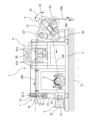
以下、本発明に係る長尺部材の回収装置について、好ましい一実施形態に基づいて詳細に説明する。図1は本発明に係る長尺部材の回収装置の一実施形態の構成を示す正面図である。 BEST MODE FOR CARRYING OUT THE INVENTION Hereinafter, a long member recovery apparatus according to the present invention will be described in detail based on a preferred embodiment. FIG. 1 is a front view showing the configuration of an embodiment of a long member recovery device according to the present invention.
1.回収装置の構成
図1に示された長尺部材の回収装置(以下、単に「回収装置」という)1は、概略として、基台となるベース部2と、ウインチワイヤ100を巻き取るウインチワイヤ巻取部3と、巻き取り中のワイヤ100を整列させるワイヤトラバーサ4と、ウインチワイヤ巻取部3によって巻き取られるウインチワイヤ100をガイドすると共に管路から引き出された長尺部材としての配電ケーブル200をガイドするシーブ5と、配電ケーブル200を上下方向から圧接しながらその把持力によって配電ケーブル200を後方へ送り出すことにより配電ケーブル200を引き込んで管路から引き上げる引き込み部6と、引き込み部6によって引き上げられた(引き込まれた)配電ケーブル200を所定の長さに連続的に切断する切断ユニット7を備えて構成されている。尚、ウインチワイヤ巻取部3、シーブ5、引き込み部6及び切断ユニット7の動作及び停止を操作するための図示しない操作盤を備えている。ここで、切断ユニット7に代えて引き上げた(引き込まれた)配電ケーブル200を図示しないボビンに巻き取る巻取装置を設けることもできる。この場合には、配電ケーブル200を長尺のままボビンに巻き取った状態で回収を行うことができる。配電ケーブル200の切断処理が必要な場合には後処理施設等に搬入して適宜に切断処理を行うことになる。
1. Configuration of Recovery Device A recovery device (hereinafter simply referred to as “recovery device”) 1 for long members shown in FIG. A
回収装置1は、図1に示すように、作業現場の所定の地面FL上に設置することもでき、また、図2に示すように、トラック等の車両300の荷台に搭載することができる。回収装置1を車両300に搭載することにより、現場に移動して配電ケーブル200を管路から引き上げながら切断、回収処理を迅速に行うことができる。尚、油圧ユニット8は、ウインチワイヤ巻取部3、引き込み部6、切断ユニット7等の駆動に用いられる。
The
ウインチワイヤ巻取部3は、ワイヤ100を巻き取るための装置であり、管路に布設されている配電ケーブル200の端部にワイヤ100を取り付けて、そのワイヤ100を巻き取ることにより配電ケーブル200を管路から引き上げて引き込み部6へ案内するために用いられる。ウインチワイヤ巻取部3は、概略として、駆動源となるモータ及び減速機を備えた駆動部31と、回転駆動する駆動部31によりウインチワイヤ100を巻き取る巻取ドラム32と、巻取ドラム32へ巻き取られているウインチワイヤ100をガイドするガイド部33を備えて構成されている。そして、ウインチワイヤ巻取部3の前方にはワイヤトラバーサ4が配置されており、巻取ドラム32に巻き取り中のウインチワイヤ100を水平方向に往復移動するようにして案内することによりウインチワイヤ100が巻取ドラム32に整列して巻き取られる。
The winch
2.引き込み部
図3は、引き込み部の平面図、図4は、引き込み部の正面図、図5は、引き込み部の側面図である。図3~図5に示すとおり、引き込み部6は、少なくとも一方側が回転駆動する一対の搬送部材を備えており、本実施形態では搬送部材として回転部60a,60bにそれぞれ設けられた回転するピンチローラ61a,61bが設けられている。引き込み部6は、ピンチローラ61a,61bで配電ケーブル200を上下方向から圧接し、その把持力によって配電ケーブル200を後方へ送り出すことで配電ケーブル200を引き上げる装置であり、シーブ5と切断ユニット7の間に配置されている。引き込み部6の回転部60aと回転部60bは対称に形成されており、構成は同じであるため回転部60aについて説明する。図3、図4に示すように、回転部60aは、駆動部65と、駆動部65によって回転するギア64と、ギア64に対して対向する位置それぞれ螺合するギア63a,63bと、ギア63a,63bの回転軸に同軸にそれぞれ取り付けられたピンチローラ61a,61bを備えて構成されている。回転部60aを構成するギア63a,63b、ギア64及び駆動部65はフレーム66に保持されている。尚、ピンチローラ61a,61bはいずれか一方のみを駆動可能とすることもできる。ピンチローラ61a,61bは所定の間隔を有して配電ケーブル200の移動方向における前後に配設されており、その表面62にはギア溝のような凹凸が形成され、配電ケーブル200をスリップさせることなく確実にグリップするためのスリップ防止構造とされている(詳細は後述)。
2. Retracting Portion FIG. 3 is a plan view of the retracting portion, FIG. 4 is a front view of the retracting portion, and FIG. 5 is a side view of the retracting portion. As shown in FIGS. 3 to 5, the pull-in
また、ピンチローラ61a,61bは、その間隔が調整可能とされており、これによって多様な配電ケーブル200、例えば径サイズの異なるものや3本縒りされた撚線ケーブル等に対応することができるようになっている。ピンチローラ61a,61bを配電ケーブル200へ押し付けるに際しては窒素ガスを充填したアキュームレータによるクッション機構が用いられる。このようなクッション機構の採用により、配電ケーブル200が3本縒り等の場合であってもピンチローラ61a,61bで確実に送り出すことができる(詳細は後述)。
In addition, the
3.切断ユニット
切断ユニット7は、引き込み部6によって引き込まれた配電ケーブル200を所定の長さに切断する装置である。切断ユニット7は、概略として、図1に示すとおり、引き込み部6から送られてくる配電ケーブル200が挿入される開口部71が設けられたガイド部材70と、ガイド部材70に固定された下向きに半円状の刃を備えた上刃72と、上刃72の内側(即ち、配電ケーブル200の挿入側)に配置されると共に、矩形の板状体の一部を円形にくり抜いた開口の端縁部に切断刃が形成され、且つ、上下動が可能な下刃73と、下刃73を駆動部74の可動部に固定する取付部75と、配電ケーブル200の挿入側の下刃73の上部の開口縁部に沿って取り付けられた押下部材と、上刃72及び下刃73によって切断されたケーブル片を所定位置へ誘導するガイド板76を備えて構成されている。
3. Cutting Unit The
下刃73はピンチローラ61a,61bの駆動状態、即ち搬送状態に連動して昇降駆動される。その昇降駆動は駆動部74によって行われる。具体的には、予め制御回路で設定した配電ケーブル200の所定長が搬送される毎にピンチローラ61a,61bの駆動を停止し、そのタイミングで下刃73を上昇させることにより、開口部71を通過した配電ケーブル200が所定長毎に切断される。尚、下刃73は通常は下側に位置して開口部71と下刃73の開口縁部とが一致する待機位置に位置しており、配電ケーブル200の切断を行うときにのみ駆動部74の駆動により上昇して配電ケーブル200を切断し、切断が完了したら下刃73が下降し、そして待機位置で停止する。この構造により単線からなる配電ケーブル200に限らず3本縒りの撚線ケーブルにも対応可能となっている。
The
配電ケーブル200の切断に際しては、下刃73を上昇させることにより配電ケーブル200を押し上げながら上刃72に食い込ませ、上刃72と下刃73とで切断する動作となる。そのため、配電ケーブル200を切断した後に配電ケーブル200の切断された端部が上刃72に食い込んだ状態となってしまうことがある。そのため、下刃73には配電ケーブル200の挿入側の上部側の開口縁部に沿って押下部材77が取り付けられており、下刃73が下降する際、配電ケーブル200を押し下げて上刃72から離し、配電ケーブルを開口部71へ案内することができるようになっている。本実施形態では押下部材77は断面円弧状をした部材とされているがこれに限定されるものではなく、上刃72に食い込んだ配電ケーブル200を押圧できる形状であればよい。
When the
4.回収装置の動作
次に、各図を参照して回収装置1の動作について説明する。まず、作業者は、ガイド部材52を図1に示すガイド部材52’の位置になるようにアーム51を傾斜させ、図示しない固定ピンによってその位置で固定する。次いで、ウインチワイヤ巻取部3からウインチワイヤ100を引き出し、ワイヤトラバーサ4及びシーブ5のガイド部材52’を経由させて管路内に導き、管路内に布設されている配電ケーブル200の先端部にウインチワイヤ100を結び付ける。次いで、ウインチワイヤ巻取部3を駆動させてウインチワイヤ100の巻き取りを開始する。ウインチワイヤ100はワイヤトラバーサ4によって整列巻が行われるので、ウインチワイヤ100に余計な負荷がかからないため駆動部31の負担を軽減すると共にワイヤ100の寿命も長くすることができる。そして、管路内から引き出された配電ケーブル200の先端が所定の位置まで引き上げられたら、引上げた配電ケーブル200の端末を保持しながらガイド部材52’の位置からガイド部材52’’の位置(図1参照)になるようにアーム51を上方へ回動させて固定した後、配電ケーブル200の先端を引き込み部6へ導く。尚、ピンチローラ61a,61bで配電ケーブル200を挟持して図1の左方向へ送り出す動作を行なう際、初めにガイド部材52のシーブ溝52aに配電ケーブル200を介在させ、次に配電ケーブルがシーブ溝52aによってガイドされるようにピンチローラ61a,61bを操作し、配電ケーブル200の通過経路を確保する。
4. Operation of Recovery Device Next, the operation of the
引き込み部6は、配電ケーブル200の先端を上下一対のピンチローラ61a,61bの間に挿入すると回転する上下一対のピンチローラ61a,61bが配電ケーブル200を上下方向から挟持しながら図1の左方向へ送り出し、切断ユニット7の開口部71に配電ケーブル200を案内する。切断ユニット7では配電ケーブル200の送り量に連動して駆動部74によって下刃73が上昇及び下降を繰り返すことにより配電ケーブル200が予め設定した所定の長さに切断される。切断されたケーブル片は図示しない回収箱等に順次落下して回収される。尚、切断ユニット7の代わりに、図示しないボビンなどの巻取装置を用いることにより、配電ケーブル200を図示しないボビンに巻き取って回収することができる。
In the lead-in
5.ピンチローラの構成の詳細
以下、ピンチローラの構成の詳細について説明する。図1~図5に示したとおり、本実施形態の回収装置1は、撚線ケーブルその他の長尺部材(ここでは、特に撚線ケーブル200を想定する。)を引き込んで回収するものであって、対向するようにして配置された一対のピンチローラ61a,61a及び一対のローラ61b,61bで撚線ケーブル200を挟持しつつ引き込む引き込み部6を備える。ここでは一のピンチローラ61aに着目して説明するが、他のピンチローラも同様の構成であるものとする。
5. Details of Configuration of Pinch Roller Details of the configuration of the pinch roller will be described below. As shown in FIGS. 1 to 5, the
図6は、ピンチローラを構成する複数のスプロケット歯車の概略斜視図、図7は、ピンチローラの概略側面図であり、図7は、ピンチローラの概略側面図である。図6,図7に示すとおり、ピンチローラ61aは、回転軸90に沿った方向に重ねて配置された複数のA形スプロケット歯車61a-1,61a-2,…,61a-8を備える。ここでは、ピンチローラ61aに8枚のスプロケット歯車61a-1~61a-8が重ねて配置される場合を想定する。これら8枚のスプロケット歯車61a-1~61a-8の各々の中央には、回転軸90が嵌合する円孔61Cが設けられており、円孔61Cの周囲には、等間隔で配置された8つのボルト孔61D,61D,…が形成されている。これら8つのボルト孔61D,61D,…にはそれぞれボルト61E,61E,…が挿通され、ボルト61E,61E,…の先端にはナット61F,61F,…が螺合される。これによって、8枚の歯車61a-1~61a-8は、図7に示すとおり隙間なく互いに固定される。なお、図7では、簡単のため、歯先61Bを単純な直線で示している。
6 is a schematic perspective view of a plurality of sprocket gears forming the pinch roller, FIG. 7 is a schematic side view of the pinch roller, and FIG. 7 is a schematic side view of the pinch roller. 6 and 7, the
6.グリップ力を高めるための構造
図7に示すとおり、ピンチローラ61aにおいて、隣り合うスプロケット歯車61a-1,61a-2の間では歯先円直径Rに差異が設けられ、隣り合うスプロケット歯車61a-2,61a-3の間では歯先円直径Rに差異が設けられ、隣り合うスプロケット歯車61a-8,61a-7の間では歯先円直径Rに差異が設けられ、隣り合う歯車61a-7,61a-7の間では歯先円直径Rに差異が設けられている。
6. Structure for Increasing Grip Force As shown in FIG. 7, in the
また、図7に示すとおり、ピンチローラ61aにおいて、全ての隣り合うスプロケット歯車の間では、歯先61Bの周位置にも差異が設けられている。例えば、ピンチローラ61aにおいて、隣り合うスプロケット歯車の間では、歯先61Bの周位置は千鳥配置のように互い違いに設定されている(1/2ピッチずらして配置されている)。なお、隣り合うスプロケット歯車の歯数及び歯先円直径の組み合わせによっては、歯先61Bの周位置を完全な千鳥配置(1/2ピッチずらし)にできない場合もあるが、その場合においても、隣接する歯先61B同士が重ならないようずらして配置することが望ましい。この配置により、ピンチローラ61aの表面62が撚線ケーブル200の被覆表面を横滑りする可能性を軽減できる。
つまり、本実施形態において、ピンチローラ61aを構成する複数のスプロケット歯車61a-1~61a-8のうち少なくとも一部の隣り合うスプロケット歯車は、歯先円直径R及び歯先の周位置の少なくとも一方に差異が設けられており、これによって撚線ケーブル200の表面に対するグリップ力を高めている。
Further, as shown in FIG. 7, in the
That is, in the present embodiment, at least some adjacent sprocket gears among the plurality of sprocket gears 61a-1 to 61a-8 constituting the
7.太いケーブルに対応するための構造
更に、本実施形態では、ピンチローラ61aにおいて、最も外側に位置する2つの歯車61a-1,61a-8は同形同大であり、その内側に配置された2つの歯車61a-2,61a-7は同形同大であり、最も内側に配置された4つの歯車61a-3~61a-6は同形同大に設定される。
7. Structure for coping with thick cable Further, in this embodiment, in the
そして、最も外側に位置する2つの歯車61a-1,61a-8の歯先円直径R1は最も大きく、その内側に配置された2つの歯車61a-2,61a-7の歯先円直径R2は次に大きく、最も内側に配置された4つの歯車61a-3~61a-6の歯先円直径R3は最も小さく設定される。
The two
また、最も外側に位置する2つの歯車61a-1,61a-8の歯数は最も多く、次に内側に配置された2つの歯車61a-2,61a-7の歯数は次に多く、最も内側に配置された4つの歯車61a-3~61a-6の歯数は最も少なく設定される。
The two
すなわち、ピンチローラ61aの中央よりも外側に配置されたスプロケット歯車ほど歯先円直径Rが長く、しかも歯数が多く設定されている。その結果、ピンチローラ61aの表面62は、撚線ケーブル200の外周に沿うような概略凹形状(断面円弧状)となり、しかも、ピンチローラ61aの表面はほぼ均等に微細な凹凸を有することとなる。
That is, the sprocket gears located further outside the center of the
よって、本実施形態の一対のピンチローラ61a,61aは、たとえ撚線ケーブル200の径が太かったとしても、撚線ケーブル200に対する接触面積を大きく確保することができる。そして、ピンチローラ61aの表面を断面円弧状にしたことにより、径の異なる様々な撚線ケーブル200を把持することが可能となっている。
Therefore, the pair of
また、ピンチローラ61aを構成する8枚の歯車61a-1~61a-8の各々は、図6に示すとおり歯先が先細りとなったスプロケット歯車である。図12(A)に示したとおり撚線ケーブル200の表面は引き込み方向にかけて凹凸分布を有しているので、撚線ケーブル200の表面へのピンチローラ61aの接触面積は引き込み中に変動し得るが、本実施形態のように歯車61a-1~61a-8の歯先61Bを尖らせておけば、歯先61Bが深く突き刺さる部分が増えたり、平歯車では届かなかった部分(図12の白矢印)へ浅く突き刺すことができたりするので、撚線ケーブル200に対するグリップ力は高まる。
Each of the eight
さらに、本実施形態の回収装置1では、図1~図4に示したとおり、撚線ケーブル200の引き込み方向に沿って二対のピンチローラ61a,61a,61b,61bが配置されているので、撚線ケーブル200へのピンチローラの総接触面積は2倍となり、グリップ力もその分だけ高まる。
Furthermore, in the
8.実施形態の効果
本実施形態の回収装置1において、ピンチローラ61a,61a,61b,61bの各々は、回転軸90に沿った方向に重ねて配置された複数(8枚)の歯車61a-1~61a-8を備え、少なくとも一部の隣り合う歯車の間では、撚線ケーブル200の被覆表面に対するグリップ力が高まるように、歯先円直径R及び歯先61Bの周位置に差異が設けられているので、ピンチローラ61a,61a,61b,61bの引き込み方向のみならず、引き込み方向に直交する方向にかけても凹凸分布を設けることができる。
8. Effect of Embodiment In the
ここで、図12に示すとおり撚線ケーブル200は複数の電線200A,200B,200Cを撚り合わせているため、図12(A)に示すとおり引き込み方向にかけて一定の周期で凹部(白矢印)と凸部(黒矢印)とが繰り返し現れるだけでなく、図12(B)の左端に示すとおり周方向にかけても一定の周期で凹部(白矢印)と凸部(黒矢印)とが繰り返し現れる。
Here, as shown in FIG. 12, since the stranded
これに対して、平歯車で構成された従来のローラは、撚線ケーブル200の引き込み方向に直交する方向にかけて平坦な形状をしているため、撚線ケーブル200の被覆表面の凹部(白矢印)との間に隙間が生じて接触面積が不足し、グリップ力が不足するという問題が発生していた。
On the other hand, the conventional rollers made of spur gears have a flat shape in the direction perpendicular to the drawing direction of the stranded
しかしながら、適当な形状の8枚の歯車61a-1~61a-8を適当に重ねた本実施形態のピンチローラ61aは、引き込み方向及びこれに直交する方向の双方にかけてそれぞれ適当な凹凸分布を有するので、撚線ケーブル200の被覆表面の凹部(白矢印)にまで歯先61Bが届き、撚線ケーブル200の被覆表面へ同時に接触できる面積が増大してトータルのグリップ力が高まるという効果がある。この効果は、特に撚線ケーブル200について顕著であるが、撚線ケーブル200以外の長尺部材(非撚線ケーブルや電線など)についても少なからず得られるものと考えられる。
However, the
9.実施例
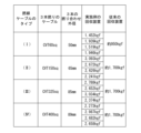
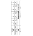
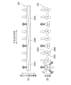
図8は、実施例の回収装置における複数の歯車の仕様を説明する表、図9は、実施例で用いた撚線ケーブルの仕様及び実施例の効果を説明する表、図10は、実施例で用いた撚線ケーブルの材質を説明する断面図である。
9. Examples FIG. 8 is a table explaining the specifications of a plurality of gears in the recovery device of the example, FIG. 9 is a table explaining the specifications of the stranded cable used in the example and the effect of the example, and FIG. FIG. 4 is a cross-sectional view for explaining the material of the stranded cable used in the examples.
図8に示すとおり、本実施例では、ピンチローラ61a,61a,61b,61bの各々に、8枚のスプロケット歯車61a-1~61a-8を用いた。これらのスプロケット歯車としては、機械構造用炭素鋼で構成され、かつ歯先61Bに硬化処理が施されたA形・60番のスプロケット歯車である。
As shown in FIG. 8, in this embodiment, eight sprocket gears 61a-1 to 61a-8 are used for each of the
図9に示すとおり、本実施例では、3本撚りの撚線ケーブル200として、以下の4つのタイプ(I)~(IV)を準備し、これらのタイプ(I)~(IV)それぞれについて回収装置で引き込みの検証を行った。
(I)3本撚りからなる外径50mmの撚線ケーブル(CVT60sq)
(II)3本撚りからなる外径65mmの撚線ケーブル(CVT150sq)
(III)3本撚りからなる外径85mmの撚線ケーブル(CVT325sq)
(IV)3本撚りからなる外径89mmの撚線ケーブル(CVT400sq)
As shown in FIG. 9, in this embodiment, the following four types (I) to (IV) are prepared as the three-stranded stranded
(I) Twisted wire cable (CVT60sq) with an outer diameter of 50 mm consisting of three strands
(II) Twisted wire cable with an outer diameter of 65 mm (CVT 150 sq) consisting of three strands
(III) Twisted wire cable (CVT325sq) with an outer diameter of 85 mm consisting of three strands
(IV) Twisted wire cable (CVT400sq) with an outer diameter of 89 mm consisting of three strands
図10に示すとおり、本実施例では、撚線ケーブル200を構成する3本の電線の各々は、芯部に導体を有し、かつその周囲に内部半導電層、絶縁体(架橋ポリエチレン)、外部半導電層、遮蔽(銅テープ)、バインダ、シース(ビニル)を順に形成したものである。
As shown in FIG. 10, in this embodiment, each of the three electric wires that make up the stranded
図9の1段目に示すとおり、タイプ(I)の撚線ケーブルの引き込みでは、8枚のスプロケット歯車を重ねた本実施例の回収装置によると、1452~1946kgfの牽引力を発揮できたのに対して、1枚の平歯車を使用した従来の回収装置によると、約950kgfの牽引力しか発揮できなかった。 As shown in the first row of FIG. 9, when pulling in a stranded cable of type (I), a pulling force of 1452 to 1946 kgf could be exhibited with the recovery device of this embodiment in which eight sprocket gears were stacked. On the other hand, according to the conventional recovery device using one spur gear, only about 950 kgf of tractive force could be exerted.
図9の2段目に示すとおり、タイプ(II)の撚線ケーブルの引き込みでは、8枚のスプロケット歯車を重ねた本実施例の回収装置によると、2241~3093kgfの牽引力を発揮できたのに対して、1枚の平歯車を使用した従来の回収装置によると約1700kgfの牽引力しか発揮できなかった。 As shown in the second row of FIG. 9, in pulling in a stranded cable of type (II), a pulling force of 2241 to 3093 kgf could be exerted with the recovery device of this embodiment in which eight sprocket gears were stacked. In contrast, the conventional recovery device using a single spur gear could only exert a traction force of about 1700 kgf.
図9の3段目に示すとおり、タイプ(III)の撚線ケーブルの引き込みでは、8枚のスプロケット歯車を重ねた本実施例の回収装置によると、2374~3034kgfの牽引力を発揮できたのに対して、1枚の平歯車を使用した従来の回収装置によると約1700kgfの牽引力しか発揮できなかった。 As shown in the third row of FIG. 9, in pulling in a stranded cable of type (III), a pulling force of 2374 to 3034 kgf could be exerted with the recovery device of this embodiment in which eight sprocket gears were stacked. In contrast, the conventional recovery device using a single spur gear could only exert a traction force of about 1700 kgf.
図9の4段目に示すとおり、タイプ(IV)の撚線ケーブルの引き込みでは、8枚のスプロケット歯車を重ねた本実施例の回収装置によると、2273~2987kgfの牽引力を発揮できたのに対して、1枚の平歯車を使用した従来の回収装置によると約1700kgfの牽引力しか発揮できなかった。 As shown in the 4th row of FIG. 9, when pulling in a stranded cable of type (IV), a pulling force of 2273 to 2987 kgf could be exerted with the recovery device of this embodiment in which eight sprocket gears were stacked. In contrast, the conventional recovery device using a single spur gear could only exert a traction force of about 1700 kgf.
なお、本実施例の回収装置と従来の回収装置との間では、ピンチローラ以外の条件は同じである。 Conditions other than the pinch rollers are the same between the collecting device of this embodiment and the conventional collecting device.
従って、本実施例の回収装置によれば、従来の回収装置の1.5倍超の牽引力を発揮することができ、ロングスパン撚線ケーブル、大径撚線ケーブルの撤去工事にも適用が可能である。因みに、従来の回収装置は、ロングスパン撚線ケーブル、大径撚線ケーブルの引き込みができなかったので、ウインチやラフタークレーンなどで繰り返し引き上げる作業を行うなど、別途の工程を採用せざるを得なかったが、本実施例の回収装置は、ロングスパン撚線ケーブル、大径撚線ケーブルであっても引き込みが可能であるので、撤去工事の作業時間を大幅に削減することができる。また、本実施例の回収装置はグリップ力が高いので、屋外工事における雨等でのスリップの防止効果も期待できる。 Therefore, according to the recovery device of the present embodiment, it is possible to exert a pulling force more than 1.5 times that of the conventional recovery device, and it can be applied to the removal work of long-span stranded cables and large-diameter stranded cables. is. By the way, the conventional recovery equipment could not pull in long-span stranded cables and large-diameter stranded cables, so we had to adopt a separate process, such as repeatedly pulling up with a winch or rough terrain crane. However, since the recovery device of this embodiment can pull in even long-span stranded cables and large-diameter stranded cables, it is possible to greatly reduce the working hours for removal work. In addition, since the recovery device of this embodiment has a high gripping force, it can be expected to prevent slippage due to rain or the like during outdoor construction.
10.変形例
10-1.スプロケット歯車の枚数
上述した実施形態では、個々のピンチローラを構成するスプロケット歯車の枚数を「8」としたが、8に限定されることはなく、2~7又は9以上としてもよい。歯車の枚数は、要求仕様(最大ケーブル径サイズ)に応じて決定されることが望ましい。因みに、図11は、スプロケット歯車の枚数を「7」とした場合の例である。この例においても7枚のスプロケット歯車は回転軸90に沿った方向に重ねて配置され、このうち隣り合うスプロケット歯車(一方端から数えて1番目と2番目、2番目と3番目、5番目と6番目、6番目と7番目)の間では、撚線ケーブル200の被覆表面に対するグリップ力が高まるように、歯先円直径に差異が設けられている。また、このピンチローラにおいて全ての隣り合うスプロケット歯車の間では歯先の周位置に差異が設けられている。また、撚線ケーブル200の外周に沿うように、外側のスプロケット歯車ほど歯先円直径が長く設定されている。
10. Modification 10-1. Number of Sprocket Gears In the above-described embodiment, the number of sprocket gears constituting each pinch roller is "8", but the number is not limited to 8, and may be 2 to 7 or 9 or more. The number of gears is desirably determined according to the required specifications (maximum cable diameter size). Incidentally, FIG. 11 shows an example in which the number of sprocket gears is "7". In this example as well, the seven sprocket gears are stacked in the direction along the
なお、上述した実施形態又は実施例において、各スプロケット歯車の歯数と歯先円直径とは比例関係に設定されることが望ましい。また、各スプロケット歯車の歯数及び歯先円直径は、撚線ケーブル200の引き込み速度と牽引力との組み合わせに応じて選定されることが望ましい。また、個々のピンチローラにおける外側から内側への歯数差は、要求仕様(最大ケーブル径サイズ)に応じて設定されることが望ましい。
In the embodiment or example described above, it is desirable that the number of teeth of each sprocket gear and the diameter of the addendum circle be set in a proportional relationship. Moreover, it is desirable that the number of teeth and the diameter of the addendum circle of each sprocket gear be selected according to the combination of the pull-in speed of the stranded
10-2.被覆の材質
上記実施例では、撚線ケーブル200の被覆の材質としてビニルシースを使用したが、ポリエチレンシースを用いることもできる。
10-2. Coating Material In the above embodiment, a vinyl sheath is used as the coating material of the stranded
10-3.撚線ケーブルのタイプ
上記実施例では、上記4つのタイプ(I)~(IV)の撚線ケーブル200を用いたが、本実施形態又は本実施例の回収装置は、これら4つのタイプ(I)~(IV)以外のケーブルや電線の回収に用いることも可能である。例えば、6600V CVT22sq,CVT38sq,CVT60sq,CVT100sq,CVT150sq,CVT200sq,CVT250sq,CVT325sq,CVT400sq,CVT500sqの各タイプのケーブル又は電線の撤去工事に適用可能である。
因みに、従来の回収装置は、CVT400sq,CVT500sqのケーブル撤去工事に適用できなかったが、本実施形態又は本実施例の回収装置は、CVT400sq,CVT500sqのケーブル撤去工事にも適用可能である。
また、上記実施例では、3本撚りの撚線ケーブル(CVT(triplex))を対象としたが、4本撚りの撚線ケーブル(CVQ(quadruple))や電線の撤去工事にも本実施形態又は本実施形態の回収装置を適用可能である。
10-3. Types of Twisted Cables In the above examples, the stranded
By the way, the conventional recovery device could not be applied to the cable removal work of CVT400sq and CVT500sq, but the recovery device of this embodiment or the present embodiment is applicable to the cable removal work of CVT400sq and CVT500sq.
In addition, in the above embodiment, a three-twisted stranded cable (CVT (triplex)) was targeted, but this embodiment or a wire removal work can also be applied to a four-twisted stranded cable (CVQ (quadruple)) or electric wires. The recovery device of this embodiment can be applied.
10-4.ケーブル等の変更
上述した本実施形態又は実施例の回収装置は、様々な撚線ケーブル、様々な長尺部材(ケーブル又は電線)を回収することが可能である。回収装置が回収すべき長尺部材の種類(被覆の硬さ)や太さが変更された場合には、回収装置を一旦停止して、ケーブルを挟持する一対のピンチローラの間隙を最適値に設定しなおせばよく、基本的にはピンチローラを構成する複数の歯車を付け替える必要はない。一対のピンチローラの間隙は、油圧シリンダにより適度な圧力で長尺部材を挟持できるよう常に最適な間隔に設定されるからである。但し、回収すべき長尺部材の太さや材質が大幅に変更される場合にピンチローラを構成するスプロケット歯車の枚数や組み合わせを変更できるように回収装置を構成してもよいことは言うまでもない。
10-4. Modification of Cables, etc. The recovery device of the present embodiment or example described above is capable of recovering various stranded cables and various long members (cables or electric wires). When the type (coating hardness) or thickness of the long member to be recovered by the recovery device is changed, the recovery device is temporarily stopped and the gap between the pair of pinch rollers that sandwich the cable is adjusted to the optimum value. All you have to do is set it again, and basically there is no need to replace the multiple gears that make up the pinch rollers. This is because the gap between the pair of pinch rollers is always set to an optimum gap so that the long member can be pinched with an appropriate pressure by the hydraulic cylinder. However, it goes without saying that the collection device may be configured so that the number and combination of sprocket gears constituting the pinch rollers can be changed when the thickness and material of the long members to be collected are changed significantly.
10-5.その他
以上のように、本発明の好ましい実施形態について詳述したが、本発明は係る特定の実施形態に限定されるものではなく、特許請求の範囲に記載された本発明の要旨の範囲内において、種々の変形・変更が可能であることはいうまでもない。長尺部材は撚線ケーブルや電線などの配電ケーブルとしたがワイヤ、光ファイバケーブル等であってもよく、可撓性及び或る一定以上の長さを有するものであればよい。また、スプロケット歯車を用いる代わりに、歯先が先細りとなった別の歯車を使用してもよい。
10-5. Others As described above, preferred embodiments of the present invention have been described in detail. , it goes without saying that various modifications and changes are possible. Although the elongated member is a power distribution cable such as a stranded cable or an electric wire, it may be a wire, an optical fiber cable, or the like, as long as it has flexibility and a certain length or more. Also, instead of using a sprocket gear, another gear with a tapered tip may be used.
1 回収装置
2 ベース部
3 ウインチワイヤ巻取部
4 ワイヤトラバーサ
5 シーブ
6 引き込み部
7 切断ユニット
31 駆動部
32 巻取ドラム
33 ガイド部
50 支軸
51 アーム
52 ガイド部材
52a シーブ溝
53 軸
54 調整ボルト
60 ガイド部材
60a,60b 回転部
61a,61b ピンチローラ
62 表面
63a,63b ギア
64 ギア
65 駆動部
66 フレーム
70 ガイド部材
71 開口部
72 上刃
73 下刃
74 駆動部
75 取付部
76 ガイド板
77 押下部材
100 ウインチワイヤ
200 配電ケーブル、撚線ケーブル、長尺部材)
200A 電線
200B 電線
200C 電線
300 車両
61a-1 スプロケット歯車
61a-2 スプロケット歯車
61a-3 スプロケット歯車
61a-4 スプロケット歯車
61a-5 スプロケット歯車
61a-6 スプロケット歯車
61a-7 スプロケット歯車
61a-8 スプロケット歯車
61C 円孔
61D ボルト孔
61E ボルト
61F ナット
90 回転軸
REFERENCE SIGNS
Claims (6)
対向するようにして配置された少なくとも一対のローラで前記長尺部材を挟持しつつ引き込む引き込み部を備え、
前記一対のローラの少なくとも一方は、回転軸に沿った方向に重ねて配置された複数の歯車を備え、少なくとも一部の隣り合う歯車は、前記長尺部材の表面に対するグリップ力が高まるように、互いの歯先円直径及び歯先の周位置の少なくとも一方に差異が設けられていることを特徴とする長尺部材の回収装置。 A long member recovery device for pulling in and recovering a windable long member such as a stranded cable,
At least a pair of rollers arranged to face each other is provided with a retracting portion that retracts the elongated member while sandwiching it,
At least one of the pair of rollers comprises a plurality of gears arranged one above the other in a direction along the rotation axis, and at least some of the adjacent gears are arranged so as to increase the grip force on the surface of the elongated member, A recovering device for a long member, characterized in that at least one of tip circle diameters and tip circumferential positions is different from each other.
前記複数の歯車は、前記長尺部材の外周に沿うように、前記ローラの中央よりも外側に配置された歯車ほど歯先円直径が長く設定されていることを特徴とする長尺部材の回収装置。 In the recovery device for long members according to claim 1,
In the plurality of gears, the diameter of the addendum circle is set to be longer for the gears arranged outside the center of the roller so as to follow the outer circumference of the elongated member. Device.
前記歯車は、歯先が先細りとなったスプロケット歯車である
ことを特徴とする長尺部材の回収装置。 3. In the long member recovery device according to claim 1 or 2,
The long member recovery device, wherein the gear is a sprocket gear with a tapered tooth tip.
前記一対のローラは、前記長尺部材の引き込み方向に沿って複数配置されていることを特徴とする長尺部材の回収装置。 In the long member recovery device according to any one of claims 1 to 3,
The long member collecting device, wherein the pair of rollers is arranged in plurality along the pulling direction of the long member.
前記引き込み部によって引き込まれた前記長尺部材を巻き取る巻取装置が設けられていることを特徴とする長尺部材の回収装置。 In the long member recovery device according to any one of claims 1 to 4,
A long member recovery device, comprising a winding device for winding up the long member pulled in by the pull-in section.
前記引き込み部によって引き込まれた前記長尺部材を所定の長さに切断する切断ユニットが設けられていることを特徴とする長尺部材の回収装置。 In the long member recovery device according to any one of claims 1 to 5,
A long member recovery device, comprising a cutting unit that cuts the long member pulled in by the pull-in section into a predetermined length.
Priority Applications (1)
| Application Number | Priority Date | Filing Date | Title |
|---|---|---|---|
| JP2019216542A JP7328131B2 (en) | 2019-11-29 | 2019-11-29 | Recovery device for long members |
Applications Claiming Priority (1)
| Application Number | Priority Date | Filing Date | Title |
|---|---|---|---|
| JP2019216542A JP7328131B2 (en) | 2019-11-29 | 2019-11-29 | Recovery device for long members |
Publications (2)
| Publication Number | Publication Date |
|---|---|
| JP2021087332A JP2021087332A (en) | 2021-06-03 |
| JP7328131B2 true JP7328131B2 (en) | 2023-08-16 |
Family
ID=76085976
Family Applications (1)
| Application Number | Title | Priority Date | Filing Date |
|---|---|---|---|
| JP2019216542A Active JP7328131B2 (en) | 2019-11-29 | 2019-11-29 | Recovery device for long members |
Country Status (1)
| Country | Link |
|---|---|
| JP (1) | JP7328131B2 (en) |
Families Citing this family (1)
| Publication number | Priority date | Publication date | Assignee | Title |
|---|---|---|---|---|
| CN116914618B (en) * | 2023-07-27 | 2024-02-02 | 哈沈线缆制造有限公司 | End face-flattened cutting device for cable processing |
Citations (3)
| Publication number | Priority date | Publication date | Assignee | Title |
|---|---|---|---|---|
| JP2000355462A (en) | 1999-06-14 | 2000-12-26 | Kodera Electronics Co Ltd | Wire material carrying roller |
| JP2018133937A (en) | 2017-02-16 | 2018-08-23 | 北日本電線株式会社 | Long member recovery system |
| JP2019188422A (en) | 2018-04-23 | 2019-10-31 | 株式会社ジェイピーシー | Machining chip compressor |
Family Cites Families (6)
| Publication number | Priority date | Publication date | Assignee | Title |
|---|---|---|---|---|
| JPS5149388Y2 (en) * | 1973-07-16 | 1976-11-29 | ||
| JPH0635620Y2 (en) * | 1988-12-20 | 1994-09-14 | 日本電信電話株式会社 | Cable towing device |
| JPH0823613A (en) * | 1994-07-04 | 1996-01-23 | Hiroshima Kensetsu Kogyo Kk | Cable cutter |
| JP2965286B2 (en) * | 1996-09-02 | 1999-10-18 | 株式会社トーエネック | Cable laying and / or removing device |
| JP2001070816A (en) * | 1999-09-07 | 2001-03-21 | Matsushita Electric Ind Co Ltd | Board crusher, board recycling system and gypsum board recycling method |
| JP6518226B2 (en) * | 2016-12-02 | 2019-05-22 | 株式会社きんでん | Cable feeding device |
-
2019
- 2019-11-29 JP JP2019216542A patent/JP7328131B2/en active Active
Patent Citations (3)
| Publication number | Priority date | Publication date | Assignee | Title |
|---|---|---|---|---|
| JP2000355462A (en) | 1999-06-14 | 2000-12-26 | Kodera Electronics Co Ltd | Wire material carrying roller |
| JP2018133937A (en) | 2017-02-16 | 2018-08-23 | 北日本電線株式会社 | Long member recovery system |
| JP2019188422A (en) | 2018-04-23 | 2019-10-31 | 株式会社ジェイピーシー | Machining chip compressor |
Also Published As
| Publication number | Publication date |
|---|---|
| JP2021087332A (en) | 2021-06-03 |
Similar Documents
| Publication | Publication Date | Title |
|---|---|---|
| EP0540893B1 (en) | Stranding machine for cables, particularly of larger diameter with alternating twist direction | |
| EP0423443B1 (en) | Process and device for carrying-out the process to feed a cable into a cable manufacturing automaton | |
| CN112103842B (en) | A cable laying device for cable trenches | |
| CN110745649B (en) | Cable paying-off equipment | |
| JP7328131B2 (en) | Recovery device for long members | |
| US6357688B1 (en) | Coiling device | |
| EP0790210B1 (en) | Device for taking up and paying out flexible elastic strand materials | |
| CN1871399A (en) | Method and device for manufacturing a wire cord | |
| US20050211044A1 (en) | Spooling apparatus | |
| JP3248893B2 (en) | Cable multi-drawing method | |
| JP6374545B1 (en) | Long member recovery device | |
| DE3023507C2 (en) | ||
| CN212634135U (en) | Straightening mechanism on coil forming device | |
| JP3228325B2 (en) | Cable multi-drawing method and cable drawing machine | |
| CN205069232U (en) | Stranding machine and many lines pull after -combustion device thereof | |
| US3225798A (en) | Means for processing stone sawing wires | |
| JP2964130B2 (en) | Transmission line removal / recovery device and transmission line winding device | |
| CN213140906U (en) | Quick laying device of cable | |
| CN220264677U (en) | Wear-resistant and drag-resistant pay-off rack for processing shielded cable | |
| CN218828797U (en) | Electric wire and cable laying device | |
| CN220591406U (en) | Processing technique equipment for prestressed steel strand finished product bundle | |
| CN121516665B (en) | A cable reel cart with cable-assisted guidance mechanism and cable reel cart | |
| JPH082813A (en) | PC steel stranded wire feeding device and feeding method | |
| CN118387697B (en) | Cable wire laying treatment device and laying method thereof | |
| CN118513375A (en) | Traction equipment |
Legal Events
| Date | Code | Title | Description |
|---|---|---|---|
| A521 | Request for written amendment filed |
Free format text: JAPANESE INTERMEDIATE CODE: A523 Effective date: 20210128 |
|
| A621 | Written request for application examination |
Free format text: JAPANESE INTERMEDIATE CODE: A621 Effective date: 20220701 |
|
| A977 | Report on retrieval |
Free format text: JAPANESE INTERMEDIATE CODE: A971007 Effective date: 20230222 |
|
| A131 | Notification of reasons for refusal |
Free format text: JAPANESE INTERMEDIATE CODE: A131 Effective date: 20230328 |
|
| A521 | Request for written amendment filed |
Free format text: JAPANESE INTERMEDIATE CODE: A523 Effective date: 20230412 |
|
| TRDD | Decision of grant or rejection written | ||
| A01 | Written decision to grant a patent or to grant a registration (utility model) |
Free format text: JAPANESE INTERMEDIATE CODE: A01 Effective date: 20230725 |
|
| A61 | First payment of annual fees (during grant procedure) |
Free format text: JAPANESE INTERMEDIATE CODE: A61 Effective date: 20230803 |
|
| R150 | Certificate of patent or registration of utility model |
Ref document number: 7328131 Country of ref document: JP Free format text: JAPANESE INTERMEDIATE CODE: R150 |