JP7342000B2 - Lens curvature variable device - Google Patents
Lens curvature variable device Download PDFInfo
- Publication number
- JP7342000B2 JP7342000B2 JP2020531002A JP2020531002A JP7342000B2 JP 7342000 B2 JP7342000 B2 JP 7342000B2 JP 2020531002 A JP2020531002 A JP 2020531002A JP 2020531002 A JP2020531002 A JP 2020531002A JP 7342000 B2 JP7342000 B2 JP 7342000B2
- Authority
- JP
- Japan
- Prior art keywords
- curvature
- lens
- variable
- liquid
- electrode
- Prior art date
- Legal status (The legal status is an assumption and is not a legal conclusion. Google has not performed a legal analysis and makes no representation as to the accuracy of the status listed.)
- Active
Links
Images


Classifications
-
- G—PHYSICS
- G02—OPTICS
- G02B—OPTICAL ELEMENTS, SYSTEMS OR APPARATUS
- G02B26/00—Optical devices or arrangements for the control of light using movable or deformable optical elements
- G02B26/004—Optical devices or arrangements for the control of light using movable or deformable optical elements based on a displacement or a deformation of a fluid
-
- G—PHYSICS
- G02—OPTICS
- G02B—OPTICAL ELEMENTS, SYSTEMS OR APPARATUS
- G02B7/00—Mountings, adjusting means, or light-tight connections, for optical elements
- G02B7/02—Mountings, adjusting means, or light-tight connections, for optical elements for lenses
- G02B7/04—Mountings, adjusting means, or light-tight connections, for optical elements for lenses with mechanism for focusing or varying magnification
- G02B7/08—Mountings, adjusting means, or light-tight connections, for optical elements for lenses with mechanism for focusing or varying magnification adapted to co-operate with a remote control mechanism
-
- G—PHYSICS
- G02—OPTICS
- G02B—OPTICAL ELEMENTS, SYSTEMS OR APPARATUS
- G02B26/00—Optical devices or arrangements for the control of light using movable or deformable optical elements
- G02B26/004—Optical devices or arrangements for the control of light using movable or deformable optical elements based on a displacement or a deformation of a fluid
- G02B26/005—Optical devices or arrangements for the control of light using movable or deformable optical elements based on a displacement or a deformation of a fluid based on electrowetting
-
- G—PHYSICS
- G02—OPTICS
- G02B—OPTICAL ELEMENTS, SYSTEMS OR APPARATUS
- G02B3/00—Simple or compound lenses
- G02B3/12—Fluid-filled or evacuated lenses
-
- G—PHYSICS
- G02—OPTICS
- G02B—OPTICAL ELEMENTS, SYSTEMS OR APPARATUS
- G02B3/00—Simple or compound lenses
- G02B3/12—Fluid-filled or evacuated lenses
- G02B3/14—Fluid-filled or evacuated lenses of variable focal length
-
- G—PHYSICS
- G03—PHOTOGRAPHY; CINEMATOGRAPHY; ANALOGOUS TECHNIQUES USING WAVES OTHER THAN OPTICAL WAVES; ELECTROGRAPHY; HOLOGRAPHY
- G03B—APPARATUS OR ARRANGEMENTS FOR TAKING PHOTOGRAPHS OR FOR PROJECTING OR VIEWING THEM; APPARATUS OR ARRANGEMENTS EMPLOYING ANALOGOUS TECHNIQUES USING WAVES OTHER THAN OPTICAL WAVES; ACCESSORIES THEREFOR
- G03B13/00—Viewfinders; Focusing aids for cameras; Means for focusing for cameras; Autofocus systems for cameras
- G03B13/32—Means for focusing
- G03B13/34—Power focusing
Landscapes
- Physics & Mathematics (AREA)
- General Physics & Mathematics (AREA)
- Optics & Photonics (AREA)
- Mechanical Light Control Or Optical Switches (AREA)
- Automatic Focus Adjustment (AREA)
- Studio Devices (AREA)
- Lens Barrels (AREA)
- Engineering & Computer Science (AREA)
- Multimedia (AREA)
- Signal Processing (AREA)
- Liquid Crystal (AREA)
- Lenses (AREA)
Description
本発明は、レンズ曲率可変装置に関するものであり、より詳しくは迅速かつ正確にレンズの曲率を感知できるレンズ曲率可変装置に関するものである。 The present invention relates to a variable lens curvature device, and more particularly to a variable lens curvature device that can quickly and accurately sense the curvature of a lens.
レンズは、光の経路を変換する装置である。レンズは、多様な電子機器に用いられ、特に、カメラに用いられる。 A lens is a device that changes the path of light. Lenses are used in a variety of electronic devices, particularly cameras.
カメラ内のレンズを通過した光は、イメージセンサを通じて電気信号に変換され、変換された電気信号に基づいてイメージが獲得される。 Light passing through a lens in the camera is converted into an electrical signal through an image sensor, and an image is acquired based on the converted electrical signal.
一方、撮影イメージの焦点を調節するために、レンズの位置を可変することが必要である。しかし、カメラが小型の電子機器に用いられる場合、レンズの位置を可変するために、相当な空間が確保される必要がある不都合がある。 On the other hand, in order to adjust the focus of the captured image, it is necessary to vary the position of the lens. However, when the camera is used in a small electronic device, there is an inconvenience that a considerable amount of space must be secured in order to change the position of the lens.
そこで、撮影イメージの焦点を調節するために、レンズの位置を可変ではなく、他の方案が研究されている。 Therefore, in order to adjust the focus of a captured image, other methods than changing the position of the lens are being researched.
本発明の目的は、迅速かつ正確にレンズの曲率を感知できるレンズ曲率可変装置を提供することにある。 An object of the present invention is to provide a lens curvature variable device that can quickly and accurately sense the curvature of a lens.
本発明の別の目的は、迅速かつ正確にレンズの曲率を可変できるレンズレンズ曲率可変装置を提供することにある。 Another object of the present invention is to provide a lens curvature variable device that can quickly and accurately vary the curvature of a lens.
上記目的を達成するための本発明の一実施例に係るレンズ曲率可変装置は、印加される電気信号に基づいて曲率が可変する液体レンズの曲率を可変するためのレンズ曲率可変装置として、液体レンズに電気信号を印加するレンズ駆動部と、電気信号に基づいて形成された液体レンズの曲率を感知するためのセンサ部と、感知された曲率に基づいて、液体レンズの目標曲率を形成するようにレンズ駆動部を制御する制御部とを含み、センサ部は、液体レンズ内の電極上の絶縁体と電気伝導性水溶液の間の境界領域の面積の大きさまたは面積の変化を感知する。 A lens curvature variable device according to an embodiment of the present invention for achieving the above object is used as a lens curvature variable device for changing the curvature of a liquid lens whose curvature is variable based on an applied electric signal. a lens driving section for applying an electric signal to the lens; a sensor section for sensing the curvature of the liquid lens formed based on the electric signal; and a sensor section for forming a target curvature of the liquid lens based on the sensed curvature. and a control section that controls the lens driving section, and the sensor section senses the size or change in area of the boundary region between the insulator on the electrode in the liquid lens and the electrically conductive aqueous solution.
本発明の一実施例に係るレンズ曲率可変装置は、印加される電気信号に基づいて曲率が可変する液体レンズの曲率を可変するためのレンズ曲率可変装置として、液体レンズに電気信号を印加するレンズ駆動部と、電気信号に基づいて形成された液体レンズの曲率を感知するためのセンサ部と、感知された曲率に基づいて、液体レンズの目標曲率を形成するようにレンズ駆動部を制御する制御部とを含み、センサ部は、液体レンズ内の電極上の絶縁体と電気伝導性水溶液の間の境界領域の面積の大きさまたは面積の変化を感知することで、迅速かつ正確にレンズの曲率を感知できるようになる。 A lens curvature variable device according to an embodiment of the present invention is a lens curvature variable device for varying the curvature of a liquid lens whose curvature is variable based on an applied electric signal. a driving section; a sensor section for sensing the curvature of the liquid lens formed based on an electrical signal; and a control for controlling the lens driving section to form a target curvature of the liquid lens based on the sensed curvature. The sensor unit quickly and accurately determines the curvature of the lens by sensing the size or change in area of the boundary region between the insulator on the electrode and the electrically conductive aqueous solution in the liquid lens. becomes able to sense.
特に、液体レンズ内の電極上の絶縁体と電気伝導性水溶液の間の境界領域の面積の大きさまたは面積の変化に対応するキャパシタンスを感知することで、レンズの曲率を正確に検出できるようになる。 In particular, the curvature of the lens can be accurately detected by sensing the capacitance corresponding to the size or change in area of the interface region between the insulator on the electrode and the electrically conductive aqueous solution in the liquid lens. Become.
一方、センサ部は、液体レンズ内の電極上の絶縁体と電気伝導性水溶液の間の境界領域の面積の大きさまたは面積の変化に対応するキャパシタンスを感知することができ、これをフィードバックして、レンズの曲率が可変するように液体レンズに電気信号を印加することで、迅速かつ正確にレンズの曲率を可変できるようになる。 On the other hand, the sensor unit can sense the size of the area of the boundary region between the insulator on the electrode in the liquid lens and the electrically conductive aqueous solution, or the capacitance corresponding to the change in area, and feedback this. By applying an electrical signal to the liquid lens so as to change the curvature of the lens, the curvature of the lens can be changed quickly and accurately.
一方、レンズ駆動部から出力される複数の電気信号を液体レンズに供給する複数の導電性ラインと、複数の導電性ラインのうちいずれか1つとセンサ部の間に配置されるスイッチング素子とを含み、センサ部が、スイッチング素子のオン期間の間、液体レンズ内の電極上の絶縁体と電気伝導性水溶液の間の境界領域の面積の大きさまたは面積の変化を感知することで、容易にレンズの曲率を感知できるようになる。 On the other hand, it includes a plurality of conductive lines that supply a plurality of electrical signals output from the lens driving section to the liquid lens, and a switching element disposed between any one of the plurality of conductive lines and the sensor section. During the ON period of the switching element, the sensor section senses the size or change in the area of the boundary region between the insulator on the electrode in the liquid lens and the electrically conductive aqueous solution, so that the lens can be easily removed. Be able to sense the curvature of.
一方、演算された曲率と目標曲率に基づいて、曲率エラーを演算するイコライザーと、演算された曲率エラーに基づいて、パルス幅可変信号を生成して出力するパルス幅可変制御部とを含むことで、迅速かつ正確にレンズの曲率を感知できるようになる。 On the other hand, by including an equalizer that calculates a curvature error based on the calculated curvature and the target curvature, and a pulse width variable control section that generates and outputs a variable pulse width signal based on the calculated curvature error, , the curvature of the lens can be sensed quickly and accurately.
一方、レンズ曲率可変装置内の制御部は、イメージ処理部からの焦点情報と、ジャイロセンサからのブレ情報を受信し、焦点情報とブレ情報に基づいて、目標曲率を決定することができ、これによって、ブレに対応して、焦点が合わせられたイメージを獲得できるようになる。 On the other hand, the control unit in the variable lens curvature device receives focus information from the image processing unit and blur information from the gyro sensor, and can determine the target curvature based on the focus information and blur information. This makes it possible to deal with blur and obtain a focused image.
以下、図面を参照して本発明をより詳しく説明する。 Hereinafter, the present invention will be explained in more detail with reference to the drawings.
以下の説明で用いられる構成要素に対する接尾辞「モジュール」および「部」は、単純に本明細書の作成が容易となるように付与されるものとして、それ自体で特に重要な意味または役割を付与するものではない。よって、上記「モジュール」および「部」は、相互混用して用いられることもある。 The suffixes "module" and "part" used in the following explanations are simply added to facilitate the preparation of this specification, and by themselves have particularly important meanings or roles. It's not something you do. Therefore, the above-mentioned "module" and "section" may be used interchangeably.
図1aは、本発明の実施例に係るカメラの内部断面図である。 FIG. 1a is an internal cross-sectional view of a camera according to an embodiment of the invention.
まず、図1aは、カメラ195に対する断面図の一例である。
First, FIG. 1a is an example of a cross-sectional view of the
カメラ195は、絞り194、レンズ193、イメージセンサ820を含むことができる。
絞り194は、レンズ193に入射する光を開閉することができる。
The
イメージセンサ820は、RGBをセンシングするために、RGBフィルター910と、光信号を電気信号に変換するセンサアレイ911を含むことができる。
The
これによって、イメージセンサ820は、RGBイメージをセンシングして、出力することができる。
Accordingly, the
図1bは、図1aのカメラの内部ブロック図である。 FIG. 1b is an internal block diagram of the camera of FIG. 1a.
図面を参照すると、カメラ195は、レンズ193と、イメージセンサ820と、イメージプロセッサ830を含むことができる。
Referring to the drawings,
イメージプロセッサ830は、イメージセンサ820からの電気信号に基づいて、RGBイメージを生成することができる。
一方、イメージセンサ820は、電気信号に基づいて、露出時間が調節される。
Meanwhile, the exposure time of the
図2は、レンズの駆動方式を説明する図面である。 FIG. 2 is a diagram illustrating a lens driving method.
まず、図2の(a)は、焦点位置401からの光が、レンズ403、ビームスプリッタ405、マイクロレンズ407およびイメージセンサ409に伝達されて、イメージセンサ409にFa大きさの相PHができることを示す。
First, (a) in FIG. 2 shows that light from the
特に、図2の(a)は、焦点位置401に対応して、焦点が正確に合わせられたことを例示する。
In particular, FIG. 2A illustrates that the focus is accurately set, corresponding to the
次に、図2の(b)は、図2の(a)に比べて、レンズ403の位置が、焦点位置401の方向に移動して、イメージセンサ409にFaより小さい大きさであるFb大きさの相PHができることを示す。
Next, in (b) of FIG. 2, compared to (a) of FIG. 2, the position of the
特に、図2の(b)は、焦点位置401に対応して、焦点が過剰に前に合わせられたことを例示する。
In particular, FIG. 2(b) illustrates that the focus is too far forward, corresponding to focus
次に、図2の(c)は、図2の(a)に比べて、レンズ403の位置が、焦点位置401の反対方向に移動して、イメージセンサ409にFaより大きい大きさであるFc大きさの相PHができることを示す。
Next, in (c) of FIG. 2, compared to (a) of FIG. 2, the position of the
特に、図2の(c)は、焦点位置401に対応して、焦点が過剰に後に合わせられたことを例示する。
In particular, FIG. 2(c), corresponding to focus
即ち、図2は、撮影イメージの焦点を調節するために、レンズの位置を可変することを例示する。 That is, FIG. 2 illustrates changing the position of the lens in order to adjust the focus of the photographed image.
図2のように、レンズ403の位置を可変する方式として、ボイスコイルモーター(Voice Coil Motor:VCM)方式が用いられている。
As shown in FIG. 2, a voice coil motor (VCM) method is used to vary the position of the
しかし、このようなボイスコイルモーター(VCM)方式は、図1の移動端末のように小型の電子機器に用いられる場合、レンズの移動のための相当な空間が確保される必要がある不都合がある。 However, when such a voice coil motor (VCM) method is used in a small electronic device such as the mobile terminal shown in Figure 1, it has the disadvantage that a considerable amount of space must be secured for the movement of the lens. .
一方、移動端末に用いられるカメラ195の場合、オートフォーカスの他に、ブレ防止(Optical Image Stabilization:OIS)機能が必要である。
On the other hand, in the case of the
ここで、ボイスコイルモーター(VCM)方式を用いる場合、図2のように、左右方向などの一次元方向の移動しかできず、ブレ防止に適していないという問題がある。 Here, when using the voice coil motor (VCM) method, as shown in FIG. 2, there is a problem in that it can only move in one-dimensional directions such as left and right, and is not suitable for preventing blurring.
本発明では、このような問題点を解決するために、ボイスコイルモーター(VCM)方式ではなく、液体レンズ駆動方式を用いることにする。 In order to solve these problems, the present invention uses a liquid lens drive method instead of a voice coil motor (VCM) method.
液体レンズ駆動方式は、液体レンズに電気信号を印加して液体の曲率を可変することで、オートフォーカスのためにレンズの移動が不必要であり、ブレ防止機能の具現時に、二次元方向または三次元方向のブレ防止が可能であるという長所がある。 The liquid lens drive method applies an electric signal to the liquid lens to vary the curvature of the liquid. This eliminates the need for lens movement for autofocus. It has the advantage of being able to prevent blurring in the original direction.
図3a~図3bは、液体レンズ駆動方式を説明する図面である。 FIGS. 3a and 3b are diagrams illustrating a liquid lens driving method.
まず、図3aの(a)は、液体レンズ500に第1電圧V1が印加され、液体レンズが凹レンズのように動作することを例示する。
First, (a) of FIG. 3A illustrates that the first voltage V1 is applied to the
次に、図3aの(b)は、液体レンズ500に第1電圧V1より大きい第2電圧V2が印加され、液体レンズが光の進行方向を変更しないことを例示する。
Next, (b) of FIG. 3A illustrates that a second voltage V2 that is greater than the first voltage V1 is applied to the
次に、図3aの(c)は、液体レンズ500に第2電圧V2より大きい第3電圧V3が印加され、液体レンズが凸レンズのように動作することを例示する。
Next, (c) of FIG. 3A illustrates that a third voltage V3, which is higher than the second voltage V2, is applied to the
一方、図3aでは、印加される電圧のレベルに応じて、液体レンズの曲率またはディオプトリが変化することを例示するが、これに限定されるものではなく、印加されるパルスのパルス幅に応じて、液体レンズの曲率またはディオプトリが変化してもよい。 On the other hand, FIG. 3a illustrates that the curvature or diopter of the liquid lens changes depending on the level of the applied voltage, but is not limited to this, and changes depending on the pulse width of the applied pulse. , the curvature or diopter of the liquid lens may vary.
次に、図3bの(a)は、液体レンズ500内の液体が同じ曲率を有することで、凸レンズのように動作することを例示する。
Next, FIG. 3b (a) illustrates that the liquid in the
即ち、図3bの(a)によれば、入射光Lpaaが集中されて、該当する出力光Lpabが出力されることになる。 That is, according to (a) of FIG. 3b, the incident light Lpaa is concentrated and the corresponding output light Lpab is output.
次に、図3bの(b)は、液体レンズ500内の液体が非対称曲面を有することで、光の進行方向が上側に変更されることを例示する。
Next, (b) of FIG. 3B illustrates that the traveling direction of light is changed upward because the liquid in the
即ち、図3bの(b)によれば、入射光Lpaaが上側に集中されて、該当する出力光Lpacが出力されることになる。 That is, according to (b) of FIG. 3b, the incident light Lpaa is concentrated on the upper side, and the corresponding output light Lpac is output.
図4a~図4cは、液体レンズの構造を示す図面である。特に、図4aは液体レンズの上面図を示し、図4bは液体レンズの下面図を示し、図4cは図4aおよび図4cのI‐I’の断面図を示す。 4a to 4c are drawings showing the structure of a liquid lens. In particular, FIG. 4a shows a top view of the liquid lens, FIG. 4b shows a bottom view of the liquid lens, and FIG. 4c shows a cross-sectional view along I-I' of FIGS. 4a and 4c.
特に、図4aは、図3a~図3bの液体レンズ500の右側面に対応する図面であり、図4bは、図3a~図3bの液体レンズ500の左側面に対応する図面である。
In particular, FIG. 4a is a drawing corresponding to the right side of the
図面を参照すると、液体レンズ500は、図4aのように、上部に共通電極(COM)520が配置される。この時、共通電極(COM)520は、チューブ形態に配置され、共通電極(COM)520の下部領域に、特に、中空に対応する領域に液体530が配置される。
Referring to the drawings, a common electrode (COM) 520 is disposed on the
一方、図面では図示されないが、共通電極(COM)520の絶縁のために、共通電極(COM)520と液体の間に絶縁体(図示されない)が配置されてもよい。 Meanwhile, although not shown in the drawings, an insulator (not shown) may be disposed between the common electrode (COM) 520 and the liquid to insulate the common electrode (COM) 520.
そして、図4bのように、共通電極(COM)520の下部、特に、液体530の下部に複数の電極(LA~LD)540a~540dが配置される。複数の電極(LA~LD)540a~540dは、特に、液体530を取り囲む形態に配置されてもよい。 As shown in FIG. 4B, a plurality of electrodes (LA to LD) 540a to 540d are disposed under the common electrode (COM) 520, particularly under the liquid 530. In particular, the plurality of electrodes (LA to LD) 540a to 540d may be arranged to surround the liquid 530.
そして、複数の電極(LA~LD)540a~540dと液体530の間に、絶縁のための複数の絶縁体550a~550dがそれぞれ配置される。
A plurality of
即ち、液体レンズ500は、共通電極(COM)520と、共通電極(COM)520と離隔して配置される複数の電極(LA~LD)540a~540dと、前記共通電極(COM)520と複数の電極(LA~LD)540a~540dの間に配置される液体530および電気伝導性水溶液(図4c)の595を含むことができる。
That is, the
図4cを参照すると、液体レンズ500は、第1基板510上の複数の電極(LA~LD)540a~540dと、複数の電極(LA~LD)540a~540dを絶縁するための複数の絶縁体550a~550d、複数の電極(LA~LD)540a~540d上の液体530と、液体530上の電気伝導性水溶液(electroconductive aqueous solution)595と、液体530と離隔して配置される共通電極(COM)520、共通電極(COM)520上の第2基板515を含むことができる。
Referring to FIG. 4c, the
共通電極520は、中空を有し、ューブ形態に形成される。そして、中空領域に、液体530および電気伝導性水溶液595が配置される。液体530は、図4a~図4bのように、円形に配置される。この時の液体530は、オイルなどの非伝導性液体であってもよい。
The
一方、中空領域の下部から上部に行くほどその大きさが大きくなり、これによって、複数の電極(LA~LD)540a~540dは、下部から上部に行くほどその大きさが小さくなる。 On the other hand, the size of the hollow region increases from the bottom to the top, and therefore, the size of the plurality of electrodes (LA to LD) 540a to 540d decreases from the bottom to the top.
図4cでは、複数の電極(LA~LD)540a~540dのうち第1電極(LA)540aと、第2電極(LB)540bが傾斜するように形成され、下部から上部に行くほどその大きさが小さくなることを例示する。 In FIG. 4c, among the plurality of electrodes (LA to LD) 540a to 540d, a first electrode (LA) 540a and a second electrode (LB) 540b are formed to be inclined, and the size increases from the bottom to the top. This example shows that becomes smaller.
一方、図4a~図4cとは異なって、複数の電極(LA~LD)540a~540dが、共通電極520の位置である上部に形成され、共通電極520が下部に形成されてもよい。
Meanwhile, unlike FIGS. 4a to 4c, a plurality of electrodes (LA to LD) 540a to 540d may be formed at the upper portion where the
一方、図4a~図4cでは、複数の電極として4つの電極を例示するが、これに限定されるものではなく、2つ以上の多様な個数の電極が形成されてもよい。 Meanwhile, although four electrodes are illustrated as the plurality of electrodes in FIGS. 4a to 4c, the present invention is not limited thereto, and various numbers of electrodes, such as two or more, may be formed.
一方、図4cで、共通電極520にパルス形態の電気信号が印加されてから所定時間の後、第1電極(LA)540aと第2電極(LB)540bにパルス形態の電気信号が印加される場合、共通電極520と第1電極(LA)540a、第2電極(LB)540bの間の電位差が発生し、これによって、電気伝導性を有する電気伝導性水溶液595の形状が変化し、電気伝導性水溶液595の形状変化に対応して、液体530の内部の液体530の形状が変化する。
Meanwhile, in FIG. 4c, after a predetermined period of time after the pulsed electrical signal is applied to the
一方、本発明では、複数の電極(LA~LD)540a~540dと共通電極520にそれぞれ印加される電気信号に応じて形成される液体530の曲率を容易かつ迅速に感知する方案を提示する。
Meanwhile, the present invention provides a method for easily and quickly sensing the curvature of the liquid 530 formed in response to electrical signals applied to the plurality of electrodes (LA to LD) 540a to 540d and the
このために、本発明でのセンサ部962は、液体レンズ500内の第1電極540a上の第1絶縁体550aと電気伝導性水溶液595の間の境界領域Ac0の面積の大きさまたは面積の変化を感知する。
For this purpose, the
図4cでは、境界領域Ac0の面積としてAM0を例示する。特に、第1電極540a上の第1絶縁体550aの傾斜部分のうち電気伝導性水溶液595と接触する境界領域Ac0の面積がAM0であることを例示する。
In FIG. 4c, AM0 is illustrated as the area of the boundary region Ac0. In particular, it is illustrated that the area of the boundary region Ac0 that contacts the electrically conductive
図4cでは、液体530が凹凸ではなく、第1基板510等と平行であることを例示する。この時の曲率は、例えば0と定義することができる。
FIG. 4c illustrates that the liquid 530 is not uneven but parallel to the
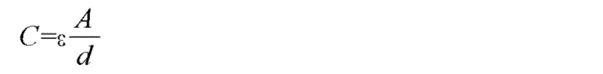
一方、図4cのように、第1電極540a上の第1絶縁体550aの傾斜部分のうち電気伝導性水溶液595と接触する境界領域Ac0に対して、次の数学式1によってキャパシタンスCが形成される。

この時のεは誘電体550aの誘電率、Aは境界領域Ac0の面積、dは第1誘電体550aの厚さを示す。
At this time, ε indicates the dielectric constant of the dielectric 550a, A indicates the area of the boundary region Ac0, and d indicates the thickness of the
ここで、ε、dは、固定値であると仮定すると、キャパシタンスCに大きい影響を及ぼすのは境界領域Ac0の面積である。 Here, assuming that ε and d are fixed values, it is the area of the boundary region Ac0 that has a large influence on the capacitance C.
即ち、境界領域Ac0の面積が大きいほど、境界領域Ac0に形成されるキャパシタンスCが大きくなる。 That is, the larger the area of the boundary region Ac0, the larger the capacitance C formed in the boundary region Ac0.
一方、液体530の曲率が可変するほど、境界領域Ac0の面積が可変するので、本発明では、センサ部962を利用して境界領域Ac0の面積を感知したり、または境界領域Ac0に形成されるキャパシタンスCを感知する。 On the other hand, the more the curvature of the liquid 530 changes, the more the area of the boundary area Ac0 changes. Sense the capacitance C.
一方、図4cのキャパシタンスは、CAc0と定義することができる。 On the other hand, the capacitance in FIG. 4c can be defined as CAc0.
図5a~図5eは、液体レンズ500の多様な曲率を例示する図面である。
5a to 5e are diagrams illustrating various curvatures of the
まず、図5aは、複数の電極(LA~LD)540a~540dと共通電極520にそれぞれ電気信号を印加することで、液体530に第1曲率Riaが形成されることを例示する。
First, FIG. 5a illustrates that the first curvature Ria is formed in the liquid 530 by applying electrical signals to the plurality of electrodes (LA to LD) 540a to 540d and the
図5aでは、液体530に第1曲率Riaが形成されることで、境界領域Aaaの面積としてAMa(>AM0)を例示する。特に、第1電極540a上の第1絶縁体550aの傾斜部分のうち電気伝導性水溶液595と接触する境界領域Aaaの面積がAMaであることを例示する。
In FIG. 5A, the first curvature Ria is formed in the liquid 530, so that AMa (>AM0) is illustrated as the area of the boundary region Aaa. In particular, the area of the boundary region Aaa that contacts the electrically conductive
数学式1によれば、図4cに比べて、図5aにおける境界領域Aaaの面積がより大きくなるので、境界領域Aaaのキャパシタンスがより大きくなる。一方、図5aのキャパシタンスは、CAaaと定義することができ、図4cのキャパシタンスであるCAc0より大きい値を有することになる。
According to
この時の第1曲率Riaは正極性の値を有すると定義することができる。例えば、第1曲率Riaが+2レベルを有すると定義することができる。 The first curvature Ria at this time can be defined as having a positive polarity value. For example, the first curvature Ria can be defined to have +2 level.
次に、図5bは、複数の電極(LA~LD)540a~540dと共通電極520にそれぞれ電気信号を印加することで、液体530に第2曲率Ribが形成されることを例示する。
Next, FIG. 5b illustrates that the second curvature Rib is formed in the liquid 530 by applying electrical signals to the plurality of electrodes (LA to LD) 540a to 540d and the
図5bでは、液体530に第2曲率Ribが形成されることで、境界領域Abaの面積としてAMb(>AMa)を例示する。特に、第1電極540a上の第1絶縁体550aの傾斜部分のうち電気伝導性水溶液595と接触する境界領域Abaの面積がAMbであることを例示する。
In FIG. 5b, AMb (> AMa ) is illustrated as the area of the boundary area Aba due to the second curvature Rib being formed in the liquid 530. In particular, it is illustrated that the area of the boundary region Aba of the inclined portion of the
数学式1によれば、図5aに比べて、図5bにおける境界領域Abaの面積がより大きくなるので、境界領域Abaのキャパシタンスがより大きくなる。一方、図5bのキャパシタンスは、CAbaと定義することができ、図5aのキャパシタンスであるCAaaより大きい値を有することになる。
According to
この時の第2曲率Rib、第1曲率Riaより大きさが大きい正極性の値を有すると定義することができる。例えば、第2曲率Ribが+4レベルを有すると定義することができる。 At this time, it can be defined that the second curvature Rib has a larger positive polarity value than the first curvature Ria. For example, the second curvature Rib can be defined to have +4 levels.
一方、図5a、図5bによれば、液体レンズ500は凸レンズとして動作し、これによって、入射光LP1が集中した出力光LP1aが出力される。
On the other hand, according to FIGS. 5a and 5b, the
次に、図5cは、複数の電極(LA~LD)540a~540dと共通電極520にそれぞれ電気信号を印加することで、液体530に第3曲率Ricが形成されることを例示する。
Next, FIG. 5c illustrates that the third curvature Ric is formed in the liquid 530 by applying electrical signals to the plurality of electrodes (LA to LD) 540a to 540d and the
特に、図5cでは、左側境界領域Acaの面積としてAMaを例示し、右側境界領域Acbの面積としてAMb(>AMa)を例示する。 In particular, in FIG. 5c, AMa is exemplified as the area of the left boundary area Aca, and AMb (> AMa ) is exemplified as the area of the right boundary area Acb.
特に、第1電極540a上の第1絶縁体550aの傾斜部分のうち電気伝導性水溶液595と接触する境界領域Acaの面積がAMaであり、第2電極540b上の第2絶縁体550bの傾斜部分のうち電気伝導性水溶液595と接触する境界領域Acbの面積がAMbであることを例示する。
In particular, the area of the boundary region Aca that contacts the electrically conductive
これによって、左側境界領域Acaのキャパシタンスは、CAaaであり、右側境界領域Acbのキャパシタンスは、CAbaである。 Accordingly, the capacitance of the left boundary area Aca is CAaa, and the capacitance of the right boundary area Acb is CAba.
この時の第3曲率Ricは正極性の値を有すると定義することができる。例えば、第3曲率Ricが+3レベルを有すると定義することができる。 The third curvature Ric at this time can be defined as having a positive polarity value. For example, the third curvature Ric can be defined to have +3 levels.
一方、図5cによれば、液体レンズ500は凸レンズとして動作し、これによって、入射光LP1が一側により集中した出力光LP1bが出力される。
On the other hand, according to FIG. 5c, the
次に、図5dは、複数の電極(LA~LD)540a~540dと共通電極520にそれぞれ電気信号を印加することで、液体530に第4曲率Ridが形成されることを例示する。
Next, FIG. 5d illustrates that the fourth curvature Rid is formed in the liquid 530 by applying electrical signals to the plurality of electrodes (LA to LD) 540a to 540d and the
図5dでは、液体530に第4曲率Ridが形成されることで、境界領域Adaの面積としてAMd(<AM0)を例示する。特に、第1電極540a上の第1絶縁体550aの傾斜部分のうち電気伝導性水溶液595と接触する境界領域Adaの面積がAMdであることを例示する。
In FIG. 5d, AMd (<AM0) is illustrated as the area of the boundary area Ada due to the formation of the fourth curvature Rid in the liquid 530. In particular, it is illustrated that the area of the boundary region Ada that contacts the electrically conductive
数学式1によれば、図4cに比べて、図5dにおける境界領域Adaの面積がより小さくなるので、境界領域Adaのキャパシタンスがより小さくなる。一方、図5dのキャパシタンスは、CAdaと定義することができ、図4cのキャパシタンスであるCAc0より小さい値を有することになる。
According to
この時の第4曲率Ridは負極性の値を有すると定義することができる。例えば、第4曲率Ridが-2レベルを有すると定義することができる。 The fourth curvature Rid at this time can be defined as having a negative polarity value. For example, the fourth curvature Rid can be defined to have a -2 level.
次に、図5eは、複数の電極(LA~LD)540a~540dと共通電極520にそれぞれ電気信号を印加することで、液体530に第5曲率Rieが形成されることを例示する。
Next, FIG. 5e illustrates that the fifth curvature Rie is formed in the liquid 530 by applying electrical signals to the plurality of electrodes (LA to LD) 540a to 540d and the
図5eでは、液体530に第5曲率Rieが形成されることで、境界領域Aeaの面積としてAMe(<AMd)を例示する。特に、第1電極540a上の第1絶縁体550aの傾斜部分のうち電気伝導性水溶液595と接触する境界領域Aeaの面積がAMeであることを例示する。
In FIG. 5e, when the fifth curvature Rie is formed in the liquid 530, AMe (<AMd) is illustrated as the area of the boundary region Aea. In particular, the area of the boundary region Aea that contacts the electrically conductive
数学式1によれば、図5dに比べて、図5eにおける境界領域Aeaの面積がより小さくなるので、境界領域Aeaのキャパシタンスがより小さくなる。一方、図5eのキャパシタンスは、CAeaと定義することができ、図5dのキャパシタンスであるCAdaより小さい値を有することになる。
According to
この時の第5曲率Rieは負極性の値を有すると定義することができる。例えば、第5曲率Rieが-4レベルを有すると定義することができる。 The fifth curvature Rie at this time can be defined as having a negative polarity value. For example, the fifth curvature Rie can be defined to have -4 level.
一方、図5d、図5eによれば、液体レンズ500は凹レンズとして動作し、これによって、入射光LP1が発散した出力光LP1cが出力される。
On the other hand, according to FIGS. 5d and 5e, the
図6は、本発明に係るカメラの内部ブロック図の一例である。 FIG. 6 is an example of an internal block diagram of the camera according to the present invention.
図面を参照すると、図6のカメラ195xは、レンズ曲率可変装置800、イメージセンサ820、イメージ処理部860、ジャイロセンサ830、液体レンズ500を含むことができる。
Referring to the drawings, the
レンズ曲率可変装置800は、レンズ駆動部860、パルス幅可変制御部840、電源供給部890を備える。
The variable
図6のレンズ曲率可変装置800の動作を説明すると、パルス幅可変制御部840が目標曲率に対応して、パルス幅可変信号Vを出力し、レンズ駆動部860がパルス幅可変信号Vと電源供給部890の電圧Vxを利用して液体レンズ500の複数の電極および共通電極に当該電圧を出力することができる。
To explain the operation of the variable
即ち、図6のレンズ曲率可変装置800は、液体レンズの曲率可変のために、オープンループシステム(Open Loop System)で動作する。
That is, the lens curvature
このような方式によれば、目標曲率に対応して、液体レンズ500の複数の電極および共通電極に当該電圧を出力する他に、実際液体レンズ500の曲率を感知できないという短所がある。
According to this method, in addition to outputting the voltage to the plurality of electrodes and the common electrode of the
また、図6のレンズ曲率可変装置800によれば、ブレ防止のために、液体レンズ500の曲率可変が必要な場合、曲率感知されないので、正確な曲率可変が困難ある短所がある。
Further, according to the lens curvature
ここで、本発明では、図6のように、レンズ曲率可変装置800をオープンループシステム(Open Loop System)で具現することなく、クローズループシステム(closed Loop System)で具現することにする。
Here, in the present invention, as shown in FIG. 6, the lens curvature
即ち、液体レンズ500の曲率を把握するために、液体レンズ500内の液体内部の電極上の絶縁体と、電気伝導性水溶液595と接触する境界領域Ac0に形成されるキャパシタンスを感知し、感知されるキャパシタンスをフィードバックして、目標曲率と現在曲率の差を演算し、その差に対応して制御を行う。
That is, in order to grasp the curvature of the
これによれば、迅速かつ正確に液体レンズ500の曲率を把握することができ、また、目標曲率に対応するように、液体レンズ500の曲率を迅速かつ正確に制御できるようになる。これについては、図7以下を参照してより詳しく記述する。
According to this, the curvature of the
図7は、本発明の実施例に係るカメラの内部ブロック図の一例である。 FIG. 7 is an example of an internal block diagram of a camera according to an embodiment of the present invention.
図面を参照すると、本発明の実施例に係るカメラ195mは、液体レンズ500の曲率を可変するレンズ曲率可変装置900と、液体レンズ500からの光を電気信号に変換するイメージセンサ820と、イメージセンサ820からの電気信号に基づいてイメージ処理をするイメージ処理部930を含むことができる。
Referring to the drawings, a
特に、図7のカメラ195mは、ジャイロセンサ915をさらに含むことができる。
In particular, the
イメージ処理部930は、イメージに対する焦点情報AFを出力することができ、ジャイロセンサ915は、ブレ情報OISを出力することができる。
The
これによって、レンズ曲率可変装置900内の制御部970は、焦点情報AFとブレ情報OISに基づいて、目標曲率を決定することができる。
Thereby, the
一方、本発明の実施例に係るレンズ曲率可変装置900は、液体レンズ500に電気信号を印加するレンズ駆動部960と、電気信号に基づいて形成された液体レンズ500の曲率を感知するためのセンサ部962と、感知された曲率に基づいて、液体レンズ500の目標曲率を形成するようにレンズ駆動部960を制御する制御部970を含み、センサ部962は、液体レンズ500内の電極上の絶縁体と電気伝導性水溶液595の間の境界領域Ac0の面積の大きさまたは面積の変化を感知することができる。これによって、迅速かつ正確にレンズの曲率を感知できるようになる。
On the other hand, the lens curvature
一方、本発明の実施例に係るレンズ曲率可変装置900は、印加される電気信号に基づいて曲率が可変する液体レンズ500をさらに備えることができる。
Meanwhile, the lens curvature
一方、本発明の実施例に係るレンズ曲率可変装置900は、電源を供給する電源供給部990と、センサ部962で感知されたキャパシタンスと関連した信号をデジタル信号に変換するADコンバータ967をさらに備えることができる。
Meanwhile, the lens curvature
一方、レンズ曲率可変装置900は、レンズ駆動部960で、液体レンズ500内の各電極(共通電極、複数の電極)に電気信号を供給するための複数の導電性ラインCA1、CA2と、複数の導電性ラインのうちいずれか1つ(CA2)とセンサ部962の間に配置されるスイッチング素子SWLをさらに含むことができる。
On the other hand, the lens curvature
図面では、液体レンズ500内の複数の電極のうちいずれか1つに電気信号を印加するための導電性ラインCA2とセンサ部962の間に、スイッチング素子SWLが配置されることを例示する。この時、導電性ラインCA2と、スイッチング素子SWLの一端または液体レンズ500との接点をnode Aと命名することができる。
The drawings illustrate that a switching element SWL is disposed between a conductive line CA2 for applying an electric signal to any one of the plurality of electrodes in the
一方、本発明では、液体レンズ500の曲率感知のために、複数の導電性ラインCA1、CA2を通じて、液体レンズ500内の各電極(共通電極、複数の電極)に電気信号を印加する。これによって、図5a~図5eなどのように、液体530に曲率が形成される。
Meanwhile, in the present invention, in order to sense the curvature of the
例えば、第1期間の間、スイッチング素子SWLがターンオンされる。 For example, the switching element SWL is turned on during the first period.
この時、スイッチング素子SWLがターンオンされてセンサ部962と導通された状態で、液体レンズ500内の電極に電気信号が印加される場合、液体レンズ500内に曲率が形成され、曲率形成に対応する電気信号が、スイッチング素子SWLを経てセンサ部962に供給される。
At this time, when an electric signal is applied to the electrode in the
これによって、センサ部962は、スイッチング素子SWLのオン期間の間、液体レンズ500からの電気信号に基づいて、液体レンズ500の液体レンズ500内の電極上の絶縁体と電気伝導性水溶液595の間の境界領域Ac0の面積の大きさまたは面積の変化を感知したり、境界領域Ac0のキャパシタンスを感知することができる。
Accordingly, during the ON period of the switching element SWL, the
次に、第2期間の間、スイッチング素子SWLがターンオフされ、液体レンズ500内の電極に電気信号が継続して印加される。これによって、液体530に曲率が形成される。
Next, during the second period, the switching element SWL is turned off, and an electric signal is continuously applied to the electrode within the
次に、第3期間の間、スイッチング素子SWLがターンオフされ、液体レンズ500内の電極に電気信号が印加されないか、ローレベルの電気信号が印加される。
Next, during the third period, the switching element SWL is turned off, and no electrical signal or a low-level electrical signal is applied to the electrodes within the
次に、第4期間の間、スイッチング素子SWLがターンオンされる。 Next, switching element SWL is turned on during the fourth period.
この時、スイッチング素子SWLがターンオンされてセンサ部962と導通された状態で、液体レンズ500内の電極に電気信号が印加される場合、液体レンズ500内に曲率が形成され、曲率形成に対応する電気信号が、スイッチング素子SWLを経てセンサ部962に供給される。
At this time, when an electric signal is applied to the electrode in the
一方、第1期間の間感知されたキャパシタンスに基づいて演算された曲率が目標曲率より小さい場合、制御部970は、目標曲率に到達するようにするために、駆動部960に供給されるパルス幅可変制御信号のパルス幅が増加するように制御することができる。
On the other hand, if the curvature calculated based on the capacitance sensed during the first period is smaller than the target curvature, the
これによって、共通電極530と複数の電極にそれぞれ印加されるパルスの時差が大きくなり、これによって、液体530に形成された曲率が大きくなる。
This increases the time difference between the pulses applied to the
第4期間の間、スイッチング素子SWLがターンオンされてセンサ部962と導通された状態で、液体レンズ500内の電極に電気信号が印加される場合、液体レンズ500内に曲率が形成され、曲率形成に対応する電気信号が、スイッチング素子SWLを経てセンサ部962に供給される。
During the fourth period, when an electric signal is applied to the electrode in the
これによって、センサ部962は、スイッチング素子SWLのオン期間の間、液体レンズ500からの電気信号に基づいて、液体レンズ500の液体レンズ500内の電極上の絶縁体と電気伝導性水溶液595の間の境界領域Ac0の面積の大きさまたは面積の変化を感知したり、境界領域Ac0のキャパシタンスを感知することができる。
Accordingly, during the ON period of the switching element SWL, the
これによって、制御部970は、感知されるキャパシタンスに基づいて、曲率を演算することができ、目標曲率に到達したのか否かを判断することができる。一方、目標曲率に到達した場合、制御部970は、該当する電気信号を各電極に供給するように制御することができる。
Accordingly, the
これによれば、電気信号供給により、液体530の曲率を形成し、直ちに液体の曲率を感知できるようになる。よって、迅速かつ正確に液体レンズ500の曲率を把握できるようになる。
According to this, the curvature of the liquid 530 is formed by supplying an electric signal, and the curvature of the liquid can be immediately sensed. Therefore, the curvature of the
一方、図面におけるレンズ駆動部960とセンサ部962は、1つのモジュール965で形成されてもよい。
Meanwhile, the
一方、図面におけるレンズ駆動部960とセンサ部962、制御部970、電源供給部990、ADコンバータ967、スイッチング素子SWLは、システムオンチップ(system on chip、SOC)として、1つのチップ(chip)で具現することができる。
On the other hand, the
一方、液体レンズ500は、図4a~図4cで説明したように、共通電極(COM)520と、共通電極(COM)520上の液体530と、液体530上の電気伝導性水溶液595と、液体530と離隔して配置される複数の電極(LA~LD)540a~540dを含むことができる。
On the other hand, the
一方、センサ部962は、図5a~図5eで説明したように、液体レンズ500内の電極上の絶縁体と電気伝導性水溶液595の間の境界領域Ac0の、面積、または面積の変化、またはこれに対応するキャパシタンスを感知することができる。
On the other hand, as explained in FIGS. 5a to 5e, the
一方、センサ部962で感知されたキャパシタンスと関連したアナログ信号は、ADコンバータ967を通じてデジタル信号に変換され、制御部970に入力される。
Meanwhile, an analog signal related to the capacitance sensed by the
一方、図5a~図5eで説明したように、液体レンズ500の曲率が大きくなるほど境界領域Ac0の面積が大きくなり、結局境界領域Ac0のキャパシタンスが大きくなる。
On the other hand, as described with reference to FIGS. 5a to 5e, the larger the curvature of the
本発明では、このような特性を利用して、センサ部962で感知されたキャパシタンスを利用して曲率を演算する。
In the present invention, the curvature is calculated using the capacitance sensed by the
一方、制御部970は、液体レンズ500の曲率が大きくなるようにするために、液体レンズ500に印加される電圧のレベルまたはパルス幅が増加するように制御することができる。
Meanwhile, the
一方、図5cのように、複数の電極(LA~LD)540a~540dのうち第1電極540aと第3電極540cに異なるレベルの電圧または異なるパルス幅の電圧が印加される場合、液体530の第1端部Acaの第1キャパシタンスと、液体530の第2端部Acbの第2キャパシタンスが異なることになる。
On the other hand, as shown in FIG. 5c, when voltages of different levels or pulse widths are applied to the
これによって、センサ部962は、液体530の第1端部Acaと、第2端部Acbのそれぞれのキャパシタンスを感知することができる。
Accordingly, the
このように、一方、液体レンズ500内の液体530の端部周辺のキャパシタンスを感知することで、レンズの曲率を正確に検出できるようになる。
In this manner, on the other hand, by sensing the capacitance around the edge of the liquid 530 within the
即ち、一方、液体レンズ500内の電極上の絶縁体と電気伝導性水溶液595の間の複数の境界領域のキャパシタンスを感知することで、液体レンズの曲率を正確に検出できるようになる。
That is, on the other hand, by sensing the capacitance of a plurality of boundary regions between the insulator on the electrode in the
一方、共通電極(COM)520に一定電圧が印加され、複数の電極(LA~LD)540a~540dにパルスが印加される場合、センサ部962は、複数の電極(LA~LD)540a~540d上の絶縁体と電気伝導性水溶液595の間の複数の境界領域に対するキャパシタンスを感知することができる。
On the other hand, when a constant voltage is applied to the common electrode (COM) 520 and a pulse is applied to the plurality of electrodes (LA to LD) 540a to 540d, the
一方、複数の電極(LA~LD)540a~540dに一定電圧が印加され、共通電極(COM)520にパルスが印加される場合、センサ部962は、共通電極(COM)520上の絶縁体と電気伝導性水溶液595の間の境界領域に対するキャパシタンスを感知することができる。
On the other hand, when a constant voltage is applied to the plurality of electrodes (LA to LD) 540a to 540d and a pulse is applied to the common electrode (COM) 520, the
一方、制御部970は、センサ部962で感知されたキャパシタンスに基づいて、液体レンズ500の曲率を演算することができる。
Meanwhile, the
この時、制御部970は、センサ部962で感知されたキャパシタンスが大きくなるほど、液体レンズ500の曲率が大きくなると演算することができる。
At this time, the
そして、制御部970は、液体レンズ500が目標曲率を有するように制御することができる。
The
一方、制御部970は、センサ部962で感知されたキャパシタンスに基づいて液体レンズ500の曲率を演算し、演算された曲率と目標曲率に基づいて、パルス幅可変信号Vをレンズ駆動部960に出力することができる。
On the other hand, the
これによって、レンズ駆動部960は、パルス幅可変信号Vと電源供給部990の電圧LV1、LV2を利用して複数の電極(LA~LD)540a~540dの複数の電極および共通電極520に当該電気信号を出力することができる。
Accordingly, the
このように、液体レンズ500のキャパシタンスを感知し、これをフィードバックして、レンズの曲率が可変するように液体レンズ500に電気信号を印加することで、迅速かつ正確にレンズの曲率を可変できるようになる。
In this way, by sensing the capacitance of the
一方、制御部970は、演算された曲率と目標曲率に基づいて、曲率エラーを演算するイコライザー972と、演算された曲率エラーΦに基づいて、パルス幅可変信号Vを生成して出力するパルス幅可変制御部940を含むことができる。
On the other hand, the
これによって、制御部970は、演算された曲率が目標曲率より大きくなる場合、演算された曲率エラーΦに基づいて、パルス幅可変信号Vのデューティーが増加するように制御したり、または液体レンズ500に印加される複数のパルスの時差であるディレイが増加するように制御することができる。これによって、迅速かつ正確に液体レンズ500の曲率を可変できるようになる。
Accordingly, when the calculated curvature becomes larger than the target curvature, the
一方、制御部970は、イメージ処理部930からの焦点情報AFと、ジャイロセンサ915からのブレ情報OISを受信し、焦点情報AFとブレ情報OISに基づいて、目標曲率を決定することができる。
On the other hand, the
この時、決定された目標曲率のアップデート周期は、感知された液体レンズ500のキャパシタンスに基づいて、演算された曲率のアップデート周期より長いことが好ましい。
At this time, it is preferable that the update period of the determined target curvature is longer than the update period of the calculated curvature based on the sensed capacitance of the
結局、演算された曲率のアップデート周期が、目標曲率のアップデート周期より小さいので、速かに液体レンズ500の曲率を可変して、所望の曲率に変更できるようになる。
After all, since the update period of the calculated curvature is smaller than the update period of the target curvature, the curvature of the
図8a~図12bは、図7の説明に参照される図面である。 8a to 12b are drawings referred to in the description of FIG. 7.
まず、図8aは、図6のレンズ曲率可変装置800と図7のレンズ曲率可変装置900における液体レンズ500の曲率変化曲線を示す図面である。
First, FIG. 8a is a diagram showing curvature change curves of the
図面を参照すると、GRoは、図6のレンズ曲率可変装置800における液体レンズ500の曲率変化曲線を示し、GRcは、図8aのレンズ曲率可変装置900における液体レンズ500の曲率変化曲線を示す。
Referring to the drawings, GRo indicates a curvature change curve of the
特に、Tx時点に目標曲率への変化のための電圧がそれぞれ液体レンズ500に印加され、Ty時点に電圧印加が中止されることを例示する。
In particular, a voltage for changing the target curvature is applied to the
両曲線を比較すると、オープンループシステムの図6のレンズ曲率可変装置800の場合、目標ディオプトリ(target diopter)に遅くセトリング(settling)され、正確ではないが、クローズループシステムの図7のレンズ曲率可変装置900の場合、迅速かつ正確にセトリングされることが分かる。
Comparing both curves, it can be seen that the variable
オープンループシステムの図6のレンズ曲率可変装置800に比べて、クローズループシステムの図7のレンズ曲率可変装置900の場合、セトリングタイミングが略70%程度はやくなる。
Compared to the variable
結局、クローズループシステムの図7のレンズ曲率可変装置900を用いると、迅速かつ正確に曲率およびディオプトリ(diopter)を形成することができる。
In conclusion, using the variable
一方、ディオプトリは、図5a~図5eで記述した液体530の曲率に対応するものであってもよい。これによって、液体530の曲率が大きくなるほどディオプトリが大きくなり、曲率が小さいほどディオプトリが小さいと定義することができる。 On the other hand, the diopter may correspond to the curvature of the liquid 530 described in FIGS. 5a-5e. Accordingly, it can be defined that the larger the curvature of the liquid 530, the larger the diopter, and the smaller the curvature, the smaller the diopter.
例えば、図5a~図5bのように、曲率が+2、+4レベルを有する場合、ディオプトリも、凸レンズに対応する+2、+4レベルを有すると定義することができ、図4cのように、曲率が0レベルである場合、ディオプトリが、平面レンズに対応する0レベルを有すると定義することができ、図5d~図5eのように、曲率が-2、-4レベルを有する場合、ディオプトリも凹レンズに対応する-2、-4レベルを有すると定義することができる。 For example, if the curvature has +2 and +4 levels as shown in Figures 5a and 5b, the diopter can also be defined as having +2 and +4 levels corresponding to a convex lens, and as in Figure 4c, the curvature is 0. If the curvature is a level, then the diopter can be defined as having a 0 level, which corresponds to a flat lens, and if the curvature has -2 and -4 levels, as shown in Figures 5d to 5e, the diopter also corresponds to a concave lens. It can be defined as having -2 and -4 levels.
図8bは、図7のレンズ曲率可変装置900のうち共通電極(COM)、第1電極(LA)、スイッチング素子SWLに対するタイミング図を例示する。
FIG. 8b illustrates a timing diagram for the common electrode (COM), the first electrode (LA), and the switching element SWL in the lens curvature
図面を参照すると、T1とT3時点の間の期間DT1の間、スイッチング素子SWLがオンされる。 Referring to the drawing, the switching element SWL is turned on during a period DT1 between times T1 and T3.
一方、センサ部962を通じて、境界領域Ac0のキャパシタンスを感知するために、T1とT3時点の間の期間DT1中に、液体レンズ500に曲率が形成されるようにすることが好ましい。
Meanwhile, in order to sense the capacitance of the boundary area Ac0 through the
一方、センサ部962におけるセンシングの正確性、安定性のために、本発明では、T1とT3時点の間の期間DT1の間、液体レンズ500内の共通電極と、複数の電極のうちいずれか1つにパルスが印加されるものとする。
On the other hand, for the accuracy and stability of sensing in the
特に、図8bのように、共通電極530に、T2時点にDT2のパルス幅を有するパルスが印加される。これによって、T2時点以後に液体レンズ500に曲率が形成される。
In particular, as shown in FIG. 8b, a pulse having a pulse width of DT2 is applied to the
これによって、センサ部962は、T1とT3時点の間の期間DT1の間、T2時点からT3時点の間の期間の間、液体レンズ500内の電極上の絶縁体と電気伝導性水溶液595の間の境界領域Ac0の面積の大きさまたは面積の変化に対応して、電気伝導性水溶液595と電極が形成するキャパシタンスを感知することができる。
Accordingly, the
一方、センサ部962は、T2時点からT3時点の間の期間の間、液体レンズ500内の電極上の絶縁体と電気伝導性水溶液595の間の境界領域Ac0の面積の大きさまたは面積の変化に対応する電気伝導性水溶液595と電極の間の電位差または電流を感知することもできる。
On the other hand, the
次に、T4時点に第1電極(LA)にDT3のパルス幅を有するパルスが印加される。 Next, at time T4, a pulse having a pulse width of DT3 is applied to the first electrode (LA).
即ち、T2時点に共通電極(COM)にハイレベルの電圧が印加され、T4時点に第1電極(LA)にハイレベルの電圧が印加される。 That is, a high level voltage is applied to the common electrode (COM) at time T2, and a high level voltage is applied to the first electrode (LA) at time T4.
共通電極(COM)に印加されるパルスと、第1電極(LA)に印加されるパルスの時差DFF1によって、液体レンズ500内の液体530に形成される曲率が可変する。
The curvature formed in the liquid 530 within the
例えば、パルスの時差DFF1が大きくなるほど、電極、電気伝導性水溶液595と接触する境界領域Ac0の面積の大きさが増加し、これによって、キャパシタンスが大きくなり、結局曲率が大きくなる。
For example, as the pulse time difference DFF1 increases, the area of the boundary region Ac0 in contact with the electrode and the electrically conductive
図9aと図9bは、センサ部の多様な方式を示す図面である。 9a and 9b are diagrams illustrating various types of sensor units.
まず、図9aは、別途の追加パルス信号の印加なしに、キャパシタンスを感知できるセンサ部962aを示す。
First, FIG. 9a shows a
図9aのレンズ曲率可変装置900a内のセンサ部962aは、Continuous Sensing方式で動作することができる。
The
このために、図9aのセンサ部962aは、複数の電極(LA~LD)540a~540dの少なくとも1つの電極からの電気信号をフィルタリングするフィルター1112と、フィルター1112からの電気信号のピークを検出するピーク検出器(peak detector)1114と、ピーク検出器1114からの電気信号を増幅する増幅器(Programmable gain amplifier:PGA)1116を含むことができる。
To this end, the
具体的に、図9aのセンサ部962aは、複数の電極(LA~LD)540a~540dの少なくとも1つの電極に接続されたスイッチング素子SWLのターンオン区間の間、液体レンズ500のキャパシタンスを感知することができる。
Specifically, the
次に、図9bは、共通電極(COM)520に別途の追加パルス信号を印加して、追加パルス信号印加中に、キャパシタンスを感知できるセンサ部962bを示す。
Next, FIG. 9b shows a
図9bのレンズ曲率可変装置900b内のセンサ部962bは、Discrete Sensing方式で動作することができる。
The
このために、図9bのセンサ部962bは、複数の電極(LA~LD)540a~540dの少なくとも1つの電極からのキャパシタンスを電圧に変換する変換部1122と、電圧を増幅する増幅器1124を含むことができる。
To this end, the
具体的に、複数の電極(LA~LD)540a~540dの少なくとも1つの電極に接続されたスイッチング素子SWLのターンオン区間の間、共通電極(COM)520に追加パルス信号が印加され、図9bのセンサ部962bは、スイッチング素子SWLのターンオン区間の間、追加パルス信号に基づいて形成された液体レンズ500のキャパシタンスを感知することができる。
Specifically, during the turn-on period of the switching element SWL connected to at least one electrode of the plurality of electrodes (LA to LD) 540a to 540d, an additional pulse signal is applied to the common electrode (COM) 520, as shown in FIG. 9b. The
一方、図9aおよび図9bの全てに適用可能なレンズ駆動部は、図10のように例示できる。 On the other hand, a lens driving section applicable to both of FIGS. 9a and 9b can be illustrated as shown in FIG. 10.
図10は、図9aまたは図9bのレンズ駆動部の内部回路図の一例である。 FIG. 10 is an example of an internal circuit diagram of the lens driving section of FIG. 9a or 9b.
図面を参照すると、図10のレンズ駆動部960aは、レンズを駆動する第1駆動部961と、センサを駆動する第2駆動部1310を含むことができる。
Referring to the drawings, the
一方、レンズ駆動部960aは、第2駆動部1310にパルス幅可変信号を出力するパルス幅制御部1320をさらに備えることができる。
Meanwhile, the
一方、パルス幅制御部1320は、図7のパルス幅制御部940内に備えられてもよい。
Meanwhile, the
第1駆動部961は、相互直列接続される第1上アーム、下アームスイッチング素子(upper-arm and lower-arm switching elements)Sa、S’aと、相互直列接続される第2上アーム、下アームスイッチング素子Sb、S’bを含むことができる。
The
この時、第1上アーム、下アームスイッチング素子Sa、S’aと、第2上アーム、下アームスイッチング素子Sb、S’bは相互並列接続される。 At this time, the first upper arm and lower arm switching elements Sa and S'a and the second upper and lower arm switching elements Sb and S'b are connected in parallel with each other.
第1上アームスイッチング素子Saと、第2上アームスイッチング素子Sbには、電源供給部990からのLV2レベルの電源が供給される。
LV2 level power is supplied from the
第2駆動部1310は、相互直列接続される第3上アーム、下アームスイッチング素子Sc、S’cを含むことができる。
The
第3上アームスイッチング素子Scには、レベルが低い追加パルスを生成するために、電源供給部990からのLV2レベルより低いLV1レベルの電源が供給される。
The third upper arm switching element Sc is supplied with power at an LV1 level lower than the LV2 level from the
第1上アームスイッチング素子Saと第1下アームスイッチング素子S’aの間のノードまたは第3上アームスイッチング素子Scと第3下アームスイッチング素子S’cの間のノードを通じて共通電極520に電圧が印加され、第2上アームスイッチング素子Sbと第2下アームスイッチング素子S’bの間のノードを通じて第1電極(LA)540aに電圧が印加される。
A voltage is applied to the
図11aは、図10のレンズ駆動部960aの動作を説明するための波形図の一例であり、図11bは、図9aのセンサ部962aの動作を説明するために参照される図面である。
FIG. 11a is an example of a waveform diagram for explaining the operation of the
図面を参照すると、T1とT3時点の間の期間DT1の間、スイッチング素子SWLにハイレベルが印加され、スイッチング素子SWLがオンされる。 Referring to the drawing, during a period DT1 between times T1 and T3, a high level is applied to the switching element SWL, and the switching element SWL is turned on.
一方、T1とT3時点の間の期間DT1の間、Sbスイッチング素子とS’bスイッチング素子にそれぞれローレベルの制御信号LAP、LAMが印加され、Sbスイッチング素子とS’bスイッチング素子がフローティングされる。 On the other hand, during the period DT1 between time points T1 and T3, low-level control signals LAP and LAM are applied to the Sb switching element and the S'b switching element, respectively, and the Sb switching element and the S'b switching element are floated. .
Sbスイッチング素子とS’bスイッチング素子は、相補的にターンオンされるが、スイッチング素子SWLがオンされる期間の間、全てフローティングされる。 The Sb switching element and the S'b switching element are turned on in a complementary manner, but are all floated during the period in which the switching element SWL is turned on.
一方、T2時点に、Saスイッチング素子に印加される制御信号CMHPはハイレベル、S’aスイッチング素子に印加される制御信号CMHMはローレベルに変わる。 Meanwhile, at time T2, the control signal CMHP applied to the Sa switching element changes to high level, and the control signal CMHM applied to the S'a switching element changes to low level.
一方、Saスイッチング素子とS’aスイッチング素子は、常に相補的にターンオンされる。 Meanwhile, the Sa switching element and the S'a switching element are always turned on in a complementary manner.
一方、T2時点に、Saスイッチング素子に印加される制御信号CMHPはハイレベルに変わり、T4時点に、Sbスイッチング素子に印加される制御信号LApがハイレベルに変わる。 On the other hand, at time T2, the control signal CMHP applied to the Sa switching element changes to high level, and at time T4, the control signal LAp applied to the Sb switching element changes to high level.
T1とT3時点の間の期間DT1のうちT2時点にDT2のパルス幅を有するパルスが印加される。これによって、T2時点以後に液体レンズ500に曲率が形成される。
A pulse having a pulse width of DT2 is applied at time T2 of the period DT1 between time T1 and time T3. As a result, a curvature is formed in the
これによって、センサ部962は、T1とT3時点の間の期間DT1の間、T2時点からT3時点の間の期間の間、液体レンズ500内の電極上の絶縁体と電気伝導性水溶液595の間の境界領域Ac0の面積の大きさまたは面積の変化に対応するキャパシタンスを感知することができる。
Accordingly, the
具体的に、T2時点からT3時点の間の期間の間、フィルター1112にLV3レベルの信号が印加され、ピーク検出器114がこれを検出し、PGA1116が増幅される。これによって、T2時点からT3時点の間の期間の間、液体レンズ500内の電極上の絶縁体と電気伝導性水溶液595の間の境界領域Ac0の面積の大きさまたは面積の変化に対応するキャパシタンスを感知することができる。
Specifically, during the period between time T2 and time T3, an LV3 level signal is applied to filter 1112, peak detector 114 detects this, and
一方、即ち、T2時点に共通電極(COM)にハイレベルの電圧が印加され、T4時点に第1電極(LA)にハイレベルの電圧が印加される。 On the other hand, a high level voltage is applied to the common electrode (COM) at time T2, and a high level voltage is applied to the first electrode (LA) at time T4.
共通電極(COM)に印加されるパルスと、第1電極(LA)に印加されるパルスの時差DFF1によって、液体レンズ500内の液体530に形成される曲率が可変する。
The curvature formed in the liquid 530 within the
例えば、パルスの時差DFF1が大きくなるほど、電極、電気伝導性水溶液595と接触する境界領域Ac0の面積の大きさが増加し、これによって、キャパシタンスが大きくなり、結局曲率が大きくなる。
For example, as the pulse time difference DFF1 increases, the area of the boundary region Ac0 in contact with the electrode and the electrically conductive
一方、図11aの場合、図10の第2駆動部1310は動作しない。
On the other hand, in the case of FIG. 11a, the
次に、T5時点に、共通電極520が接地され、T6時点に、第1電極(LA)540aが接地される。以後、T7およびT8時点は、T1およびT2時点などを繰り返す。
Next, at time T5, the
図11cは、図10のレンズ駆動部960aの動作を説明するための波形図の別の例であり、図11dは、図9aのセンサ部962aの動作を説明するために参照される図面である。
FIG. 11c is another example of a waveform diagram for explaining the operation of the
図11cは、図11aの波形図と類似しているが、図10の第2駆動部1310内のスイッチング素子Sc、S’cの動作のための制御信号CMLP、CMLMが図示されることにその差がある。
FIG. 11c is similar to the waveform diagram of FIG. 11a, except that the control signals CMLP and CMLM for the operation of the switching elements Sc and S'c in the
センサ部SWLは、T1とT2の期間の間ターンオンされ、T2以後からターンオフされる。 The sensor unit SWL is turned on between T1 and T2, and is turned off after T2.
一方、T2時点に、Saスイッチング素子に印加される制御信号CMHPはハイレベルに変わり、T3時点に、Sbスイッチング素子に印加される制御信号LApがハイレベルに変わる。 On the other hand, at time T2, the control signal CMHP applied to the Sa switching element changes to high level, and at time T3, the control signal LAp applied to the Sb switching element changes to high level.
T1とT2の期間中に、Scスイッチング素子がターンオンされる。これによって、図11dのように、電源供給部990bから供給されるLV1レベルを有する追加パルスSMPが、共通電極(COM)に印加される。
During the period T1 and T2, the Sc switching element is turned on. Accordingly, as shown in FIG. 11d, the additional pulse SMP having the LV1 level supplied from the
これによって、センサ部962は、T1とT2時点の間の期間DT1の間、液体レンズ500内の電極上の絶縁体と電気伝導性水溶液595の間の境界領域Ac0の面積の大きさまたは面積の変化に対応するキャパシタンスを感知することができる。
Accordingly, during the period DT1 between time points T1 and T2, the
具体的に、T1時点からT2時点の間の期間の間、フィルター1112にLV3レベルより低いLV5レベルの信号が印加され、ピーク検出器114がこれを検出し、PGA1116が増幅される。これによって、T1時点からT2時点の間の期間の間、液体レンズ500内の電極上の絶縁体と電気伝導性水溶液595の間の境界領域Ac0の面積の大きさまたは面積の変化に対応するキャパシタンスを感知することができる。
Specifically, during the period between time T1 and time T2, a signal of LV5 level lower than LV3 level is applied to filter 1112, peak detector 114 detects this, and
次に、T3時点に共通電極CQMに、DT2のパルス幅を有し、LV1レベルより大きいLV2レベルを有するパルスSLPが印加される。 Next, at time T3, a pulse SLP having a pulse width of DT2 and having an LV2 level higher than the LV1 level is applied to the common electrode CQM.
次に、T4時点に第1電極(LA)にDT3のパルス幅を有するパルスが印加される。 Next, at time T4, a pulse having a pulse width of DT3 is applied to the first electrode (LA).
共通電極CQMに印加されるパルスと、第1電極(LA)に印加されるパルスの時差DFF1によって、液体レンズ500内の液体530に形成される曲率が可変する。
The curvature formed in the liquid 530 within the
例えば、パルスの時差DFF1が小さいほど、電極、電気伝導性水溶液595と接触する境界領域Ac0の面積の大きさが増加し、これによって、キャパシタンスが大きくなり、結局曲率が小さくなることができる。
For example, the smaller the pulse time difference DFF1, the larger the area of the boundary region Ac0 in contact with the electrode and the electrically conductive
図11eは、図10のレンズ駆動部960aの動作を説明するための波形図のまた別の例であり、図11fは、図9bのセンサ部962bの動作を説明するために参照される図面である。
FIG. 11e is another example of a waveform diagram for explaining the operation of the
図11eは、図11cの波形図と類似しているが、図11cとは異なって、T1~T2の期間の間、図10の第2駆動部1310内のスイッチング素子Sc、S’cの動作のための制御信号CMLP、CMLMが、1つのパルスではなく、複数のパルスを有することにその差がある。
FIG. 11e is similar to the waveform diagram of FIG. 11c, but differs from FIG. 11c in that the switching elements Sc and S'c in the
これによって、図11fのように、T1~T2の期間の間、共通電極(COM)に、複数のパルスSMPaが印加される。 As a result, a plurality of pulses SMPa are applied to the common electrode (COM) during the period T1 to T2, as shown in FIG. 11f.
これによって、センサ部962は、T1とT2時点の間の期間DT1の間、液体レンズ500内の電極上の絶縁体と電気伝導性水溶液595の間の境界領域Ac0の面積の大きさまたは面積の変化に対応するキャパシタンスを感知することができる。
Accordingly, during the period DT1 between time points T1 and T2, the
具体的に、T1時点からT2時点の間の期間の間、C2Vコンバータ1122にLV3複数のパルス信号が印加され、SC増幅器1124が複数のパルス信号を増幅することができる。これによって、T1時点からT2時点の間の期間の間、液体レンズ500内の電極上の絶縁体と電気伝導性水溶液595の間の境界領域Ac0の面積の大きさまたは面積の変化に対応するキャパシタンスを感知することができる。特に、センサ部962の出力により、キャパシタンスに対応する電圧信号が出力される。
Specifically, during the period between time T1 and time T2, LV3 pulse signals may be applied to the
図13aは、本発明の別の実施例に係るカメラの内部ブロック図の一例である。 FIG. 13a is an example of an internal block diagram of a camera according to another embodiment of the present invention.
図面を参照して説明すると、図13aのカメラ195nおよびレンズ曲率可変装置900bは、図7のカメラ195mおよびレンズ曲率可変装置900と類似しているが、センサ部962が、複数の電極(LA~LD)540a~540dに対応する複数の液体530の端部のキャパシタンスを感知することにその差がある。
Referring to the drawings, the
このために、共通電極(COM)520にローレベルの電圧が印加され、複数の電極(LA~LD)540a~540dにパルス信号が印加される。 For this purpose, a low level voltage is applied to the common electrode (COM) 520, and pulse signals are applied to the plurality of electrodes (LA to LD) 540a to 540d.
一方、センサ部9620の動作のために、複数の電極(LA~LD)540a~540dと液体レンズ500の間に接続される導電性ラインCA~CDとセンサ部962の間に複数のスイッチング素子SWLa~SWLdが備えられることが好ましい。
On the other hand, for the operation of the sensor section 9620, a plurality of switching elements SWLa are connected between the conductive lines CA to CD connected between the plurality of electrodes (LA to LD) 540a to 540d and the
センサ部962は、複数のスイッチング素子SWLa~SWLdがターンオンされる区間の間、複数の電極(LA~LD)540a~540dに印加されるパルス信号に基づいて、複数の電極(LA~LD)540a~540d上の絶縁体と電気伝導性水溶液の間の境界領域に対するキャパシタンスを感知し、これを制御部970に伝達することができる。
The
これによって、液体レンズ500の複数の境界領域に対するキャパシタンスを感知できるようになる。
This makes it possible to sense the capacitance for multiple boundary areas of the
さらに、図13aのカメラ195nで、手ブレ補正に対応して、複数の電極(LA~LD)540a~540dに印加される電圧を可変して、非対称曲率形成などが可能であるので、手ブレ補正を正確かつ迅速に行うことができるようになる。
Furthermore, in the
図13bは、本発明のさらに別の実施例に係るカメラの内部ブロック図の一例である。 FIG. 13b is an example of an internal block diagram of a camera according to yet another embodiment of the present invention.
図面を参照して説明すると、図13bのカメラ195oおよびレンズ曲率可変装置900cは、図7のカメラ195mおよびレンズ曲率可変装置900と類似しているが、センサ部962が、複数の電極(LA~LD)540a~540dに対応する液体の端部のキャパシタンスを感知することにその差がある。
Referring to the drawings, the camera 195o and variable
このために、複数の電極(LA~LD)540a~540dにローレベルの電圧が印加され、共通電極(COM)520にパルス信号が印加される。 For this purpose, a low level voltage is applied to the plurality of electrodes (LA to LD) 540a to 540d, and a pulse signal is applied to the common electrode (COM) 520.
一方、センサ部9620の動作のために、複数の電極(LA~LD)540a~540dと液体レンズ500の間に接続される導電性ラインCA~CDではなく、共通電極(COM)と液体レンズ500の間に接続される導電性ラインCMとセンサ部962の間に、スイッチング素子SWLが備えられることが好ましい。
On the other hand, for the operation of the sensor unit 9620, instead of the conductive lines CA to CD connected between the plurality of electrodes (LA to LD) 540a to 540d and the
センサ部962は、スイッチング素子SWLがターンオンされる区間の間、共通電極(COM)に印加されるパルス信号に基づいて、電極上の絶縁体と電気伝導性水溶液の間の境界領域に対するキャパシタンスを感知し、これを制御部970に伝達することができる。
The
これによって、液体レンズ500の境界領域に対するキャパシタンスを感知できるようになる。
This allows sensing the capacitance to the boundary area of the
さらに、図13bのカメラ195oで、手ブレ補正に対応して非対称曲率形成などが可能であるので、手ブレ補正を正確かつ迅速に行うことができるようになる。 Furthermore, since the camera 195o in FIG. 13b is capable of forming an asymmetrical curvature in response to camera shake correction, camera shake correction can be performed accurately and quickly.
一方、図7~図13bで説明したレンズ曲率可変装置900は、移動端末、車両、TV、ドローン、ロボット、ロボット掃除機など多様な電子機器に採用可能である。
Meanwhile, the lens curvature
一方、本発明のレンズ曲率可変装置の動作方法は、レンズ曲率可変装置に備えられたプロセッサが読み取ることのできる記録媒体に、プロセッサが読み取ることのできるコードとして具現することが可能である。プロセッサが読み取ることのできる記録媒体は、プロセッサによって読み取ることのできるデータが格納されるあらゆる種類の記録装置を含む。プロセッサが読み取ることのできる記録媒体の例としては、ROM、RAM、CD-ROM、磁気テープ、フロッピーディスク、光データ格納装置などがあり、また、インターネットを通じた伝送などのような搬送波の形態で具現なるものも含む。また、プロセッサが読み取ることのできる記録媒体は、ネットワークに連結されたコンピュータシステムに分散されて、分散方式にプロセッサが読み取ることのできるコードが格納されて実行されてもよい。 Meanwhile, the operating method of the variable lens curvature device of the present invention can be implemented as a code readable by the processor on a recording medium that can be read by the processor included in the variable lens curvature device. The processor-readable recording medium includes any type of recording device that stores data that can be read by the processor. Examples of storage media that can be read by the processor include ROM, RAM, CD-ROM, magnetic tape, floppy disks, optical data storage devices, etc., and can also be implemented in the form of carrier waves, such as for transmission over the Internet. Including things that become. The processor-readable recording medium may also be distributed over network-coupled computer systems so that the processor-readable code is stored and executed in a distributed manner.
以上では、本発明の好ましい実施例に対して図面を参照して説明したが、本発明は、上述した特定の実施例に限定されるものではなく、請求の範囲で請求する本発明の要旨を逸脱することなく、本発明が属する技術分野で通常の知識を有した者によって多様な変形実施が可能であり、そのような変形実施も本発明に含まれるものと解釈されるべきである。 Although preferred embodiments of the present invention have been described above with reference to the drawings, the present invention is not limited to the specific embodiments described above, and the gist of the present invention as claimed in the claims is as follows. Without departing from this, various modifications may be made by those skilled in the art to which the present invention pertains, and such modifications should be construed as being included in the present invention.
Claims (18)
前記液体レンズに前記電気信号を印加するレンズ駆動部と、
前記電気信号に基づいて形成された液体レンズの曲率を感知するためのセンサ部と、
前記感知された曲率に基づいて、前記液体レンズの目標曲率を形成するように前記レンズ駆動部を制御する制御部と、を含み、
前記センサ部は、前記液体レンズ内の電極上の絶縁体と電気伝導性水溶液の間の境界領域の面積の大きさまたは前記面積の変化を感知し、
前記液体レンズは、
共通電極と、
前記共通電極と離隔して配置される複数の電極と、
前記共通電極と複数の電極の間に配置される液体および前記電気伝導性水溶液と、を備え、
前記共通電極に印加される第1パルスと前記複数の電極のうちのいずれか1つに印加される第2パルスの時差に対応する曲率を形成し、
前記複数の電極のうち少なくとも1つの電極に接続されたスイッチング素子のターンオン区間の間、前記共通電極に第3パルスが印加され、
前記第3パルスは、前記複数の電極のうちいずれか1つに前記第2パルスによる電圧が印加されない間に前記共通電極に印加され、
前記センサ部は、前記スイッチング素子のターンオン区間のうち前記第3パルスが印加される区間の間、前記液体レンズ内の前記電極上の絶縁体と電気伝導性水溶液の間の境界領域のキャパシタンスを感知することを特徴とする、レンズ曲率可変装置。 In a lens curvature variable device for varying the curvature of a liquid lens whose curvature is variable based on an applied electric signal,
a lens driving section that applies the electrical signal to the liquid lens;
a sensor unit for sensing the curvature of the liquid lens formed based on the electric signal;
a controller that controls the lens driver to form a target curvature of the liquid lens based on the sensed curvature;
The sensor unit senses the size of the area of the boundary region between the insulator on the electrode in the liquid lens and the electrically conductive aqueous solution, or the change in the area,
The liquid lens is
a common electrode;
a plurality of electrodes arranged apart from the common electrode;
A liquid disposed between the common electrode and the plurality of electrodes and the electrically conductive aqueous solution,
forming a curvature corresponding to a time difference between a first pulse applied to the common electrode and a second pulse applied to any one of the plurality of electrodes;
A third pulse is applied to the common electrode during a turn-on period of a switching element connected to at least one electrode of the plurality of electrodes,
The third pulse is applied to the common electrode while the voltage due to the second pulse is not applied to any one of the plurality of electrodes,
The sensor unit senses capacitance in a boundary region between an insulator on the electrode in the liquid lens and an electrically conductive aqueous solution during a period in which the third pulse is applied in a turn-on period of the switching element. A lens curvature variable device characterized by:
前記液体レンズ内の前記電極上の絶縁体と電気伝導性水溶液の間の境界領域の前記面積の大きさまたは前記面積の変化に対応して、前記電気伝導性水溶液と前記電極が形成するキャパシタンスを感知し、
前記キャパシタンスが大きくなるほど、前記液体レンズの曲率が大きくなることを特徴とする、請求項1に記載のレンズ曲率可変装置。 The sensor section is
The capacitance formed by the electrically conductive aqueous solution and the electrode is determined in response to the size of the area or a change in the area of the boundary region between the insulator on the electrode in the liquid lens and the electrically conductive aqueous solution. sense,
The variable lens curvature device according to claim 1, wherein the larger the capacitance, the larger the curvature of the liquid lens.
前記センサ部は、
前記感知されたキャパシタンスを電圧信号に変換することを特徴とする、請求項2に記載のレンズ曲率可変装置。 The capacitance is
The sensor section is
The variable lens curvature device according to claim 2, characterized in that the sensed capacitance is converted into a voltage signal.
前記液体レンズ内の前記電極上の絶縁体と電気伝導性水溶液の間の境界領域の前記面積の大きさまたは前記面積の変化に対応する前記電気伝導性水溶液と前記電極の間の電位差または電流を感知することを特徴とする、請求項1に記載のレンズ曲率可変装置。 The sensor section is
A potential difference or a current between the electrically conductive aqueous solution and the electrode corresponding to the size of the area or a change in the area of the boundary region between the insulator on the electrode and the electrically conductive aqueous solution in the liquid lens. The variable lens curvature device according to claim 1, characterized in that the variable lens curvature device senses.
前記スイッチング素子は、前記複数の導電性ラインのうちいずれか1つと前記センサ部の間に配置されることを特徴とする、請求項1に記載のレンズ曲率可変装置。 including a plurality of conductive lines that supply a plurality of electrical signals output from the lens driving section to the liquid lens,
The variable lens curvature device according to claim 1, wherein the switching element is disposed between any one of the plurality of conductive lines and the sensor section.
前記複数の導電性ラインのうち少なくとも1つにパルス信号が印加され、前記スイッチング素子がオンされる間、前記液体レンズ内の前記電極上の絶縁体と電気伝導性水溶液の間の境界領域の面積の大きさまたは前記面積の変化を感知することを特徴とする、請求項6に記載のレンズ曲率可変装置。 The sensor section is
an area of a boundary region between an insulator on the electrode in the liquid lens and an electrically conductive aqueous solution while a pulse signal is applied to at least one of the plurality of conductive lines and the switching element is turned on; The variable lens curvature device according to claim 6, wherein the device senses a change in the size or the area.
前記共通電極および複数の電極のうち少なくとも1つにパルスが印加される間、前記センサ部で感知されるキャパシタンスに基づいて、前記液体レンズの曲率を演算し、前記演算された曲率と前記目標曲率に基づいて、パルス幅可変信号を前記レンズ駆動部に出力す
ることを特徴とする、請求項1に記載のレンズ曲率可変装置。 The control unit includes:
While a pulse is applied to at least one of the common electrode and the plurality of electrodes, a curvature of the liquid lens is calculated based on the capacitance sensed by the sensor unit, and the calculated curvature and the target curvature are The variable lens curvature device according to claim 1, wherein the variable pulse width signal is output to the lens driving section based on the variable pulse width signal.
前記演算された曲率が前記目標曲率より小さくなる場合、前記パルス幅可変信号のデューティーが増加するように制御することを特徴とする、請求項13に記載のレンズ曲率可変装置。 The control unit includes:
14. The variable lens curvature device according to claim 13, wherein the variable pulse width signal is controlled to increase the duty when the calculated curvature becomes smaller than the target curvature.
前記演算された曲率と目標曲率に基づいて、曲率エラーを演算するイコライザーと、
前記演算された曲率エラーに基づいて、前記パルス幅可変信号を生成して出力するパルス幅可変制御部とを含むことを特徴とする、請求項13に記載のレンズ曲率可変装置。 The control unit includes:
an equalizer that calculates a curvature error based on the calculated curvature and the target curvature;
The variable lens curvature device according to claim 13, further comprising a variable pulse width control section that generates and outputs the variable pulse width signal based on the calculated curvature error.
前記複数の電極のうち少なくとも1つの電極からの電気信号をフィルタリングするフィルターと、
前記フィルターからの電気信号のピークを検出するピーク検出器と、
前記ピーク検出器からの電気信号を増幅する増幅器とを備えることを特徴とする、請求項1に記載のレンズ曲率可変装置。 The sensor section is
a filter that filters an electrical signal from at least one electrode among the plurality of electrodes;
a peak detector that detects the peak of the electrical signal from the filter;
The variable lens curvature device according to claim 1, further comprising an amplifier that amplifies the electrical signal from the peak detector.
前記複数の電極のうち少なくとも1つの電極からのキャパシタンスを電圧に変換する変換部と、
前記電圧を増幅する増幅器とを備えることを特徴とする、請求項1に記載のレンズ曲率可変装置。 The sensor section is
a conversion unit that converts capacitance from at least one of the plurality of electrodes into voltage;
The variable lens curvature device according to claim 1, further comprising an amplifier that amplifies the voltage.
Applications Claiming Priority (3)
| Application Number | Priority Date | Filing Date | Title |
|---|---|---|---|
| KR1020170168517A KR102560237B1 (en) | 2017-12-08 | 2017-12-08 | Lens curvature variation apparatus, camera, and image display apparatus including the same |
| KR10-2017-0168517 | 2017-12-08 | ||
| PCT/KR2018/008210 WO2019112132A1 (en) | 2017-12-08 | 2018-07-20 | Lens curvature variation apparatus |
Publications (2)
| Publication Number | Publication Date |
|---|---|
| JP2021505954A JP2021505954A (en) | 2021-02-18 |
| JP7342000B2 true JP7342000B2 (en) | 2023-09-11 |
Family
ID=66750189
Family Applications (1)
| Application Number | Title | Priority Date | Filing Date |
|---|---|---|---|
| JP2020531002A Active JP7342000B2 (en) | 2017-12-08 | 2018-07-20 | Lens curvature variable device |
Country Status (6)
| Country | Link |
|---|---|
| US (1) | US11378795B2 (en) |
| EP (1) | EP3721281B1 (en) |
| JP (1) | JP7342000B2 (en) |
| KR (1) | KR102560237B1 (en) |
| CN (1) | CN111788510B (en) |
| WO (1) | WO2019112132A1 (en) |
Families Citing this family (5)
| Publication number | Priority date | Publication date | Assignee | Title |
|---|---|---|---|---|
| KR102777662B1 (en) * | 2019-07-09 | 2025-03-11 | 엘지이노텍 주식회사 | Lens curvature variation apparatus |
| KR102777673B1 (en) * | 2019-07-11 | 2025-03-11 | 엘지이노텍 주식회사 | Lens curvature variation apparatus |
| KR102857484B1 (en) | 2019-09-18 | 2025-09-09 | 엘지이노텍 주식회사 | Lens curvature variation apparatus |
| CN110850583A (en) * | 2019-11-29 | 2020-02-28 | 厦门大学 | Feedback-controllable liquid zoom lens and focal length measuring and feedback system thereof |
| CN117389000B (en) * | 2023-11-15 | 2025-10-31 | 广州安特激光技术有限公司 | Liquid lens and rapid focusing method using same |
Citations (3)
| Publication number | Priority date | Publication date | Assignee | Title |
|---|---|---|---|---|
| JP2006227036A (en) | 2005-02-15 | 2006-08-31 | Citizen Watch Co Ltd | Liquid crystal optical lens apparatus and its driving method |
| JP2007531048A (en) | 2004-03-30 | 2007-11-01 | コーニンクレッカ フィリップス エレクトロニクス エヌ ヴィ | Controllable optical lens |
| CN201196697Y (en) | 2008-05-16 | 2009-02-18 | 东南大学 | Flexible panel with independently adjustable liquid lens focal length |
Family Cites Families (12)
| Publication number | Priority date | Publication date | Assignee | Title |
|---|---|---|---|---|
| JPS6378386A (en) * | 1986-09-19 | 1988-04-08 | Pioneer Electronic Corp | Offset compensation circuit in fine-adjustment servo device |
| US5687080A (en) * | 1995-06-20 | 1997-11-11 | Ziba Design, Inc. | Multiple axis data input apparatus and method |
| JP2007530997A (en) | 2004-03-24 | 2007-11-01 | コーニンクレッカ フィリップス エレクトロニクス エヌ ヴィ | Birefringent optical system |
| GB0407236D0 (en) | 2004-03-30 | 2004-05-05 | Koninkl Philips Electronics Nv | Controllable optical lens |
| FR2877734B1 (en) * | 2004-11-08 | 2007-06-01 | Eastman Kodak Co | FOCAL AND VARIABLE SYMMETRY LENS |
| GB0425611D0 (en) * | 2004-11-20 | 2004-12-22 | Koninkl Philips Electronics Nv | Controllable optical component |
| JP2008170860A (en) * | 2007-01-15 | 2008-07-24 | Sony Corp | Imaging device and imaging apparatus including the imaging device |
| EP2071367A1 (en) * | 2007-12-13 | 2009-06-17 | Varioptic | Image stabilization circuitry for liquid lens |
| EP2347214B1 (en) * | 2008-11-03 | 2017-03-01 | Koninklijke Philips N.V. | Device for measuring a fluid meniscus |
| KR101180880B1 (en) * | 2011-04-28 | 2012-09-07 | 경북대학교 산학협력단 | A variable focus liquid lens |
| KR101866873B1 (en) * | 2011-08-09 | 2018-06-14 | 삼성전자주식회사 | Device and method for variable curvature |
| EP2789972B1 (en) * | 2013-04-12 | 2017-08-16 | Hexagon Technology Center GmbH | Measuring device with deformable optical element |
-
2017
- 2017-12-08 KR KR1020170168517A patent/KR102560237B1/en active Active
-
2018
- 2018-07-20 EP EP18885817.9A patent/EP3721281B1/en active Active
- 2018-07-20 JP JP2020531002A patent/JP7342000B2/en active Active
- 2018-07-20 WO PCT/KR2018/008210 patent/WO2019112132A1/en not_active Ceased
- 2018-07-20 CN CN201880088893.6A patent/CN111788510B/en active Active
- 2018-07-20 US US16/770,849 patent/US11378795B2/en active Active
Patent Citations (3)
| Publication number | Priority date | Publication date | Assignee | Title |
|---|---|---|---|---|
| JP2007531048A (en) | 2004-03-30 | 2007-11-01 | コーニンクレッカ フィリップス エレクトロニクス エヌ ヴィ | Controllable optical lens |
| JP2006227036A (en) | 2005-02-15 | 2006-08-31 | Citizen Watch Co Ltd | Liquid crystal optical lens apparatus and its driving method |
| CN201196697Y (en) | 2008-05-16 | 2009-02-18 | 东南大学 | Flexible panel with independently adjustable liquid lens focal length |
Also Published As
| Publication number | Publication date |
|---|---|
| EP3721281A1 (en) | 2020-10-14 |
| JP2021505954A (en) | 2021-02-18 |
| EP3721281A4 (en) | 2021-09-01 |
| WO2019112132A1 (en) | 2019-06-13 |
| KR20190068277A (en) | 2019-06-18 |
| US20200386983A1 (en) | 2020-12-10 |
| US11378795B2 (en) | 2022-07-05 |
| CN111788510A (en) | 2020-10-16 |
| CN111788510B (en) | 2023-07-28 |
| EP3721281B1 (en) | 2024-06-19 |
| KR102560237B1 (en) | 2023-07-28 |
Similar Documents
| Publication | Publication Date | Title |
|---|---|---|
| JP7342000B2 (en) | Lens curvature variable device | |
| JP7347828B2 (en) | Lens curvature variable device that changes lens curvature using detected temperature information | |
| JP6415301B2 (en) | Vibration body drive circuit, vibration actuator, imaging device, image generation device, and dust removal device | |
| US11139758B2 (en) | Vibration drive device capable of switching between frequency control and pulse width control, electronic apparatus, and method of controlling vibration actuator | |
| JP5428269B2 (en) | POLYMER ACTUATOR CONTROL DEVICE AND METHOD, AND ELECTRONIC DEVICE | |
| JP6676430B2 (en) | Driving circuit and driving method for voice coil motor, and lens module and electronic device using them | |
| JP7343507B2 (en) | Lens curvature variable device | |
| US20170279380A1 (en) | Method of driving vibration actuator, drive device, and image pickup apparatus | |
| TWI862627B (en) | Lens curvature variation apparatus | |
| CN117460994A (en) | Method of generating drive signals for driving an SMA device | |
| TWI892991B (en) | Lens curvature variation apparatus | |
| US20220334375A1 (en) | Lens curvature variation apparatus | |
| JP6837315B2 (en) | Electrostatic actuator drive circuit, camera module, electronic device, capacitance measurement circuit | |
| US12085775B2 (en) | Liquid lens control device | |
| KR102402615B1 (en) | Control circuit of liquid lens | |
| KR100455122B1 (en) | Apparatus for focusing servo | |
| JP2024073239A (en) | CONTROL DEVICE, LENS DEVICE, IMAGING DEVICE, CONTROL METHOD, AND PROGRAM | |
| JP2022091529A (en) | Stage device, image pickup device and lens barrel | |
| KR20150090488A (en) | Voice coil motor and camera module comprising the same |
Legal Events
| Date | Code | Title | Description |
|---|---|---|---|
| A521 | Request for written amendment filed |
Free format text: JAPANESE INTERMEDIATE CODE: A523 Effective date: 20200609 |
|
| A621 | Written request for application examination |
Free format text: JAPANESE INTERMEDIATE CODE: A621 Effective date: 20210716 |
|
| A977 | Report on retrieval |
Free format text: JAPANESE INTERMEDIATE CODE: A971007 Effective date: 20220729 |
|
| A131 | Notification of reasons for refusal |
Free format text: JAPANESE INTERMEDIATE CODE: A131 Effective date: 20220816 |
|
| A711 | Notification of change in applicant |
Free format text: JAPANESE INTERMEDIATE CODE: A711 Effective date: 20220908 |
|
| A521 | Request for written amendment filed |
Free format text: JAPANESE INTERMEDIATE CODE: A821 Effective date: 20220908 |
|
| A521 | Request for written amendment filed |
Free format text: JAPANESE INTERMEDIATE CODE: A523 Effective date: 20221116 |
|
| A131 | Notification of reasons for refusal |
Free format text: JAPANESE INTERMEDIATE CODE: A131 Effective date: 20230228 |
|
| A521 | Request for written amendment filed |
Free format text: JAPANESE INTERMEDIATE CODE: A523 Effective date: 20230519 |
|
| TRDD | Decision of grant or rejection written | ||
| A01 | Written decision to grant a patent or to grant a registration (utility model) |
Free format text: JAPANESE INTERMEDIATE CODE: A01 Effective date: 20230801 |
|
| A61 | First payment of annual fees (during grant procedure) |
Free format text: JAPANESE INTERMEDIATE CODE: A61 Effective date: 20230830 |
|
| R150 | Certificate of patent or registration of utility model |
Ref document number: 7342000 Country of ref document: JP Free format text: JAPANESE INTERMEDIATE CODE: R150 |