JP7361122B2 - Active battery management method - Google Patents
Active battery management method Download PDFInfo
- Publication number
- JP7361122B2 JP7361122B2 JP2021537523A JP2021537523A JP7361122B2 JP 7361122 B2 JP7361122 B2 JP 7361122B2 JP 2021537523 A JP2021537523 A JP 2021537523A JP 2021537523 A JP2021537523 A JP 2021537523A JP 7361122 B2 JP7361122 B2 JP 7361122B2
- Authority
- JP
- Japan
- Prior art keywords
- battery
- charging
- signal
- discharging
- profile
- Prior art date
- Legal status (The legal status is an assumption and is not a legal conclusion. Google has not performed a legal analysis and makes no representation as to the accuracy of the status listed.)
- Active
Links
Images




Classifications
-
- G—PHYSICS
- G01—MEASURING; TESTING
- G01R—MEASURING ELECTRIC VARIABLES; MEASURING MAGNETIC VARIABLES
- G01R31/00—Arrangements for testing electric properties; Arrangements for locating electric faults; Arrangements for electrical testing characterised by what is being tested not provided for elsewhere
- G01R31/36—Arrangements for testing, measuring or monitoring the electrical condition of accumulators or electric batteries, e.g. capacity or state of charge [SoC]
- G01R31/367—Software therefor, e.g. for battery testing using modelling or look-up tables
-
- G—PHYSICS
- G01—MEASURING; TESTING
- G01R—MEASURING ELECTRIC VARIABLES; MEASURING MAGNETIC VARIABLES
- G01R31/00—Arrangements for testing electric properties; Arrangements for locating electric faults; Arrangements for electrical testing characterised by what is being tested not provided for elsewhere
- G01R31/36—Arrangements for testing, measuring or monitoring the electrical condition of accumulators or electric batteries, e.g. capacity or state of charge [SoC]
- G01R31/382—Arrangements for monitoring battery or accumulator variables, e.g. SoC
-
- G—PHYSICS
- G01—MEASURING; TESTING
- G01R—MEASURING ELECTRIC VARIABLES; MEASURING MAGNETIC VARIABLES
- G01R31/00—Arrangements for testing electric properties; Arrangements for locating electric faults; Arrangements for electrical testing characterised by what is being tested not provided for elsewhere
- G01R31/36—Arrangements for testing, measuring or monitoring the electrical condition of accumulators or electric batteries, e.g. capacity or state of charge [SoC]
- G01R31/392—Determining battery ageing or deterioration, e.g. state of health
-
- H—ELECTRICITY
- H01—ELECTRIC ELEMENTS
- H01M—PROCESSES OR MEANS, e.g. BATTERIES, FOR THE DIRECT CONVERSION OF CHEMICAL ENERGY INTO ELECTRICAL ENERGY
- H01M10/00—Secondary cells; Manufacture thereof
- H01M10/42—Methods or arrangements for servicing or maintenance of secondary cells or secondary half-cells
- H01M10/425—Structural combination with electronic components, e.g. electronic circuits integrated to the outside of the casing
-
- H—ELECTRICITY
- H01—ELECTRIC ELEMENTS
- H01M—PROCESSES OR MEANS, e.g. BATTERIES, FOR THE DIRECT CONVERSION OF CHEMICAL ENERGY INTO ELECTRICAL ENERGY
- H01M10/00—Secondary cells; Manufacture thereof
- H01M10/42—Methods or arrangements for servicing or maintenance of secondary cells or secondary half-cells
- H01M10/44—Methods for charging or discharging
- H01M10/443—Methods for charging or discharging in response to temperature
-
- H—ELECTRICITY
- H01—ELECTRIC ELEMENTS
- H01M—PROCESSES OR MEANS, e.g. BATTERIES, FOR THE DIRECT CONVERSION OF CHEMICAL ENERGY INTO ELECTRICAL ENERGY
- H01M10/00—Secondary cells; Manufacture thereof
- H01M10/42—Methods or arrangements for servicing or maintenance of secondary cells or secondary half-cells
- H01M10/48—Accumulators combined with arrangements for measuring, testing or indicating the condition of cells, e.g. the level or density of the electrolyte
-
- H—ELECTRICITY
- H01—ELECTRIC ELEMENTS
- H01M—PROCESSES OR MEANS, e.g. BATTERIES, FOR THE DIRECT CONVERSION OF CHEMICAL ENERGY INTO ELECTRICAL ENERGY
- H01M10/00—Secondary cells; Manufacture thereof
- H01M10/42—Methods or arrangements for servicing or maintenance of secondary cells or secondary half-cells
- H01M10/48—Accumulators combined with arrangements for measuring, testing or indicating the condition of cells, e.g. the level or density of the electrolyte
- H01M10/486—Accumulators combined with arrangements for measuring, testing or indicating the condition of cells, e.g. the level or density of the electrolyte for measuring temperature
-
- H—ELECTRICITY
- H02—GENERATION; CONVERSION OR DISTRIBUTION OF ELECTRIC POWER
- H02J—ELECTRIC POWER NETWORKS; CIRCUIT ARRANGEMENTS OR SYSTEMS FOR SUPPLYING OR DISTRIBUTING ELECTRIC POWER; SYSTEMS FOR STORING ELECTRIC ENERGY
- H02J7/00—Circuit arrangements for charging or discharging batteries or for supplying loads from batteries
- H02J7/02—Circuit arrangements for charging or discharging batteries or for supplying loads from batteries for charging batteries from AC mains by converters
- H02J7/04—Regulation of charging current or voltage
-
- H—ELECTRICITY
- H02—GENERATION; CONVERSION OR DISTRIBUTION OF ELECTRIC POWER
- H02J—ELECTRIC POWER NETWORKS; CIRCUIT ARRANGEMENTS OR SYSTEMS FOR SUPPLYING OR DISTRIBUTING ELECTRIC POWER; SYSTEMS FOR STORING ELECTRIC ENERGY
- H02J7/00—Circuit arrangements for charging or discharging batteries or for supplying loads from batteries
- H02J7/40—Circuit arrangements for charging or discharging batteries or for supplying loads from batteries characterised by the exchange of charge or discharge related data
-
- H—ELECTRICITY
- H02—GENERATION; CONVERSION OR DISTRIBUTION OF ELECTRIC POWER
- H02J—ELECTRIC POWER NETWORKS; CIRCUIT ARRANGEMENTS OR SYSTEMS FOR SUPPLYING OR DISTRIBUTING ELECTRIC POWER; SYSTEMS FOR STORING ELECTRIC ENERGY
- H02J7/00—Circuit arrangements for charging or discharging batteries or for supplying loads from batteries
- H02J7/80—Circuit arrangements for charging or discharging batteries or for supplying loads from batteries including monitoring or indicating arrangements
-
- H—ELECTRICITY
- H02—GENERATION; CONVERSION OR DISTRIBUTION OF ELECTRIC POWER
- H02J—ELECTRIC POWER NETWORKS; CIRCUIT ARRANGEMENTS OR SYSTEMS FOR SUPPLYING OR DISTRIBUTING ELECTRIC POWER; SYSTEMS FOR STORING ELECTRIC ENERGY
- H02J7/00—Circuit arrangements for charging or discharging batteries or for supplying loads from batteries
- H02J7/80—Circuit arrangements for charging or discharging batteries or for supplying loads from batteries including monitoring or indicating arrangements
- H02J7/82—Control of state of charge [SOC]
-
- H—ELECTRICITY
- H02—GENERATION; CONVERSION OR DISTRIBUTION OF ELECTRIC POWER
- H02J—ELECTRIC POWER NETWORKS; CIRCUIT ARRANGEMENTS OR SYSTEMS FOR SUPPLYING OR DISTRIBUTING ELECTRIC POWER; SYSTEMS FOR STORING ELECTRIC ENERGY
- H02J7/00—Circuit arrangements for charging or discharging batteries or for supplying loads from batteries
- H02J7/80—Circuit arrangements for charging or discharging batteries or for supplying loads from batteries including monitoring or indicating arrangements
- H02J7/84—Control of state of health [SOH]
-
- H—ELECTRICITY
- H02—GENERATION; CONVERSION OR DISTRIBUTION OF ELECTRIC POWER
- H02J—ELECTRIC POWER NETWORKS; CIRCUIT ARRANGEMENTS OR SYSTEMS FOR SUPPLYING OR DISTRIBUTING ELECTRIC POWER; SYSTEMS FOR STORING ELECTRIC ENERGY
- H02J7/00—Circuit arrangements for charging or discharging batteries or for supplying loads from batteries
- H02J7/90—Regulation of charging or discharging current or voltage
-
- G—PHYSICS
- G01—MEASURING; TESTING
- G01R—MEASURING ELECTRIC VARIABLES; MEASURING MAGNETIC VARIABLES
- G01R31/00—Arrangements for testing electric properties; Arrangements for locating electric faults; Arrangements for electrical testing characterised by what is being tested not provided for elsewhere
- G01R31/36—Arrangements for testing, measuring or monitoring the electrical condition of accumulators or electric batteries, e.g. capacity or state of charge [SoC]
- G01R31/396—Acquisition or processing of data for testing or for monitoring individual cells or groups of cells within a battery
-
- H—ELECTRICITY
- H01—ELECTRIC ELEMENTS
- H01M—PROCESSES OR MEANS, e.g. BATTERIES, FOR THE DIRECT CONVERSION OF CHEMICAL ENERGY INTO ELECTRICAL ENERGY
- H01M10/00—Secondary cells; Manufacture thereof
- H01M10/42—Methods or arrangements for servicing or maintenance of secondary cells or secondary half-cells
- H01M10/425—Structural combination with electronic components, e.g. electronic circuits integrated to the outside of the casing
- H01M2010/4271—Battery management systems including electronic circuits, e.g. control of current or voltage to keep battery in healthy state, cell balancing
-
- H—ELECTRICITY
- H01—ELECTRIC ELEMENTS
- H01M—PROCESSES OR MEANS, e.g. BATTERIES, FOR THE DIRECT CONVERSION OF CHEMICAL ENERGY INTO ELECTRICAL ENERGY
- H01M2220/00—Batteries for particular applications
- H01M2220/20—Batteries in motive systems, e.g. vehicle, ship, plane
-
- Y—GENERAL TAGGING OF NEW TECHNOLOGICAL DEVELOPMENTS; GENERAL TAGGING OF CROSS-SECTIONAL TECHNOLOGIES SPANNING OVER SEVERAL SECTIONS OF THE IPC; TECHNICAL SUBJECTS COVERED BY FORMER USPC CROSS-REFERENCE ART COLLECTIONS [XRACs] AND DIGESTS
- Y02—TECHNOLOGIES OR APPLICATIONS FOR MITIGATION OR ADAPTATION AGAINST CLIMATE CHANGE
- Y02E—REDUCTION OF GREENHOUSE GAS [GHG] EMISSIONS, RELATED TO ENERGY GENERATION, TRANSMISSION OR DISTRIBUTION
- Y02E60/00—Enabling technologies; Technologies with a potential or indirect contribution to GHG emissions mitigation
- Y02E60/10—Energy storage using batteries
Landscapes
- Engineering & Computer Science (AREA)
- Manufacturing & Machinery (AREA)
- Chemical & Material Sciences (AREA)
- Chemical Kinetics & Catalysis (AREA)
- Electrochemistry (AREA)
- General Chemical & Material Sciences (AREA)
- Power Engineering (AREA)
- General Physics & Mathematics (AREA)
- Physics & Mathematics (AREA)
- Microelectronics & Electronic Packaging (AREA)
- Charge And Discharge Circuits For Batteries Or The Like (AREA)
- Secondary Cells (AREA)
- Health & Medical Sciences (AREA)
- General Health & Medical Sciences (AREA)
- Medical Informatics (AREA)
- Management, Administration, Business Operations System, And Electronic Commerce (AREA)
Description
バッテリ管理は、民生用電子機器から自動車の電化及びグリッドレベルのエネルギー貯蔵に至るまで多くの商業用途にとって重要である。バッテリ管理はまた、任意のバッテリシステムの価値提案の主要な要素であり、その効用は、民生用電子機器では数年間からグリッド設備では数十年の長い期間にわたって、信頼性が高く安全に最小量のエネルギーを送達することに依存している。 Battery management is important for many commercial applications ranging from consumer electronics to automotive electrification and grid-level energy storage. Battery management is also a key element of any battery system's value proposition, and its utility can be achieved over long periods of time, from years in consumer electronics to decades in grid equipment, by reliably and safely providing minimal energy delivery.
アクティブバッテリ管理のための第1の方法は、バッテリの充電又は放電中にランダム化され制御された信号を注入する工程と、正常動作範囲及び制約内で信号注入が起こることを保証する工程と、を含む。本方法はまた、制御された信号に応答してバッテリの性能を監視する工程と、バッテリ性能と制御された信号との間の因果関係についての信頼区間を計算する工程と、計算された信頼区間に基づいてバッテリの充電又は放電の最適信号を選択する工程と、を含む。 A first method for active battery management includes injecting randomized and controlled signals during battery charging or discharging, and ensuring that the signal injection occurs within normal operating ranges and constraints. including. The method also includes the steps of: monitoring the performance of the battery in response to the controlled signal; calculating a confidence interval for a causal relationship between the battery performance and the controlled signal; selecting an optimal signal for charging or discharging the battery based on the method.
アクティブバッテリ管理のための第2の方法は、バッテリの充電又は放電のための信号注入を提供する工程と、信号注入に対応する応答信号を受信する工程と、を含む。本方法はまた、応答信号の効用を測定する工程と、バッテリの充電又は放電に関するデータにアクセスする工程と、応答信号の効用に基づいてデータを修正する工程と、を含む。 A second method for active battery management includes providing a signal injection for charging or discharging a battery and receiving a response signal corresponding to the signal injection. The method also includes measuring the utility of the response signal, accessing data regarding charging or discharging the battery, and modifying the data based on the utility of the response signal.
添付の図面は、本明細書に組み込まれ、本明細書の一部を構成し、説明と共に本発明の利点及び原理を説明する。図面は以下のとおりである。 The accompanying drawings are incorporated in and constitute a part of this specification, and together with the description serve to explain the advantages and principles of the invention. The drawings are as follows.
本発明の実施形態は、充放電変数に対するランダム実験を実施し、エネルギー容量、電力、フェードレート、充電時間、内部抵抗、健康状態(state of health)、セル不均衡、温度、セル膨張、電気コストなどの効用指標に対するそれらの因果的効果を推論することによって、バッテリ管理を改善する方法を含む。上記の効用指標のいずれかの線形結合もまた定義され、競合する要件のバランスをとる性能指数をもたらすことができる。このバッテリ管理は、例えば、電気自動車又はハイブリッド自動車、電気自転車、民生用電子機器、グリッド貯蔵システム、並びにバッテリを使用する他の自動車及び装置において使用することができる。 Embodiments of the present invention perform random experiments on charging and discharging variables, including energy capacity, power, fade rate, charging time, internal resistance, state of health, cell imbalance, temperature, cell expansion, and electrical cost. including methods to improve battery management by inferring their causal effects on utility metrics such as A linear combination of any of the above utility metrics can also be defined, resulting in a figure of merit that balances competing requirements. This battery management can be used, for example, in electric or hybrid vehicles, electric bicycles, consumer electronics, grid storage systems, and other vehicles and devices that use batteries.
図1は、アクティブバッテリ管理方法を実施するためのシステムを示す図である。システムは、電源12と、ロード20と、データストレージ22とに電気的に結合されたプロセッサ10を含む。電源12は、1つ以上のバッテリ14、16、及び18を充電するための電力を提供し、バッテリはロード20に電力を供給する。電子メモリなどのデータストレージ22は、プロファイル及びパラメータ24、外部データ26、並びに結果28を記憶する。結果としては、例えば、各セル又はセルストリングの電流及び電圧、エネルギー容量、温度などの時間系列を含むことができる。
FIG. 1 is a diagram illustrating a system for implementing an active battery management method. The system includes a
使用中、プロセッサ10は、バッテリ14、16、及び18の性能、例えば、バッテリがどのようにバッテリを充放電するのかについて評価するために、プロファイル及びパラメータ24、並びに場合によっては外部データ26を使用して、電源12に信号を注入する。性能指標は、例えば、送達される電力、エネルギー容量、及びフェードレートを含むことができる。プロセッサ10は、結果28として信号注入に対する応答を記憶し、それらの応答を使用してバッテリの性能を最適化することができる。バッテリ管理のための処理は、バッテリ充電システム上の専用ファームウェアと共に、スタンドアロンPC上でローカルに行われてもよく、又はクラウドベースでバッテリから遠隔に行われてもよい。
In use,
プロファイル及びパラメータ24は、可能な充放電レート(rate)、充放電プロファイル、及びプロファイルエンドポイントを含む。充放電プロファイルは、そのようなプロファイルの形状、及び場合によっては特定の充電状態又は電圧状態での時間を含む。充電エンドポイントは、バッテリの充電を開始及び停止したときのバッテリにおける充電の割合を含み、放電エンドポイントは、バッテリの放電を開始及び停止したときのバッテリにおける充電の割合を含む。プロファイル及びパラメータは、例えば、ルックアップテーブル内に記憶され得る。外部データ26は、例えば、バッテリの周囲の温度、湿度、気流などの環境条件又は要因、時刻又は時期、及びバッテリを使用してデバイス又は自動車をオンした時からの時間を含むことができる。また、バッテリの能動的冷却又は加熱は、時間及び空間における温度設定点、レート、及び勾配のパラメータを有する他の制御変数として使用することができる。ポータブル電子デバイスの場合、外部データはまた、そのようなデバイスに関して以下を含むことができる:アプリケーションの使用、ユーザ設定、スケジュールされたイベント若しくはアラーム、電力消費パターン、時刻、又はデバイスの場所。電気自動車の場合と同様に、外部データには、時刻又は次の予定された使用時間、自動車の典型的な駆動パターン、時間に対する電気コスト(例えば、ピーク価格を回避するため)、予測される気象条件、計画された進行経路、又は交通条件を含むことができる。
Profiles and
バッテリは、単一の物理的バッテリ又は集合的に電力を提供する複数の物理的バッテリを含むことができる。複数の物理的バッテリの場合、バッテリは、同じ又は異なる構造又は電気化学を有してもよい。バッテリの充放電のための信号を注入するプロセスは、特定のバッテリ又はバッテリのパックの充放電プロファイルを最適化することを求めている。バッテリのパックは、パックが集合的に一緒に動作する単一のバッテリと見なすことができ、又はバッテリのパックは、1個ずつ駆動される複数の物理的バッテリと見なすことができる。バッテリの種類の例としては、リチウムイオン、リフロー、鉛、及びその他が挙げられる。 The battery may include a single physical battery or multiple physical batteries that collectively provide power. In the case of multiple physical batteries, the batteries may have the same or different structures or electrochemistry. The process of injecting signals for battery charging and discharging seeks to optimize the charging and discharging profile of a particular battery or pack of batteries. A pack of batteries can be thought of as a single battery that collectively operates together, or a pack of batteries can be thought of as multiple physical batteries that are powered one at a time. Examples of battery types include lithium ion, reflow, lead, and others.
図2~図5は、充放電プロファイル及びパラメータを最適化するためのアクティブバッテリ管理のための方法のフローチャートである。これらの方法は、例えば、プロセッサ10によって実行するためのソフトウェアモジュールにおいて実行することができる。
2-5 are flowcharts of a method for active battery management to optimize charge/discharge profiles and parameters. These methods can be implemented, for example, in a software module for execution by
図2は、システムの探索空間法のフローチャートである。探索空間法は、制御情報(コストを含む)を受信する工程30と、全ての可能な制御状態の多次元空間を構築する工程32と、潜在的な制御空間の空間を制約する工程34と、正常/ベースラインサンプリング分布を判定する工程36と、効用が最も高いサンプリング分布を判定する工程38と、制約された空間内における自動化された制御選択を行う工程40とを含む。
FIG. 2 is a flowchart of the system's search space method. The search space method includes the steps of receiving 30 control information (including costs), constructing 32 a multidimensional space of all possible control states, and constraining the space of
図3は、信号注入法のフローチャートである。信号注入法は、潜在的な信号注入のセットを受信する工程42と、信号注入の空間的到達範囲及び時間的到達範囲を計算する工程44と、空間及び時間において信号注入を調整する工程46と、信号注入を実施する工程48と、応答データを収集する工程50と、応答データを信号注入と関連付ける工程52とを含む。 FIG. 3 is a flowchart of the signal injection method. The signal injection method includes receiving 42 a set of potential signal injections, calculating 44 spatial and temporal coverage of the signal injections, and adjusting 46 the signal injections in space and time. , includes performing 48 a signal injection, collecting 50 response data, and associating 52 the response data with the signal injection.
信号注入は、バッテリ管理のための充放電プロファイル及びパラメータの変化である。信号注入に対する応答は、典型的には、信号注入からプロファイル及びパラメータにおいて生じる変化に起因する又はその変化に関するバッテリ性能である。例えば、アルゴリズムは、充放電プロファイル及びパラメータを表すルックアップテーブル内の値を混乱させ、次いで、対応するバッテリ性能応答を監視及び記憶することができる。信号注入の時間的到達範囲及び空間的到達範囲は、それぞれ、因果関係を計算するために使用される信号注入に対する応答信号をいつ測定するか、どこで測定するかにそれぞれ関連する。信号注入のコストは、典型的には、信号注入がバッテリ性能にどのくらい影響するかに関連しており、例えば、信号注入がバッテリ性能の低下の原因になることがあり、特定の実験範囲によって制御される。信号注入のためのキューは、信号注入の順序及び優先順位を含み、効用を最適化するときであっても、常に高い内的妥当性を保証するためにブロック化及びランダム化に依拠する。信号注入に対する応答の効用は、信号注入の有効性又は効用の別の測定を含む。 Signal injection is a change in charge/discharge profile and parameters for battery management. The response to the signal injection is typically battery performance due to or related to changes in profiles and parameters resulting from the signal injection. For example, an algorithm can perturb values in a lookup table representing charge/discharge profiles and parameters, and then monitor and store the corresponding battery performance response. The temporal reach and spatial reach of a signal injection relate to when and where, respectively, the response signal to the signal injection used to calculate causality is measured. The cost of signal injection is typically related to how much the signal injection affects battery performance, e.g. signal injection can cause a decrease in battery performance, and is controlled by the specific experimental range. be done. The queue for signal injection includes the order and priority of signal injection and always relies on blocking and randomization to ensure high internal validity, even when optimizing utility. The efficacy of the response to signal injection includes another measure of the effectiveness or utility of the signal injection.
図4は、連続学習法のフローチャートである。連続学習法は、潜在的な信号注入のセットを受信する工程54と、現在の信用状態を受信する工程56と、信号注入に関する学習値を計算する工程58と、信号注入に関するコストを受信する工程60と、信号注入を選択し、調整する工程62と、信号注入を実施する工程64と、応答データを収集する工程66と、信用状態を更新する工程68とを含む。
FIG. 4 is a flowchart of the continuous learning method. The continuous learning method includes the steps of receiving 54 a set of potential signal injections, receiving 56 the current trust state, calculating 58 a learning value for the signal injection, and receiving a cost for the signal injection. 60, selecting and adjusting
信用状態は、充放電に応じた、バッテリ性能の様々なモデルの組である。これらの信用状態は、これらの様々なモデルを確認又は偽る傾向があり得る試験及び知識の現在のセットを考慮すると、それらが正確である可能性を反映する不確実性値であると考えられ得る。モデルを更に確認又は偽ることができる情報は、このデータに含まれてもよく、又は特定のモデルの基本的特性及び基礎となるシステムの物理的特性から導き出されてもよい。 Trust status is a set of different models of battery performance depending on charging and discharging. These confidence states can be thought of as uncertainty values that reflect the likelihood that these various models are accurate, given the current set of tests and knowledge that may tend to confirm or falsify them. . Information that can further confirm or falsify the model may be included in this data or derived from the fundamental properties of the particular model and the physical properties of the underlying system.
学習値は、信号注入の結果として生成された知識が、特定の充電又は放電プロファイルが最適である可能性がより高いと判定するなど、システムによる後続の意思決定を提供し得る測定値である。多目的最適化の観点では、これは、動作目標間の複雑なトレードオフ(例えば、性能対範囲)を含むことができ、最適性は経時的に変化し得る。学習値は、例えば、部分観測マルコフ決定過程(POMDP)又は他の統計モデルの予測に従って偽られ得る信用状態の生の数値データを予測することによって計算されてもよく、このようなモデルにおける信用状態における不確実性レベルに対する信号注入の予測された影響、又は実験電力分析は、現在のサンプルサイズへの増加に基づいて、不確実性の低減及び信頼区間の狭小化を計算する。 A learned value is a measurement in which the knowledge generated as a result of signal injection may inform subsequent decision-making by the system, such as determining that a particular charge or discharge profile is more likely to be optimal. In terms of multi-objective optimization, this can involve complex trade-offs between operational objectives (e.g. performance vs. range), and optimality can change over time. The learning value may be calculated, for example, by predicting the raw numerical data of the credit state that can be falsified according to the predictions of a partially observed Markov decision process (POMDP) or other statistical model; The predicted impact of signal injection on the uncertainty level in, or experimental power analysis calculates the reduction in uncertainty and narrowing of the confidence interval based on the increase to the current sample size.
図5は、メモリ管理法のフローチャートである。メモリ管理法は、履歴クラスターのセットを受信する工程70と、履歴信号注入のセットを受信する工程72と、現在のクラスターに関する信号注入の時間的安定性を計算する工程74とを含む。工程74からの信号注入が安定である場合(76)、メモリ管理法は、以下の工程を実行する:履歴外部要因状態のセットを受信し(78)、外部要因状態に対する信号注入の安定性を計算し(80)、2つの状態を選択して、2つの状態にわたる十分な分散、及び各状態(分割後)内に各状態で決定を推進できる(すなわち、信頼区間を計算する)のに十分なデータが存在する場合にのみ、クラスターを分割し(82)、履歴クラスターのセットを更新する(84)。
FIG. 5 is a flow chart of the memory management method. The memory management method includes receiving 70 a set of historical clusters, receiving 72 a set of historical signal injections, and calculating 74 the temporal stability of the signal injections for the current cluster. If the signal injection from
クラスターは、測定された因果的効果に関して統計的に同等である実験単位の群である。クラスター内では、効果は、外部要因からのバイアス及び/又は交絡効果を含まずに測定され、これにより、相関/関連性だけではなく因果関係を測定することを保証する。各クラスター内の測定された効果の分布は、ほぼ通常分布している。 A cluster is a group of experimental units that are statistically equivalent with respect to their measured causal effects. Within clusters, effects are measured without bias and/or confounding effects from external factors, thereby ensuring that we are measuring causation and not just correlation/association. The distribution of measured effects within each cluster is approximately normally distributed.
表1は、アクティブバッテリ管理のための因果知識を自動的に生成し、適用する実施形態のアルゴリズムを記載する。このアルゴリズムは、プロセッサ10によって実行するためのソフトウェア又はファームウェアにおいて実行することができる。

送達された電力を最大化する方法
電力は、単位時間当たりのエネルギーの量を特徴付ける。電力を最大化することは、各サイクルでのエネルギー容量の損失を最小限に抑えながら、充電時間を最小化するバランシング動作である。電気自動車用途では、電力の増加により、加速度の増加及び性能の向上が可能になる。典型的な充放電サイクルが24時間であるピークカットなどのグリッド用途では、電力の増加は、寿命の延長及び/又は設備の小規模化につながる。
How to Maximize Delivered Power Power characterizes the amount of energy per unit time. Maximizing power is a balancing act that minimizes charging time while minimizing the loss of energy capacity with each cycle. In electric vehicle applications, increased power allows for increased acceleration and improved performance. In grid applications such as peak cut where typical charge/discharge cycles are 24 hours, increased power translates into longer life and/or smaller equipment.
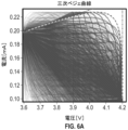
この実施例では、以下の実験を実施した:32セルをMaccorサイクラーに接続し(詳細については参照セクションを参照)、16セルは部分的に経年劣化したものであり(平均Nサイクル/セル)、16セルは新しいものであった(0サイクル/セル)。探索空間は、各セルの充電プロファイルを指定した、三次ベジェ関数として定義されるスプライン曲線の一群からなっていた(定義に関する参照を参照)。実施の目的で、これらの充電曲線を5つの定電流充電工程に分割した。スタートポイント(200mAで最大3.6Vの定電流)及びエンドポイント(100mAで最大4.2Vの定電流)を両方固定し、充電プロファイルの終了時に追加の定電圧工程(V=4.2V、カットオフ電流=25mA)を加えて、実際に一般的に行われるように、各セルがその全容量に到達することを確実にした。4つの独立変数は、三次ベジェ関数の2つのコントロールポイントの2つの座標(カットオフ電圧:V、及び定電流:I)からなっていた。各独立変数を8つのレベルに分割し、合計4096の可能な組み合わせを得た。完全に充電されると、セルを固定放電プロファイル(250mAで3Vまでの定電流)下で放電させた。 In this example, the following experiments were performed: 32 cells were connected to a Maccor cycler (see reference section for details), 16 cells were partially aged (average N cycles/cell); 16 cells were new (0 cycles/cell). The search space consisted of a family of spline curves defined as cubic Bezier functions that specified the charging profile of each cell (see reference for definition). For implementation purposes, these charging curves were divided into five galvanostatic charging steps. Both the start point (constant current up to 3.6 V at 200 mA) and end point (constant current up to 4.2 V at 100 mA) are fixed, and an additional constant voltage step (V = 4.2 V, cut Off-current = 25 mA) was applied to ensure that each cell reached its full capacity, as is commonly done in practice. The four independent variables consisted of two coordinates of two control points of a cubic Bezier function (cutoff voltage: V, and constant current: I). Each independent variable was divided into eight levels, resulting in a total of 4096 possible combinations. Once fully charged, the cell was discharged under a fixed discharge profile (constant current to 3V at 250 mA).
本発明者らは、主に例示及び簡潔さの目的で充電プロファイルに焦点を当て、開示された方法は、放電プロファイル、並びにセルサイクルに関連する任意の他の変数に拡張することができる。性能指数(figure of merit、FOM)は、放電エネルギーをサイクル時間(すなわち、充電時間+放電時間)で割ったものとして計算された送達電力として定義された。セルの著しい経時劣化の前に、放電エネルギー及び放電時間の両方は、セル(又はサイクル)にわたってほぼ一定であり、FOMは主に充電時間によって変化した。充電エネルギー及び充電時間を含む各サイクルで、追加の従属変数を記録した。外部変数もまた、各サイクルで記録されて、従属変数の可能性のある効果を探索し、クラスタリング機会を見つけ出す。外部変数は、セル識別(ID)、古いセル対新しいセル、放電エネルギー、及び放電時間を含んでいた。 We primarily focus on charge profiles for purposes of illustration and brevity, and the disclosed method can be extended to discharge profiles as well as any other variables related to cell cycling. The figure of merit (FOM) was defined as the delivered power calculated as the discharge energy divided by the cycle time (ie, charge time + discharge time). Before significant aging of the cell, both discharge energy and discharge time were approximately constant across the cell (or cycle), and the FOM varied primarily with charge time. Additional dependent variables were recorded at each cycle including charging energy and charging time. Extrinsic variables are also recorded at each cycle to explore possible effects of the dependent variable and find clustering opportunities. External variables included cell identification (ID), old versus new cells, discharge energy, and discharge time.
データを数週間にわたって記録した。最初の探索フェーズの間、アルゴリズムは、探索空間にわたってランダムに充電プロファイルを割り当て、FOM上の各IVレベルの予想される因果的効果の周囲に信頼区間(confidence interval、CI)を構築した。総探索空間の約30%の探索の後に生じたCIのうちの一部が有意に区別され、重なり合わないと、アルゴリズムは、最も高い効用でより頻繁にレベルを割り当てることによって、その知識を利用し始め、FOMの漸進的な増加をもたらす。アルゴリズムはまた、統計的に異なる因果的効果にわたってクラスターを識別することも開始した。最適レベルはクラスターにわたって変化しない場合があるが、それらの相対的効果は、経時劣化の差及び健康の初期状態の差に起因して変化した。 Data was recorded over several weeks. During the initial search phase, the algorithm randomly assigned charging profiles across the search space and constructed a confidence interval (CI) around the expected causal effect of each IV level on the FOM. If some of the CIs that result after searching approximately 30% of the total search space are significantly distinct and do not overlap, the algorithm exploits that knowledge by assigning levels more frequently with the highest utility. , resulting in a gradual increase in FOM. The algorithm also began to identify clusters across statistically distinct causal effects. Although the optimal levels may not vary across clusters, their relative effectiveness varied due to differences in aging and differences in initial state of health.
図6A~図6Dは、説明した実施例の全ての可能な充電プロファイルの探索空間を示す。図6Aでは、最適な充電プロファイルは、破線として示されており、そのエンドポイント及び制御ハンドルポイントは、一点鎖線として示されている。選択されたFOM(総送達電力)は、放電エネルギーに対してプロットされる。最適な充電プロファイルに関連する電力値は、暗い灰色の円として示される。FOM及び利用周波数はまた、時間の関数としてプロットされる。図6Aは、全ての可能な充電プロファイルの探索空間を示す。図6Bは、放電エネルギーに対するFOMを示す。図6Cは、時間に対するFOMを示す。図6Dは、利用周波数を示す。 6A-6D illustrate the search space of all possible charging profiles for the described embodiments. In FIG. 6A, the optimal charging profile is shown as a dashed line, and its endpoints and control handle points are shown as dash-dotted lines. The selected FOM (total delivered power) is plotted against the discharge energy. The power values associated with the optimal charging profile are shown as dark gray circles. FOM and utilized frequency are also plotted as a function of time. FIG. 6A shows the search space of all possible charging profiles. FIG. 6B shows the FOM versus discharge energy. FIG. 6C shows the FOM versus time. FIG. 6D shows the frequencies used.
図7A~図7Cは、アルゴリズムが、新しいセルに対する古いセルの効果サイズの違いを特定したことを経時的に示す。クラスタリングが開始されると、アルゴリズムは、別個のクラスターごとに最適な電荷プロファイルを利用し、これは、クラスターにわたって同じであっても同じでなくてもよい。図7A及び図7Bは、送達電力を最大化するための方法の例を示し、E-Capはエネルギー容量を指す。図7Cは、環境条件下で送達電力を最大化するための方法の例を示す。 7A-7C show that the algorithm identified differences in the effect size of old cells relative to new cells over time. Once clustering is initiated, the algorithm utilizes the optimal charge profile for each distinct cluster, which may or may not be the same across clusters. 7A and 7B show an example of a method for maximizing delivered power, where E-Cap refers to energy capacity. FIG. 7C shows an example of a method for maximizing delivered power under environmental conditions.
セル内部抵抗を測定する方法
以前の実験からのデータも分析して、各サイクル中及び経時的にセルの内部抵抗を特徴付けた。電流及び充電状態(state of charge、SOC)の関数として内部抵抗をマッピングすることは、典型的には、様々なレートで完全なサイクルを実行することによって達成することができる。この分析は時間がかかり、更に、セルの寿命の開始時の内部抵抗のみを表す。この分析はまた、1回のサイクルの結果が以前のサイクルとは無関係ではないため、不正確であり得る。本明細書に開示されるアルゴリズムでランダム化することにより、この効果は軽減される。
Method of Measuring Cell Internal Resistance Data from previous experiments were also analyzed to characterize the internal resistance of the cell during each cycle and over time. Mapping internal resistance as a function of current and state of charge (SOC) can typically be accomplished by performing complete cycles at various rates. This analysis is time consuming and furthermore represents only the internal resistance at the beginning of the cell's life. This analysis can also be inaccurate because the results of one cycle are not independent of previous cycles. Randomization with the algorithms disclosed herein alleviates this effect.
ここで、実際の各サイクルからのデータを使用して、以下の方法で内部抵抗を推定した:各定電流工程では、内部抵抗値をR=ΔV/ΔIで近似し、ここで、ΔVは、25mAでサイクルされた基準セルと比較した平均電位の変化であり、ΔIは、基準セルと比較した電流差であった。各セルについてRを推定し、各サイクル及び5つの定電流工程のそれぞれについて推定した。充電状態に対する内部抵抗のほぼ連続曲線が得られ、リチウムイオンバッテリの期待される挙動を示している。これらの結果を図8A~図8Cに示す。 Here, data from each actual cycle was used to estimate the internal resistance in the following way: For each constant current step, the internal resistance value was approximated by R = ΔV/ΔI, where ΔV is was the change in average potential compared to a reference cell cycled at 25 mA, and ΔI was the current difference compared to the reference cell. R was estimated for each cell and for each cycle and each of the five galvanostatic steps. A nearly continuous curve of internal resistance versus state of charge is obtained, indicating the expected behavior of a lithium-ion battery. These results are shown in FIGS. 8A to 8C.
図8Aは、基準C/20電荷プロファイル(破線)に対するアルゴリズム(実線)によって割り当てられた充電プロファイルに対する電圧対容量を示し、過電圧ΔVが図示されている。図8Bは、SOC及び過電圧対電流を示す。図8Cは、SOCに対する内部抵抗を示す。 FIG. 8A shows voltage versus capacity for the charging profile assigned by the algorithm (solid line) versus the reference C/20 charge profile (dashed line), with overvoltage ΔV illustrated. FIG. 8B shows SOC and overvoltage versus current. FIG. 8C shows the internal resistance for SOC.
経時的なその場での内部抵抗の知識を使用して、有意な過電圧及び不足電圧、セルの加熱及び劣化をもたらす可能性がある探索空間内の充電プロファイルを排除することによって、バッテリ管理システムの性能及び安全性を改善することができる。内部抵抗マップは、データ内のサブグループから構築することができ、可能なサブグループの例としては、セル使用年数、サイクル数、温度曝露、累積放電エネルギー、平均放電電流、平均充電電流、最大充電電流、平均電圧、製造バッチが挙げられるが、これらに限定されない。内部抵抗の変化はまた、バッテリパック内の短絡の発生などの異常な状態を検出するために使用することができる。 of battery management systems by using knowledge of in-situ internal resistance over time to eliminate charging profiles within the search space that can result in significant over- and under-voltage, cell heating and degradation. Performance and safety can be improved. Internal resistance maps can be constructed from subgroups within the data; examples of possible subgroups include cell age, number of cycles, temperature exposure, cumulative discharge energy, average discharge current, average charge current, maximum charge Examples include, but are not limited to, current, average voltage, and manufacturing batch. Changes in internal resistance can also be used to detect abnormal conditions, such as the occurrence of a short circuit within a battery pack.
パック内のセルのバランスをとる方法
電力を最大化するだけでなく、セル電力に対する充電プロファイル変数の影響の因果知識を使用して、健康状態(SOH)又はセル全体の内部抵抗などのバランシングなど他の効用指標を最適化することもできる。バッテリの経年劣化は、バッテリ寿命の開始時は(製造公差内で)かなり均一である傾向があるが、更なる充電/放電サイクルの各々により、ますます不均質かつ予測不可能になる。これは、あまり厳しくない用途においてそれらの寿命を延長するための方法として、新しい用途のために使用済みセルを再パッキングする際の重要な考慮事項である。一例は、グリッドレベルエネルギー貯蔵用のEVバッテリを再使用することである。セルの経時劣化のバランスをとることができるスマートバッテリ管理システムの開発は、安全で信頼性の高い耐久性のある動作を確実にし、アプリケーションを経済的に実行可能にするために重要である。各セルの内部抵抗、並びに均質なセルグループにわたるクラスタリングの正確な判定は、実際にセルのバランシングを定量的に実施するための有効なメカニズムである。
How to balance cells in a pack Not only to maximize power, but also to balance other factors such as state of health (SOH) or internal resistance across cells using causal knowledge of the effects of charging profile variables on cell power. It is also possible to optimize the utility index of Battery aging tends to be fairly uniform (within manufacturing tolerances) at the beginning of battery life, but becomes increasingly heterogeneous and unpredictable with each additional charge/discharge cycle. This is an important consideration when repacking used cells for new applications as a way to extend their lifetime in less demanding applications. One example is reusing EV batteries for grid-level energy storage. The development of smart battery management systems that can balance cell aging is important to ensure safe, reliable and durable operation and to make applications economically viable. Accurate determination of the internal resistance of each cell as well as clustering across a homogeneous group of cells is an effective mechanism for quantitatively performing cell balancing in practice.
同様に、ハイブリッド自動車は、異なる性能及び経時劣化特性を有する異なる種類のセルを組み合わせるシステムを使用することができる。電力グリッドは、高電力及び高エネルギー貯蔵を組み合わせるシステムを使用することができる。これは、データのより大きな分散につながり、バッテリ管理のための標準的なデータ分析技術を適用することがより困難になる。本明細書に開示されるアルゴリズムは、経時的な信頼性の高い因果推論に使用することができる均質なクラスターの最小セットを自動的に識別することによって、この種類の問題に対処することができる。本明細書に開示されるアルゴリズムはまた、異なる自動車にわたってバッテリ上で実験を実施するために使用することができる。 Similarly, hybrid vehicles may use systems that combine different types of cells with different performance and aging characteristics. Power grids can use systems that combine high power and high energy storage. This leads to a greater dispersion of data and makes it more difficult to apply standard data analysis techniques for battery management. The algorithms disclosed herein can address this type of problem by automatically identifying a minimal set of homogeneous clusters that can be used for reliable causal inference over time. . The algorithms disclosed herein can also be used to perform experiments on batteries across different vehicles.
異なる環境条件下で送達された電力を最大化する方法
多くの用途では、バッテリは、天気、不定期の動作などにより、異なる環境条件に晒される。例示の目的で、本発明者らは、外部因子として周囲温度に焦点を当てた。これは、多くの用途に一般的であり、セル性能の大きな既知の効果を有する。本発明者らは、45℃の高温周囲温度下でオーブン内に配置された8個のセルを有する実験の第2のセットを実施した。結果は、最適な電荷プロファイルが環境条件によってどのように変化するかを示した。
How to Maximize Power Delivered under Different Environmental Conditions In many applications, batteries are exposed to different environmental conditions due to weather, occasional operation, etc. For purposes of illustration, we focused on ambient temperature as an external factor. This is common in many applications and has a large known effect on cell performance. We conducted a second set of experiments with 8 cells placed in an oven under an elevated ambient temperature of 45°C. The results showed how the optimal charge profile varies with environmental conditions.
実施例の参照
セル:充電式リチウムイオンポリマーバッテリ巻回パウチセル、5.0×30×35mm、公称容量500mAh;黒鉛アノード及びLiCoO2カソード(E-Group,Mt.Laurel,New Jersey)。
Reference to Examples Cell: Rechargeable lithium ion polymer battery wound pouch cell, 5.0 x 30 x 35 mm, nominal capacity 500 mAh; graphite anode and LiCoO 2 cathode (E-Group, Mt. Laurel, New Jersey).
Maccor:96チャンネル、シリーズ4000 Maccor(Tulsa,Oklahoma)。 Maccor: 96 channels, series 4000 Maccor (Tulsa, Oklahoma).
三次ベジェ関数:
平面又はより高次元空間の4つの点P0、P1、P2、及びP3は、三次ベジェ曲線を画定する。曲線は、P0で始まり、P1に向かい、P2の方向からP3に到達する。通常、曲線は、P1又はP2を通過せず、これらの点は、方向情報を提供するためにのみ存在する。P1とP2との間の距離は、曲線がP2に向かう前にP1に向かって「どれくらいの距離」及び「どれくらいの速さ」で移動するかを決定する。
Cubic Bezier function:
The four points P 0 , P 1 , P 2 and P 3 in a plane or higher dimensional space define a cubic Bezier curve. The curve starts at P 0 , goes towards P 1 and reaches P 3 from the direction of P 2 . Typically, the curve does not pass through P 1 or P 2 ; these points exist only to provide directional information. The distance between P 1 and P 2 determines how far and how fast the curve moves towards P 1 before heading towards P 2 .
Pi、Pj、及びPkによって定義された二次ベジェ曲線のBPi,Pj,Pk(t)を書いて、三次ベジェ曲線は、2つの二次ベジェ曲線のアフィン結合として定義することができる。
B(t)=(1-t)BP0,P1,P2(t)+tBP1,P2,P3(t),0≦t≦1
Writing B Pi, Pj, Pk (t) of a quadratic Bezier curve defined by P i , P j , and P k , a cubic Bezier curve can be defined as an affine combination of two quadratic Bezier curves. can.
B(t)=(1-t)B P0, P1, P2 (t)+tB P1, P2, P3 (t), 0≦t≦1
曲線の明示的な形態は、以下である。
B(t)=(1-t)3P0+3(1-t)2tP1+3(1-t)t2P2+t3P3,0≦t≦1
The explicit form of the curve is:
B(t)=(1-t) 3 P 0 +3(1-t) 2 tP 1 +3(1-t)t 2 P 2 +t 3 P 3 ,0≦t≦1
P1及びP2のいくつかの選択肢については、曲線はそれ自体と交差してもよく、又は尖点を含んでもよい。
なお、以上の各実施形態に加えて以下の態様について付記する。
(付記1)
アクティブバッテリ管理のための方法であって、
バッテリの充電又は放電中にランダム化され制御された信号を注入する工程と、
正常動作範囲及び制約内で前記信号注入が起こることを保証する工程と、
前記制御された信号に応答して前記バッテリの性能を監視する工程と、
前記バッテリ性能と前記制御された信号との間の因果関係についての信頼区間を計算する工程と、
前記計算された信頼区間に基づいて前記バッテリの前記充電又は放電の最適信号を選択する工程と、を含む、方法。
(付記2)
前記制御された信号が、充電プロファイル又は放電プロファイルを含む、付記1に記載の方法。
(付記3)
前記制御された信号が、充電レート又は放電レートを含む、付記1に記載の方法。
(付記4)
前記制御された信号が、充電プロファイルエンドポイント又は放電プロファイルエンドポイントを含む、付記1に記載の方法。
(付記5)
前記正常動作範囲が、制御情報及び動作制約に基づいて生成された可能な制御状態の多次元空間を含む、付記1に記載の方法。
(付記6)
前記選択する工程が、環境条件を含む外部データに基づいて前記最適信号を選択することを更に含む、付記1に記載の方法。
(付記7)
前記環境条件が、前記バッテリの周囲の温度、湿度、又は気流のうちの少なくとも1つを含む、付記6に記載の方法。
(付記8)
前記選択する工程が、ポータブル電子デバイス、アプリケーションの使用、ユーザ設定、スケジュールされたイベント若しくはアラーム、電力消費パターン、時刻、又は前記デバイスの場所に関して、これらのうちの少なくとも1つを含む外部データに基づいて前記最適信号を選択することを更に含む、付記1に記載の方法。
(付記9)
前記バッテリがバッテリのパックを含む、付記1に記載の方法。
(付記10)
アクティブバッテリ管理のための方法であって、
バッテリの充電又は放電のための信号注入を提供する工程と、
前記信号注入に対応する応答信号を受信する工程と、
前記応答信号の効用を測定する工程と、
前記バッテリの充電又は放電に関するデータにアクセスする工程と、
前記応答信号の前記効用に基づいて前記データを修正する工程と、を含む、方法。
(付記11)
前記信号注入が、充電プロファイル又は放電プロファイルを含む、付記10に記載の方法。
(付記12)
前記信号注入が、充電レート又は放電レートを含む、付記10に記載の方法。
(付記13)
前記信号注入が、充電プロファイルエンドポイント又は放電プロファイルエンドポイントを含む、付記10に記載の方法。
(付記14)
前記アクセスする工程が、ルックアップテーブルにアクセスすることを含む、付記10に記載の方法。
(付記15)
前記信号注入が、空間的到達範囲を有する、付記10に記載の方法。
(付記16)
前記信号注入が、時間的到達範囲を有する、付記10に記載の方法。
(付記17)
前記修正する工程が、環境条件を含む外部データに基づいて前記データを修正することを更に含む、付記10に記載の方法。
(付記18)
前記環境条件が、前記バッテリの周囲の温度、湿度、又は気流のうちの少なくとも1つを含む、付記17に記載の方法。
(付記19)
前記選択する工程が、ポータブル電子デバイス、アプリケーションの使用、ユーザ設定、スケジュールされたイベント若しくはアラーム、電力消費パターン、時刻、又は前記デバイスの場所に関して、これらのうちの少なくとも1つを含む外部データに基づいて前記最適信号を選択することを更に含む、付記10に記載の方法。
(付記20)
前記バッテリがバッテリのパックを含む、付記10に記載の方法。
For some options of P 1 and P 2 , the curve may intersect itself or include a cusp.
In addition to the above embodiments, the following aspects will be added.
(Additional note 1)
A method for active battery management, the method comprising:
injecting a randomized controlled signal during charging or discharging of the battery;
ensuring that the signal injection occurs within normal operating ranges and constraints;
monitoring performance of the battery in response to the controlled signal;
calculating a confidence interval for a causal relationship between the battery performance and the controlled signal;
selecting an optimal signal for charging or discharging the battery based on the calculated confidence interval.
(Additional note 2)
10. The method of claim 1, wherein the controlled signal includes a charging profile or a discharging profile.
(Additional note 3)
10. The method of claim 1, wherein the controlled signal includes a charge rate or a discharge rate.
(Additional note 4)
The method of clause 1, wherein the controlled signal includes a charging profile endpoint or a discharging profile endpoint.
(Appendix 5)
2. The method of claim 1, wherein the normal operating range includes a multidimensional space of possible control states generated based on control information and operating constraints.
(Appendix 6)
2. The method of claim 1, wherein the selecting step further comprises selecting the optimal signal based on external data including environmental conditions.
(Appendix 7)
7. The method of clause 6, wherein the environmental conditions include at least one of temperature, humidity, or airflow surrounding the battery.
(Appendix 8)
The selecting step is based on external data including at least one of the following regarding the portable electronic device, application usage, user settings, scheduled events or alarms, power consumption patterns, time of day, or location of the device. 1. The method of claim 1, further comprising selecting the optimal signal using a method.
(Appendix 9)
The method of clause 1, wherein the battery comprises a pack of batteries.
(Appendix 10)
A method for active battery management, the method comprising:
providing signal injection for charging or discharging the battery;
receiving a response signal corresponding to the signal injection;
measuring the utility of the response signal;
accessing data regarding charging or discharging the battery;
modifying the data based on the utility of the response signal.
(Appendix 11)
11. The method of
(Appendix 12)
11. The method of
(Appendix 13)
11. The method of
(Appendix 14)
11. The method of
(Appendix 15)
11. The method of
(Appendix 16)
11. The method of
(Appendix 17)
11. The method of
(Appendix 18)
18. The method of clause 17, wherein the environmental conditions include at least one of temperature, humidity, or airflow surrounding the battery.
(Appendix 19)
The selecting step is based on external data including at least one of the following regarding the portable electronic device, application usage, user settings, scheduled events or alarms, power consumption patterns, time of day, or location of the device. 11. The method according to
(Additional note 20)
11. The method of
Claims (7)
バッテリの充電又は放電中にランダム化され制御された信号を注入する工程と、
正常動作範囲及び制約内で前記信号注入が起こることを保証する工程と、
前記制御された信号に応答して前記バッテリの性能を監視する工程と、
前記バッテリ性能と前記制御された信号との間の因果関係についての信頼区間を計算する工程と、
前記計算された信頼区間に基づいて前記バッテリの前記充電又は放電の最適信号を選択する工程と、を含む、方法。 A method for active battery management, the method comprising:
injecting a randomized controlled signal during charging or discharging of the battery;
ensuring that the signal injection occurs within normal operating ranges and constraints;
monitoring performance of the battery in response to the controlled signal;
calculating a confidence interval for a causal relationship between the battery performance and the controlled signal;
selecting an optimal signal for charging or discharging the battery based on the calculated confidence interval.
バッテリの充電又は放電のための信号注入を提供する工程と、
前記信号注入に対応する応答信号を受信する工程と、
前記応答信号の効用を測定する工程と、
前記バッテリの充電又は放電に関するデータにアクセスする工程と、
前記応答信号の前記効用に基づいて前記データを修正する工程と、を含む、方法。 A method for active battery management, the method comprising:
providing signal injection for charging or discharging the battery;
receiving a response signal corresponding to the signal injection;
measuring the utility of the response signal;
accessing data regarding charging or discharging the battery;
modifying the data based on the utility of the response signal .
Applications Claiming Priority (3)
| Application Number | Priority Date | Filing Date | Title |
|---|---|---|---|
| US201862729598P | 2018-09-11 | 2018-09-11 | |
| US62/729,598 | 2018-09-11 | ||
| PCT/IB2019/057409 WO2020053702A1 (en) | 2018-09-11 | 2019-09-03 | Active battery management method |
Publications (3)
| Publication Number | Publication Date |
|---|---|
| JP2022500994A JP2022500994A (en) | 2022-01-04 |
| JP2022500994A5 JP2022500994A5 (en) | 2022-09-12 |
| JP7361122B2 true JP7361122B2 (en) | 2023-10-13 |
Family
ID=69777670
Family Applications (2)
| Application Number | Title | Priority Date | Filing Date |
|---|---|---|---|
| JP2021537523A Active JP7361122B2 (en) | 2018-09-11 | 2019-09-03 | Active battery management method |
| JP2021538167A Active JP7731286B2 (en) | 2018-09-11 | 2019-09-10 | Active Battery Management Methods for Economic Optimization |
Family Applications After (1)
| Application Number | Title | Priority Date | Filing Date |
|---|---|---|---|
| JP2021538167A Active JP7731286B2 (en) | 2018-09-11 | 2019-09-10 | Active Battery Management Methods for Economic Optimization |
Country Status (5)
| Country | Link |
|---|---|
| US (3) | US20210190868A1 (en) |
| EP (2) | EP3850385A4 (en) |
| JP (2) | JP7361122B2 (en) |
| CN (3) | CN112703412A (en) |
| WO (2) | WO2020053702A1 (en) |
Families Citing this family (13)
| Publication number | Priority date | Publication date | Assignee | Title |
|---|---|---|---|---|
| JP7361122B2 (en) | 2018-09-11 | 2023-10-13 | スリーエム イノベイティブ プロパティズ カンパニー | Active battery management method |
| JP6896793B2 (en) * | 2019-05-27 | 2021-06-30 | 本田技研工業株式会社 | Information processing device |
| DE102019216015A1 (en) * | 2019-10-17 | 2021-04-22 | Robert Bosch Gmbh | Method of adjusting an anode overvoltage of a lithium-ion battery, method of improving a capacity aging condition of the lithium-ion battery |
| DE102020212236A1 (en) * | 2020-09-29 | 2022-03-31 | Robert Bosch Gesellschaft mit beschränkter Haftung | Method and device for operating a system for providing aging states of electrical energy storage devices for a large number of devices using machine learning methods |
| CN115556610A (en) * | 2021-07-01 | 2023-01-03 | 沃尔沃汽车公司 | Vehicle-to-vehicle charging system and method |
| US11443569B1 (en) * | 2021-10-30 | 2022-09-13 | Beta Air, Llc | Systems and methods for battery management for a vehicle |
| WO2023102265A1 (en) * | 2021-12-03 | 2023-06-08 | Sustainable Energy Technologies, Inc. | System and method for energy management of a power pack for an electric vehicle including photovoltaic charging |
| US12179608B2 (en) | 2021-12-03 | 2024-12-31 | Sustainable Energy Technologies, Inc. | Monitoring and managing temperature of power packs |
| WO2023107514A1 (en) | 2021-12-06 | 2023-06-15 | Sustainable Energy Technologies, Inc. | System and method for analyzing temperature changes in supercapacitor battery storage for electric vehicle |
| US12296721B2 (en) | 2021-12-10 | 2025-05-13 | Sustainable Energy Technologies, Inc. | Method and systems to trickle charge electric vehicle's supercapacitors using solar energy |
| CN114660478B (en) * | 2022-05-12 | 2022-09-02 | 中创新航科技股份有限公司 | Battery device, detection method thereof, screening method and screening device for battery cells |
| KR102769183B1 (en) * | 2022-06-13 | 2025-02-14 | 연세대학교 산학협력단 | Method and Device for analyzing of secondary battery life |
| WO2024187166A1 (en) * | 2023-03-08 | 2024-09-12 | Lifetime Energy Inc. | System and method of determining economic decisions based on lifetime performance of a battery by a real-time battery management system |
Citations (2)
| Publication number | Priority date | Publication date | Assignee | Title |
|---|---|---|---|---|
| JP2000266791A (en) | 1999-03-13 | 2000-09-29 | Korea Kumho Petrochem Co Ltd | Method and apparatus for measuring Laplace transform impedance |
| WO2017183238A1 (en) | 2016-04-22 | 2017-10-26 | ソニー株式会社 | Charging-discharging control device, charging-discharging control method, battery pack, electronic instrument, electric car, electric tool and electric power storage system |
Family Cites Families (37)
| Publication number | Priority date | Publication date | Assignee | Title |
|---|---|---|---|---|
| JP3379298B2 (en) * | 1995-08-30 | 2003-02-24 | 新神戸電機株式会社 | Device for determining the life of sealed lead-acid batteries |
| JP2002505747A (en) * | 1997-06-19 | 2002-02-19 | スナップ−オン イクイップメント リミテッド | Battery inspection and classification |
| US6374251B1 (en) * | 1998-03-17 | 2002-04-16 | Microsoft Corporation | Scalable system for clustering of large databases |
| JPH11289676A (en) * | 1998-04-01 | 1999-10-19 | Toyo System Kk | Power supply for secondary battery charging / discharging device |
| AU2001273306A1 (en) * | 2000-07-05 | 2002-01-14 | Camo, Inc. | Method and system for the dynamic analysis of data |
| US6653817B2 (en) * | 2001-06-26 | 2003-11-25 | General Motors Corporation | State-of-charge detection device for a battery |
| US6555991B1 (en) | 2002-02-05 | 2003-04-29 | Andrew Michael Zettel | Battery operating condition dependent method and apparatus for controlling energy transfer between an energy bus and a system of batteries |
| US7590642B2 (en) * | 2002-05-10 | 2009-09-15 | Oracle International Corp. | Enhanced K-means clustering |
| CN1862279B (en) | 2005-05-11 | 2010-04-28 | 苏州润源电气技术有限公司 | Method for estimating aging rate and testing fault of battery, and apparatus for managing and monitoring battery |
| CN1975444A (en) | 2005-11-28 | 2007-06-06 | 孙斌 | Accumulator cell internal resistance and degradation state on-line monitoring method and system |
| DE102006005334B4 (en) * | 2006-02-07 | 2022-12-22 | Bayerische Motoren Werke Aktiengesellschaft | Method for monitoring and/or controlling or regulating the voltage of at least one cell group in a cell assembly of an energy store, as well as cell group logic and central logic for carrying out the method |
| JP5363740B2 (en) * | 2008-01-31 | 2013-12-11 | パナソニック株式会社 | Charge control circuit, battery pack, and charging system |
| JP5098912B2 (en) * | 2008-07-11 | 2012-12-12 | ソニー株式会社 | Battery pack and charge control system |
| KR101288652B1 (en) * | 2009-10-09 | 2013-07-22 | 주식회사 엘지화학 | Battery charging system and charging method |
| US8564246B2 (en) | 2010-03-30 | 2013-10-22 | Grrreen, Inc. | Battery charging system and method |
| AU2011316798B2 (en) * | 2010-10-22 | 2017-02-02 | Nucleus Scientific, Inc. | Apparatus and method for rapidly charging batteries |
| CN102545280A (en) * | 2010-12-16 | 2012-07-04 | 鸿富锦精密工业(深圳)有限公司 | Charging circuit |
| US8838510B2 (en) * | 2011-09-16 | 2014-09-16 | International Business Machines Corporation | Choosing pattern recognition algorithms and data features using a genetic algorithm |
| KR20150004376A (en) * | 2012-04-12 | 2015-01-12 | 이스트 펜 매뉴팩츄어링 컴퍼니 | Management of battery capacity |
| US8963494B2 (en) * | 2012-05-18 | 2015-02-24 | Tesla Motors, Inc. | Charge rate optimization |
| US20140097787A1 (en) | 2012-10-09 | 2014-04-10 | Yi-Ming Lin | Active battery management system for a battery pack |
| KR20140094362A (en) * | 2013-01-22 | 2014-07-30 | 한국전자통신연구원 | Apparatus and method for energy management of the electric vehicle |
| US9476946B2 (en) * | 2013-05-08 | 2016-10-25 | GM Global Technology Operations LLC | SOC determination by evaluation of effects invoked by dimensional changes of battery cells |
| US9770997B2 (en) * | 2013-06-11 | 2017-09-26 | Ford Global Technologies, Llc | Detection of imbalance across multiple battery cells measured by the same voltage sensor |
| AU2015241029B2 (en) * | 2014-03-31 | 2018-02-01 | Ingrain, Inc. | Representative elementary volume determination via clustering-based statistics |
| US20150372279A1 (en) | 2014-06-24 | 2015-12-24 | Turboroto Inc. | Active battery stack system and method |
| WO2016115002A1 (en) * | 2015-01-16 | 2016-07-21 | 3M Innovative Properties Company | Systems and methods for selecting grid actions to improve grid outcomes |
| CN105005005B (en) * | 2015-08-10 | 2017-10-13 | 东南大学 | A kind of batteries deteriorate cell detection method |
| US20170045902A1 (en) | 2015-08-14 | 2017-02-16 | Nec Laboratories America, Inc. | Control strategies for grid scale storage operation in frequency regulation markets considering battery health factors |
| US10298042B2 (en) * | 2016-02-05 | 2019-05-21 | Nec Corporation | Resilient battery charging strategies to reduce battery degradation and self-discharging |
| CN107528337A (en) * | 2016-11-21 | 2017-12-29 | 六安市科宇专利技术开发服务有限公司 | A kind of electric automobile charging station with energy-storage system |
| US10193369B2 (en) * | 2017-01-05 | 2019-01-29 | Gbatteries Energy Canada Inc. | Active battery management system |
| CN107453408B (en) * | 2017-07-18 | 2020-05-08 | 广东双新电气科技有限公司 | Micro-grid energy optimization scheduling method considering uncertainty |
| US11691518B2 (en) * | 2017-07-21 | 2023-07-04 | Quantumscape Battery, Inc. | Predictive model for estimating battery states |
| US10992156B2 (en) * | 2017-10-17 | 2021-04-27 | The Board Of Trustees Of The Leland Stanford Junior University | Autonomous screening and optimization of battery formation and cycling procedures |
| JP7361122B2 (en) | 2018-09-11 | 2023-10-13 | スリーエム イノベイティブ プロパティズ カンパニー | Active battery management method |
| US20220172139A1 (en) | 2019-03-15 | 2022-06-02 | 3M Innovative Properties Company | Operating a supply chain using causal models |
-
2019
- 2019-09-03 JP JP2021537523A patent/JP7361122B2/en active Active
- 2019-09-03 WO PCT/IB2019/057409 patent/WO2020053702A1/en not_active Ceased
- 2019-09-03 US US17/272,824 patent/US20210190868A1/en active Pending
- 2019-09-03 EP EP19860886.1A patent/EP3850385A4/en active Pending
- 2019-09-03 CN CN201980058914.4A patent/CN112703412A/en not_active Withdrawn
- 2019-09-10 CN CN201980058878.1A patent/CN112673509B/en active Active
- 2019-09-10 EP EP19860879.6A patent/EP3850700A4/en not_active Withdrawn
- 2019-09-10 WO PCT/US2019/050281 patent/WO2020055778A1/en not_active Ceased
- 2019-09-10 US US17/274,307 patent/US12092694B2/en active Active
- 2019-09-10 CN CN202510122862.XA patent/CN119944132A/en active Pending
- 2019-09-10 JP JP2021538167A patent/JP7731286B2/en active Active
-
2024
- 2024-09-04 US US18/824,176 patent/US20240426921A1/en active Pending
Patent Citations (2)
| Publication number | Priority date | Publication date | Assignee | Title |
|---|---|---|---|---|
| JP2000266791A (en) | 1999-03-13 | 2000-09-29 | Korea Kumho Petrochem Co Ltd | Method and apparatus for measuring Laplace transform impedance |
| WO2017183238A1 (en) | 2016-04-22 | 2017-10-26 | ソニー株式会社 | Charging-discharging control device, charging-discharging control method, battery pack, electronic instrument, electric car, electric tool and electric power storage system |
Also Published As
| Publication number | Publication date |
|---|---|
| CN112673509B (en) | 2025-02-18 |
| US20210190868A1 (en) | 2021-06-24 |
| CN112703412A (en) | 2021-04-23 |
| US12092694B2 (en) | 2024-09-17 |
| WO2020053702A1 (en) | 2020-03-19 |
| CN119944132A (en) | 2025-05-06 |
| EP3850385A4 (en) | 2022-06-29 |
| CN112673509A (en) | 2021-04-16 |
| WO2020055778A1 (en) | 2020-03-19 |
| US20210336471A1 (en) | 2021-10-28 |
| EP3850385A1 (en) | 2021-07-21 |
| EP3850700A1 (en) | 2021-07-21 |
| JP7731286B2 (en) | 2025-08-29 |
| JP2022500994A (en) | 2022-01-04 |
| JP2022500995A (en) | 2022-01-04 |
| US20240426921A1 (en) | 2024-12-26 |
| EP3850700A4 (en) | 2022-07-27 |
Similar Documents
| Publication | Publication Date | Title |
|---|---|---|
| JP7361122B2 (en) | Active battery management method | |
| US11598818B2 (en) | Determination of the aging of an electric storage system | |
| CN113064089B (en) | Internal resistance detection method, device, medium and system of power battery | |
| US9846886B2 (en) | Strategic modeling for economic optimization of grid-tied energy assets | |
| KR102634816B1 (en) | An battery monitoring apparatus detecting charge balance of a battery and a method thereof | |
| WO2024060537A1 (en) | Method and system for early warning of abnormal self-discharge of battery, and electronic device and storage medium | |
| KR102832250B1 (en) | Method of detecting abnormal battery cell | |
| US20160003917A1 (en) | Method and apparatus for estimating state of battery | |
| JP2017069011A (en) | Life-controlled secondary battery system | |
| US11656293B2 (en) | Method and apparatus for parameterizing an electrochemical battery model for a battery based on data from a plurality of batteries | |
| US20160144736A1 (en) | Method for Battery Management and Battery Management System | |
| CN103051005A (en) | Battery charging and discharging management system and method | |
| CN116488219A (en) | A distributed energy storage acquisition strategy control method based on multi-level architecture | |
| CN115966792A (en) | Method and device for performing a charging process of a device battery | |
| CN119099405A (en) | New energy automobile charging control method and system based on neural network and big data | |
| CN120214586A (en) | Battery power prediction method, device, storage medium and electronic device | |
| CN114460484A (en) | Rechargeable battery service life prediction method and device based on accumulated loss | |
| CN118944238A (en) | A new energy storage lithium battery control system and control method | |
| Xia et al. | State of Health Estimation for Lithium-Ion Batteries Based on Improved Support Vector Regression | |
| EP4545989A1 (en) | Method and system for calculating battery state of charge | |
| CN120178036A (en) | Method and device for determining model parameters and internal battery states of an electrochemical battery model of a device battery of a technical device | |
| WO2025139114A1 (en) | Battery capacity determination method, battery capacity determination apparatus, and electric device | |
| Pop et al. | Battery aging process | |
| JP2025177238A (en) | SOC target setting system and secondary battery system | |
| CN121602586A (en) | Lithium ion battery charging control method, device, equipment, medium and product |
Legal Events
| Date | Code | Title | Description |
|---|---|---|---|
| RD03 | Notification of appointment of power of attorney |
Free format text: JAPANESE INTERMEDIATE CODE: A7423 Effective date: 20220606 |
|
| A521 | Request for written amendment filed |
Free format text: JAPANESE INTERMEDIATE CODE: A523 Effective date: 20220902 |
|
| A621 | Written request for application examination |
Free format text: JAPANESE INTERMEDIATE CODE: A621 Effective date: 20220902 |
|
| A977 | Report on retrieval |
Free format text: JAPANESE INTERMEDIATE CODE: A971007 Effective date: 20230704 |
|
| TRDD | Decision of grant or rejection written | ||
| A01 | Written decision to grant a patent or to grant a registration (utility model) |
Free format text: JAPANESE INTERMEDIATE CODE: A01 Effective date: 20230905 |
|
| A61 | First payment of annual fees (during grant procedure) |
Free format text: JAPANESE INTERMEDIATE CODE: A61 Effective date: 20231002 |
|
| R150 | Certificate of patent or registration of utility model |
Ref document number: 7361122 Country of ref document: JP Free format text: JAPANESE INTERMEDIATE CODE: R150 |