JP7361237B1 - coffee grinder stand - Google Patents
coffee grinder stand Download PDFInfo
- Publication number
- JP7361237B1 JP7361237B1 JP2023092636A JP2023092636A JP7361237B1 JP 7361237 B1 JP7361237 B1 JP 7361237B1 JP 2023092636 A JP2023092636 A JP 2023092636A JP 2023092636 A JP2023092636 A JP 2023092636A JP 7361237 B1 JP7361237 B1 JP 7361237B1
- Authority
- JP
- Japan
- Prior art keywords
- coffee grinder
- coffee
- main body
- stand
- dripper
- Prior art date
- Legal status (The legal status is an assumption and is not a legal conclusion. Google has not performed a legal analysis and makes no representation as to the accuracy of the status listed.)
- Active
Links
Images


Landscapes
- Apparatus For Making Beverages (AREA)
Abstract
【課題】コーヒーグラインダースタンドの収納性及び携帯性を高めつつ、コーヒー粉が飛び散ることなく、ペーパーフィルタ内にコーヒー粉を収容させること。【解決手段】コーヒーグラインダースタンド(10)は、本体部(18)と、本体部(18)には貫通孔(18h)と、貫通孔(18h)の周縁部にある保持部(22w)と、本体部(18)の横方向の両側部に引き出し可能にそれぞれ設けられたアーム部材(24)と、を備える。【選択図】図2[Problem] To accommodate coffee powder in a paper filter without scattering the coffee powder while improving the storage and portability of a coffee grinder stand. [Solution] A coffee grinder stand (10) includes a main body (18), a through hole (18h) in the main body (18), a holding part (22w) at the periphery of the through hole (18h), Arm members (24) are provided on both sides of the main body (18) in the lateral direction so that they can be pulled out. [Selection diagram] Figure 2
Description
本発明は、コーヒーグラインダーをコーヒードリッパの上側に載置するためのコーヒーグラインダースタンドに関する。 The present invention relates to a coffee grinder stand for placing a coffee grinder above a coffee dripper.
近年、在宅勤務やリモートワークの普及、又は野外での活動の増加に伴い、自宅又は野外でおいしいコーヒーを飲みたいというニーズが高まり、コーヒーグラインダー(コーヒーミルともいう)の需要も高まっている。
図8に示すように、コーヒーグラインダーGは、コーヒーグラインダー本体Gbと容器Gcからなる。コーヒーグラインダーGを使用する際には、コーヒーグラインダー本体Gbに容器Gcを接続する。そして、コーヒーグラインダーGによって挽かれたコーヒー豆はコーヒー粉となり、容器Gcに収容される。その後、コーヒー粉は、容器Gcからコーヒードリッパに載置したペーパーフィルタに移し替えられる。
In recent years, with the spread of telecommuting and remote work, and the increase in outdoor activities, the need to drink delicious coffee at home or outdoors has increased, and the demand for coffee grinders (also referred to as coffee mills) has also increased.
As shown in FIG. 8, the coffee grinder G consists of a coffee grinder main body Gb and a container Gc. When using the coffee grinder G, a container Gc is connected to the coffee grinder main body Gb. Then, the coffee beans ground by the coffee grinder G become coffee powder and are stored in the container Gc. Thereafter, the coffee powder is transferred from the container Gc to a paper filter placed on a coffee dripper.
コーヒー粉を容器Gcからペーパーフィルタに移し替える手間を省くために、コーヒーグラインダースタンドが既に開発されている(特許文献1参照)。その先行技術に係るコーヒーグラインダースタンドは、コーヒー粉を通過させるための貫通孔(特許文献1ではコーヒーミル装着穴と称される)を有した載置台を備えており、載置台は、コーヒードリッパの上方に離隔して配置される。載置台の周縁部には、3つの脚部(特許文献1では3本足と称される)が周方向に間隔を置いて設けられており、3つの脚部は、コーヒードリッパを囲むように配置される。 A coffee grinder stand has already been developed to save the effort of transferring coffee powder from a container Gc to a paper filter (see Patent Document 1). The coffee grinder stand according to the prior art includes a mounting base having a through hole (referred to as a coffee grinder mounting hole in Patent Document 1) for passing coffee powder, and the mounting base is equipped with a coffee dripper. are spaced apart above. Three legs (referred to as three legs in Patent Document 1) are provided at intervals in the circumferential direction on the peripheral edge of the mounting table, and the three legs are arranged so as to surround the coffee dripper. Placed.
ところで、コーヒーグラインダーGによって挽かれたコーヒー粉は、静電気を帯びている。そのため、載置台とコーヒードリップが上下方向に離隔していると、コーヒードリッパに載置したペーパーフィルタ内にコーヒー粉を収容させる際に、コーヒー粉が飛び散ることがあり、コーヒー粉の回収に手間がかかる。 By the way, the coffee powder ground by the coffee grinder G is charged with static electricity. Therefore, if the mounting table and coffee drip are separated vertically, the coffee grounds may scatter when placed in the paper filter placed on the coffee dripper, making it difficult to collect the coffee grounds. It takes.
また、3つの脚部がコーヒードリッパを囲むように配置されるため、コーヒーグラインダースタンドが大型化する傾向にある。そのため、コーヒーグラインダースタンドの収納性及び携帯性を高めることが困難である。 Further, since the three legs are arranged to surround the coffee dripper, the coffee grinder stand tends to become larger. Therefore, it is difficult to improve the storage and portability of the coffee grinder stand.
そこで、本発明の一態様は、コーヒーグラインダースタンドの収納性及び携帯性を高めつつ、コーヒー粉が飛び散ることなく、ペーパーフィルタ内にコーヒー粉を収容させることを目的とする。 SUMMARY OF THE INVENTION Therefore, an object of one aspect of the present invention is to accommodate coffee powder in a paper filter without scattering the coffee powder while improving the storage and portability of a coffee grinder stand.
本発明の一態様に係るコーヒーグラインダースタンドは、コーヒーグラインダをコーヒードリッパの上側に載置するためのコーヒーグラインダースタンドであって、本体部と、前記本体部には前記コーヒーグラインダによって挽かれたコーヒ粉を通過させる貫通孔と、前記貫通孔の周縁部にある前記コーヒーグラインダを保持する保持部と、前記本体部の横方向の両側部に引き出し可能にそれぞれ設けられた前記コーヒードリッパの側面を保持するためのアーム部材と、を備える。 A coffee grinder stand according to one aspect of the present invention is a coffee grinder stand for placing a coffee grinder above a coffee dripper, and the coffee grinder stand includes a main body, and a coffee powder ground by the coffee grinder. a through-hole through which the coffee grinder passes , a holding part that holds the coffee grinder at a peripheral edge of the through-hole, and a side surface of the coffee dripper that is removably provided on both sides of the main body in the lateral direction. and an arm member for .
本発明の一態様によれば、コーヒーグラインダースタンドの収納性及び携帯性を高めつつ、コーヒー粉が飛び散ることなく、コーヒードリッパに載置したペーパーフィルタ内にコーヒー粉を収容させることができる。 According to one aspect of the present invention, coffee powder can be stored in a paper filter placed on a coffee dripper without scattering the coffee powder while improving the storage and portability of the coffee grinder stand.
以下、本実施形態について図面を参照して説明する。
図面中、「CD」は横方向、「LD」は縦方向、「UD」は上方向、「DD」は下方向をそれぞれ示している。なお、本願の明細書及び特許請求の範囲において、横方向「CD」とは、コーヒーグラインダースタンド又はコーヒーグラインダースタンド本体の横方向のことであり、水平方向の1つである。縦方向「LD」とは、コーヒーグラインダースタンド又はコーヒーグラインダースタンド本体の縦方向のことであり、横方向に直交する水平方向の1つである。矩形状とは、厳密な矩形形状に限るものでなく、例えば角部が湾曲状になっていても、全体的に矩形状として視認できる形状を含む意である。
This embodiment will be described below with reference to the drawings.
In the drawings, "CD" indicates the horizontal direction, "LD" indicates the vertical direction, "UD" indicates the upward direction, and "DD" indicates the downward direction. Note that in the specification and claims of the present application, the lateral direction "CD" refers to the lateral direction of the coffee grinder stand or the coffee grinder stand main body, and is one of the horizontal directions. The vertical direction "LD" refers to the vertical direction of the coffee grinder stand or the coffee grinder stand main body, and is one of the horizontal directions perpendicular to the horizontal direction. The term "rectangular shape" is not limited to a strict rectangular shape, but includes a shape that can be visually recognized as a rectangular shape as a whole even if the corners are curved, for example.
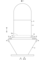
図1から図6を参照して、本実施形態に係るコーヒーグラインダースタンドの構成について説明する。図1は、本実施形態に係るコーヒーグラインダースタンド10を用いてコーヒーグラインダー本体16をコーヒードリッパ12の上側に載置した様子を示す模式図である。
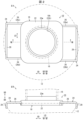
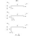
図2のIIAは、本実施形態に係るコーヒーグラインダースタンド10の模式的な平面図であり、図2のIIBは、本実施形態に係るコーヒーグラインダースタンド10の模式的な正面図である。図2のIIAとIIBは、一対のアーム部材24をコーヒーグラインダースタンド本体18より引き出した状態を示している。
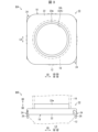
図3のIIIAは、本実施形態に係るコーヒーグラインダースタンド10の模式的な平面図であり、図3のIIIBは、本実施形態に係るコーヒーグラインダースタンド10の模式的な正面図である。図3のIIIAとIIIBは、一対のアーム部材24をコーヒーグラインダースタンド本体18から引き出す前の状態を示している。
The configuration of the coffee grinder stand according to this embodiment will be described with reference to FIGS. 1 to 6. FIG. 1 is a schematic diagram showing a state in which a coffee grinder
IIA in FIG. 2 is a schematic plan view of the coffee grinder stand 10 according to the present embodiment, and IIB in FIG. 2 is a schematic front view of the coffee grinder stand 10 according to the present embodiment. IIA and IIB in FIG. 2 show the pair of
IIIA in FIG. 3 is a schematic plan view of the coffee grinder stand 10 according to the present embodiment, and IIIB in FIG. 3 is a schematic front view of the coffee grinder stand 10 according to the present embodiment. IIIA and IIIB in FIG. 3 show the state before the pair of
図4のVIAは、本実施形態に係るコーヒーグラインダースタンド10からカバー部材22を取外した状態を示す模式的な平面図である。図4のIVBは、底面部20を示す模式的な平面図である。
VIA in FIG. 4 is a schematic plan view showing a state in which the
図4のVIAは、本実施形態に係るコーヒーグラインダースタンド10からカバー部材22を取外した状態で底面部20の上にアーム部材24を載せている状態を示す模式的な平面図である。図4のIVBは、アーム部材24がない底面部20を示す模式的な平面図である。
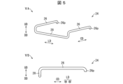
図5のVAは、アーム部材24を示す模式的な斜視図であり、図5のVBは、アーム部材24を示す模式的な側面図である。
図6のVIAからVICは、他の態様に係るアーム部材24を示す模式的な側面図である。
VIA in FIG. 4 is a schematic plan view showing a state in which the
VA in FIG. 5 is a schematic perspective view showing the
VIA to VIC in FIG. 6 are schematic side views showing an
(コーヒーグラインダースタンド10の概要)
図1に示すように、本発明の実施形態に係るコーヒーグラインダースタンド10は、コーヒーグラインダー14をコーヒードリッパ12の上側に載置するための器具であり(コーヒードリッパ12の上にコーヒーグラインダースタンド10を載置しさらにそのコーヒーグラインダースタンド10の上にコーヒーグラインダー14を載置する)、コーヒーミル台とも称される。ここで、コーヒーグラインダー14は、コーヒー豆を粉砕してコーヒー粉に挽くための装置である。コーヒーグラインダー14は、筒状のコーヒーグラインダー本体16と、コーヒーグラインダー本体16内に設けられかつコーヒー豆を粉砕する電動式又は手動式の粉砕機構(不図示)とを備えている。コーヒードリッパ12は、コーヒー粉を濾過してコーヒー液を抽出するための器具である。 コーヒードリッパ12の内側には、ペーパーフィルタ(不図示)が載置される。1~2杯用のコーヒードリッパ12の口径は、例えば90mm程度である。1~4杯用のコーヒードリッパ12の口径は、例えば116mm程度である。1~6杯用のコーヒードリッパ12の口径は、例えば134mm程度である。
(Summary of coffee grinder stand 10)
As shown in FIG. 1, the coffee grinder stand 10 according to the embodiment of the present invention is a device for placing the
(コーヒーグラインダースタンド本体18、貫通孔18h、底面部20)
図2のIIAとIIB、図3のIIIAとIIIB、及び図4のIVAとIVBに示すように、コーヒーグラインダースタンド10は、本体部としての箱状のコーヒーグラインダースタンド本体18を備えており、コーヒーグラインダースタンド本体18の平面視形状は、矩形状(例えば1辺85mm)になっている。コーヒーグラインダースタンド本体18は、その中央部に、コーヒーグラインダー14によって挽かれたコーヒー粉を通過させるための円形の貫通孔18h(貫通孔の直径は例えば54mm)を有している。コーヒーグラインダースタンド本体18は、矩形状の底面部20を有しており、底面部20は、合成樹脂により構成されている。底面部20は、その中央部に、円形の貫通孔20hを有している。なお、底面部20は、合成樹脂の代わりに、例えばアルミ合金等の金属により構成されてもよい。さらに、底面方向からみた底面部20(底面部下面)には、合成樹脂等で構成されている部分にさらにゴムなど防滑用材を施すことでコーヒードリッパ12の大きさに応じた滑り止めの効果を有する。
(Coffee grinder stand
As shown in IIA and IIB in FIG. 2, IIIA and IIIB in FIG. 3, and IVA and IVB in FIG. The grinder stand
(カバー部材22、壁部22w)
図2のIIAとIIB、及び図3のIIIAとIIIBに示すように、コーヒーグラインダースタンド本体18は、底面部20(図4参照)の上側に設けられた矩形状のカバー部材22を備えており、カバー部材22は、合成樹脂により構成されている。カバー部材22は、その中央部に、円形の貫通孔22hを有しており、貫通孔22hは、コーヒーグラインダースタンド本体18の貫通孔18hに相当する。なお、カバー部材22は、合成樹脂の代わりに、例えばアルミ合金等の金属により構成されてもよい。
(
As shown in IIA and IIB in FIG. 2 and IIIA and IIIB in FIG. 3, the coffee grinder stand
カバー部材22の貫通孔22hの周縁部には、コーヒーグラインダー本体16の下端部を保持する保持部として、起立した円環状の壁部22w(例えば8mm)が形成されている。壁部22wは、カバー部材22の上面から突出し、底面部20の貫通孔20hの内周面まで延びている。カバー部材22の壁部22wは、コーヒーグラインダー14をコーヒーグラインダー本体16に載置(設置)するための部位であり、コーヒーグラインダー本体16の下端部の内側(径方向内側)に位置する。カバー部材22の外縁部は、底面部20の外縁部に溶着されており、カバー部材22の壁部22wは、底面部20の貫通孔20hの内周面に溶着されている。これにより、水がコーヒーグラインダースタンド本体18の中に入らないようにでき、コーヒーグラインダースタンド本体18の密閉性が向上する。
An upright
(アーム部材24)
図2のIIAとIIB、及び図5のVAとVBに示すように、コーヒーグラインダー14は、コーヒーグラインダースタンド本体18の横方向の両側部に引き出し可能にそれぞれ設けられたアーム部材24(平行ロッド26と連結ロッド28からなる)を備えており、アーム部材24のうち連結ロッド28はコーヒードリッパ12の周縁部を下方向から係止する。各アーム部材24は、例えばステンレス合金等の耐腐食性の金属により構成されている。
(Arm member 24)
As shown in IIA and IIB in FIG. 2 and VA and VB in FIG. 5, the
図4のIVAと図5のVAとVBに示すように、アーム部材24は、例えば、1本のステンレス合金等(例えば、断面が略円形で直径3mm)を曲げ加工することで、図5平面視形状でU字形状に形成する。さらに、アーム部材24の先端部側(連結ロッド28となる部分)をさらに1回の曲げ加工によって図2の正面図で見て(横方向から見て)平行ロッドから下方向に向かって略90°曲げられている。
As shown in IVA in FIG. 4 and VA and VB in FIG. It is formed into a U-shape in visual form. Furthermore, the distal end side of the arm member 24 (the part that will become the connecting rod 28) is further bent once, so that the
各アーム部材24は、コーヒーグラインダースタンド本体18の横方向の側部に引き出し可能に設けられた一対の平行ロッド26を有しており、一対の平行ロッド26は、横方向に沿って平行に延びている。各一対の平行ロッド26は、コーヒーグラインダースタンド本体18の貫通孔18hの縦方向の両側に位置している。一方のアーム部材24における一対の平行ロッド26a,26bは、コーヒーグラインダースタンド本体18の貫通孔18hの横方向の一方側でかつ縦方向の両側に位置している。他方のアーム部材24における一対の平行ロッド26c,26dは、コーヒーグラインダースタンド本体18の貫通孔18hの横方向の他方側でかつ縦方向の両側に位置している。各平行ロッド26における、連結ロッド28と連結してない端部には、平行ロッド26に対し下方向(DD)に突出した突起26pが形成されている。
Each
各アーム部材24は、一対の平行ロッド26の先端部(例えば図2の平行ロッド26a,26bの右側の先端部、また、平行ロッド26c,26dの左側の先端部)同士の間に連結するように設けられた連結ロッド28を有しており、連結ロッド28は、平行ロッド26に対して下方向(DD)に突出している。図5のVAに示すように、各連結ロッド28の側面視形状(横方向から見た形状)は、U字形状である。
Each
各連結ロッド28は、コーヒーグラインダースタンド本体18の貫通孔18hの横方向の片側に位置している。一方のアーム部材24の連結ロッド28は、コーヒーグラインダースタンド本体18の貫通孔18hの横方向の一方側に位置している。他方のアーム部材24の連結ロッド28は、コーヒーグラインダースタンド本体18の貫通孔18hの横方向の他方側に位置している。
Each connecting
図5の各アーム部材24の先端部側(連結ロッド28側)が1回の曲げ加工によって正面図で見て下方向に略90°折曲げられる。図6のVIAは、1回目に略90°折り曲げ加工後、さらに、折り曲げ加工によって略90°折り曲げている。
The tip end side (connecting
さらに、図6のVICに示すように1回目の略90°折り曲げ加工後、さらに、2回目の折り曲げ加工は図6のVIAより折り曲げ角度を少なくし横方向に対して傾斜した傾斜部28sを形成してもよい。 Furthermore, as shown in VIC in FIG. 6, after the first approximately 90° bending process, the second bending process is performed with a smaller bending angle than VIA in FIG. You may.
さらに、図6のVIBに示すように、1回目、2回目の折り曲げ加工は略90°とし
3回目の折り曲げ加工は図6のVIAより折り曲げ角度を少なくし横方向に対して傾斜した傾斜部28sを形成してもよい。
Furthermore, as shown in VIB of FIG. 6, the first and second bending processes are approximately 90 degrees, and the third bending process is performed with a bending angle smaller than that of VIA in FIG. may be formed.
アーム部材24を複数の折り曲げることによりコーヒードリッパ12の側面も保持することができ、コーヒーグラインダー14とコーヒードリッパ12の保持力がさらに向上する。
By bending the arm member 24 a plurality of times, the sides of the
(コーヒーグラインダースタンド本体18とアーム部材24との関係)
図4のIVAとIVB、及び図5のVAに示すように、底面部20の上面における縦方向の両端側には、各平行ロッド26を横方向へ移動可能に案内するための一対のガイド溝20gがそれぞれ形成されており、各ガイド溝20gは、横方向に延びている。一方のアーム部材24を横方向へ移動可能に案内するための一対のガイド溝20gと、他方のアーム部材24を横方向へ移動可能に案内するための一対のガイド溝20gは、重ならないように縦方向(LD)にずらして配置されている。これにより、一対の平行ロッド26a,26bと一対の平行ロッド26c,26dが干渉することなく、一対の平行ロッド26a,26bと一対の平行ロッド26c,26dをコーヒーグラインダースタンド本体18に収納することができる。
(Relationship between coffee grinder stand
As shown in IVA and IVB in FIG. 4 and VA in FIG. 20g are formed, and each
底面部20の各ガイド溝20gの底面には、各平行ロッド26を下方向から支持する支持部20bが形成されている。底面部20の各ガイド溝20gの底面における支持部20bから横方向に離隔した位置には、各連結ロッド28の突起26pに当接可能なストッパ部20sが形成されており、各ストッパ部20sは、各平行ロッド26を下方向から支持する。各平行ロッド26の突起26pが底面部20の各ストッパ部20sに当接することで、コーヒーグラインダースタンド本体18に対する各アーム部材24の最大の引き出し量(例えば33mm)を規定すると共に、コーヒーグラインダースタンド本体18に対する各アーム部材24の離脱を防止することができる。
A
なお、各アーム部材24が一対の平行ロッド26と連結ロッド28とを備えているが、各アーム部材24がコーヒードリッパ12の周縁部に係止可能であれば、各アーム部材24の構成を適宜に変更してもよい。例えば、各アーム部材24を板状に形成し、各アーム部材24の先端部にコーヒードリッパ12の周縁部に係止可能なフック部を設けてもよい。
Note that each
(作用効果)
本実施形態に係るコーヒーグラインダースタンド10の構成によれば、図2のIIBに示すように、カバー部材22の壁部22wをコーヒーグラインダー本体16の下端部の内側に位置させることで、換言すれば、コーヒーグラインダー本体16の下端部を保持部としての壁部22wで保持させることで、コーヒーグラインダー14をコーヒーグラインダースタンド本体18に安定して載置することができる。また、一対のアーム部材24をコーヒードリッパ12の周縁部にそれぞれ係止させる。これにより、コーヒーグラインダースタンド本体18とコーヒードリッパ12を上下方向や左右方向に離隔させることなく、コーヒーグラインダー14をコーヒードリッパ12の上側に載置することができる。その結果、コーヒーグラインダー14によって挽かれたコーヒー粉が飛び散ることなく、コーヒードリッパ12に載置したペーパーフィルタ内にコーヒー粉を直接収容させることができる。
(effect)
According to the configuration of the coffee grinder stand 10 according to the present embodiment, as shown in IIB of FIG. By holding the lower end of the
一対のアーム部材24がコーヒーグラインダースタンド本体18の横方向の側部に対して引き出し可能になっている。そのため、一対のアーム部材24を引き出す前の状態
(図3のIIIA、IIIBの状態)では、連結ロッド28がコーヒーグラインダースタンド本体18よりも下に位置するため(図3のIIIB)、平面図視(図3のIIIA)でみると、連結ロッド28はコーヒーグラインダースタンド本体18の側面部とほぼ同じ場所に収まることができる。アーム部材24があったとしてもコーヒーグラインダースタンド18の横方向の寸法内に収めることができる。これにより、コーヒーグラインダースタンド10のコンパクト化を図りつつ、コーヒーグラインダースタンド10の収納性及び携帯性を高めることができる。
A pair of
つまり、本実施形態によれば、コーヒーグラインダースタンド10の収納性及び携帯性を高めつつ、コーヒーグラインダー14によって挽かれたコーヒー粉が飛び散ることなく、ペーパーフィルタ内にコーヒー粉を収容させることができる。
That is, according to the present embodiment, the coffee powder ground by the
また、コーヒーグラインダー14をコーヒードリッパ12の上側に載置できるため、電動式のコーヒーグラインダー14によってコーヒー豆を挽くときに、人がコーヒーグラインダー14を小さな力で保持することができる。そのため、本実施形態によれば、コーヒー豆を挽くための作業が楽になる。
Furthermore, since the
図2のIIAとIIBに示すように、コーヒードリッパ12の口径がコーヒーグラインダースタンド本体18の横方向及び縦方向の寸法よりも十分に大きい場合には、コーヒーグラインダースタンド10をコーヒードリッパ12に載置する際に、各アーム部材24をコーヒーグラインダースタンド本体18の横方向の側部から引き出すことで、コーヒーグラインダースタンド本体18の一部または全部をコーヒードリッパ12の内側に位置させることができる。そして、各連結ロッド28の中央部の上部と各一対の平行ロッド26における連結ロッド28に近い先端部の下部との協働によって、コーヒードリッパ12の周縁部を上下方向から例えば3点で挟持することができ、コーヒードリッパ12に対するコーヒーグラインダースタンド10の載置状態を安定させることができる。
As shown in IIA and IIB in FIG. 2, when the diameter of the
図3のIIIAとIIIBに示すように、コーヒードリッパ12の口径がコーヒーグラインダースタンド本体18の横方向及び縦方向の寸法と同程度である場合(各アーム部材24をコーヒーグラインダースタンド本体18の横方向の側部にほとんど引き出さない場合)には、コーヒーグラインダースタンド10をコーヒードリッパ12に載置する際に、コーヒーグラインダースタンド本体18をコーヒードリッパ12の周縁部に位置させることができる。換言すれば、各連結ロッド28とコーヒーグラインダースタンド本体18の底部との間に隙間(例えば5mm)があるため、この隙間にコーヒードリッパ12の周縁部が収まることができる。これにより、各連結ロッド28の中央部の上端部とコーヒーグラインダースタンド本体18の縦方向の両側部との協働によってコーヒードリッパ12の周縁部を上下方向から挟持することができ、コーヒードリッパ12に対するコーヒーグラインダースタンド10の載置状態を安定させることができる。
As shown in IIIA and IIIB in FIG. When the coffee grinder stand 10 is placed on the
つまり、本実施形態によれば、コーヒードリッパ12の口径が変わっても、コーヒーグラインダースタンド本体18からでるアーム部材24の長さを可変にすることで、コーヒードリッパ12に対するコーヒーグラインダースタンド10の載置状態を安定させることができ、コーヒーグラインダースタンド10の取扱性を高めることができる。
That is, according to the present embodiment, even if the diameter of the
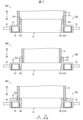
図7を参照して、本実施形態の変形例1から変形例3に係るコーヒーグラインダースタンド10A,10B,10Cについて説明する。図7は、図2のIIAのVII-VII線に沿った断面図に相当する図である。図7のVIIAは、本発明の実施形態の変形例1に係るコーヒーグラインダースタンド10Aの一部を示す模式的な縦断面図である。図7のVIIBは、本発明の実施形態の変形例2に係るコーヒーグラインダースタンド10Bの一部を示す模式的な縦断面図である。図7のVIICは、本発明の実施形態の変形例3に係るコーヒーグラインダースタンド10Cの一部を示す模式的な縦断面図である。
With reference to FIG. 7, coffee grinder stands 10A, 10B, and 10C according to modified examples 1 to 3 of the present embodiment will be described. FIG. 7 is a diagram corresponding to a cross-sectional view taken along line VII-VII of IIA in FIG. VIIA in FIG. 7 is a schematic vertical sectional view showing a part of the coffee grinder stand 10A according to
(変形例1)
図7のVIIAに示すように、本実施形態の変形例1に係るコーヒーグラインダースタンド10Aにおいて、カバー部材22の壁部22wの外周面には、コーヒーグラインダー本体16の内周面に形成した雌ねじ部16fに螺合する雄ねじ部22mが形成されている。
(Modification 1)
As shown in VIIA of FIG. 7, in the coffee grinder stand 10A according to the first modification of the present embodiment, the outer circumferential surface of the
本実施形態の変形例1に係るコーヒーグラインダースタンド10Aの構成によれば、コーヒーグラインダー本体16をカバー部材22の壁部22wにねじ込みながら保持させることで、コーヒーグラインダー本体16に対するコーヒーグラインダー14の載置状態をより安定させることができる。従って、本実施形態の変形例1によれば、コーヒーグラインダースタンド10Aの取扱性をより高めることができる。
According to the configuration of the coffee grinder stand 10A according to the first modification of the present embodiment, the
(変形例2)
図7のVIIBに示すように、本実施形態の変形例2に係るコーヒーグラインダースタンド10Bにおいて、起立した円環状の壁部22wは、コーヒーグラインダー本体16の外側(径方向外側)に位置する。カバー部材22の壁部22wの内周面には、コーヒーグラインダー本体16の外周面に形成した雄ねじ部16mに螺合する雌ねじ部22fが形成されている。
(Modification 2)
As shown in VIIB of FIG. 7, in the coffee grinder stand 10B according to the second modification of the present embodiment, the upright
本実施形態の変形例2に係るコーヒーグラインダースタンド10Bの構成によれば、コーヒーグラインダー本体16をカバー部材22の壁部22wにねじ込みながら保持させることで、コーヒーグラインダー本体16に対するコーヒーグラインダー14の載置状態をより安定させることができる。従って、本実施形態の変形例2によれば、コーヒーグラインダースタンド10Bの取扱性をより高めることができる。
According to the configuration of the coffee grinder stand 10B according to the second modification of the present embodiment, the
(変形例3)
図7のVIICに示すように、本実施形態の変形例3に係るコーヒーグラインダースタンド10Cにおいて、カバー部材22の貫通孔22hの周縁部には、コーヒーグラインダー本体16の下端部を保持する保持部として、環状の溝部22g(溝部22gの幅5mm以上)が形成されている。カバー部材22の溝部22gの外縁部に、コーヒーグラインダー本体16の外側に位置する環状又は円弧状の壁部を形成してもよい。カバー部材22の溝部22gの内縁部に、コーヒーグラインダー本体16の内側に位置する環状又は円弧状の壁部を形成してもよい。
(Modification 3)
As shown in VIIC of FIG. 7, in the coffee grinder stand 10C according to the third modification of the present embodiment, a holding portion for holding the lower end of the coffee grinder
本実施形態の変形例3に係るコーヒーグラインダースタンド10Cの構成によれば、コーヒーグラインダー本体16の下端部をカバー部材22の溝部22gで保持させることで、コーヒーグラインダー14をコーヒーグラインダースタンド10Cに載置することができる。これにより、本実施形態の変形例3によれば、コーヒーグラインダースタンド10Cの取扱性を高めることができる。更に、種類の異なるコーヒーグラインダー14であっても、コーヒーグラインダー本体16の下端部をカバー部材22の溝部22gに嵌めることができれば、コーヒーグラインダー14をコーヒーグラインダースタンド10Cに載置することができる。
According to the configuration of the coffee grinder stand 10C according to the third modification of the present embodiment, the
〔まとめ〕
本発明の態様1に係るコーヒーグラインダースタンドは、コーヒーグラインダをコーヒードリッパの上側に載置するためのコーヒーグラインダースタンドであって、本体部と、前記本体部には前記コーヒーグラインダによって挽かれたコーヒ粉を通過させる貫通孔と、前記貫通孔の周縁部にある前記コーヒーグラインダを保持する保持部と、前記本体部の横方向の両側部に引き出し可能にそれぞれ設けられた前記コーヒードリッパの側面を保持するためのアーム部材と、を備える。
〔summary〕
A coffee grinder stand according to
前記の構成によれば、前記コーヒーグラインダーのコーヒーグラインダー本体の下端部を前記保持部で保持させることで、前記コーヒーグラインダーを前記本体部に安定して載置することができる。これにより、前記本体部と前記コーヒードリッパを上下方向や左右方向に離隔させることなく、前記コーヒーグラインダーを前記コーヒードリッパの上側に載置することができる。その結果、前記コーヒーグラインダーによって挽かれたコーヒー粉が飛び散ることなく、前記コーヒードリッパに載置したペーパーフィルタ内にコーヒー粉を収容させることができる。 According to the above configuration, by holding the lower end portion of the coffee grinder main body of the coffee grinder with the holding portion, the coffee grinder can be stably placed on the main body portion. Thereby, the coffee grinder can be placed above the coffee dripper without vertically or horizontally separating the main body and the coffee dripper. As a result, the coffee powder ground by the coffee grinder can be accommodated in the paper filter placed on the coffee dripper without scattering.
前記一対のアーム部材が前記本体部の横方向の側部に対して引き出し可能になっている。そのため、前記一対のアーム部材を引き出す前における、前記コーヒーグラインダースタンドの横方向の寸法を短くすることができる。これにより、前記コーヒーグラインダースタンドのコンパクト化を図りつつ、前記コーヒーグラインダースタンドの収納性及び携帯性を高めることができる。 The pair of arm members can be pulled out from the lateral sides of the main body. Therefore, the lateral dimension of the coffee grinder stand before the pair of arm members is pulled out can be shortened. Thereby, it is possible to make the coffee grinder stand more compact and to improve the storability and portability of the coffee grinder stand.
本発明の態様2に係るコーヒーグラインダースタンドは、前記態様1において、前記保持部は起立した壁部であってもよい。 In the coffee grinder stand according to a second aspect of the present invention, in the first aspect, the holding portion may be an upright wall portion.
前記の構成によれば、前記壁部に前記コーヒーグラインダーのコーヒーグラインダー本体の下端部の内側又は外側に位置させることで、前記コーヒーグラインダーを前記本体部に安定して載置することができる。 According to the above configuration, the coffee grinder can be stably mounted on the main body by locating the wall on the inside or outside of the lower end of the coffee grinder main body of the coffee grinder.
本発明の態様3に係るコーヒーグラインダースタンドは、前記態様1又は2において、各アーム部材は、横方向に沿って平行に延びた一対の平行ロッドと、前記一対の平行ロッドの先端部同士の間に連結するように設けられ、前記平行ロッドに対して下方向に突出した連結ロッドと、を有してもよい。言い換えるなら、一対の平行ロッドにおける本体部からでた端部同士の間に連結ロッドが連結するようにする。
In the coffee grinder stand according to aspect 3 of the present invention, in the
前記の構成により、前記一対のアーム部材を引き出す前の状態では、前記連結ロッドが前記本体部よりも下に位置するため、平面図視でみると、前記連結ロッドは前記本板部の側面部とほぼ同じ場所に収まることができる。前記一対のアーム部材があったとしても前記本体部の横方向の寸法内に収めることができる。これにより、前記コーヒーグラインダースタンドのコンパクト化をより図りつつ、前記コーヒーグラインダースタンドの収納性及び携帯性をより高めることができる。 With the above configuration, before the pair of arm members are pulled out, the connecting rod is located below the main body, so when viewed from a plan view, the connecting rod is located on the side surface of the main plate. can fit in almost the same place. Even if the pair of arm members are present, they can be accommodated within the lateral dimension of the main body. Thereby, the coffee grinder stand can be made more compact, and the storability and portability of the coffee grinder stand can be further improved.
また、前記コーヒードリッパの口径が前記本体部コーヒーグラインダースタンド本体の横方向及び縦方向の寸法よりも十分に大きい場合には、前記コーヒーグラインダースタンドを前記コーヒードリッパに載置する際に、前記コーヒーグラインダースタンド本体の一部を前記コーヒードリッパの中央側に位置させることができる。そして、各連結ロッドの中央部の上部と各一対の平行ロッドにおける連結ロッド28に近い先端部の下部との協働によって、前記コーヒードリッパの周縁部を上下方向から例えば3点で挟持することができ、前記コーヒードリッパに対する前記コーヒーグラインダースタンドの載置状態を安定さることができる。
Further, when the diameter of the coffee dripper is sufficiently larger than the horizontal and vertical dimensions of the coffee grinder stand main body, when the coffee grinder stand is placed on the coffee dripper, the coffee grinder A part of the stand main body can be located at the center of the coffee dripper. By cooperation between the upper part of the center of each connecting rod and the lower part of the tip of each pair of parallel rods close to the connecting
前記コーヒードリッパの口径が前記コーヒーグラインダースタンド本体の横方向及び縦方向の寸法と同程度である場合には、前記コーヒーグラインダースタンドを前記コーヒードリッパに載置する際に、前記コーヒーグラインダースタンド本体を前記コーヒードリッパの周縁部に位置させることができる。換言すれば、各連結ロッドと前記本体部の底部との間に隙間(例えば5mm)があるため、この隙間に前記コーヒードリッパ12の周縁部が収まることができる。これにより、各連結ロッドの中央部の上端部と前記コーヒーグラインダースタンド本体の縦方向の両側部との協働によって前記コーヒードリッパの周縁部を上下方向から挟持することができ、前記コーヒードリッパに対する前記コーヒーグラインダースタンドの載置状態を安定させることができる。
If the diameter of the coffee dripper is approximately the same as the horizontal and vertical dimensions of the coffee grinder stand main body, when the coffee grinder stand is placed on the coffee dripper, the coffee grinder stand main body is It can be located at the periphery of the coffee dripper. In other words, since there is a gap (for example, 5 mm) between each connecting rod and the bottom of the main body, the peripheral edge of the
つまり、前記コーヒードリッパの口径が変わっても、前記本体部からでる前記アーム部材の長さを可変にすることで、前記コーヒードリッパに対する前記コーヒーグラインダースタンドの載置状態を安定させることができ、前記コーヒーグラインダースタンドの取扱性を高めることができる。 That is, even if the diameter of the coffee dripper changes, by making the length of the arm member coming out from the main body variable, the state in which the coffee grinder stand is placed on the coffee dripper can be stabilized, and the The handleability of the coffee grinder stand can be improved.
発明の態様4に係るコーヒーグラインダースタンドは、前記態様2から3のいずれか
において、前記壁部は、コーヒーグラインダーにおけるコーヒーグラインダー本体の下端
部の内側に位置してもよい。
In the coffee grinder stand according to aspect 4 of the invention, in any one of
前記の構成によれば、前記コーヒーグラインダーを前記本体部に載置するときに、前記壁部が前記コーヒーグラインダーのコーヒーグラインダー本体の下端部の内側に位置する。 According to the above configuration, when the coffee grinder is placed on the main body part, the wall part is located inside the lower end part of the coffee grinder main body of the coffee grinder.
前記の構成によれば、前記壁部を前記コーヒーグラインダーのコーヒーグラインダー本体の下端部の内側に位置させることで、前記コーヒーグラインダーを前記本体部に載置することができる。 According to the above configuration, the coffee grinder can be placed on the main body by locating the wall inside the lower end of the coffee grinder main body of the coffee grinder.
本発明の態様5に係るコーヒーグラインダースタンドは、前記態様4において、前記壁 部の外周面に、前記コーヒーグラインダー本体の内周面に形成した雌ねじ部に螺合する雄 ねじ部が形成されてもよい。 In the coffee grinder stand according to Aspect 5 of the present invention, in Aspect 4 , a male threaded portion may be formed on the outer circumferential surface of the wall portion to be screwed into a female threaded portion formed on the inner circumferential surface of the coffee grinder main body. good.
前記の構成によれば、前記コーヒーグラインダー本体を前記壁部にねじ込むことで、前
記コーヒーグラインダースタンド本体に対する前記コーヒーグラインダーの載置状態を安
定させることができる。
本発明の態様6に係るコーヒーグラインダースタンドは、前記態様1において、前記保
持部は環状の溝部であってもよい。
According to the above configuration, by screwing the coffee grinder main body into the wall portion, the mounting state of the coffee grinder on the coffee grinder stand main body can be stabilized.
In the coffee grinder stand according to aspect 6 of the present invention, in
前記の構成によれば、前記コーヒーグラインダーのコーヒーグラインダー本体の下端部を前記溝部に保持させることで、前記コーヒーグラインダーを前記本体部に載置することができる。 According to the above configuration, the coffee grinder can be placed on the main body by holding the lower end of the coffee grinder main body of the coffee grinder in the groove.
〔付記事項〕
本発明は前述した実施形態の説明に限定されるものではなく、請求項に示した範囲で種々の変更が可能であり、実施形態にそれぞれ開示された技術的手段を適宜組み合わせて得られる実施形態についても本発明の技術的範囲に含まれる。
[Additional notes]
The present invention is not limited to the description of the embodiments described above, and various changes can be made within the scope of the claims, and embodiments obtained by appropriately combining technical means disclosed in the embodiments. are also included within the technical scope of the present invention.
10 コーヒーグラインダースタンド
12 コーヒードリッパ
14 コーヒーグラインダー
16 コーヒーグラインダー本体
18 コーヒーグラインダースタンド本体(本体部)
18h 貫通孔
20 底面部
20h 貫通孔
20b 支持部
20g ガイド溝
20s ストッパ部
22 カバー部材
22w 壁部(保持部)
24 アーム部材
26 平行ロッド
26p 突起
28 連結ロッド
28s 傾斜部
10A 変形例1に係るコーヒーグラインダースタンド
16f 雌ねじ部
22m 雄ねじ部
10B 変形例2に係るコーヒーグラインダースタンド
16m 雄ねじ部
22f 雌ねじ部
10C 変形例3に係るコーヒーグラインダースタンド
22g 溝部(保持部)
10 Coffee grinder stand 12
18h Through
24
Claims (6)
本体部と、
前記本体部には前記コーヒーグラインダによって挽かれたコーヒ粉を通過させる貫通孔と、
前記貫通孔の周縁部にある前記コーヒーグラインダを保持する保持部と、
前記本体部の横方向の両側部に引き出し可能にそれぞれ設けられた前記コーヒードリッパの側面を保持するためのアーム部材と、を備える、コーヒーグラインダースタンド。 A coffee grinder stand for placing a coffee grinder above a coffee dripper,
The main body and
The main body includes a through hole through which coffee powder ground by the coffee grinder passes ;
a holding part that holds the coffee grinder at a peripheral edge of the through hole;
A coffee grinder stand, comprising: arm members for holding the sides of the coffee dripper that are removably provided on both sides of the main body in the lateral direction.
横方向に沿って平行に延びた一対の平行ロッドと、
前記一対の平行ロッドの先端部同士の間に連結するように設けられ、前記平行ロッドに
対して下方向に突出した連結ロッドと、を有する、請求項1に記載のコーヒーグラインダースタンド。 Each arm member is
a pair of parallel rods extending in parallel along the lateral direction;
The coffee grinder stand according to claim 1, further comprising a connecting rod that is connected between the tip ends of the pair of parallel rods and projects downward with respect to the parallel rods.
合する雄ねじ部が形成されている、請求項4に記載のコーヒーグラインダースタンド。 5. The coffee grinder stand according to claim 4 , wherein a male threaded portion is formed on the outer peripheral surface of the wall portion to be threaded into a female threaded portion formed on the inner peripheral surface of the coffee grinder main body.
Priority Applications (1)
| Application Number | Priority Date | Filing Date | Title |
|---|---|---|---|
| JP2023092636A JP7361237B1 (en) | 2023-06-05 | 2023-06-05 | coffee grinder stand |
Applications Claiming Priority (1)
| Application Number | Priority Date | Filing Date | Title |
|---|---|---|---|
| JP2023092636A JP7361237B1 (en) | 2023-06-05 | 2023-06-05 | coffee grinder stand |
Publications (2)
| Publication Number | Publication Date |
|---|---|
| JP7361237B1 true JP7361237B1 (en) | 2023-10-13 |
| JP2024174678A JP2024174678A (en) | 2024-12-17 |
Family
ID=88242124
Family Applications (1)
| Application Number | Title | Priority Date | Filing Date |
|---|---|---|---|
| JP2023092636A Active JP7361237B1 (en) | 2023-06-05 | 2023-06-05 | coffee grinder stand |
Country Status (1)
| Country | Link |
|---|---|
| JP (1) | JP7361237B1 (en) |
Citations (7)
| Publication number | Priority date | Publication date | Assignee | Title |
|---|---|---|---|---|
| DE202011002689U1 (en) | 2011-02-12 | 2011-06-09 | Vogt, Winold, 91541 | Coffee grinder with filter |
| JP2014530684A (en) | 2011-09-30 | 2014-11-20 | スターバックス・コーポレイション | Apparatus, system and method for grinding materials |
| JP3214079U (en) | 2017-09-15 | 2017-12-21 | 劉清海 | Portable coffee mill and coffee extraction device |
| US20200054162A1 (en) | 2018-08-14 | 2020-02-20 | Misaine Trade, Inc. | Modular coffee grinder system |
| JP2022085580A (en) | 2020-11-27 | 2022-06-08 | 大二郎 今永 | Mill and its support tool |
| JP3238359U (en) | 2022-05-10 | 2022-07-19 | 喬 竹岡 | Coffee mill stand |
| CN217959816U (en) | 2022-07-22 | 2022-12-06 | 好璃奥(上海)商贸有限公司 | Hand-operated bean grinder |
Family Cites Families (4)
| Publication number | Priority date | Publication date | Assignee | Title |
|---|---|---|---|---|
| JPS50155385U (en) * | 1974-06-10 | 1975-12-23 | ||
| JPS5326362A (en) * | 1976-08-20 | 1978-03-11 | Hitachi Chemical Co Ltd | Coffee mill |
| JPH0128742Y2 (en) * | 1987-05-14 | 1989-09-01 | ||
| KR200493831Y1 (en) * | 2019-01-24 | 2021-06-10 | 김정규 | Hand mill with dripper |
-
2023
- 2023-06-05 JP JP2023092636A patent/JP7361237B1/en active Active
Patent Citations (7)
| Publication number | Priority date | Publication date | Assignee | Title |
|---|---|---|---|---|
| DE202011002689U1 (en) | 2011-02-12 | 2011-06-09 | Vogt, Winold, 91541 | Coffee grinder with filter |
| JP2014530684A (en) | 2011-09-30 | 2014-11-20 | スターバックス・コーポレイション | Apparatus, system and method for grinding materials |
| JP3214079U (en) | 2017-09-15 | 2017-12-21 | 劉清海 | Portable coffee mill and coffee extraction device |
| US20200054162A1 (en) | 2018-08-14 | 2020-02-20 | Misaine Trade, Inc. | Modular coffee grinder system |
| JP2022085580A (en) | 2020-11-27 | 2022-06-08 | 大二郎 今永 | Mill and its support tool |
| JP3238359U (en) | 2022-05-10 | 2022-07-19 | 喬 竹岡 | Coffee mill stand |
| CN217959816U (en) | 2022-07-22 | 2022-12-06 | 好璃奥(上海)商贸有限公司 | Hand-operated bean grinder |
Also Published As
| Publication number | Publication date |
|---|---|
| JP2024174678A (en) | 2024-12-17 |
Similar Documents
| Publication | Publication Date | Title |
|---|---|---|
| RU2583252C2 (en) | Wheel assembly | |
| JP7361237B1 (en) | coffee grinder stand | |
| US6527126B2 (en) | Coffee filter restraint and flavor system | |
| CN107348866B (en) | grinder | |
| US9301650B1 (en) | Rotatable coffee pod storage device | |
| CN208807149U (en) | One kind being based on floral arrangement flower stand | |
| CN209215353U (en) | Drug dissolution apparatus for pharmaceutical experiment | |
| US20240065469A1 (en) | Beverage Infusion System with Removable Infusion Bed | |
| TW201424643A (en) | Cup lid structure easy to dismantle and clean | |
| JP3238359U (en) | Coffee mill stand | |
| JP2020089699A (en) | Filter attachable holder | |
| CN209214653U (en) | A kind of Magnetic gauge stand | |
| JP2018134158A (en) | Drip unit and drip tool | |
| CN222693237U (en) | Bean grinder bracket assembly | |
| CN220713670U (en) | 360-degree rotating coffee tamper holder and coffee tamper can be easily stored | |
| CN217145528U (en) | Inserted bar for truckle | |
| CN214796466U (en) | An invoice display model device for accounting profession | |
| CN210641561U (en) | Flower box with easy dismouting function | |
| CN206840047U (en) | A kind of hardware & tools rack | |
| CN209315452U (en) | A kind of anti-dropout coffee cup | |
| CN210110265U (en) | Adjustable poster support | |
| CN211559574U (en) | Tea placing table | |
| CN218355739U (en) | A hand brewing coffee stand | |
| CN219127435U (en) | Automatic decocting processing structure for Chinese herbal medicine materials | |
| KR20160001277A (en) | whetstone support device |
Legal Events
| Date | Code | Title | Description |
|---|---|---|---|
| A871 | Explanation of circumstances concerning accelerated examination |
Free format text: JAPANESE INTERMEDIATE CODE: A871 Effective date: 20230621 |
|
| A621 | Written request for application examination |
Free format text: JAPANESE INTERMEDIATE CODE: A621 Effective date: 20230621 |
|
| A131 | Notification of reasons for refusal |
Free format text: JAPANESE INTERMEDIATE CODE: A131 Effective date: 20230801 |
|
| A521 | Request for written amendment filed |
Free format text: JAPANESE INTERMEDIATE CODE: A523 Effective date: 20230906 |
|
| TRDD | Decision of grant or rejection written | ||
| A01 | Written decision to grant a patent or to grant a registration (utility model) |
Free format text: JAPANESE INTERMEDIATE CODE: A01 Effective date: 20230926 |
|
| A61 | First payment of annual fees (during grant procedure) |
Free format text: JAPANESE INTERMEDIATE CODE: A61 Effective date: 20231002 |
|
| R150 | Certificate of patent or registration of utility model |
Ref document number: 7361237 Country of ref document: JP Free format text: JAPANESE INTERMEDIATE CODE: R150 |