JP7366366B2 - electrostatic precipitator - Google Patents

electrostatic precipitator Download PDF

Info

Publication number
JP7366366B2
JP7366366B2 JP2019233439A JP2019233439A JP7366366B2 JP 7366366 B2 JP7366366 B2 JP 7366366B2 JP 2019233439 A JP2019233439 A JP 2019233439A JP 2019233439 A JP2019233439 A JP 2019233439A JP 7366366 B2 JP7366366 B2 JP 7366366B2
Authority
JP
Japan
Prior art keywords
electrode
outer electrode
inner electrode
electrostatic precipitator
heat storage
Prior art date
Legal status (The legal status is an assumption and is not a legal conclusion. Google has not performed a legal analysis and makes no representation as to the accuracy of the status listed.)
Active
Application number
JP2019233439A
Other languages
Japanese (ja)
Other versions
JP2021102181A (en
Inventor
貴誌 乾
章朝 瑞慶覧
将吾 井上
大貴 石塚
Current Assignee (The listed assignees may be inaccurate. Google has not performed a legal analysis and makes no representation or warranty as to the accuracy of the list.)
Fuji Electric Co Ltd
Ikutoku Gakuen School Corp
Original Assignee
Fuji Electric Co Ltd
Ikutoku Gakuen School Corp
Priority date (The priority date is an assumption and is not a legal conclusion. Google has not performed a legal analysis and makes no representation as to the accuracy of the date listed.)
Filing date
Publication date
Application filed by Fuji Electric Co Ltd, Ikutoku Gakuen School Corp filed Critical Fuji Electric Co Ltd
Priority to JP2019233439A priority Critical patent/JP7366366B2/en
Publication of JP2021102181A publication Critical patent/JP2021102181A/en
Application granted granted Critical
Publication of JP7366366B2 publication Critical patent/JP7366366B2/en
Active legal-status Critical Current
Anticipated expiration legal-status Critical

Links

Images

Landscapes

  • Electrostatic Separation (AREA)

Description

本発明は、電気集塵装置に関する。 The present invention relates to an electrostatic precipitator.

従来、電極端部に丸みを設けることにより、電極端部でのコロナ放電を抑制する電気集塵装置が知られている(例えば、特許文献1参照)。
特許文献1 特許第6274357号
Conventionally, an electrostatic precipitator is known that suppresses corona discharge at the electrode end by rounding the electrode end (see, for example, Patent Document 1).
Patent Document 1 Patent No. 6274357

電気集塵装置においては、消費電力を低減することが好ましい。 In an electrostatic precipitator, it is preferable to reduce power consumption.

本発明の第1の態様においては、電気集塵装置を提供する。電気集塵装置は、予め定められた延伸方向に延伸する内側電極と、内側電極の周囲に設けられ、内側電極の側面と対向する内側面を有する外側電極と、を備える。内側電極は、内側電極の上面と側面とを接続し、内側電極の下面と側面とを接続する第1端部を有する。外側電極は、外側電極の上面と内側面とを接続し、外側電極の下面と内側面とを接続する第2端部を有する。第1端部および第2端部の少なくとも一方には、丸みが設けられている。丸みの曲率半径は、側面と内側面との距離の1/2以上である。 In a first aspect of the invention, an electrostatic precipitator is provided. The electrostatic precipitator includes an inner electrode that extends in a predetermined stretching direction, and an outer electrode that is provided around the inner electrode and has an inner surface that faces the side surface of the inner electrode. The inner electrode has a first end that connects the upper surface and side surface of the inner electrode and connects the lower surface and side surface of the inner electrode. The outer electrode has a second end that connects the upper surface of the outer electrode and the inner surface, and connects the lower surface of the outer electrode and the inner surface. At least one of the first end and the second end is rounded. The radius of curvature of the roundness is 1/2 or more of the distance between the side surface and the inner surface.

延伸方向において、内側電極は外側電極よりも長くてよい。第2端部には、丸みが設けられていてよい。 In the stretching direction, the inner electrode may be longer than the outer electrode. The second end may be rounded.

延伸方向において、外側電極は内側電極よりも長くてよい。第1端部には、丸みが設けられていてよい。 In the stretching direction, the outer electrode may be longer than the inner electrode. The first end may be rounded.

電気集塵装置は、第1端部の少なくとも一方に接続される電極支持棒をさらに備えてよい。電極支持棒の側面と内側面との距離は、15mm以上であってよい。延伸方向に直交する直交方向における内側電極の幅は、直交方向における電極支持棒の幅よりも19mm以上大きくてよい。 The electrostatic precipitator may further include an electrode support rod connected to at least one of the first ends. The distance between the side surface and the inner surface of the electrode support rod may be 15 mm or more. The width of the inner electrode in the orthogonal direction perpendicular to the stretching direction may be 19 mm or more larger than the width of the electrode support rod in the orthogonal direction.

電気集塵装置は、外側電極の外側面の少なくとも一部に設けられた第1蓄熱材料をさらに備えてよい。第1蓄熱材料の単位体積当たりの熱容量は、外側電極の単位体積当たりの熱容量よりも大きくてよい。第1蓄熱材料の表面の熱伝導率は、外側電極の外側面の熱伝導率よりも小さくてよい。 The electrostatic precipitator may further include a first heat storage material provided on at least a portion of the outer surface of the outer electrode. The heat capacity per unit volume of the first heat storage material may be larger than the heat capacity per unit volume of the outer electrode. The thermal conductivity of the surface of the first heat storage material may be lower than the thermal conductivity of the outer surface of the outer electrode.

第1蓄熱材料が設けられた、外側電極の外側面の面積は、外側電極の外側面の面積の1/2以上であってよい。 The area of the outer surface of the outer electrode on which the first heat storage material is provided may be 1/2 or more of the area of the outer surface of the outer electrode.

電気集塵装置は、内側電極の内部の少なくとも一部に設けられた第2蓄熱材料をさらに備えてよい。第2蓄熱材料の単位体積当たりの熱容量は、内側電極の単位体積当たりの熱容量よりも小さくてよい。 The electrostatic precipitator may further include a second heat storage material provided inside at least a portion of the inner electrode. The heat capacity per unit volume of the second heat storage material may be smaller than the heat capacity per unit volume of the inner electrode.

第1蓄熱材料および第2蓄熱材料は、外側電極の温度が内側電極の温度よりも高くなるように、外側電極の温度と内側電極の温度とを保持してよい。 The first heat storage material and the second heat storage material may maintain the temperature of the outer electrode and the temperature of the inner electrode such that the temperature of the outer electrode is higher than the temperature of the inner electrode.

電気集塵装置は、外側電極の温度と内側電極の温度との少なくとも一方を測定する温度測定部と、をさらに備えてよい。内側電極および外側電極の一方に電源が接続されてよく、他方が接地されてよい。電源は、温度測定部により測定された、外側電極の温度および内側電極の温度の少なくとも一方に基づいて、内側電極と外側電極との間の電圧を制御してよい。 The electrostatic precipitator may further include a temperature measurement unit that measures at least one of the temperature of the outer electrode and the temperature of the inner electrode. A power source may be connected to one of the inner electrode and the outer electrode, and the other may be grounded. The power source may control the voltage between the inner electrode and the outer electrode based on at least one of the temperature of the outer electrode and the temperature of the inner electrode measured by the temperature measuring section.

なお、上記の発明の概要は、本発明の必要な特徴の全てを列挙したものではない。また、これらの特徴群のサブコンビネーションもまた、発明となりうる。 Note that the above summary of the invention does not list all the necessary features of the invention. Furthermore, subcombinations of these features may also constitute inventions.

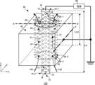
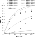
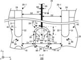
本発明の一つの実施形態に係る電気集塵装置100の載置の一例を示す図である。It is a figure showing an example of placement of electrostatic precipitator 100 concerning one embodiment of the present invention. 本発明の一つの実施形態に係る電気集塵装置100の一例を示す斜視図である。1 is a perspective view showing an example of an electrostatic precipitator 100 according to an embodiment of the present invention. 図2におけるA-A'線を通るXY断面の一例を示す図である。3 is a diagram showing an example of an XY cross section taken along line AA' in FIG. 2. FIG. 図2におけるB-B'線を通るXZ断面の一例を示す図である。3 is a diagram showing an example of an XZ cross section taken along line BB' in FIG. 2. FIG. 図2におけるB-B'線を通るXZ断面の一例を示す図である。3 is a diagram showing an example of an XZ cross section taken along line BB' in FIG. 2. FIG. 本発明の一つの実施形態に係る電気集塵装置100の集塵性能を検証するための集塵実験装置300の一例を示す図である。It is a diagram showing an example of a dust collection experimental device 300 for verifying the dust collection performance of the electrostatic precipitator 100 according to one embodiment of the present invention. 集塵実験装置300の電圧電流特性の測定結果を示す図である。3 is a diagram showing measurement results of voltage-current characteristics of the dust collection experimental device 300. FIG. 第1電極332および第2電極334の電極長Lが150mmの場合における集塵率[%]の電圧V依存性を、ガス302の流速Vgが0.5[m/s]~5.0[m/s]の場合について示す図である。The dependence of the dust collection rate [%] on the voltage V when the electrode length L of the first electrode 332 and the second electrode 334 is 150 mm is expressed as follows: The flow velocity Vg of the gas 302 is 0.5 [m/s] to 5.0 [m/s] FIG. ガス302の流速Vgが2.5m/sの場合における集塵率[%]の電圧V依存性を、電極長Lが50mm~450mmの場合について示す図である。FIG. 7 is a diagram showing the dependence of the dust collection rate [%] on voltage V when the flow velocity Vg of gas 302 is 2.5 m/s, and when the electrode length L is 50 mm to 450 mm. ガス302の流速Vgが1.5m/sの場合における集塵率[%]の電圧V依存性を、電極長Lが150mm~750mmの場合について示す図である。FIG. 7 is a diagram showing the dependence of the dust collection rate [%] on voltage V when the flow velocity Vg of gas 302 is 1.5 m/s, and when the electrode length L is 150 mm to 750 mm. 本発明の一つの実施形態に係る電気集塵装置100の他の一例を示す斜視図である。It is a perspective view showing another example of electrostatic precipitator 100 concerning one embodiment of the present invention. 図11におけるC-C'線を通るXZ断面の一例を示す図である。12 is a diagram showing an example of an XZ cross section taken along line CC' in FIG. 11. FIG. 本発明の一つの実施形態に係る電気集塵装置100の他の一例を示す図である。It is a figure showing another example of electrostatic precipitator 100 concerning one embodiment of the present invention. 本発明の一つの実施形態に係る電気集塵装置100の他の一例を示す図である。It is a figure showing another example of electrostatic precipitator 100 concerning one embodiment of the present invention. 本発明の一つの実施形態に係る電気集塵装置100の他の一例を示す図である。It is a figure showing another example of electrostatic precipitator 100 concerning one embodiment of the present invention.

以下、発明の実施の形態を通じて本発明を説明するが、以下の実施形態は特許請求の範囲にかかる発明を限定するものではない。また、実施形態の中で説明されている特徴の組み合わせの全てが発明の解決手段に必須であるとは限らない。 Hereinafter, the present invention will be described through embodiments of the invention, but the following embodiments do not limit the invention according to the claims. Furthermore, not all combinations of features described in the embodiments are essential to the solution of the invention.

図1は、本発明の一つの実施形態に係る電気集塵装置(ESP:Electrostatic Precipitator)100の載置の一例を示す図である。本例において、電気集塵装置100は工場200に載置されている。工場200には、動力装置110が設けられている。動力装置110は、例えば、工場200に設けられた空調設備等の電力設備を稼働させる発動機である。動力装置110は、燃料の燃焼による排ガス120を発生する。動力装置110は、例えば船舶等に搭載されるエンジンであってもよい。電気集塵装置100は、例えば船舶等に載置されてもよい。 FIG. 1 is a diagram showing an example of placement of an electrostatic precipitator (ESP) 100 according to one embodiment of the present invention. In this example, the electrostatic precipitator 100 is installed in a factory 200. The factory 200 is provided with a power plant 110. The power plant 110 is, for example, a motor that operates power equipment such as air conditioning equipment provided in the factory 200. The power plant 110 generates exhaust gas 120 by burning fuel. The power plant 110 may be, for example, an engine mounted on a ship or the like. The electrostatic precipitator 100 may be installed, for example, on a ship or the like.

排ガス120には、窒素酸化物(NOx)、硫黄酸化物(SOx)および粒子状物質(PM:Particle Matter)等の物質が含まれる。粒子状物質(PM)はブラックカーボン(BC)とも称され、化石燃料の不完全燃焼により発生する。粒子状物質(PM)は、炭素を主成分とする微粒子である。 The exhaust gas 120 includes substances such as nitrogen oxides (NOx), sulfur oxides (SOx), and particulate matter (PM). Particulate matter (PM), also called black carbon (BC), is generated by incomplete combustion of fossil fuels. Particulate matter (PM) is fine particles whose main component is carbon.

電気集塵装置100は、排ガス120に含まれる粒子状物質(PM)を除去する。電気集塵装置100は、粒子状物質(PM)を除去した浄化ガス130を出力する。本例においては、浄化ガス130は排管140を通過した後、工場200の外部に排出される。 Electrostatic precipitator 100 removes particulate matter (PM) contained in exhaust gas 120. The electrostatic precipitator 100 outputs purified gas 130 from which particulate matter (PM) has been removed. In this example, the purified gas 130 is discharged to the outside of the factory 200 after passing through the exhaust pipe 140 .

図2は、本発明の一つの実施形態に係る電気集塵装置100の一例を示す斜視図である。電気集塵装置100は、集塵部90および電源80を備える。集塵部90は、筐体40、内側電極10および外側電極20を備える。集塵部90は、排ガス120に含まれる粒子状物質(PM)を捕集する。 FIG. 2 is a perspective view showing an example of an electrostatic precipitator 100 according to one embodiment of the present invention. The electrostatic precipitator 100 includes a dust collecting section 90 and a power source 80. The dust collecting section 90 includes a housing 40, an inner electrode 10, and an outer electrode 20. The dust collector 90 collects particulate matter (PM) contained in the exhaust gas 120.

排ガス120に含まれる粒子状物質(PM)は、微弱に自然帯電している。この微弱に帯電している粒子状物質(PM)を所定の集塵率で捕集するためには、当該粒子状物質(PM)に10kV/cm以上の電界を印加することが好ましい。また、集塵部90における放電を抑制するためには、当該電界は30kV/cm未満であることが好ましい。本例の電気集塵装置100は、集塵部90に10kV/cm以上30kV/cm未満の電界を印加することにより、微弱に帯電している粒子状物質(PM)を捕集する。 Particulate matter (PM) contained in the exhaust gas 120 is slightly naturally charged. In order to collect this weakly charged particulate matter (PM) at a predetermined collection rate, it is preferable to apply an electric field of 10 kV/cm or more to the particulate matter (PM). Further, in order to suppress discharge in the dust collecting section 90, the electric field is preferably less than 30 kV/cm. The electrostatic precipitator 100 of this example collects weakly charged particulate matter (PM) by applying an electric field of 10 kV/cm or more and less than 30 kV/cm to the dust collecting section 90.

電源80は、当該粒子状物質(PM)を捕集するための電力を、集塵部90に供給する。電源80は、内側電極10と外側電極20との間に電圧を供給する。電源80は、直流電源、交流電源およびパルス電源のいずれかであってよい。 The power supply 80 supplies power to the dust collecting section 90 to collect the particulate matter (PM). Power supply 80 supplies voltage between inner electrode 10 and outer electrode 20. Power supply 80 may be any one of a DC power supply, an AC power supply, and a pulse power supply.

内側電極10は、予め定められた延伸方向に延伸している。延伸方向とは、内側電極10を例に説明すると、短手方向と、当該短手方向に交差する長手方向とを有する内側電極10において、内側電極10の当該長手方向を指す。本例においては、当該短手方向と当該長手方向とは直交する。 The inner electrode 10 extends in a predetermined stretching direction. Taking the inner electrode 10 as an example, the stretching direction refers to the longitudinal direction of the inner electrode 10 in the inner electrode 10 having a transverse direction and a longitudinal direction intersecting the transverse direction. In this example, the lateral direction and the longitudinal direction are orthogonal.

内側電極10および外側電極20の一方には、電源80が接続されてよい。内側電極10および外側電極20の他方は、電源80により設定される電位とは異なる基準電位に接続されてよい。内側電極10および外側電極20の当該他方は、接地されてもよい。本例においては、内側電極10には電源80が接続されている。本例においては、外側電極20は接地されている。内側電極10および外側電極20は、金属により形成されていてよい。 A power source 80 may be connected to one of the inner electrode 10 and the outer electrode 20. The other of the inner electrode 10 and the outer electrode 20 may be connected to a reference potential different from the potential set by the power source 80. The other of the inner electrode 10 and the outer electrode 20 may be grounded. In this example, a power source 80 is connected to the inner electrode 10. In this example, the outer electrode 20 is grounded. The inner electrode 10 and the outer electrode 20 may be made of metal.

本明細書においては、X軸、Y軸およびZ軸の直交座標軸を用いて技術的事項を説明する場合がある。本明細書においては、内側電極10の延伸方向をZ軸に平行な方向とし、Z軸に直交する平面をXY面とする。本明細書において、XY面内における所定の方向をX軸方向とし、XY面内においてX軸に直交する方向をY軸方向とする。 In this specification, technical matters may be explained using orthogonal coordinate axes of the X-axis, Y-axis, and Z-axis. In this specification, the direction in which the inner electrode 10 extends is parallel to the Z axis, and the plane perpendicular to the Z axis is the XY plane. In this specification, a predetermined direction within the XY plane is referred to as the X-axis direction, and a direction perpendicular to the X-axis within the XY plane is referred to as the Y-axis direction.

本例の内側電極10は、円柱状である。当該円柱の中心軸は、Z軸に平行である。本例の内側電極10は、Z軸方向に延伸している。内側電極10は、側面12、上面14および下面15を有する。本例において、側面12は円柱状の内側電極10において中心軸を囲む側面である。側面12は、XY面内において内側電極10の外部と接する。上面14および下面15は、側面12と交差する。本例において、上面14および下面15は、内側電極10の中心軸と直交する。 The inner electrode 10 of this example has a cylindrical shape. The central axis of the cylinder is parallel to the Z axis. The inner electrode 10 of this example extends in the Z-axis direction. Inner electrode 10 has a side surface 12, a top surface 14, and a bottom surface 15. In this example, the side surface 12 is a side surface surrounding the central axis of the cylindrical inner electrode 10. The side surface 12 contacts the outside of the inner electrode 10 in the XY plane. Upper surface 14 and lower surface 15 intersect side surface 12 . In this example, the upper surface 14 and the lower surface 15 are perpendicular to the central axis of the inner electrode 10.

側面12には、開口18が設けられていてよい。側面12には、複数の開口18が設けられていてよい。複数の開口18は、内側電極10の延伸方向に所定の周期で設けられていてよい。開口18は、XY面内において、内側電極10の円弧状の側面12に複数設けられていてよい。内側電極10は、複数の開口18が設けられた、所謂パンチメタルであってよい。 The side surface 12 may be provided with an opening 18 . The side surface 12 may be provided with a plurality of openings 18 . The plurality of openings 18 may be provided at a predetermined period in the extending direction of the inner electrode 10. A plurality of openings 18 may be provided in the arcuate side surface 12 of the inner electrode 10 in the XY plane. The inner electrode 10 may be a so-called punch metal in which a plurality of openings 18 are provided.

内側電極10の内部には、空洞状の第1捕集部が設けられている。内側電極10の外部と当該第1捕集部とは、開口18により連通している。後述するように、電気集塵装置100は、粒子状物質(PM)の少なくとも一部を当該第1捕集部に捕集してよい。第1捕集部の詳細については、後述する。 Inside the inner electrode 10, a hollow first collection section is provided. The outside of the inner electrode 10 and the first collection section communicate with each other through an opening 18. As described later, the electrostatic precipitator 100 may collect at least a portion of particulate matter (PM) in the first collection section. Details of the first collection section will be described later.

内側電極10の上面14および下面15は、それぞれ内側電極10の延伸方向における一方側および他方側に配置される。内側電極10の上面14および下面15とは、内側電極10の延伸方向において、それぞれ内側電極10の延伸方向における中央から最も離れた一端および他端を含む面を指す。内側電極10の延伸方向における一方側および他方側に、側面12と交差する面がそれぞれ複数存在する場合は、当該複数の面のうち側面12に最も近い面を指す。本例においては、内側電極10の延伸方向における一方側および他方側に、側面12と交差する面がそれぞれ1つ存在する。本例の上面14および下面15は、XY面に平行な面である。上面14および下面15は、Z軸に平行な任意の断面において、点状の領域であってもよい。 The upper surface 14 and the lower surface 15 of the inner electrode 10 are arranged on one side and the other side in the extending direction of the inner electrode 10, respectively. The upper surface 14 and the lower surface 15 of the inner electrode 10 refer to surfaces including one end and the other end farthest from the center of the inner electrode 10 in the extending direction, respectively. When a plurality of surfaces intersect with the side surface 12 exist on one side and the other side in the extending direction of the inner electrode 10, the surface closest to the side surface 12 among the plurality of surfaces is referred to. In this example, there is one surface that intersects with the side surface 12 on one side and the other side of the inner electrode 10 in the extending direction. The upper surface 14 and the lower surface 15 in this example are surfaces parallel to the XY plane. The upper surface 14 and the lower surface 15 may be dotted regions in any cross section parallel to the Z axis.

外側電極20は、予め定められた延伸方向に延伸していてよい。本例の外側電極20は、内側電極10の延伸方向と同じ方向に延伸している。本例の外側電極20は、円柱状である。外側電極20は、上面24、下面25、内側面22および外側面31を有する。外側電極20の内部には、空洞部23が設けられていてよい。本例の空洞部23は、Z軸に平行な方向に延伸している。本例の空洞部23は、外側電極20の延伸方向における上面24の位置および下面25の位置において、外側電極20の外部と連通している。 The outer electrode 20 may be stretched in a predetermined stretching direction. The outer electrode 20 of this example extends in the same direction as the inner electrode 10. The outer electrode 20 in this example has a cylindrical shape. The outer electrode 20 has an upper surface 24 , a lower surface 25 , an inner surface 22 and an outer surface 31 . A cavity 23 may be provided inside the outer electrode 20 . The cavity 23 in this example extends in a direction parallel to the Z axis. The cavity 23 in this example communicates with the outside of the outer electrode 20 at the upper surface 24 and lower surface 25 in the extending direction of the outer electrode 20.

外側電極20は、XY面内において空洞部23の周囲の少なくとも一部を囲っていてよい。本例においては、外側電極20はXY面内において空洞部23の周囲の全体を囲っている。本例の外側電極20は、空洞部23の当該周囲の全体を囲う殻形状を有している。内側面22は、XY面内おいて空洞部23と接する。外側面31は、XY面内おいて外側電極20の外部と接する。 The outer electrode 20 may surround at least a portion of the periphery of the cavity 23 in the XY plane. In this example, the outer electrode 20 entirely surrounds the cavity 23 in the XY plane. The outer electrode 20 of this example has a shell shape that surrounds the entire periphery of the cavity 23 . The inner surface 22 contacts the cavity 23 in the XY plane. The outer surface 31 contacts the outside of the outer electrode 20 in the XY plane.

外側電極20は、内側電極10の側面12の周囲に設けられる。外側電極20が側面12の周囲に設けられるとは、内側電極10の延伸方向と交差する方向において、外側電極20が側面12の少なくとも一部を囲うように設けられている状態を指す。本例においては、外側電極20は、内側電極10の延伸方向(Z軸に平行な方向)と直交する方向(XY面内)において、側面12の全体を囲うように設けられている。 The outer electrode 20 is provided around the side surface 12 of the inner electrode 10. The expression that the outer electrode 20 is provided around the side surface 12 refers to a state in which the outer electrode 20 is provided so as to surround at least a portion of the side surface 12 in a direction intersecting the extending direction of the inner electrode 10. In this example, the outer electrode 20 is provided so as to surround the entire side surface 12 in a direction (in the XY plane) perpendicular to the extending direction of the inner electrode 10 (direction parallel to the Z axis).

外側電極20の内側面22は、内側電極10の側面12と対向している。内側面22が側面12と対向するとは、内側電極10の延伸方向と交差する方向において、空洞部23が内側面22と側面12との間に挟まれ、且つ、当該内側面22および当該側面12が当該空洞部23と接している状態を指す。 The inner surface 22 of the outer electrode 20 faces the side surface 12 of the inner electrode 10. The inner surface 22 is opposed to the side surface 12 when the cavity 23 is sandwiched between the inner surface 22 and the side surface 12 in the direction crossing the extending direction of the inner electrode 10, and the inner surface 22 and the side surface 12 are opposite to each other. refers to a state in which is in contact with the cavity 23.

本例において、内側電極10は空洞部23を延伸方向(Z軸方向)に貫通している。XY面内において、内側電極10の中心軸の位置と、外側電極20の中心軸の位置とは、一致していてよい。 In this example, the inner electrode 10 penetrates the cavity 23 in the extending direction (Z-axis direction). In the XY plane, the position of the central axis of the inner electrode 10 and the position of the central axis of the outer electrode 20 may coincide.

外側電極20の内側面22には、開口19が設けられていてよい。内側面22には、複数の開口19が設けられていてよい。複数の開口19は、外側電極20の延伸方向に所定の周期で設けられていてよい。開口19は、XY面内において、外側電極20の円弧状の内側面22に複数設けられていてよい。外側電極20は、複数の開口19が設けられた、所謂パンチメタルであってよい。 The inner surface 22 of the outer electrode 20 may be provided with an opening 19 . The inner surface 22 may be provided with a plurality of openings 19 . The plurality of openings 19 may be provided at predetermined intervals in the extending direction of the outer electrode 20. A plurality of openings 19 may be provided on the arcuate inner surface 22 of the outer electrode 20 in the XY plane. The outer electrode 20 may be a so-called punch metal in which a plurality of openings 19 are provided.

筐体40は、空洞状の第2捕集部42を有する。第2捕集部42は、外側電極20の外側面31と接する。外側電極20の外部と内部は、開口19により連通している。即ち、空洞部23と第2捕集部42は、開口19により連通している。後述するように、電気集塵装置100は、粒子状物質(PM)の少なくとも一部を第2捕集部42に捕集する。 The housing 40 has a hollow second collection section 42 . The second collection portion 42 is in contact with the outer surface 31 of the outer electrode 20 . The outside and inside of the outer electrode 20 are communicated through the opening 19. That is, the cavity 23 and the second collection section 42 communicate with each other through the opening 19. As described later, the electrostatic precipitator 100 collects at least a portion of particulate matter (PM) in the second collection unit 42 .

外側電極20の上面24および下面25は、それぞれ外側電極20の延伸方向における一方側および他方側に配置される。外側電極20の上面24および下面25とは、外側電極20の延伸方向において、それぞれ外側電極20の延伸方向における中央から最も離れた一端および他端を含む面を指す。外側電極20の延伸方向における一方側および他方側に、内側面22と交差する面がそれぞれ複数存在する場合は、当該複数の面のうち内側面22に最も近い面を指す。本例においては、外側電極20の延伸方向における一方側および他方側に、内側面22と交差する面がそれぞれ1つ存在する。本例の上面24および下面25は、XY面に平行な面である。上面24および下面25は、Z軸に平行な任意の断面において、点状の領域であってもよい。 The upper surface 24 and lower surface 25 of the outer electrode 20 are arranged on one side and the other side in the extending direction of the outer electrode 20, respectively. The upper surface 24 and lower surface 25 of the outer electrode 20 refer to surfaces including one end and the other end farthest from the center of the outer electrode 20 in the extending direction, respectively. When there are a plurality of surfaces intersecting the inner surface 22 on one side and the other side in the extending direction of the outer electrode 20, the surface closest to the inner surface 22 among the plurality of surfaces is referred to. In this example, there is one surface that intersects with the inner surface 22 on one side and the other side of the outer electrode 20 in the extending direction. The upper surface 24 and the lower surface 25 in this example are surfaces parallel to the XY plane. The upper surface 24 and the lower surface 25 may be dotted regions in any cross section parallel to the Z axis.

内側電極10は、第1端部16を有する。第1端部16-1は、内側電極10の中心軸から側面12へ向かう、XY面内の任意の方向において、上面14と側面12との間に配置される面である。面の向きを当該面の法線方向とした場合、第1端部16-1の向きは、上面14の向きおよび側面12の向きのいずれとも異なる。第1端部16-1は、Z軸に平行な方向の任意の断面において、上面14の側面12に最も近い端部と、側面12の最も上面14に近い端部とを接続する。上面14と側面12とが接している場合、第1端部16-1は上面14と側面12とが接続される頂点である。 Inner electrode 10 has a first end 16 . The first end portion 16-1 is a surface disposed between the upper surface 14 and the side surface 12 in any direction within the XY plane from the central axis of the inner electrode 10 toward the side surface 12. When the direction of the surface is set to the normal direction of the surface, the direction of the first end 16-1 is different from both the direction of the top surface 14 and the direction of the side surface 12. The first end 16-1 connects the end of the top surface 14 closest to the side surface 12 and the end of the side surface 12 closest to the top surface 14 in an arbitrary cross section in a direction parallel to the Z-axis. When the top surface 14 and the side surface 12 are in contact with each other, the first end 16-1 is the vertex where the top surface 14 and the side surface 12 are connected.

第1端部16-2とは、内側電極10の中心軸から側面12へ向かう、XY面内の任意の方向において、下面15と側面12との間に配置される面である。第1端部16-2の向きは、下面15の向きおよび側面12の向きのいずれとも異なる。第1端部16-2は、Z軸に平行な方向の任意の断面において、下面15の側面12に最も近い端部と、側面12の最も下面15に近い端部とを接続する。下面15と側面12とが接している場合、第1端部16-2は下面15と側面12とが接続される頂点である。 The first end 16-2 is a surface disposed between the lower surface 15 and the side surface 12 in any direction within the XY plane from the central axis of the inner electrode 10 toward the side surface 12. The orientation of the first end 16-2 is different from both the orientation of the lower surface 15 and the orientation of the side surface 12. The first end 16-2 connects the end of the lower surface 15 closest to the side surface 12 and the end of the side surface 12 closest to the lower surface 15 in any cross section in the direction parallel to the Z-axis. When the lower surface 15 and the side surface 12 are in contact, the first end 16-2 is the vertex where the lower surface 15 and the side surface 12 are connected.

外側電極20は、第2端部26を有する。第2端部26-1とは、外側電極20の中心軸から内側面22へ向かう、XY面内の任意の方向において、上面24と内側面22との間に配置される面である。第2端部26-1の向きは、上面24の向きおよび内側面22の向きのいずれとも異なる。第2端部26-1は、Z軸に平行な方向の任意の断面において、上面24の内側面22に最も近い端部と、内側面22の最も上面24に近い端部とを接続する。上面24と内側面22とが接している場合、第2端部26-1は上面24と内側面22とが接続される頂点である。 Outer electrode 20 has a second end 26 . The second end 26-1 is a surface disposed between the upper surface 24 and the inner surface 22 in any direction within the XY plane from the central axis of the outer electrode 20 toward the inner surface 22. The orientation of the second end 26-1 is different from both the orientation of the upper surface 24 and the orientation of the inner surface 22. The second end 26-1 connects the end of the upper surface 24 closest to the inner surface 22 and the end of the inner surface 22 closest to the upper surface 24 in any cross section in the direction parallel to the Z-axis. When the upper surface 24 and the inner surface 22 are in contact, the second end 26-1 is the vertex where the upper surface 24 and the inner surface 22 are connected.

第2端部26-2とは、外側電極20の中心軸から内側面22へ向かう、XY面内の任意の方向において、下面25と内側面22との間に配置される面である。第2端部26-2の向きは、下面25の向きおよび内側面22の向きのいずれとも異なる。第2端部26-2は、Z軸に平行な方向の任意の断面において、下面25の内側面22に最も近い端部と、内側面22の最も下面25に近い端部とを接続する。下面25と内側面22とが接している場合、第2端部26-2は下面25と内側面22とが接続される頂点である。 The second end 26-2 is a surface disposed between the lower surface 25 and the inner surface 22 in any direction within the XY plane from the central axis of the outer electrode 20 toward the inner surface 22. The orientation of the second end 26-2 is different from both the orientation of the lower surface 25 and the orientation of the inner surface 22. The second end 26-2 connects the end of the lower surface 25 closest to the inner surface 22 and the end of the inner surface 22 closest to the lower surface 25 in any cross section in the direction parallel to the Z-axis. When the lower surface 25 and the inner surface 22 are in contact, the second end 26-2 is the vertex where the lower surface 25 and the inner surface 22 are connected.

内側電極10が延伸する方向(Z軸に平行な方向)において、内側電極10の長さをLinとする。Z軸に平行な方向における外側電極20の長さをLoutとする。長さLinは、Z軸に平行な方向における、上面14と下面15との間の距離に等しい。長さLoutは、Z軸に平行な方向における、上面24と下面25との間の距離に等しい。 In the direction in which the inner electrode 10 extends (direction parallel to the Z axis), the length of the inner electrode 10 is set to Lin. Let Lout be the length of the outer electrode 20 in the direction parallel to the Z axis. The length Lin is equal to the distance between the upper surface 14 and the lower surface 15 in the direction parallel to the Z axis. The length Lout is equal to the distance between the upper surface 24 and the lower surface 25 in the direction parallel to the Z axis.

長さLinは、長さLoutよりも大きくてよい。上面14および下面15の少なくとも一方は、外側電極20の外部に配置されてよい。本例においては、上面14および下面15の両方が、外側電極20の外部に配置されている。第1端部16-1および第1端部16-2の少なくとも一方は、外側電極20の外部に配置されてよい。本例においては、第1端部16-1および第1端部16-2の両方が、外側電極20の外部に配置されている。 The length Lin may be greater than the length Lout. At least one of the upper surface 14 and the lower surface 15 may be disposed outside the outer electrode 20. In this example, both the upper surface 14 and the lower surface 15 are located outside the outer electrode 20. At least one of the first end 16-1 and the first end 16-2 may be arranged outside the outer electrode 20. In this example, both the first end 16-1 and the first end 16-2 are located outside the outer electrode 20.

本例において、動力装置110(図1参照)から排出された排ガス120は、空洞部23を通過する。本例において、排ガス120はZ軸に平行、且つ、第1端部16-2から第1端部16-1への方向に空洞部23を通過する。本例において、排ガス120に含まれる粒子状物質(PM)は、内側電極10の内部に配置された第1捕集部(後述)、および、第2捕集部42の少なくとも一方に捕集される。本例において、粒子状物質(PM)が除去された浄化ガス130は、空洞部23から電気集塵装置100の外部に排出される。 In this example, exhaust gas 120 discharged from power plant 110 (see FIG. 1) passes through cavity 23. In this example, the exhaust gas 120 passes through the cavity 23 in a direction parallel to the Z-axis and from the first end 16-2 to the first end 16-1. In this example, particulate matter (PM) contained in the exhaust gas 120 is collected by at least one of a first collection section (described later) and a second collection section 42 arranged inside the inner electrode 10. Ru. In this example, the purified gas 130 from which particulate matter (PM) has been removed is discharged from the cavity 23 to the outside of the electrostatic precipitator 100.

内側電極10の第1端部16および外側電極20の第2端部26の少なくとも一方には、丸み28が設けられている。丸み28とは、第1端部16を例に説明すると、内側電極10の外部と接する、第1端部16の少なくとも一部であって、丸み28上の任意の点における接線の傾きが、丸み28上の点の移動に伴い連続的に変化する、第1端部16の少なくとも一部を指す。本例においては、第2端部26に丸み28が設けられ、第1端部16には丸み28が設けられていない。本例において、第2端部26-1および第2端部26-2に設けられた丸み28を、それぞれ丸み28-1および丸み28-2とする。 At least one of the first end 16 of the inner electrode 10 and the second end 26 of the outer electrode 20 is provided with a radius 28 . Taking the first end 16 as an example, the roundness 28 is at least a part of the first end 16 that is in contact with the outside of the inner electrode 10, and the slope of the tangent at any point on the roundness 28 is Refers to at least a portion of the first end 16 that changes continuously as a point on the radius 28 moves. In this example, the second end 26 is provided with a radius 28 and the first end 16 is not provided with a radius 28 . In this example, the roundness 28 provided at the second end 26-1 and the second end 26-2 is defined as a roundness 28-1 and a roundness 28-2, respectively.

図3は、図2におけるA-A'線を通るXY断面の一例を示す図である。A-A'断面は、筐体40、第2捕集部42、外側電極20、内側電極10および空洞部23を通るXY断面である。筐体40は、側壁44を有する。本例の第2捕集部42は、XY面内において側壁44に囲まれている。側壁44は、内側面46を有する。内側面46は、第2捕集部42に接している。 FIG. 3 is a diagram showing an example of an XY cross section taken along line AA' in FIG. The AA' cross section is an XY cross section passing through the housing 40, the second collection section 42, the outer electrode 20, the inner electrode 10, and the cavity 23. The housing 40 has a side wall 44 . The second collection section 42 in this example is surrounded by a side wall 44 in the XY plane. Sidewall 44 has an inner surface 46. The inner surface 46 is in contact with the second collection section 42 .

内側電極10の内部には、第1捕集部82が設けられている。内側面84は、内側電極10の内側面である。内側面84は、第1捕集部82に接している。 A first collection section 82 is provided inside the inner electrode 10 . The inner surface 84 is the inner surface of the inner electrode 10. The inner surface 84 is in contact with the first collection section 82 .

集塵部90は、排ガス120(図1および図2参照)に含まれる粒子状物質(PM)50を、クーロン力により第1捕集部82および第2捕集部42の少なくとも一方に捕集する。図3において、粒子状物質(PM)50が黒い丸印にて示されている。 The dust collecting section 90 collects particulate matter (PM) 50 contained in the exhaust gas 120 (see FIGS. 1 and 2) in at least one of the first collecting section 82 and the second collecting section 42 using Coulomb force. do. In FIG. 3, particulate matter (PM) 50 is indicated by black circles.

自然帯電している1つの粒子状物質(PM)50は、プラスおよびマイナスの一方に帯電している。排ガス120に含まれる複数の粒状物質(PM)50の一部はプラスに帯電しており、他の一部はマイナスに帯電している。プラスおよびマイナスに帯電している粒子状物質(PM)50を、それぞれ粒子状物質(PM)50-1および粒子状物質(PM)50-2とする。本例においては、内側電極10には電源80が接続され、外側電極20は接地されている。このため、粒子状物質(PM)50-1および粒子状物質(PM)50-2は、それぞれ外側電極20および内側電極10に引き付けられる。 One naturally charged particulate matter (PM) 50 is charged either positively or negatively. Some of the plurality of particulate matter (PM) 50 contained in the exhaust gas 120 are positively charged, and other parts are negatively charged. Particulate matter (PM) 50 that is positively and negatively charged is referred to as particulate matter (PM) 50-1 and particulate matter (PM) 50-2, respectively. In this example, a power source 80 is connected to the inner electrode 10, and the outer electrode 20 is grounded. Therefore, particulate matter (PM) 50-1 and particulate matter (PM) 50-2 are attracted to outer electrode 20 and inner electrode 10, respectively.

外側電極20に引き付けられた粒子状物質(PM)50-1は、空洞部23から開口19を通って第2捕集部42に移動する。第2捕集部42に移動した粒子状物質(PM)50-1は、外側電極20の外側面31に捕集される。内側電極10に引き付けられた粒子状物質(PM)50-2は、空洞部23から開口18を通って第1捕集部82に移動する。第1捕集部82に移動した粒子状物質(PM)50-2は、内側電極10の内側面84に捕集される。 Particulate matter (PM) 50-1 attracted to the outer electrode 20 moves from the cavity 23 to the second collection section 42 through the opening 19. The particulate matter (PM) 50-1 that has moved to the second collection section 42 is collected on the outer surface 31 of the outer electrode 20. Particulate matter (PM) 50-2 attracted to the inner electrode 10 moves from the cavity 23 through the opening 18 to the first collection section 82. The particulate matter (PM) 50-2 that has moved to the first collection section 82 is collected on the inner surface 84 of the inner electrode 10.

図4は、図2におけるB-B'線を通るXZ断面の一例を示す図である。ただし、図4は図2のY軸方向を中心に、X軸およびZ軸を90度回転させている。本例において、排ガス120はZ軸に平行、且つ、下面25から上面24への方向に空洞部23を通過する。集塵部90は、排ガス120に含まれる粒子状物質(PM)50をクーロン力により捕集する。 FIG. 4 is a diagram showing an example of an XZ cross section taken along line BB' in FIG. However, in FIG. 4, the X-axis and Z-axis are rotated 90 degrees around the Y-axis direction in FIG. In this example, the exhaust gas 120 passes through the cavity 23 in a direction parallel to the Z-axis and from the lower surface 25 to the upper surface 24. The dust collector 90 collects particulate matter (PM) 50 contained in the exhaust gas 120 using Coulomb force.

本例において、内側電極10には電源80により、内側電極10と外側電極20との間の空間に電圧が印加される。本例においては、内側電極10と外側電極20との間の空間に当該電圧が印加されることにより、内側電極10と外側電極20との間の空間には10kV/cm以上30kV/cm未満の電界Eeが形成される。外側電極20は、接地される。これにより、内側電極10に正極性の電圧が印加された場合は、空洞部23には内側電極10から外側電極20の方向に電界Eeが発生する。内側電極10に印加される電圧が正極性であるとは、外側電極20の電位よりも内側電極10の電位の方が高い状態で、内側電極10と外側電極20との間の空間に電圧が印加されている場合を指す。図4において、ハッチングされた太い矢印にて、この電界Eeが示されている。 In this example, a voltage is applied to the inner electrode 10 in the space between the inner electrode 10 and the outer electrode 20 by a power source 80 . In this example, by applying the voltage to the space between the inner electrode 10 and the outer electrode 20, the voltage in the space between the inner electrode 10 and the outer electrode 20 is 10 kV/cm or more and less than 30 kV/cm. An electric field Ee is formed. The outer electrode 20 is grounded. As a result, when a positive voltage is applied to the inner electrode 10, an electric field Ee is generated in the cavity 23 in the direction from the inner electrode 10 to the outer electrode 20. The voltage applied to the inner electrode 10 is of positive polarity when the voltage is applied to the space between the inner electrode 10 and the outer electrode 20 in a state where the potential of the inner electrode 10 is higher than the potential of the outer electrode 20. Indicates when the voltage is applied. In FIG. 4, this electric field Ee is indicated by a thick hatched arrow.

本例において、空洞部23を流れる排ガス120に含まれる粒子状物質(PM)50-1および粒子状物質50-2は、電界Eeにより、外側電極20および内側電極10に引き付けられる。外側電極20に引き付けられた粒子状物質(PM)50-1は、外側電極20の外側面31に捕集される。内側電極10に引き付けられた粒子状物質50-2は、内側電極10の内側面84に捕集される。 In this example, particulate matter (PM) 50-1 and particulate matter 50-2 contained in exhaust gas 120 flowing through cavity 23 are attracted to outer electrode 20 and inner electrode 10 by electric field Ee. Particulate matter (PM) 50-1 attracted to the outer electrode 20 is collected on the outer surface 31 of the outer electrode 20. The particulate matter 50-2 attracted to the inner electrode 10 is collected on the inner surface 84 of the inner electrode 10.

図5は、図2におけるB-B'線を通るXZ断面の一例を示す図である。図5には、外側電極20の第2端部26-1を含む領域のXZ断面が拡大して示されている。第2端部26-1には、丸み28-1が設けられている。丸み28は、XZ断面において曲線状である。本例の丸み28は、XZ断面において円弧状である。本例の丸み28は、Z軸に平行な任意の断面において曲線状である。内側面22と上面24とは、丸み28-1によって接続されている。 FIG. 5 is a diagram showing an example of an XZ cross section taken along line BB' in FIG. FIG. 5 shows an enlarged XZ cross section of a region including the second end 26-1 of the outer electrode 20. The second end 26-1 is provided with a radius 28-1. The roundness 28 is curved in the XZ cross section. The roundness 28 in this example is arcuate in the XZ cross section. The roundness 28 in this example is curved in any cross section parallel to the Z axis. The inner surface 22 and the upper surface 24 are connected by a radius 28-1.

1つの丸み28の一端および他端を、それぞれ一端27および他端29とする。図5において、一端27および他端29が黒い丸印で示されているが、当該丸印は一端27および他端29の位置を明示しているに過ぎず、実在するわけではない。 Let one end and the other end of one roundness 28 be one end 27 and the other end 29, respectively. In FIG. 5, one end 27 and the other end 29 are shown as black circles, but the circles merely indicate the positions of the one end 27 and the other end 29, and do not actually exist.

丸み28-1の一端27とは、一端27における接線が外側電極20の上面24と平行(XY面に平行)となる、丸み28の一部を指す。丸み28-1の他端29とは、他端29における接線が外側電極20の内側面22と平行(Z軸に平行)となる、丸み28の一部を指す。丸み28は、一端27において上面24の内側面22に最も近い端部と接続される。丸み28は、一端27において上面24と連続であってよい。丸み28は、他端29において内側面22の最も上面24に近い端部と接続される。丸み28は、他端29において内側面22と連続であってよい。 One end 27 of the roundness 28-1 refers to a part of the roundness 28 where the tangent at the one end 27 is parallel to the upper surface 24 of the outer electrode 20 (parallel to the XY plane). The other end 29 of the roundness 28-1 refers to a part of the roundness 28 where the tangent at the other end 29 is parallel to the inner surface 22 of the outer electrode 20 (parallel to the Z axis). The radius 28 is connected at one end 27 to the end of the upper surface 24 closest to the inner surface 22 . The radius 28 may be continuous with the top surface 24 at one end 27. The roundness 28 is connected at the other end 29 to the end of the inner surface 22 closest to the upper surface 24 . The radius 28 may be continuous with the inner surface 22 at the other end 29.

内側電極10の中心軸を通る任意の断面において、当該中心軸に直交する方向(図5においてはX軸方向)の幅を、幅W1とする。幅W1は、当該中心軸に直交する方向に対向する2つの側面12の間の距離である。2つの側面12の間の当該距離がZ軸方向に不均一である場合、幅W1は、2つの側面12の間の当該距離の平均値であってよく、最大値であってよく、最小値であってもよい。 In an arbitrary cross section passing through the central axis of the inner electrode 10, the width in the direction perpendicular to the central axis (X-axis direction in FIG. 5) is defined as width W1. The width W1 is the distance between two side surfaces 12 facing each other in a direction perpendicular to the central axis. If the distance between the two side surfaces 12 is uneven in the Z-axis direction, the width W1 may be the average value of the distance between the two side surfaces 12, the maximum value, or the minimum value. It may be.

空洞部23を挟んで対向する、側面12と内側面22との距離を、距離D1とする。距離D1は、内側電極10と外側電極20との距離に等しい。側面12と内側面22との距離がZ軸方向に不均一である場合、距離D1は、側面12と内側面22との距離の平均値であってよく、最大値であってよく、最小値であってもよい。 The distance between the side surface 12 and the inner surface 22, which face each other with the cavity 23 in between, is defined as a distance D1. The distance D1 is equal to the distance between the inner electrode 10 and the outer electrode 20. When the distance between the side surface 12 and the inner surface 22 is uneven in the Z-axis direction, the distance D1 may be the average value of the distance between the side surface 12 and the inner surface 22, the maximum value, or the minimum value. It may be.

円弧状の丸み28のXZ断面における中心を、中心Cとする。丸み28の曲率半径をRとする。1つの丸み28において、曲率半径Rは一定であってよく、一定でなくてもよい。1つの丸み28において、曲率半径Rが一定でない場合、曲率半径Rは連続的に変化してよい。本例においては、曲率半径Rは中心Cを中心とする円弧状の丸み28の半径である。本例においては、曲率半径Rは一定である。 Let the center of the arcuate roundness 28 in the XZ cross section be the center C. Let R be the radius of curvature of the roundness 28. In one roundness 28, the radius of curvature R may or may not be constant. If the radius of curvature R of one roundness 28 is not constant, the radius of curvature R may change continuously. In this example, the radius of curvature R is the radius of the circular arc-shaped roundness 28 centered on the center C. In this example, the radius of curvature R is constant.

本例の電気集塵装置100において、丸み28の曲率半径Rは、距離D1の1/2以上である。丸み28の曲率半径が距離D1の1/2未満であり、且つ、空洞部23の電界Eeが10kV/cmより大きい場合、第2端部26における電界が30kV/cmより大きくなりやすい。第2端部26における電界が30kV/cmより大きい場合、第2端部26においてコロナ放電が発生しやすい。第2端部26においてコロナ放電が発生した場合、電気集塵装置100の消費電力が大きくなりやすい。また、第2端部26においてコロナ放電が発生した場合、オゾン(O)が発生しやすい。 In the electrostatic precipitator 100 of this example, the radius of curvature R of the roundness 28 is 1/2 or more of the distance D1. When the radius of curvature of the roundness 28 is less than 1/2 of the distance D1 and the electric field Ee of the cavity 23 is larger than 10 kV/cm, the electric field at the second end 26 is likely to be larger than 30 kV/cm. If the electric field at the second end 26 is greater than 30 kV/cm, corona discharge is likely to occur at the second end 26. When corona discharge occurs at the second end 26, the power consumption of the electrostatic precipitator 100 tends to increase. Further, when corona discharge occurs at the second end 26, ozone (O 3 ) is likely to be generated.

本例においては、丸み28の曲率半径Rが距離D1の1/2以上であるので、空洞部23の電界Eeが10kV/cm以上30kV/cm未満である場合であっても、第2端部26における電界が30kV/cmより大きくなりにくい。このため、第2端部26においてコロナ放電が発生しにくい。このため、本例の電気集塵装置100は、丸み28の曲率半径Rが距離D1の1/2未満である場合よりも、消費電力を抑制しやすい。また、本例の電気集塵装置100は、丸み28の曲率半径Rが距離D1の1/2未満である場合よりも、オゾン(O)の発生を抑制しやすい。 In this example, since the radius of curvature R of the roundness 28 is 1/2 or more of the distance D1, even if the electric field Ee of the cavity 23 is 10 kV/cm or more and less than 30 kV/cm, the second end The electric field at 26 is unlikely to be greater than 30 kV/cm. Therefore, corona discharge is less likely to occur at the second end 26. Therefore, in the electrostatic precipitator 100 of this example, it is easier to suppress power consumption than when the radius of curvature R of the roundness 28 is less than 1/2 of the distance D1. Moreover, the electrostatic precipitator 100 of this example can more easily suppress the generation of ozone (O 3 ) than when the radius of curvature R of the roundness 28 is less than 1/2 of the distance D1.

空洞部23の電界Eeが10kV/cm以上30kV/cm未満である場合、空洞部23を通過する粒子状物質(PM)50は、自然帯電している状態で外側電極20および内側電極10の少なくとも一方に捕集されやすい。即ち、電気集塵装置100は、自然帯電している粒子状物質(PM)50をさらに帯電させるための帯電部を備えなくてよい。このため、本例によれば電気集塵装置100が小型化されやすい。また、本例によれば電気集塵装置100の消費電力が抑制されやすくなる。 When the electric field Ee of the cavity 23 is greater than or equal to 10 kV/cm and less than 30 kV/cm, the particulate matter (PM) 50 passing through the cavity 23 is naturally electrically charged and forms at least one of the outer electrode 20 and the inner electrode 10. It is easy to be collected by one side. That is, the electrostatic precipitator 100 does not need to include a charging section for further charging the naturally charged particulate matter (PM) 50. Therefore, according to this example, the electrostatic precipitator 100 can be easily downsized. Moreover, according to this example, the power consumption of the electrostatic precipitator 100 can be easily suppressed.

本例の内側電極10は、開口18に接する端部86を有する。端部86とは、内側電極10の中心軸から側面12へ向かう、XY面内の任意の方向において、側面12と内側面84との間に配置される面である。端部86の向きは、側面12の向きおよび内側面84の向きのいずれとも異なる。端部86-1は、Z軸に平行な方向の任意の断面において、開口18に接する側面12の下端と、開口18に接する内側面84の下端とを接続する。端部86-2は、Z軸に平行な方向の任意の断面において、開口18に接する側面12の上端と、開口18に接する内側面84の上端とを接続する。 The inner electrode 10 in this example has an end portion 86 that contacts the opening 18 . The end portion 86 is a surface disposed between the side surface 12 and the inner side surface 84 in any direction within the XY plane from the central axis of the inner electrode 10 toward the side surface 12. The orientation of the end portion 86 is different from both the orientation of the side surface 12 and the orientation of the inner surface 84. The end portion 86-1 connects the lower end of the side surface 12 in contact with the opening 18 and the lower end of the inner side surface 84 in contact with the opening 18 in an arbitrary cross section in a direction parallel to the Z-axis. The end portion 86-2 connects the upper end of the side surface 12 in contact with the opening 18 and the upper end of the inner surface 84 in contact with the opening 18 in any cross section in the direction parallel to the Z-axis.

本例の外側電極20は、開口19に接する端部96を有する。端部96とは、外側電極20の中心軸から外側面31へ向かう、XY面内の任意の方向において、外側面31と内側面22との間に配置される面である。端部96の向きは、外側面31の向きおよび内側面22の向きのいずれとも異なる。端部96は、Z軸に平行な方向の任意の断面において、開口19に接する外側面31の下端と、開口19に接する内側面22の下端とを接続する。 The outer electrode 20 in this example has an end portion 96 that contacts the opening 19. The end portion 96 is a surface disposed between the outer surface 31 and the inner surface 22 in any direction within the XY plane from the central axis of the outer electrode 20 toward the outer surface 31. The orientation of the end portion 96 is different from both the orientation of the outer surface 31 and the orientation of the inner surface 22. The end portion 96 connects the lower end of the outer surface 31 in contact with the opening 19 and the lower end of the inner surface 22 in contact with the opening 19 in an arbitrary cross section in a direction parallel to the Z-axis.

端部86および端部96には、それぞれ丸み88および丸み98が設けられていてよい。端部86および端部96にそれぞれ丸み88および丸み98が設けられることで、空洞部23の電界が10kV/cm以上30kV/cm未満である場合であっても、内側電極10は端部86においてコロナ放電しにくくなり、外側電極20は端部96においてコロナ放電しにくくなる。 Ends 86 and 96 may be provided with radii 88 and radii 98, respectively. By providing the roundness 88 and the roundness 98 at the end portion 86 and the end portion 96, respectively, even when the electric field of the cavity portion 23 is 10 kV/cm or more and less than 30 kV/cm, the inner electrode 10 can be provided at the end portion 86. The outer electrode 20 becomes less prone to corona discharge at the end 96.

図6は、本発明の一つの実施形態に係る電気集塵装置100の集塵性能を検証するための集塵実験装置300の一例を示す図である。集塵実験装置300は、ファン310、導入ダクト320、電気集塵部330、排気ダクト322および粒子量計測部340を備える。 FIG. 6 is a diagram showing an example of a dust collection experimental apparatus 300 for verifying the dust collection performance of the electrostatic precipitator 100 according to one embodiment of the present invention. The dust collection experimental apparatus 300 includes a fan 310, an introduction duct 320, an electrostatic precipitator 330, an exhaust duct 322, and a particle amount measurement section 340.

電気集塵部330は、第1電極332および第2電極334を有する。第1電極332には、直流電圧Vが印加される。第2電極334は、抵抗338を介して接地される。抵抗338は、第1電極332と第2電極334との間に流れる電流を計測するために設けられている。第1電極332および第2電極334には、それぞれ丸み336-1および丸み336-2が設けられている。丸み336は、円弧状である。 The electrostatic precipitator 330 has a first electrode 332 and a second electrode 334. A DC voltage V is applied to the first electrode 332 . The second electrode 334 is grounded via a resistor 338. A resistor 338 is provided to measure the current flowing between the first electrode 332 and the second electrode 334. The first electrode 332 and the second electrode 334 are provided with a radius 336-1 and a radius 336-2, respectively. The roundness 336 is arcuate.

ガス302の進行方向における第1電極332および第2電極334の電極長をLとする。ガス302の進行方向に垂直な方向における、第1電極332と第2電極334との間の距離をDとする。丸み336の曲率半径をrとする。本例において、曲率半径rはDに等しい。 Let L be the electrode length of the first electrode 332 and the second electrode 334 in the traveling direction of the gas 302. Let D be the distance between the first electrode 332 and the second electrode 334 in the direction perpendicular to the traveling direction of the gas 302. Let r be the radius of curvature of the roundness 336. In this example, the radius of curvature r is equal to D.

粒子状物質(PM)50を含むガス302は、ファン310により導入ダクト320に導入される。ガス302の流速をVg[m/s]とする。導入ダクト320に導入されたガス302は、電気集塵部330に導入される。電気集塵部330に導入されたガス302に含まれる粒子状物質(PM)50は、第1電極332と第2電極334との間において第2電極334に捕集される。ガス302は、電気集塵部330において浄化ガス304となる。浄化ガス302は、排気ダクト322を通過した後、集塵実験装置300の外部に排出される。 A gas 302 containing particulate matter (PM) 50 is introduced into an inlet duct 320 by a fan 310 . Let the flow velocity of the gas 302 be Vg [m/s]. The gas 302 introduced into the introduction duct 320 is introduced into the electrostatic precipitator 330. Particulate matter (PM) 50 contained in the gas 302 introduced into the electrostatic precipitator 330 is collected by the second electrode 334 between the first electrode 332 and the second electrode 334. Gas 302 becomes purified gas 304 in electrostatic precipitator 330 . After passing through the exhaust duct 322, the purified gas 302 is discharged to the outside of the dust collection experimental apparatus 300.

粒子量計測部340は、導入ダクト320を通過するガス302に含まれる粒子状物質(PM)50の量、および、排気ダクト322を通過する浄化ガス304に含まれる粒子状物質(PM)50の量を計測する。本例の粒子量計測部340は、粒子状物質(PM)50の粒径が0.3μm以上である粒子状物質(PM)50の量を計測する。 The particle amount measurement unit 340 measures the amount of particulate matter (PM) 50 contained in the gas 302 passing through the introduction duct 320 and the amount of particulate matter (PM) 50 contained in the purified gas 304 passing through the exhaust duct 322. Measure the amount. The particle amount measurement unit 340 of this example measures the amount of particulate matter (PM) 50 having a particle size of 0.3 μm or more.

図7は、集塵実験装置300の電圧電流特性の測定結果を示す図である。図7は、電気集塵部330にガス302が流れていない状態における電圧電流特性である。図7は、電圧Vを0kV~12.5kVの間で変化させた場合に、抵抗338に流れる電流Idを測定した結果である。電流Idは、0.01μAの精度で測定されている。図7に示されるとおり、電流Idは、電圧Vを増加させても殆ど増加しない。即ち、電気集塵部330にガス302が流れていない状態においては、電気集塵部330は、ほぼ電力を消費していない。 FIG. 7 is a diagram showing measurement results of voltage-current characteristics of the dust collection experimental device 300. FIG. 7 shows the voltage-current characteristics in a state where the gas 302 is not flowing through the electrostatic precipitator 330. FIG. 7 shows the results of measuring the current Id flowing through the resistor 338 when the voltage V was varied between 0 kV and 12.5 kV. The current Id is measured with an accuracy of 0.01 μA. As shown in FIG. 7, the current Id hardly increases even if the voltage V is increased. That is, when the gas 302 is not flowing through the electrostatic precipitator 330, the electrostatic precipitator 330 consumes almost no power.

図8は、第1電極332および第2電極334の電極長Lが150mmの場合における集塵率η[%]の電圧V依存性を、ガス302の流速Vgが0.5[m/s]~5.0[m/s]の場合について示す図である。集塵率η[%]の理論値は、以下の式(1)で表される。

Figure 0007366366000001
ここで、Eは第1電極332に印加される電圧であり、Aは定数である。 FIG. 8 shows the dependence of the dust collection rate η [%] on the voltage V when the electrode length L of the first electrode 332 and the second electrode 334 is 150 mm, and the flow rate Vg of the gas 302 is 0.5 [m/s]. 5.0 [m/s]. The theoretical value of the dust collection rate η t [%] is expressed by the following formula (1).
Figure 0007366366000001
Here, E is the voltage applied to the first electrode 332, and A is a constant.

集塵率η[%]の実験値は、以下の式(2)で表される。

Figure 0007366366000002
ここで、Nは浄化ガス304に含まれる粒子状物質(PM)50の粒子数であり、Nはガス302に含まれる粒子状物質(PM)50の粒子数である。ガス302および浄化ガス304は、それぞれ導入ダクト320および排気ダクト322を通過する。粒子数Nおよび粒子数Nは、粒子量計測部340により測定される。 The experimental value of the dust collection rate η [%] is expressed by the following equation (2).
Figure 0007366366000002
Here, N is the number of particles of particulate matter (PM) 50 contained in the purified gas 304, and N0 is the number of particles of particulate matter (PM) 50 contained in the gas 302. Gas 302 and purge gas 304 pass through inlet duct 320 and exhaust duct 322, respectively. The number N of particles and the number N0 of particles are measured by the particle amount measuring section 340.

式(1)を変形すると、以下の式(3)が得られる。

Figure 0007366366000003
式(1)における定数Aは、電圧Vが2.5kVの場合における集塵率の実験値ηを式(3)に代入して算出されてよい。例えば、図8より、流速Vgが0.5m/sの場合において、電圧Vが2.5kVの場合の集塵率ηは17%である。これより、流速Vgが0.5m/sの場合の定数Aは0.075と算出される。算出された定数Aを再び(1)式へ代入することにより、他の大きさの電圧が印加された場合の集塵率が算出される。たとえば、電圧Vが5.0kVの場合、集塵率は31%と算出される。図8における理論値は、流速Vgごとに、このようにAを算出した結果を用いて、算出されている。 By transforming equation (1), the following equation (3) is obtained.
Figure 0007366366000003
The constant A in equation (1) may be calculated by substituting the experimental value η of the dust collection rate when the voltage V is 2.5 kV into equation (3). For example, from FIG. 8, when the flow velocity Vg is 0.5 m/s, the dust collection rate η is 17% when the voltage V is 2.5 kV. From this, the constant A when the flow velocity Vg is 0.5 m/s is calculated to be 0.075. By substituting the calculated constant A into equation (1) again, the dust collection rate when a voltage of another magnitude is applied is calculated. For example, when the voltage V is 5.0 kV, the dust collection rate is calculated to be 31%. The theoretical values in FIG. 8 are calculated using the results of calculating A in this manner for each flow rate Vg.

図9は、ガス302の流速Vgが2.5m/sの場合における集塵率η[%]の電圧V依存性を、電極長Lが50mm~450mmの場合について示す図である。図9の理論値における式(1)の定数Aは、図8の場合と同様に、電圧Vが2.5kVにおける集塵率の実験値ηを式(3)に代入して算出されている。例えば、図9より、電極長Lが450mmの場合において、電圧Vが2.5kVの場合の集塵率ηは21%である。これより、電極長Lが450mmの場合の定数Aは0.094と算出される。算出された定数Aを再び(1)式へ代入することにより、他の大きさの電圧が印加された場合の集塵率が算出される。たとえば、電圧Vが5.0kVの場合、集塵率は38%と算出される。図9における理論値は、流速Vgごとに、このようにAを算出した結果を用いて、算出されている。 FIG. 9 is a diagram showing the dependence of the dust collection rate η [%] on the voltage V when the flow velocity Vg of the gas 302 is 2.5 m/s, and when the electrode length L is 50 mm to 450 mm. The constant A of equation (1) in the theoretical value of FIG. 9 is calculated by substituting the experimental value η of the dust collection rate at a voltage V of 2.5 kV into equation (3), as in the case of FIG. 8. . For example, from FIG. 9, when the electrode length L is 450 mm, the dust collection rate η is 21% when the voltage V is 2.5 kV. From this, the constant A is calculated to be 0.094 when the electrode length L is 450 mm. By substituting the calculated constant A into equation (1) again, the dust collection rate when a voltage of another magnitude is applied is calculated. For example, when the voltage V is 5.0 kV, the dust collection rate is calculated to be 38%. The theoretical values in FIG. 9 are calculated using the results of calculating A in this manner for each flow rate Vg.

図10は、ガス302の流速Vgが1.5m/sの場合における集塵率η[%]の電圧V依存性を、電極長Lが150mm~750mmの場合について示す図である。図8~10より、電圧Vが大きいほど集塵率ηは大きくなる。図8より、流速Vgが小さいほど集塵率ηは大きくなる。図8において、流速Vgが0.5m/s、且つ、電圧Vが7.5kV~12.5kVの場合、集塵率ηの実験値は理論値を上回っている。図9より、電極長Lが大きいほど集塵率ηは大きくなる。図9において、電極長Lが300mm、且つ、電圧Vが5.0kV~12.5kVの場合、集塵率ηの実験値は理論値を上回っている。図9において、電極長Lが450mm、且つ、電圧Vが12.5kVの場合、集塵率ηは70%が得られている。以上より、電気集塵部330は、ほぼ電力を消費せずに70%の集塵率ηを得ることができる。 FIG. 10 is a diagram showing the voltage V dependence of the dust collection rate η [%] when the flow velocity Vg of the gas 302 is 1.5 m/s, and when the electrode length L is 150 mm to 750 mm. From FIGS. 8 to 10, the larger the voltage V, the larger the dust collection rate η becomes. From FIG. 8, the smaller the flow velocity Vg is, the larger the dust collection rate η becomes. In FIG. 8, when the flow velocity Vg is 0.5 m/s and the voltage V is 7.5 kV to 12.5 kV, the experimental value of the dust collection rate η exceeds the theoretical value. From FIG. 9, the larger the electrode length L, the larger the dust collection rate η becomes. In FIG. 9, when the electrode length L is 300 mm and the voltage V is 5.0 kV to 12.5 kV, the experimental value of the dust collection rate η exceeds the theoretical value. In FIG. 9, when the electrode length L is 450 mm and the voltage V is 12.5 kV, a dust collection rate η of 70% is obtained. As described above, the electrostatic precipitator 330 can obtain a dust collection rate η of 70% without consuming almost any power.

図11は、本発明の一つの実施形態に係る電気集塵装置100の他の一例を示す斜視図である。内側電極10が延伸する方向(Z軸に平行な方向)において、本例の内側電極10の長さをLin'とする。本例においては、外側電極20の長さLoutが長さLin'よりも長い点で、図2に示される電気集塵装置100と異なる。なお、図11において外側電極20の開口19は省略されている。 FIG. 11 is a perspective view showing another example of the electrostatic precipitator 100 according to one embodiment of the present invention. In the direction in which the inner electrode 10 extends (direction parallel to the Z axis), the length of the inner electrode 10 in this example is defined as Lin'. This example differs from the electrostatic precipitator 100 shown in FIG. 2 in that the length Lout of the outer electrode 20 is longer than the length Lin'. Note that in FIG. 11, the opening 19 of the outer electrode 20 is omitted.

上面14および下面15の少なくとも一方は、外側電極20の内部に配置されてよい。本例においては、上面14および下面15の両方が、外側電極20の内部に配置されている。第1端部16-1および第1端部16-2の少なくとも一方は、外側電極20の内部に配置されてよい。本例においては、第1端部16-1および第1端部16-2の両方が、外側電極20の内部に配置されている。 At least one of the upper surface 14 and the lower surface 15 may be disposed inside the outer electrode 20. In this example, both the upper surface 14 and the lower surface 15 are located inside the outer electrode 20. At least one of the first end 16-1 and the first end 16-2 may be disposed inside the outer electrode 20. In this example, both the first end 16-1 and the first end 16-2 are arranged inside the outer electrode 20.

本例において、第1端部16には丸み28が設けられ、第2端部26には丸み28が設けられていない。本例において、内側電極10の上面14および下面15は、曲面である。本例において、第1端部16-1および第1端部16-2に設けられた丸み28を、それぞれ丸み28-1および丸み28-2とする。 In this example, the first end 16 is provided with a radius 28 and the second end 26 is not provided with a radius 28. In this example, the upper surface 14 and lower surface 15 of the inner electrode 10 are curved surfaces. In this example, the roundness 28 provided at the first end 16-1 and the first end 16-2 is defined as a roundness 28-1 and a roundness 28-2, respectively.

本例の電気集塵装置100は、第1端部16-1および第1端部16-2の少なくとも一方に電極支持棒30を備える。本例においては、第1端部16-1に電極支持棒30が設けられている。電極支持棒30は、内側電極10の延伸方向に延伸していてよい。本例においては、電極支持棒30の長手方向の一端が第1端部16-1に接続されている。電極支持棒30の当該一端は、内側電極10の中心軸の位置と同じ位置に配置されていてよい。本例において、電極支持棒30の他端は電源80に電気的に接続されている。 The electrostatic precipitator 100 of this example includes an electrode support rod 30 at at least one of the first end 16-1 and the first end 16-2. In this example, an electrode support rod 30 is provided at the first end 16-1. The electrode support rod 30 may extend in the direction in which the inner electrode 10 extends. In this example, one longitudinal end of the electrode support rod 30 is connected to the first end 16-1. The one end of the electrode support rod 30 may be arranged at the same position as the central axis of the inner electrode 10. In this example, the other end of the electrode support rod 30 is electrically connected to a power source 80.

図12は、図11におけるC-C'線を通るXZ断面の一例を示す図である。図12には、内側電極10の第1端部16-1を含む領域のXZ断面が拡大して示されている。第1端部16-1には、丸み28-1が設けられている。丸み28は、XZ断面において曲線状である。本例の丸み28は、XZ断面において半円状である。本例の丸み28は、Z軸に平行な任意の断面において曲線状である。 FIG. 12 is a diagram showing an example of an XZ cross section taken along line CC' in FIG. 11. FIG. 12 shows an enlarged XZ cross section of a region including the first end 16-1 of the inner electrode 10. The first end 16-1 is provided with a radius 28-1. The roundness 28 is curved in the XZ cross section. The roundness 28 in this example has a semicircular shape in the XZ cross section. The roundness 28 in this example is curved in any cross section parallel to the Z axis.

本例の丸み28における半円の中心を中心C'とする。本例の丸み28は、頂点37を有する。頂点37のXY面内における位置は、中心C'の位置と同じであってよい。 The center of the semicircle in the roundness 28 in this example is defined as center C'. The roundness 28 in this example has an apex 37 . The position of the vertex 37 in the XY plane may be the same as the position of the center C'.

本例において、丸み28の一端は頂点37である。丸み28の他端を、他端39とする。図12において、頂点37および他端39が黒い丸印で示されているが、当該丸印は頂点37および他端29の位置を明示しているに過ぎず、実在するわけではない。 In this example, one end of the radius 28 is the apex 37. The other end of the roundness 28 is defined as the other end 39. In FIG. 12, the apex 37 and the other end 39 are indicated by black circles, but the circles merely indicate the positions of the apex 37 and the other end 29, and do not actually exist.

丸み28-1の頂点37とは、頂点37における接線がXY面に平行となる、丸み28の一部を指す。丸み28-1の他端39とは、他端39における接線が内側電極10の側面12と平行(Z軸に平行)となる、丸み28の一部を指す。本例において、上面14は丸み28の頂点37である。丸み28は、他端39において側面12の最も上面14に近い端部と接続される。丸み28は、他端39において側面12と連続であってよい。 The vertex 37 of the roundness 28-1 refers to a part of the roundness 28 where the tangent at the vertex 37 is parallel to the XY plane. The other end 39 of the roundness 28-1 refers to a part of the roundness 28 where the tangent at the other end 39 is parallel to the side surface 12 of the inner electrode 10 (parallel to the Z axis). In this example, the upper surface 14 is the apex 37 of the radius 28. The roundness 28 is connected at the other end 39 to the end of the side surface 12 closest to the top surface 14 . The radius 28 may be continuous with the side surface 12 at the other end 39.

丸み28の曲率半径を、曲率半径R'とする。本例においては、曲率半径R'は中心C'を中心とする円弧状の丸み28の半径である。 The radius of curvature of the roundness 28 is defined as the radius of curvature R'. In this example, the radius of curvature R' is the radius of the circular arc-shaped roundness 28 centered on the center C'.

電極支持棒30は、側面32を有する。側面32とは、図12のXZ断面においてXY面と交差する、電極支持棒30の一部である、本例においては、図12のXZ断面においてXY面と直交する。図12のX軸方向に対向する2つの内側面22に挟まれた領域において、側面32は空洞部23と接する。側面32は、Z軸に平行な任意の断面において内側面22と平行であってよく、平行でなくてもよい。 The electrode support rod 30 has a side surface 32. The side surface 32 is a part of the electrode support rod 30 that intersects with the XY plane in the XZ cross section of FIG. 12. In this example, the side surface 32 intersects perpendicularly with the XY plane in the XZ cross section of FIG. The side surface 32 contacts the cavity 23 in a region sandwiched between two inner side surfaces 22 facing each other in the X-axis direction in FIG. The side surface 32 may or may not be parallel to the inner surface 22 in any cross section parallel to the Z axis.

電極支持棒30は、円柱状であってよい。本例の側面32は、円柱状の電極支持棒30の側面である。内側電極10の延伸方向に直交する直交方向(本例においてはXY面内における任意の方向、例えばX軸方向)における電極支持棒30の幅を、幅W2とする。空洞部23を挟んで側面32と対向する内側面22と、側面32との距離を、距離D2とする。電極支持棒30の当該幅がZ軸方向に不均一である場合、幅W2は電極支持棒30の空洞部23に接する一部のうち、当該幅の平均値であってよく、最大値であってよく、最小値であってもよい。内側面22と側面32との距離がZ軸方向に不均一である場合、距離D2は内側面22と側面32との距離の平均値であってよく、最大値であってよく、最小値であってもよい。 The electrode support rod 30 may have a cylindrical shape. The side surface 32 in this example is the side surface of the cylindrical electrode support rod 30. The width of the electrode support rod 30 in the orthogonal direction (in this example, any direction in the XY plane, for example, the X-axis direction) that is perpendicular to the extending direction of the inner electrode 10 is defined as a width W2. The distance between the inner side surface 22, which faces the side surface 32 with the cavity 23 in between, and the side surface 32 is defined as a distance D2. If the width of the electrode support rod 30 is nonuniform in the Z-axis direction, the width W2 may be the average value of the width of the portion of the electrode support rod 30 that is in contact with the cavity 23, and may not be the maximum value. It may be the minimum value. When the distance between the inner surface 22 and the side surface 32 is uneven in the Z-axis direction, the distance D2 may be the average value of the distance between the inner surface 22 and the side surface 32, the maximum value, or the minimum value. There may be.

空気の絶縁破壊電界をEa[kV/cm]、電極支持棒30のコロナ放電開始電界をEc[kV/cm]とすると、本例において、電界Ea[kV/cm]、電界Ec[kV/cm]、内側電極10と外側電極20との間の印加電圧Ve'[kV]、電極支持棒30の幅W2[mm]、丸み28の曲率半径R'[mm]、側面12と内側面22との距離D1[mm]、および、内側面22と側面32との距離D2[mm]は、以下の式を満たす。

Figure 0007366366000004
Assuming that the dielectric breakdown electric field of air is Ea [kV/cm] and the corona discharge starting electric field of the electrode support rod 30 is Ec [kV/cm], in this example, the electric field Ea [kV/cm] and the electric field Ec [kV/cm] ], the applied voltage Ve' [kV] between the inner electrode 10 and the outer electrode 20, the width W2 [mm] of the electrode support rod 30, the radius of curvature R' [mm] of the roundness 28, the side surface 12 and the inner surface 22, The distance D1 [mm] between the inner surface 22 and the side surface 32 and the distance D2 [mm] between the inner surface 22 and the side surface 32 satisfy the following formula.
Figure 0007366366000004

ここで、電界Ea=30[kV/cm]、印加電圧Ve'=30[kV]の場合、距離D1≧10.0[mm]、曲率半径R'≧5.0[mm]となる。曲率半径R'=5.0[mm]の場合、(4-3)式および(4-4)式を満たす幅W2、距離D1および距離D2の組が存在しないので、ここでは曲率半径R'=10.0[mm]とする。 Here, when the electric field Ea = 30 [kV/cm] and the applied voltage Ve' = 30 [kV], the distance D1≧10.0 [mm] and the radius of curvature R'≧5.0 [mm]. When radius of curvature R' = 5.0 [mm], there is no set of width W2, distance D1, and distance D2 that satisfies equations (4-3) and (4-4), so here, radius of curvature R' =10.0 [mm].

電界Ec=30[kV/cm]とすると、(4-3)式の右辺は1[cm]となる。これより、距離D1=10.0[mm]、曲率半径R'=10.0[mm]の場合、(4-3)式および(4-4)式を満たす幅W2の範囲は、幅W2≦10.0[mm]となる。当該範囲を満たす幅W2として、幅W2=1.0[mm]とすると、(4-4)式よりD2=19.5[mm]となる。 If the electric field Ec is 30 [kV/cm], the right side of equation (4-3) is 1 [cm]. From this, when distance D1 = 10.0 [mm] and radius of curvature R' = 10.0 [mm], the range of width W2 that satisfies equations (4-3) and (4-4) is width W2 ≦10.0 [mm]. If the width W2 that satisfies the range is set as width W2=1.0 [mm], D2=19.5 [mm] from equation (4-4).

内側電極10のX軸方向の幅W1は、距離D1よりも大きくてよい。距離D1は、幅W2よりも大きくてよい。半径R'は、距離D1よりも小さくてよく、大きくてもよい。半径R'は、距離D1と等しくてもよい。 The width W1 of the inner electrode 10 in the X-axis direction may be larger than the distance D1. The distance D1 may be greater than the width W2. The radius R' may be smaller or larger than the distance D1. The radius R' may be equal to the distance D1.

幅W2は、例えば1.0mmである。距離D2は、15mm以上であってよく、20mm未満であってよい。距離D1は、5mm以上15mm以下であってよい。本例においては、距離D1は10mmである。 The width W2 is, for example, 1.0 mm. The distance D2 may be 15 mm or more and may be less than 20 mm. The distance D1 may be 5 mm or more and 15 mm or less. In this example, the distance D1 is 10 mm.

幅W1は、幅W2よりも40mm以上大きくてよく、60mm以上大きくてもよい。本例においては、幅W1は幅W2よりも19mm大きい。即ち、本例において、幅W1は20mmである。 The width W1 may be 40 mm or more larger than the width W2, and may be 60 mm or more larger than the width W2. In this example, the width W1 is 19 mm larger than the width W2. That is, in this example, the width W1 is 20 mm.

第1端部16に丸み28が設けられ、且つ、距離D1および距離D2がそれぞれ10mmおよび19.5mmである場合、空洞部23の電界Eeが10kV/cmより大きい場合であっても、第2端部26においてコロナ放電が発生しにくい。このため、本例の電気集塵装置100は、図2~5の例と同様に、空洞部23の電界を10kV/cm以上30kV/cm未満としやすくなる。このため、本例の電気集塵装置100は、空洞部23を通過する粒子状物質(PM)50を捕集しやすくなる。 When the first end 16 is provided with a roundness 28 and the distance D1 and the distance D2 are 10 mm and 19.5 mm, respectively, even if the electric field Ee of the cavity 23 is larger than 10 kV/cm, the second Corona discharge is less likely to occur at the end portion 26. Therefore, in the electrostatic precipitator 100 of this example, the electric field in the cavity 23 can be easily set to 10 kV/cm or more and less than 30 kV/cm, similarly to the examples shown in FIGS. 2 to 5. Therefore, the electrostatic precipitator 100 of this example can easily collect particulate matter (PM) 50 passing through the cavity 23.

図13は、本発明の一つの実施形態に係る電気集塵装置100の他の一例を示す図である。本例の電気集塵装置100は、第1蓄熱材料60をさらに備える点で、図2~5に示される電気集塵装置100と異なる。また、本例の電気集塵装置100は、外側電極20に開口19が設けられていない点で、図2~5に示される電気集塵装置100と異なる。図13は、図2におけるB-B'断面に第1蓄熱材料60を合わせて示した図である。 FIG. 13 is a diagram showing another example of the electrostatic precipitator 100 according to one embodiment of the present invention. The electrostatic precipitator 100 of this example differs from the electrostatic precipitator 100 shown in FIGS. 2 to 5 in that it further includes a first heat storage material 60. Further, the electrostatic precipitator 100 of this example differs from the electrostatic precipitator 100 shown in FIGS. 2 to 5 in that the outer electrode 20 is not provided with an opening 19. FIG. 13 is a diagram showing the first heat storage material 60 along the BB' cross section in FIG.

第1蓄熱材料60は、外側電極20の外側面31の少なくとも一部に設けられてよい。第1蓄熱材料60が設けられた外側面31の面積は、外側面31の面積の1/2以上であってよい。本例においては、第1蓄熱材料60は外側面31の全てに設けられている。 The first heat storage material 60 may be provided on at least a portion of the outer surface 31 of the outer electrode 20. The area of the outer surface 31 provided with the first heat storage material 60 may be 1/2 or more of the area of the outer surface 31. In this example, the first heat storage material 60 is provided on the entire outer surface 31.

内側面22には、第1蓄熱材料60は設けられなくてよい。内側面22には粒子状物質(PM)50-1が捕集される。このため、内側面22には第1蓄熱材料60が設けられないことが好ましい。 The first heat storage material 60 may not be provided on the inner surface 22. Particulate matter (PM) 50-1 is collected on the inner surface 22. For this reason, it is preferable that the first heat storage material 60 is not provided on the inner surface 22.

外側電極20には、開口19が設けられていてもよい。この場合、第1蓄熱材料60には、開口19と連通するように開口が設けられていてよい。 The outer electrode 20 may be provided with an opening 19 . In this case, the first heat storage material 60 may be provided with an opening so as to communicate with the opening 19.

第1蓄熱材料60の単位体積当たりの熱容量をCs1[J/K・m]とする。外側電極20の単位体積当たりの熱容量をCe1[J/K・m]とする。熱容量Cs1は、熱容量Ce1よりも大きくてよい。 The heat capacity per unit volume of the first heat storage material 60 is assumed to be Cs1 [J/K·m 3 ]. Let the heat capacity per unit volume of the outer electrode 20 be Ce1 [J/K·m 3 ]. The heat capacity Cs1 may be larger than the heat capacity Ce1.

第1蓄熱材料60の表面を、表面62とする。表面62とは、第1蓄熱材料60において外側電極20の外側面31と接する面を指す。表面62の熱伝導率をKs1[W/m・K]とする。外側電極20の外側面31の熱伝導率をKe1[W/m・K]とする。熱伝導率Ks1は、熱伝導率Ke1よりも小さくてよい。 The surface of the first heat storage material 60 is referred to as a surface 62. The surface 62 refers to the surface of the first heat storage material 60 that is in contact with the outer surface 31 of the outer electrode 20. The thermal conductivity of the surface 62 is assumed to be Ks1 [W/m·K]. The thermal conductivity of the outer surface 31 of the outer electrode 20 is assumed to be Ke1 [W/m·K]. The thermal conductivity Ks1 may be smaller than the thermal conductivity Ke1.

動力装置110(図1参照)から排出される排ガス120の温度は、300℃~400℃である場合がある。このため、集塵部90が300℃~400℃の排ガス120に接した場合、集塵部90に接続された配線が燃焼する等の不具合が生じる場合がある。また、集塵部90が300℃~400℃の排ガス120に接した場合、空洞部23の温度が上昇しやすいので、空洞部23の電界が30kV/cm未満であっても、空洞部23に存在する空気が絶縁破壊しやすくなる。 The temperature of exhaust gas 120 discharged from power plant 110 (see FIG. 1) may be between 300°C and 400°C. Therefore, when the dust collecting section 90 comes into contact with the exhaust gas 120 at 300° C. to 400° C., problems such as burning of the wiring connected to the dust collecting section 90 may occur. Furthermore, when the dust collection section 90 comes into contact with the exhaust gas 120 at 300°C to 400°C, the temperature of the cavity 23 tends to rise, so even if the electric field of the cavity 23 is less than 30 kV/cm, the temperature of the cavity 23 is likely to rise. The air present tends to cause dielectric breakdown.

本例においては、熱容量Cs1が熱容量Ce1よりも大きく、且つ、熱伝導率Ks1が熱伝導率Ke1よりも小さいので、第1蓄熱材料60は、外側電極20に伝導した排ガス120の熱を吸収および蓄熱できる。このため、本例の電気集塵装置100は第1蓄熱材料60により、外側電極20の温度を、排ガス120の温度よりも低い所定の温度T1に維持できる。温度T1は、例えば200℃以上300℃以下である。これにより、本例の電気集塵装置100は集塵部90に接続された配線が燃焼する等の不具合を抑制できる。また、本例の電気集塵装置100は、空洞部23の電界が30kV/cm未満である場合に、空洞部23に存在する空気が絶縁破壊することを抑制できる。外側電極20の温度を温度T1に維持するためには、第1蓄熱材料60が設けられた外側面31の面積は、外側面31の面積の1/2以上であることが好ましい。 In this example, the heat capacity Cs1 is larger than the heat capacity Ce1, and the thermal conductivity Ks1 is smaller than the thermal conductivity Ke1, so the first heat storage material 60 absorbs and absorbs the heat of the exhaust gas 120 conducted to the outer electrode 20. Can store heat. Therefore, the electrostatic precipitator 100 of this example can maintain the temperature of the outer electrode 20 at a predetermined temperature T1 lower than the temperature of the exhaust gas 120 by the first heat storage material 60. The temperature T1 is, for example, 200°C or more and 300°C or less. Thereby, the electrostatic precipitator 100 of this example can suppress problems such as burning of the wiring connected to the dust collecting section 90. Further, the electrostatic precipitator 100 of this example can suppress dielectric breakdown of the air existing in the cavity 23 when the electric field in the cavity 23 is less than 30 kV/cm. In order to maintain the temperature of the outer electrode 20 at the temperature T1, the area of the outer surface 31 provided with the first heat storage material 60 is preferably 1/2 or more of the area of the outer surface 31.

第1蓄熱材料60は、化学蓄熱材料であってよい。化学蓄熱材料とは、化学反応に伴う反応熱を利用した蓄熱材料である。化学蓄熱材料は、例えば水酸化カルシウム(Ca(OH))、水素化マグネシウム(MgH)、ペロブスカイト型セラミックス等である。 The first heat storage material 60 may be a chemical heat storage material. A chemical heat storage material is a heat storage material that utilizes reaction heat accompanying a chemical reaction. Examples of the chemical heat storage material include calcium hydroxide (Ca(OH) 2 ), magnesium hydride (MgH 2 ), and perovskite ceramics.

水酸化カルシウム(Ca(OH))は、脱水反応により酸化カルシウム(CaO)と水(HO)を生成する。この脱水反応は、吸熱を伴う。酸化カルシウム(CaO)と水(HO)は、水和反応により水酸化カルシウム(Ca(OH))を生成する。この水和反応は、発熱を伴う。
[化学式1]
Ca(OH)⇔CaO+H
第1蓄熱材料60が水酸化カルシウム(Ca(OH))である場合、この吸熱および発熱反応により、集塵部90の温度を温度T1に維持できる。
Calcium hydroxide (Ca(OH) 2 ) generates calcium oxide (CaO) and water (H 2 O) through a dehydration reaction. This dehydration reaction is endothermic. Calcium oxide (CaO) and water (H 2 O) produce calcium hydroxide (Ca(OH) 2 ) through a hydration reaction. This hydration reaction is accompanied by exotherm.
[Chemical formula 1]
Ca(OH) 2 ⇔CaO+H 2 O
When the first heat storage material 60 is calcium hydroxide (Ca(OH) 2 ), the temperature of the dust collecting section 90 can be maintained at the temperature T1 by this endothermic and exothermic reaction.

水素化マグネシウム(MgH)は、マグネシウム(Mg)と水素(H)に分解される場合に吸熱を伴う。マグネシウム(Mg)と水素(H)は、水素化マグネシウム(MgH)に合成される場合に発熱を伴う。
[化学式2]
MgH⇔Mg+H
第1蓄熱材料60が水素化マグネシウム(MgH)である場合、この吸熱および発熱反応により、集塵部90の温度を温度T1に維持できる。
Magnesium hydride (MgH 2 ) is accompanied by an endotherm when decomposed into magnesium (Mg) and hydrogen (H 2 ). Magnesium (Mg) and hydrogen (H 2 ) generate heat when synthesized into magnesium hydride (MgH 2 ).
[Chemical formula 2]
MgH2 ⇔Mg+ H2
When the first heat storage material 60 is magnesium hydride (MgH 2 ), the temperature of the dust collecting section 90 can be maintained at the temperature T1 by this endothermic and exothermic reaction.

化学蓄熱材料は、他の蓄熱材料と比較して蓄熱容量が大きい場合が多い。このため、第1蓄熱材料60が化学蓄熱材料である場合、第1蓄熱材料60が小型化されやすい。このため、第1蓄熱材料60が化学蓄熱材料である場合、電気集塵装置100が小型化されやすい。温度Tは、200℃以上300℃以下の間で、化学蓄熱材料により異なっていてよい。 Chemical heat storage materials often have a larger heat storage capacity than other heat storage materials. Therefore, when the first heat storage material 60 is a chemical heat storage material, the first heat storage material 60 is easily miniaturized. Therefore, when the first heat storage material 60 is a chemical heat storage material, the electrostatic precipitator 100 can be easily downsized. The temperature T may vary depending on the chemical heat storage material between 200°C and 300°C.

図14は、本発明の一つの実施形態に係る電気集塵装置100の他の一例を示す図である。本例の電気集塵装置100は、第2蓄熱材料70をさらに備える点で、図2~5に示される電気集塵装置100と異なる。図14は、図2におけるB-B'断面に第2蓄熱材料70を合わせて示した図である。 FIG. 14 is a diagram showing another example of the electrostatic precipitator 100 according to one embodiment of the present invention. The electrostatic precipitator 100 of this example differs from the electrostatic precipitator 100 shown in FIGS. 2 to 5 in that it further includes a second heat storage material 70. FIG. 14 is a diagram showing the second heat storage material 70 along the BB' cross section in FIG.

第2蓄熱材料70は、内側電極10の内部の少なくとも一部に設けられてよい。第2蓄熱材料70は、Z軸に平行な方向において外側電極20の外側まで設けられてよい。第2蓄熱材料70は、Z軸を中心軸とする円柱状であってよい。内側電極10および第2蓄熱材料70が円柱状である場合、第2蓄熱材料70の中心軸の位置と内側電極10の中心軸の位置とは、XY面内において一致していてよい。本例において、第2蓄熱材料70は、図3における第1捕集部82に充填されている。本例において、粒子状物質(PM)50-2は、内側電極10の側面12に捕集される。 The second heat storage material 70 may be provided at least partially inside the inner electrode 10 . The second heat storage material 70 may be provided up to the outside of the outer electrode 20 in the direction parallel to the Z-axis. The second heat storage material 70 may have a cylindrical shape with the Z axis as the central axis. When the inner electrode 10 and the second heat storage material 70 are columnar, the position of the central axis of the second heat storage material 70 and the position of the central axis of the inner electrode 10 may coincide in the XY plane. In this example, the second heat storage material 70 is filled in the first collection section 82 in FIG. 3 . In this example, particulate matter (PM) 50-2 is collected on the side surface 12 of the inner electrode 10.

第2蓄熱材料70の単位体積当たりの熱容量をCs2[J/K・m]とする。内側電極10の単位体積当たりの熱容量をCe2[J/K・m]とする。熱容量Cs2は、熱容量Ce2よりも小さくてよい。 The heat capacity per unit volume of the second heat storage material 70 is assumed to be Cs2 [J/K·m 3 ]. Let the heat capacity per unit volume of the inner electrode 10 be Ce2 [J/K·m 3 ]. The heat capacity Cs2 may be smaller than the heat capacity Ce2.

第2蓄熱材料70の表面を、表面72とする。表面72とは、第2蓄熱材料70の内部において内側電極10と接する面を指す。表面72の熱伝導率をKs2[W/m・K]とする。内側電極10の側面12の熱伝導率をKe2[W/m・K]とする。熱伝導率Ks2は、熱伝導率Ke2よりも大きくてよい。 The surface of the second heat storage material 70 is referred to as a surface 72. The surface 72 refers to the surface inside the second heat storage material 70 that is in contact with the inner electrode 10 . The thermal conductivity of the surface 72 is assumed to be Ks2 [W/m·K]. The thermal conductivity of the side surface 12 of the inner electrode 10 is assumed to be Ke2 [W/m·K]. The thermal conductivity Ks2 may be greater than the thermal conductivity Ke2.

内側電極10が粒子状物質(PM)50-2を捕集した場合、内側電極10の温度が硫酸露点(約200℃)以下に低下すると、粒子状物質(PM)50-2に含まれる硫黄酸化物(SOx)が側面12において凝縮する場合がある。側面12において硫黄酸化物(SOx)が凝縮すると、硫酸(HSO)が生成する場合がある。側面12において硫酸(HSO)が生成すると、側面12が硫酸(HSO)により腐食する場合がある。 When the inner electrode 10 collects particulate matter (PM) 50-2, when the temperature of the inner electrode 10 falls below the sulfuric acid dew point (approximately 200°C), the sulfur contained in the particulate matter (PM) 50-2 Oxides (SOx) may condense on the side surfaces 12. When sulfur oxides (SOx) condense on the side surface 12, sulfuric acid (H 2 SO 4 ) may be produced. When sulfuric acid (H 2 SO 4 ) is generated on the side surface 12, the side surface 12 may be corroded by the sulfuric acid (H 2 SO 4 ).

本例においては、熱容量Cs2が熱容量Ce2よりも小さく、且つ、熱伝導率Ks2が熱伝導率Ke2よりも大きいので、第2蓄熱材料70は内側電極10の温度を硫酸露点より大きい所定の温度T2に維持できる。温度T2は、温度T1よりも低くてよい。温度T2は、例えば100℃以上200℃未満である。このため、本例の電気集塵装置100は、硫酸(HSO)による内側電極10の腐食を抑制しやすくなる。また、本例のように集塵部90が内側電極10の側面12に粒子状物質(PM)50を捕集する場合、第2蓄熱材料70が内側電極10の内部に設けられることで、電気集塵装置100は内側電極10の内部の領域を有効に利用できる。 In this example, since the heat capacity Cs2 is smaller than the heat capacity Ce2 and the thermal conductivity Ks2 is larger than the thermal conductivity Ke2, the second heat storage material 70 lowers the temperature of the inner electrode 10 to a predetermined temperature T2 higher than the sulfuric acid dew point. can be maintained. Temperature T2 may be lower than temperature T1. The temperature T2 is, for example, 100°C or more and less than 200°C. Therefore, the electrostatic precipitator 100 of this example can easily suppress corrosion of the inner electrode 10 caused by sulfuric acid (H 2 SO 4 ). In addition, when the dust collecting section 90 collects particulate matter (PM) 50 on the side surface 12 of the inner electrode 10 as in this example, the second heat storage material 70 is provided inside the inner electrode 10 so that the electricity is The dust collector 100 can effectively utilize the area inside the inner electrode 10.

外側電極20の外側面31に第1蓄熱材料60が設けられ、且つ、内側電極10の内部の少なくとも一部に第2蓄熱材料70が設けられる場合、第1蓄熱材料60および第2蓄熱材料70は、外側電極20の温度が内側電極10の温度よりも高くなるように、外側電極20の温度を温度T1に、内側電極10の温度を温度T2に、それぞれ保持してよい。第1蓄熱材料60および第2蓄熱材料70が、外側電極20の温度T1と内側電極10の温度T2とをこのように保持することで、集塵部90に接続された配線が燃焼する等の不具合を抑制し、且つ、空洞部23の絶縁破壊を抑制しつつ、硫酸(HSO)による内側電極10の腐食を抑制しやすくなる。 When the first heat storage material 60 is provided on the outer surface 31 of the outer electrode 20 and the second heat storage material 70 is provided in at least a portion of the inside of the inner electrode 10, the first heat storage material 60 and the second heat storage material 70 may maintain the temperature of the outer electrode 20 at temperature T1 and the temperature of the inner electrode 10 at temperature T2 so that the temperature of the outer electrode 20 is higher than the temperature of the inner electrode 10. The first heat storage material 60 and the second heat storage material 70 maintain the temperature T1 of the outer electrode 20 and the temperature T2 of the inner electrode 10 in this way, so that the wiring connected to the dust collection section 90 may burn, etc. This makes it easier to suppress corrosion of the inner electrode 10 due to sulfuric acid (H 2 SO 4 ) while suppressing problems and dielectric breakdown of the cavity 23.

図15は、本発明の一つの実施形態に係る電気集塵装置100の他の一例を示す図である。本例の電気集塵装置100は、温度測定部206、温度センサ210および温度センサ212をさらに備える点で、図2に示される電気集塵装置100と異なる。温度測定部206は、外側電極20の温度と内側電極10の温度との少なくとも一方を測定する。本例においては、温度測定部206は外側電極20の温度および内側電極10の温度の両方を測定する。本例においては、温度測定部206は温度センサ212および温度センサ210により、それぞれ外側電極20の温度および内側電極10の温度を測定する。 FIG. 15 is a diagram showing another example of the electrostatic precipitator 100 according to one embodiment of the present invention. The electrostatic precipitator 100 of this example differs from the electrostatic precipitator 100 shown in FIG. 2 in that it further includes a temperature measurement section 206, a temperature sensor 210, and a temperature sensor 212. The temperature measurement unit 206 measures at least one of the temperature of the outer electrode 20 and the temperature of the inner electrode 10. In this example, the temperature measurement section 206 measures both the temperature of the outer electrode 20 and the temperature of the inner electrode 10. In this example, the temperature measuring unit 206 measures the temperature of the outer electrode 20 and the temperature of the inner electrode 10 using a temperature sensor 212 and a temperature sensor 210, respectively.

電源80は、外側電極20の温度および内側電極10の温度の少なくとも一方に基づいて、内側電極10と外側電極20との間の電圧を制御してよい。本例においては、電源80は外側電極20の温度および内側電極10の温度に基づいて、内側電極10と外側電極20との間の電圧を制御する。 Power source 80 may control the voltage between inner electrode 10 and outer electrode 20 based on at least one of the temperature of outer electrode 20 and the temperature of inner electrode 10 . In this example, power supply 80 controls the voltage between inner electrode 10 and outer electrode 20 based on the temperature of outer electrode 20 and the temperature of inner electrode 10 .

本例において、内側電極10および外側電極20は、それぞれ温度センサ210および温度センサ212を有する。内側電極10および外側電極20は、それぞれ複数の温度センサ210および複数の温度センサ212を有してよい。本例においては、内側電極10は2つの温度センサ210(温度センサ210-1および温度センサ210-2)を有し、外側電極20は2つの温度センサ212(温度センサ212-1および温度センサ212-2)を有する。本例において、温度センサ210-1および温度センサ210-2は、それぞれ内側電極10の上面14および下面15に設けられる。本例において、温度センサ212-1および温度センサ212-2は、それぞれ外側電極20の上面24および下面25に設けられる。 In this example, the inner electrode 10 and the outer electrode 20 have a temperature sensor 210 and a temperature sensor 212, respectively. The inner electrode 10 and the outer electrode 20 may have multiple temperature sensors 210 and multiple temperature sensors 212, respectively. In this example, the inner electrode 10 has two temperature sensors 210 (temperature sensor 210-1 and temperature sensor 210-2), and the outer electrode 20 has two temperature sensors 212 (temperature sensor 212-1 and temperature sensor 212). -2). In this example, temperature sensor 210-1 and temperature sensor 210-2 are provided on upper surface 14 and lower surface 15 of inner electrode 10, respectively. In this example, temperature sensor 212-1 and temperature sensor 212-2 are provided on upper surface 24 and lower surface 25 of outer electrode 20, respectively.

本例においても、電気集塵装置100は、図13に示されるように第1蓄熱材料60を備えてよく、図14に示されるように第2蓄熱材料70を備えてもよい。内側電極10および外側電極20が、それぞれ1つの温度センサ210および1つの温度センサ212を有する場合、当該温度センサ210および当該温度センサ212は、排ガス120の流路における上流側に設けられることが好ましい。本例においては、内側電極10および外側電極20が、それぞれ温度センサ210-2および温度センサ212-2を有することが好ましい。 Also in this example, the electrostatic precipitator 100 may include the first heat storage material 60 as shown in FIG. 13, and may also include the second heat storage material 70 as shown in FIG. When the inner electrode 10 and the outer electrode 20 each have one temperature sensor 210 and one temperature sensor 212, the temperature sensor 210 and the temperature sensor 212 are preferably provided on the upstream side in the flow path of the exhaust gas 120. . In this example, it is preferable that the inner electrode 10 and the outer electrode 20 have a temperature sensor 210-2 and a temperature sensor 212-2, respectively.

内側電極10および外側電極20が、それぞれ1つの温度センサ210および1つの温度センサ212を有する場合、温度測定部206は、温度センサ212-2および温度センサ210-2により、それぞれ外側電極20の温度および内側電極10の温度を測定してよい。電源80は、外側電極20の当該温度および内側電極10の当該温度の少なくとも一方に基づいて、内側電極10と外側電極20との間の電圧を制御してよい。 When the inner electrode 10 and the outer electrode 20 each have one temperature sensor 210 and one temperature sensor 212, the temperature measuring unit 206 measures the temperature of the outer electrode 20 by the temperature sensor 212-2 and the temperature sensor 210-2, respectively. and the temperature of the inner electrode 10 may be measured. The power source 80 may control the voltage between the inner electrode 10 and the outer electrode 20 based on at least one of the temperature of the outer electrode 20 and the temperature of the inner electrode 10 .

電気集塵装置100が第1蓄熱材料60を備える(図13)か、または第2蓄熱材料70を備える(図14)場合、排ガス120の熱は集塵部90において吸熱されやすい。このため、浄化ガス130の温度は排ガス120の温度よりも低くなりやすい。このため、電源80が外側電極20の温度および内側電極10の温度に基づいて、内側電極10と外側電極20との間の電圧を制御することにより、内側電極10の温度を上述したT2(即ち100℃以上200℃未満)に維持し、且つ、外側電極20の温度を上述したT1(即ち200℃以上300℃以下)に維持しやすくなる。 When the electrostatic precipitator 100 includes the first heat storage material 60 (FIG. 13) or the second heat storage material 70 (FIG. 14), the heat of the exhaust gas 120 is likely to be absorbed in the dust collection section 90. Therefore, the temperature of the purified gas 130 tends to be lower than the temperature of the exhaust gas 120. Therefore, the power supply 80 controls the voltage between the inner electrode 10 and the outer electrode 20 based on the temperature of the outer electrode 20 and the temperature of the inner electrode 10, so that the temperature of the inner electrode 10 is adjusted to T2 (i.e., 100° C. or more and less than 200° C.), and the temperature of the outer electrode 20 can be easily maintained at the above-mentioned T1 (ie, 200° C. or more and 300° C. or less).

内側電極10および外側電極20が、それぞれ2つの温度センサ210および2つの温度センサ212を有する場合、温度測定部206は内側電極10の上面14および下面15の温度、並びに外側電極の上面24および下面25の温度を測定できる。この場合、温度測定部206は、内側電極10の上面14の温度と下面15の温度とを比較することにより、内側電極10の蓄熱量を算出できる。また、温度測定部206は、外側電極20の上面24の温度と下面25の温度とを比較することにより、外側電極20の蓄熱量を算出できる。 When the inner electrode 10 and the outer electrode 20 have two temperature sensors 210 and two temperature sensors 212, respectively, the temperature measurement unit 206 measures the temperature of the upper surface 14 and lower surface 15 of the inner electrode 10, and the upper surface 24 and lower surface of the outer electrode. 25 temperatures can be measured. In this case, the temperature measurement unit 206 can calculate the amount of heat stored in the inner electrode 10 by comparing the temperature of the upper surface 14 and the temperature of the lower surface 15 of the inner electrode 10. Furthermore, the temperature measurement unit 206 can calculate the amount of heat stored in the outer electrode 20 by comparing the temperature of the upper surface 24 and the temperature of the lower surface 25 of the outer electrode 20.

電源80は、内側電極10の蓄熱量および外側電極20の蓄熱量の少なくとも一方に基づいて、内側電極10と外側電極20との間の電圧を制御してよい。電源80は、内側電極10の蓄熱量および外側電極20の蓄熱量の少なくとも一方に基づいて、内側電極10と外側電極20との間に印加する電圧の周期を制御してよい。電源80は、内側電極10の蓄熱量および外側電極20の蓄熱量の少なくとも一方に基づいて、内側電極10と外側電極20との間に電圧を印加する時間を制御してよい。 The power supply 80 may control the voltage between the inner electrode 10 and the outer electrode 20 based on at least one of the amount of heat stored in the inner electrode 10 and the amount of heat stored in the outer electrode 20. The power source 80 may control the cycle of the voltage applied between the inner electrode 10 and the outer electrode 20 based on at least one of the amount of heat stored in the inner electrode 10 and the amount of heat stored in the outer electrode 20. The power source 80 may control the time for applying the voltage between the inner electrode 10 and the outer electrode 20 based on at least one of the amount of heat stored in the inner electrode 10 and the amount of heat stored in the outer electrode 20.

温度測定部206は、外側電極20の蓄熱量と第1蓄熱材料60の熱容量とを比較して、外側電極20の蓄熱量が第1蓄熱材料の熱容量未満であるか、または、外側電極20の蓄熱量が第1蓄熱材料の熱容量を超えているかを判定してよい。第1蓄熱材料60の熱容量には、上述した単位体積当たりの熱容量Cs1[J/K・m]が用いられてよい。外側電極20の蓄熱量が第1蓄熱材料60の熱容量を超えていると判定された場合、当該第1蓄熱材料60は外側電極20から取り外されてよく、別の第1蓄熱材料60が外側電極20に取り付けられてよい。外側電極20から取り外された第1蓄熱材料60は、別の用途に用いられてよい。 The temperature measurement unit 206 compares the amount of heat stored in the outer electrode 20 and the heat capacity of the first heat storage material 60 and determines whether the amount of heat stored in the outer electrode 20 is less than the heat capacity of the first heat storage material or It may be determined whether the amount of heat storage exceeds the heat capacity of the first heat storage material. The heat capacity per unit volume Cs1 [J/K·m 3 ] described above may be used as the heat capacity of the first heat storage material 60. If it is determined that the heat storage amount of the outer electrode 20 exceeds the heat capacity of the first heat storage material 60, the first heat storage material 60 may be removed from the outer electrode 20, and another first heat storage material 60 is replaced with the outer electrode. 20 may be attached. The first heat storage material 60 removed from the outer electrode 20 may be used for another purpose.

以上、本発明を実施の形態を用いて説明したが、本発明の技術的範囲は上記実施の形態に記載の範囲には限定されない。上記実施の形態に、多様な変更または改良を加えることが可能であることが当業者に明らかである。その様な変更または改良を加えた形態も本発明の技術的範囲に含まれ得ることが、特許請求の範囲の記載から明らかである。 Although the present invention has been described above using the embodiments, the technical scope of the present invention is not limited to the range described in the above embodiments. It will be apparent to those skilled in the art that various changes or improvements can be made to the embodiments described above. It is clear from the claims that such modifications or improvements may be included within the technical scope of the present invention.

特許請求の範囲、明細書、および図面中において示した装置、システム、プログラム、および方法における動作、手順、ステップ、および段階等の各処理の実行順序は、特段「より前に」、「先立って」等と明示しておらず、また、前の処理の出力を後の処理で用いるのでない限り、任意の順序で実現しうることに留意すべきである。特許請求の範囲、明細書、および図面中の動作フローに関して、便宜上「まず、」、「次に、」等を用いて説明したとしても、この順で実施することが必須であることを意味するものではない。 The order of execution of each process, such as the operation, procedure, step, and stage in the apparatus, system, program, and method shown in the claims, specification, and drawings, is specifically defined as "before" or "before". It should be noted that they can be implemented in any order unless the output of the previous process is used in the subsequent process. Even if the claims, specifications, and operational flows in the drawings are explained using "first," "next," etc. for convenience, this does not mean that it is essential to carry out the operations in this order. It's not a thing.

10・・・内側電極、12・・・側面、14・・・上面、15・・・下面、16・・・第1端部、18・・・開口、20・・・外側電極、22・・・内側面、23・・・空洞部、24・・・上面、25・・・下面、26・・・第2端部、27・・・一端、28・・・丸み、29・・・他端、30・・・電極支持棒、31・・・側面、32・・・側面、37・・・頂点、39・・・他端、40・・・筐体、42・・・第2捕集部、44・・・側壁、46・・・内側面、60・・・第1蓄熱材料、62・・・表面、70・・・第2蓄熱材料、72・・・表面、80・・・電源、82・・・第1捕集部、84・・・内側面、86・・・端部、88・・・丸み、90・・・集塵部、100・・・電気集塵装置、110・・・動力装置、120・・・排ガス、130・・・浄化ガス、140・・・排管、200・・・工場、206・・・温度測定部、210・・・温度センサ、212・・・温度センサ、300・・・集塵実験装置、302・・・ガス、304・・・浄化ガス、310・・・ファン、320・・・導入ダクト、322・・・排気ダクト、330・・・電気集塵部、332・・・第1電極、334・・・第2電極、336・・・丸み、338・・・抵抗、340・・・粒子量計測部 DESCRIPTION OF SYMBOLS 10... Inner electrode, 12... Side surface, 14... Upper surface, 15... Lower surface, 16... First end, 18... Opening, 20... Outer electrode, 22... -Inner surface, 23...Cavity part, 24...Top surface, 25...Bottom surface, 26...Second end, 27...One end, 28...Roundness, 29...Other end , 30... Electrode support rod, 31... Side surface, 32... Side surface, 37... Apex, 39... Other end, 40... Housing, 42... Second collection part , 44... Side wall, 46... Inner surface, 60... First heat storage material, 62... Surface, 70... Second heat storage material, 72... Surface, 80... Power source, 82... First collection part, 84... Inner surface, 86... End, 88... Roundness, 90... Dust collection part, 100... Electrostatic precipitator, 110... - Power unit, 120... Exhaust gas, 130... Purified gas, 140... Exhaust pipe, 200... Factory, 206... Temperature measuring section, 210... Temperature sensor, 212... Temperature Sensor, 300... Dust collection experiment device, 302... Gas, 304... Purifying gas, 310... Fan, 320... Introducing duct, 322... Exhaust duct, 330... Electric collector Dust part, 332... First electrode, 334... Second electrode, 336... Roundness, 338... Resistance, 340... Particle amount measurement part

Claims (11)

予め定められた延伸方向に延伸する内側電極と、
前記内側電極の周囲に設けられ、前記内側電極の側面と対向する内側面を有する外側電極と、
を備え、
前記内側電極は、前記内側電極の上面と前記側面とを接続し、前記内側電極の下面と前記側面とを接続する第1端部を有し、
前記外側電極は、前記外側電極の上面と前記内側面とを接続し、前記外側電極の下面と前記内側面とを接続する第2端部を有し、
前記第1端部および前記第2端部の少なくとも一方には、丸みが設けられ、
前記丸みの曲率半径は、前記側面と前記内側面との距離の1/2以上である、
電気集塵装置。
an inner electrode extending in a predetermined stretching direction;
an outer electrode provided around the inner electrode and having an inner surface facing a side surface of the inner electrode;
Equipped with
The inner electrode has a first end that connects the upper surface of the inner electrode and the side surface, and connects the lower surface of the inner electrode and the side surface,
The outer electrode has a second end that connects the upper surface of the outer electrode and the inner surface, and connects the lower surface of the outer electrode and the inner surface,
At least one of the first end and the second end is rounded,
The radius of curvature of the roundness is 1/2 or more of the distance between the side surface and the inner surface,
Electrostatic precipitator.
前記延伸方向において、前記内側電極は前記外側電極よりも長く、
前記第2端部には、前記丸みが設けられている、
請求項1に記載の電気集塵装置。
In the stretching direction, the inner electrode is longer than the outer electrode,
The second end portion is provided with the roundness.
The electrostatic precipitator according to claim 1.
前記延伸方向において、前記外側電極は前記内側電極よりも長く、
前記第1端部には、前記丸みが設けられている、
請求項1に記載の電気集塵装置。
In the stretching direction, the outer electrode is longer than the inner electrode,
The first end portion is provided with the roundness.
The electrostatic precipitator according to claim 1.
前記第1端部の少なくとも一方に接続される電極支持棒をさらに備え、
前記電極支持棒の側面と前記内側面との距離が、15mm以上であり、
前記延伸方向に直交する直交方向における前記内側電極の幅が、前記直交方向における前記電極支持棒の幅よりも19mm以上大きい、
請求項3に記載の電気集塵装置。
further comprising an electrode support rod connected to at least one of the first ends,
The distance between the side surface of the electrode support rod and the inner surface is 15 mm or more,
The width of the inner electrode in the orthogonal direction perpendicular to the stretching direction is 19 mm or more larger than the width of the electrode support rod in the orthogonal direction.
The electrostatic precipitator according to claim 3.
前記外側電極の外側面の少なくとも一部に設けられた第1蓄熱材料をさらに備え、
前記第1蓄熱材料の単位体積当たりの熱容量は、前記外側電極の単位体積当たりの熱容量よりも大きい、
請求項1から4のいずれか一項に記載の電気集塵装置。
further comprising a first heat storage material provided on at least a portion of the outer surface of the outer electrode,
The heat capacity per unit volume of the first heat storage material is larger than the heat capacity per unit volume of the outer electrode.
The electrostatic precipitator according to any one of claims 1 to 4.
前記第1蓄熱材料の表面の熱伝導率は、前記外側電極の外側面の熱伝導率よりも小さい、請求項5に記載の電気集塵装置。The electrostatic precipitator according to claim 5, wherein the thermal conductivity of the surface of the first heat storage material is lower than the thermal conductivity of the outer surface of the outer electrode. 前記第1蓄熱材料が設けられた、前記外側電極の外側面の面積は、前記外側電極の外側面の面積の1/2以上である、請求項5または6に記載の電気集塵装置。 The electrostatic precipitator according to claim 5 or 6 , wherein the area of the outer surface of the outer electrode on which the first heat storage material is provided is 1/2 or more of the area of the outer surface of the outer electrode. 前記内側電極の内部の少なくとも一部に設けられた第2蓄熱材料をさらに備え、
前記第2蓄熱材料の単位体積当たりの熱容量は、前記内側電極の単位体積当たりの熱容量よりも小さい、
請求項5から7のいずれか一項に記載の電気集塵装置。
further comprising a second heat storage material provided in at least a portion of the inside of the inner electrode,
The heat capacity per unit volume of the second heat storage material is smaller than the heat capacity per unit volume of the inner electrode.
The electrostatic precipitator according to any one of claims 5 to 7 .
前記第2蓄熱材料の表面の熱伝導率は、前記内側電極の側面の熱伝導率よりも大きい、請求項8に記載の電気集塵装置。The electrostatic precipitator according to claim 8, wherein the thermal conductivity of the surface of the second heat storage material is higher than the thermal conductivity of the side surface of the inner electrode. 前記第1蓄熱材料および前記第2蓄熱材料は、前記外側電極の温度が前記内側電極の温度よりも高くなるように、前記外側電極の温度と前記内側電極の温度とを保持する、請求項8または9に記載の電気集塵装置。 9. The first heat storage material and the second heat storage material maintain the temperature of the outer electrode and the inner electrode such that the temperature of the outer electrode is higher than the temperature of the inner electrode. or the electrostatic precipitator described in 9 . 前記内側電極と前記外側電極との間に電圧を供給する電源と、
前記外側電極の温度と前記内側電極の温度との少なくとも一方を測定する温度測定部と、
をさらに備え、
前記電源は、前記温度測定部により測定された、前記外側電極の温度および前記内側電極の温度の少なくとも一方に基づいて、前記内側電極と前記外側電極との間の電圧を制御する、
請求項1から10のいずれか一項に記載の電気集塵装置。
a power source that supplies voltage between the inner electrode and the outer electrode;
a temperature measurement unit that measures at least one of the temperature of the outer electrode and the temperature of the inner electrode;
Furthermore,
The power source controls a voltage between the inner electrode and the outer electrode based on at least one of the temperature of the outer electrode and the temperature of the inner electrode measured by the temperature measurement unit.
The electrostatic precipitator according to any one of claims 1 to 10 .
JP2019233439A 2019-12-24 2019-12-24 electrostatic precipitator Active JP7366366B2 (en)

Priority Applications (1)

Application Number Priority Date Filing Date Title
JP2019233439A JP7366366B2 (en) 2019-12-24 2019-12-24 electrostatic precipitator

Applications Claiming Priority (1)

Application Number Priority Date Filing Date Title
JP2019233439A JP7366366B2 (en) 2019-12-24 2019-12-24 electrostatic precipitator

Publications (2)

Publication Number Publication Date
JP2021102181A JP2021102181A (en) 2021-07-15
JP7366366B2 true JP7366366B2 (en) 2023-10-23

Family

ID=76754631

Family Applications (1)

Application Number Title Priority Date Filing Date
JP2019233439A Active JP7366366B2 (en) 2019-12-24 2019-12-24 electrostatic precipitator

Country Status (1)

Country Link
JP (1) JP7366366B2 (en)

Citations (5)

* Cited by examiner, † Cited by third party
Publication number Priority date Publication date Assignee Title
US20050194246A1 (en) 2004-03-02 2005-09-08 Sharper Image Corporation Electro-kinetic air transporter and conditioner devices including pin-ring electrode configurations with driver electrode
JP2006112383A (en) 2004-10-18 2006-04-27 Denso Corp Exhaust purification device
JP2006144570A (en) 2004-11-16 2006-06-08 Toyota Motor Corp Exhaust gas purification device
WO2017085791A1 (en) 2015-11-17 2017-05-26 富士電機株式会社 Electric dust collector and exhaust gas cleaning system
JP2019503471A (en) 2016-01-14 2019-02-07 オリバー シュミッツSCHMITZ, Oliver Filter assembly for ventilation system, decentralized ventilation system and ventilation unit for residential space comprising this type of filter assembly

Family Cites Families (1)

* Cited by examiner, † Cited by third party
Publication number Priority date Publication date Assignee Title
US6508861B1 (en) * 2001-10-26 2003-01-21 Croll Reynolds Clean Air Technologies, Inc. Integrated single-pass dual-field electrostatic precipitator and method

Patent Citations (5)

* Cited by examiner, † Cited by third party
Publication number Priority date Publication date Assignee Title
US20050194246A1 (en) 2004-03-02 2005-09-08 Sharper Image Corporation Electro-kinetic air transporter and conditioner devices including pin-ring electrode configurations with driver electrode
JP2006112383A (en) 2004-10-18 2006-04-27 Denso Corp Exhaust purification device
JP2006144570A (en) 2004-11-16 2006-06-08 Toyota Motor Corp Exhaust gas purification device
WO2017085791A1 (en) 2015-11-17 2017-05-26 富士電機株式会社 Electric dust collector and exhaust gas cleaning system
JP2019503471A (en) 2016-01-14 2019-02-07 オリバー シュミッツSCHMITZ, Oliver Filter assembly for ventilation system, decentralized ventilation system and ventilation unit for residential space comprising this type of filter assembly

Also Published As

Publication number Publication date
JP2021102181A (en) 2021-07-15

Similar Documents

Publication Publication Date Title
DK2343090T3 (en) Device for inactivation and fine filtration of viruses and microorganisms in an air stream
JPWO2008062554A1 (en) Gas purification device, gas purification system, and gas purification method
CN103733422B (en) Electrical storage device and partition
US20130008315A1 (en) System and method for energy and particle extraction from an exhaust system
Lami et al. A numerical procedure for computing the voltage-current characteristics in electrostatic precipitator configurations
JP4396477B2 (en) Exhaust purification device
JP7366366B2 (en) electrostatic precipitator
EP2410143A1 (en) Exhaust gas cleaning device
KR20190084379A (en) Apparatus for removing mist and fine dust in flue-gas desulfurization(fgd)
CN114364113A (en) Discharge electrode structure and plasma generating device
KR20190084906A (en) Flue-gas desulfurization(fgd) including electrostatic precipitator
CN105986855B (en) Exhaust gas processing device
CN108339667B (en) Electrostatic dust collection device with solar cell panel
JP2607680B2 (en) Electric precipitator and operating method thereof
KR102074398B1 (en) Particulate matter combustion device
JP4875983B2 (en) Electric dust collector
Li et al. Electrochemical-thermal coupled model for the optimal design of a liquid cooling module of a cylindrical lithium-ion battery
JP2023183877A (en) electrostatic precipitator
CN103403310A (en) Granular Matter Handling Plant
JP5531978B2 (en) Exhaust treatment device for internal combustion engine
KR101464516B1 (en) The Discharge Electrode for Electrostatic Precipitator
KR102270176B1 (en) Flue-gas desulfurization(fgd) including electrostatic ultrafine particles eliminator for high speed fluid
JP6150001B1 (en) Particulate matter combustion equipment
KR101383313B1 (en) The discharge electrode for electrostatic precipitator
Brocilo et al. Modelling of the effect of electrode geometries on the corona discharge current-voltage characteristic for wire-plate electrostatic precipitators

Legal Events

Date Code Title Description
A621 Written request for application examination

Free format text: JAPANESE INTERMEDIATE CODE: A621

Effective date: 20220713

A977 Report on retrieval

Free format text: JAPANESE INTERMEDIATE CODE: A971007

Effective date: 20230522

A131 Notification of reasons for refusal

Free format text: JAPANESE INTERMEDIATE CODE: A131

Effective date: 20230530

A521 Request for written amendment filed

Free format text: JAPANESE INTERMEDIATE CODE: A523

Effective date: 20230731

TRDD Decision of grant or rejection written
A01 Written decision to grant a patent or to grant a registration (utility model)

Free format text: JAPANESE INTERMEDIATE CODE: A01

Effective date: 20230905

A61 First payment of annual fees (during grant procedure)

Free format text: JAPANESE INTERMEDIATE CODE: A61

Effective date: 20231002

R150 Certificate of patent or registration of utility model

Ref document number: 7366366

Country of ref document: JP

Free format text: JAPANESE INTERMEDIATE CODE: R150