JP7367399B2 - coil device - Google Patents

coil device Download PDF

Info

Publication number
JP7367399B2
JP7367399B2 JP2019159034A JP2019159034A JP7367399B2 JP 7367399 B2 JP7367399 B2 JP 7367399B2 JP 2019159034 A JP2019159034 A JP 2019159034A JP 2019159034 A JP2019159034 A JP 2019159034A JP 7367399 B2 JP7367399 B2 JP 7367399B2
Authority
JP
Japan
Prior art keywords
collar
wire
axis direction
flange
lead
Prior art date
Legal status (The legal status is an assumption and is not a legal conclusion. Google has not performed a legal analysis and makes no representation as to the accuracy of the status listed.)
Active
Application number
JP2019159034A
Other languages
Japanese (ja)
Other versions
JP2021039986A (en
Inventor
仁寛 川崎
正人 大塚
太司 北村
Current Assignee (The listed assignees may be inaccurate. Google has not performed a legal analysis and makes no representation or warranty as to the accuracy of the list.)
TDK Corp
Original Assignee
TDK Corp
Priority date (The priority date is an assumption and is not a legal conclusion. Google has not performed a legal analysis and makes no representation as to the accuracy of the date listed.)
Filing date
Publication date
Application filed by TDK Corp filed Critical TDK Corp
Priority to JP2019159034A priority Critical patent/JP7367399B2/en
Priority to US17/000,963 priority patent/US11636967B2/en
Priority to CN202010877575.7A priority patent/CN112447380B/en
Publication of JP2021039986A publication Critical patent/JP2021039986A/en
Application granted granted Critical
Publication of JP7367399B2 publication Critical patent/JP7367399B2/en
Active legal-status Critical Current
Anticipated expiration legal-status Critical

Links

Images

Classifications

    • HELECTRICITY
    • H01ELECTRIC ELEMENTS
    • H01FMAGNETS; INDUCTANCES; TRANSFORMERS; SELECTION OF MATERIALS FOR THEIR MAGNETIC PROPERTIES
    • H01F17/00Fixed inductances of the signal type
    • H01F17/04Fixed inductances of the signal type with magnetic core
    • H01F17/045Fixed inductances of the signal type with magnetic core with core of cylindric geometry and coil wound along its longitudinal axis, i.e. rod or drum core
    • HELECTRICITY
    • H01ELECTRIC ELEMENTS
    • H01FMAGNETS; INDUCTANCES; TRANSFORMERS; SELECTION OF MATERIALS FOR THEIR MAGNETIC PROPERTIES
    • H01F27/00Details of transformers or inductances, in general
    • H01F27/28Coils; Windings; Conductive connections
    • H01F27/32Insulating of coils, windings, or parts thereof
    • H01F27/324Insulation between coil and core, between different winding sections, around the coil; Other insulation structures
    • HELECTRICITY
    • H01ELECTRIC ELEMENTS
    • H01FMAGNETS; INDUCTANCES; TRANSFORMERS; SELECTION OF MATERIALS FOR THEIR MAGNETIC PROPERTIES
    • H01F27/00Details of transformers or inductances, in general
    • H01F27/24Magnetic cores
    • HELECTRICITY
    • H01ELECTRIC ELEMENTS
    • H01FMAGNETS; INDUCTANCES; TRANSFORMERS; SELECTION OF MATERIALS FOR THEIR MAGNETIC PROPERTIES
    • H01F27/00Details of transformers or inductances, in general
    • H01F27/28Coils; Windings; Conductive connections
    • H01F27/2823Wires
    • H01F27/2828Construction of conductive connections, of leads
    • HELECTRICITY
    • H01ELECTRIC ELEMENTS
    • H01FMAGNETS; INDUCTANCES; TRANSFORMERS; SELECTION OF MATERIALS FOR THEIR MAGNETIC PROPERTIES
    • H01F27/00Details of transformers or inductances, in general
    • H01F27/28Coils; Windings; Conductive connections
    • H01F27/29Terminals; Tapping arrangements for signal inductances
    • HELECTRICITY
    • H01ELECTRIC ELEMENTS
    • H01FMAGNETS; INDUCTANCES; TRANSFORMERS; SELECTION OF MATERIALS FOR THEIR MAGNETIC PROPERTIES
    • H01F27/00Details of transformers or inductances, in general
    • H01F27/28Coils; Windings; Conductive connections
    • H01F27/29Terminals; Tapping arrangements for signal inductances
    • H01F27/292Surface mounted devices
    • HELECTRICITY
    • H01ELECTRIC ELEMENTS
    • H01FMAGNETS; INDUCTANCES; TRANSFORMERS; SELECTION OF MATERIALS FOR THEIR MAGNETIC PROPERTIES
    • H01F27/00Details of transformers or inductances, in general
    • H01F27/28Coils; Windings; Conductive connections
    • H01F27/30Fastening or clamping coils, windings, or parts thereof together; Fastening or mounting coils or windings on core, casing, or other support
    • H01F27/306Fastening or mounting coils or windings on core, casing or other support
    • HELECTRICITY
    • H01ELECTRIC ELEMENTS
    • H01FMAGNETS; INDUCTANCES; TRANSFORMERS; SELECTION OF MATERIALS FOR THEIR MAGNETIC PROPERTIES
    • H01F3/00Cores, Yokes, or armatures
    • H01F3/10Composite arrangements of magnetic circuits

Landscapes

  • Engineering & Computer Science (AREA)
  • Power Engineering (AREA)
  • Microelectronics & Electronic Packaging (AREA)
  • Coils Or Transformers For Communication (AREA)
  • Coils Of Transformers For General Uses (AREA)

Description

本発明はコイル装置に関する。 The present invention relates to a coil device.

インダクタ等に使用されるコイル装置として、例えば特許文献1に記載されているコモンモードチョークコイルが知られている。特許文献1に記載のコモンモードチョークコイルでは、巻芯部の第1方向(巻軸方向)の端部に鍔部が形成されており、鍔部の第2方向(第1方向に直交する方向)の両端には2つの脚部が形成されている。各脚部には端子電極が形成されており、各端子電極には巻芯部に巻回された2つの巻線の各々の端部が接続されている。 2. Description of the Related Art A common mode choke coil described in, for example, Patent Document 1 is known as a coil device used in an inductor or the like. In the common mode choke coil described in Patent Document 1, a flange is formed at the end of the winding core in the first direction (the direction of the winding axis), and the flange is formed in the second direction (the direction perpendicular to the first direction) of the flange. ) are formed with two legs at both ends. A terminal electrode is formed on each leg, and each end of two windings wound around the winding core is connected to each terminal electrode.

しかしながら、特許文献1に記載のコモンモードチョークコイルでは、各巻線の端部の引出位置が不安定となりやすく、各巻線の端部同士が接触し、ショート不良が発生するおそれがある。 However, in the common mode choke coil described in Patent Document 1, the drawn-out position of the end of each winding tends to be unstable, and the ends of each winding may come into contact with each other, resulting in a short circuit failure.

特開2006-49383号公報Japanese Patent Application Publication No. 2006-49383

本発明は、このような実状に鑑みてなされ、その目的は、ショート不良の発生を防止することが可能なコイル装置を提供することである。 The present invention has been made in view of the above circumstances, and an object thereof is to provide a coil device that can prevent the occurrence of short-circuit defects.

上記目的を達成するために、本発明に係るコイル装置は、
巻芯部および前記巻芯部の第1方向の端部に形成された鍔部を含むコアと、
前記巻芯部に複数のワイヤを巻回してなるコイル部と、
前記鍔部に設けられ、複数の前記ワイヤの引出部がそれぞれ接続される複数の端子電極と、を有し、
いずれかの前記端子電極の少なくとも一部が配置される前記鍔部の第1面には、隆起形状を有する主隆起部が形成されており、
前記ワイヤの引出部は、前記主隆起部よりも前記第1方向の外側でいずれかの前記端子電極に接続される。
In order to achieve the above object, the coil device according to the present invention includes:
a core including a winding core and a flange formed at an end in a first direction of the winding core;
a coil portion formed by winding a plurality of wires around the winding core portion;
a plurality of terminal electrodes provided on the flange portion and connected to respective lead-out portions of the plurality of wires;
A main raised portion having a raised shape is formed on the first surface of the collar portion on which at least a portion of any of the terminal electrodes is disposed;
The lead-out portion of the wire is connected to one of the terminal electrodes outside the main protrusion in the first direction.

本発明に係るコイル装置では、いずれかの端子電極の少なくとも一部が配置される鍔部の第1面には、隆起形状を有する主隆起部が形成されている。そのため、主隆起部が形成された位置では、鍔部の第1面の高さが周囲に比べて高くなっており、その周囲に位置するワイヤの引出部が鍔部の第1面に乗り上がり難くなる。したがって、主隆起部の周囲では、複数のワイヤの引出部が相互に接触し難くなり、ショート不良の発生を防止することができる。 In the coil device according to the present invention, a main raised portion having a raised shape is formed on the first surface of the collar portion on which at least a portion of one of the terminal electrodes is arranged. Therefore, at the position where the main protrusion is formed, the height of the first surface of the flange is higher than the surrounding area, and the wire lead-out portion located around it climbs onto the first surface of the flange. It becomes difficult. Therefore, around the main protrusion, the lead-out portions of the plurality of wires are less likely to come into contact with each other, making it possible to prevent short-circuits from occurring.

また、一般に、ワイヤの引出部に弛み(浮き上がり)が生じた場合、その状態で第1面の端子電極を実装基板に接続すると、この弛み部分が実装基板に接触し、ショート不良が発生するおそれがある。しかしながら、主隆起部を鍔部に具備させた場合、第1面の端子電極を実装基板に接続したときに、主隆起部の隆起分に応じた距離だけ実装基板から離間した位置に、ワイヤの引出部の位置をシフトさせることが可能となる。したがって、弛み部分が実装基板に接触し難くなり、ショート不良の発生を防止することができる。 Additionally, in general, if there is slack (lifting) in the lead-out part of the wire, if the terminal electrode on the first side is connected to the mounting board in this state, this slack part may come into contact with the mounting board, causing a short circuit failure. There is. However, when the main protrusion is provided on the flange, when the terminal electrode on the first surface is connected to the mounting board, the wire is placed at a distance corresponding to the protrusion of the main protrusion from the mounting board. It becomes possible to shift the position of the drawer. Therefore, it becomes difficult for the slack portion to come into contact with the mounting board, and it is possible to prevent short-circuit defects from occurring.

また、本発明に係るコイル装置では、ワイヤの引出部は、主隆起部よりも第1方向の外側でいずれかの端子電極に接続される。この場合、ワイヤの引出部を、主隆起部あるいはその周囲に当接(固定)させ、当該部位に位置決めしつつ端子電極まで引き出すことが可能となる。そのため、ワイヤの引出部の引出位置を安定化させることが可能になるとともに、ワイヤの引出部の弛み(浮き上がり)が抑制され、ワイヤの引出部が鍔部の第1面に乗り上がり難くなる。したがって、複数のワイヤの引出部同士の接触を回避し、ショート不良の発生を防止することができる。 Further, in the coil device according to the present invention, the wire lead-out portion is connected to one of the terminal electrodes outside the main raised portion in the first direction. In this case, the wire lead-out portion can be brought into contact with (fixed to) the main protrusion or its periphery, and drawn out to the terminal electrode while being positioned at that location. Therefore, it becomes possible to stabilize the drawing position of the wire drawing part, and the loosening (lifting up) of the wire drawing part is suppressed, making it difficult for the wire drawing part to ride on the first surface of the collar part. Therefore, it is possible to avoid contact between the lead-out portions of the plurality of wires and prevent the occurrence of short-circuit defects.

好ましくは、前記主隆起部は、いずれかの前記ワイヤの引出部といずれか他の前記ワイヤの引出部とで挟まれる領域の内側に位置する。このような構成とすることにより、主隆起部を挟んで一方側を引き出されるワイヤの引出部と、主隆起部を挟んで他方側を引き出されるワイヤの引出部とが、鍔部の第1面に乗り上がり難くなり、上記各ワイヤの引出部同士の接触を回避し、ショート不良の発生を効果的に防止することができる。 Preferably, the main protrusion is located inside a region sandwiched between one of the wire lead-out parts and one of the other wire lead-out parts. With this configuration, the wire lead-out part that is pulled out on one side with the main protrusion in between and the wire lead-out part that is pulled out on the other side with the main protrusion in between are connected to the first surface of the collar part. This makes it difficult for the wires to climb onto each other, thereby avoiding contact between the lead-out portions of the wires and effectively preventing the occurrence of short-circuit defects.

好ましくは、前記第1面には、前記主隆起部の他に副隆起部が形成されており、前記副隆起部は前記第1方向に垂直な第2方向の一端側に位置する。このような構成とすることにより、副隆起部が位置する第2方向の一端側と、主隆起部が形成された位置(例えば、第1面の第2方向の他端側)とで、鍔部の第1面の最大高さを揃えることが可能となり、実装基板上にコイル装置を安定して接続することができる。 Preferably, a sub-protruding part is formed on the first surface in addition to the main protruding part, and the sub-protruding part is located on one end side in a second direction perpendicular to the first direction. With such a configuration, the flange can be formed at one end in the second direction where the sub-protrusion is located and at the position where the main protrusion is formed (for example, the other end in the second direction of the first surface). The maximum heights of the first surfaces of the parts can be made the same, and the coil device can be stably connected to the mounting board.

好ましくは、前記鍔部には、前記第1方向に垂直な第2方向に対して、前記第1方向および前記第2方向に垂直な第3方向に傾斜して延びる第1傾斜部が形成されている。このような構成とすることにより、第1傾斜部に沿って、ワイヤの引出部を端子電極に引き出すことができる。また、第1傾斜部が形成された位置では、鍔部の内側の角部が除去されているため、ワイヤの引出部を巻芯部側から端子電極に向けて引き出したときに、ワイヤの引出部が角部に引っ掛かってその絶縁被覆が破損する事態を防止することができる。 Preferably, the collar portion is formed with a first inclined portion that extends in a third direction that is perpendicular to the first direction and the second direction with respect to a second direction that is perpendicular to the first direction. ing. With such a configuration, the wire lead-out portion can be drawn out to the terminal electrode along the first inclined portion. In addition, since the inner corner of the flange is removed at the position where the first inclined part is formed, when the wire is pulled out from the winding core side toward the terminal electrode, the wire is pulled out. It is possible to prevent the insulating coating from being damaged due to the part getting caught on the corner.

好ましくは、前記第1傾斜部は、その始端から終端に向かうにしたがって前記第1方向に向かって幅広となる傾斜面を有し、前記傾斜面は、前記第1傾斜部の終端部において、前記鍔部の外端面の近傍から前記鍔部の内端面にかけて形成されている。このような構成とすることにより、鍔部の第1方向の内側から外側にかけて傾斜の深い傾斜面が形成され、第1傾斜部に沿って、ワイヤの引出部を鍔部の外端面の近傍まで引き出すことが可能となる。 Preferably, the first inclined portion has an inclined surface that becomes wider in the first direction as it goes from a starting end to a terminal end thereof, and the inclined surface has a It is formed from near the outer end surface of the flange to the inner end surface of the flange. With this configuration, a deeply sloped surface is formed from the inside to the outside in the first direction of the flange, and the wire lead-out portion is extended to the vicinity of the outer end surface of the flange along the first slope. It is possible to pull it out.

このように、ワイヤの引出部を鍔部の外端面の近傍まで引き出すことにより、上述したように、ワイヤの引出部を主隆起部あるいはその周囲に当接(固定)させ、当該部位に位置決めしつつ、主隆起部あるいはその周囲に沿うように端子電極まで引き出すことが可能となる。そのため、ワイヤの引出部の引出位置を安定化させることが可能になるとともに、ワイヤの引出部の弛み(浮き上がり)が抑制され、ワイヤの引出部が鍔部の第1面に乗り上がり難くなる。したがって、複数のワイヤの引出部同士の接触を回避し、ショート不良の発生を効果的に防止することができる。 In this way, by pulling out the wire lead-out part to the vicinity of the outer end surface of the collar part, the wire lead-out part is brought into contact with (fixed to) the main protrusion or its surroundings and positioned at the relevant part, as described above. At the same time, it is possible to draw out the terminal electrode along the main protrusion or its periphery. Therefore, it becomes possible to stabilize the drawing position of the wire drawing part, and the loosening (lifting up) of the wire drawing part is suppressed, making it difficult for the wire drawing part to ride on the first surface of the collar part. Therefore, it is possible to avoid contact between the lead-out portions of the plurality of wires and effectively prevent the occurrence of short-circuit defects.

好ましくは、前記鍔部には、前記第1傾斜部とは異なる角度で延びる第2傾斜部が形成されており、前記主隆起部は、前記第1傾斜部と前記第2傾斜部とで挟まれる領域の内側に位置する。このような構成とすることにより、主隆起部を挟んで一方側に位置する第1傾斜部に沿って引き出されるワイヤの引出部と、主隆起部を挟んで他方側に位置する第2傾斜部に沿って引き出されるワイヤの引出部とが、鍔部の第1面に乗り上がり難くなり、上記各ワイヤの引出部同士の接触を回避し、ショート不良の発生を効果的に防止することができる。 Preferably, the collar portion has a second sloped portion extending at a different angle from the first sloped portion, and the main raised portion is sandwiched between the first sloped portion and the second sloped portion. located inside the area. With such a configuration, the wire is drawn out along the first inclined part located on one side with the main raised part in between, and the second inclined part located on the other side with the main raised part in between. The lead-out portions of the wires pulled out along the wires become difficult to ride on the first surface of the collar, thereby avoiding contact between the lead-out portions of the wires and effectively preventing the occurrence of short-circuit defects. .

好ましくは、前記鍔部の第1面側における前記第1方向に沿う幅は、前記鍔部の前記第1面の反対側に位置する第2面側における前記第1方向に沿う幅よりも大きい。このような構成とすることにより、鍔部の第1面側および第2面側において、各々の第1方向に沿う幅が等しくなっている場合に比べて、鍔部の体積が大きくすることが可能となり、良好なインダクタンス特性を有するコイル装置を実現することができる。 Preferably, a width along the first direction on a first surface side of the collar portion is larger than a width along the first direction on a second surface side of the collar portion located on the opposite side of the first surface. . With this configuration, the volume of the flange can be made larger than when the widths along the first direction are equal on the first and second surfaces of the flange. This makes it possible to realize a coil device having good inductance characteristics.

また、第2面側では、第1面側に比べて、鍔部の内端面が第1方向の外側に配置されるため、第1面側からいずれかの端子電極に向けて延びるワイヤの引出部と、第2面側からいずれか他の端子電極に向けて延びるワイヤの引出部とで、その引出位置を離間させることが可能となり、上記各ワイヤの引出部同士の接触を回避し、ショート不良の発生を効果的に防止することができる。 Furthermore, on the second surface side, compared to the first surface side, the inner end surface of the flange portion is arranged on the outside in the first direction, so that the wire extending from the first surface side toward one of the terminal electrodes can be drawn out. This makes it possible to separate the lead-out positions of the wires from the second surface side and the lead-out parts of the wires extending from the second surface side toward any other terminal electrode, thereby avoiding contact between the lead-out parts of the respective wires and preventing short-circuits. The occurrence of defects can be effectively prevented.

また、例えば、一方のワイヤの引出部については、第1面側で鍔部の内端面近傍に固定するとともに、他方のワイヤの引出部については、第2面側で鍔部の内端面近傍に固定することが可能となり、各ワイヤの引出部の位置決めを容易に行うことができる。 Further, for example, the lead-out portion of one wire is fixed near the inner end surface of the flange on the first surface side, and the lead-out portion of the other wire is fixed near the inner end surface of the flange on the second surface side. It becomes possible to fix the wire, and the positioning of the lead-out portion of each wire can be easily performed.

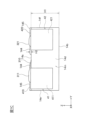
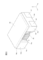
図1Aは本発明の一実施形態に係るコイル装置の全体斜視図である。FIG. 1A is an overall perspective view of a coil device according to an embodiment of the present invention. 図1Bは図1Aに示すコイル装置の平面図である。FIG. 1B is a plan view of the coil device shown in FIG. 1A. 図1Cは図1Aに示すコイル装置をIC方向から見た側面図である。FIG. 1C is a side view of the coil device shown in FIG. 1A viewed from the IC direction. 図2Aは図1Aに示すコイル装置を製造する過程を示す斜視図である。FIG. 2A is a perspective view showing a process of manufacturing the coil device shown in FIG. 1A. 図2Bは図2Aの続きの工程を示す斜視図である。FIG. 2B is a perspective view showing a step continued from FIG. 2A. 図2Cは図2Bの続きの工程を示す斜視図である。FIG. 2C is a perspective view showing a step continued from FIG. 2B. 図2Dは図2Cの続きの工程を示す斜視図である。FIG. 2D is a perspective view showing a step continued from FIG. 2C. 図2Eは図2Dの続きの工程を示す斜視図である。FIG. 2E is a perspective view showing a step continued from FIG. 2D. 図2Fは図2Eの続きの工程を示す斜視図である。FIG. 2F is a perspective view showing a step continued from FIG. 2E. 図2Gは図2Fの続きの工程を示す斜視図である。FIG. 2G is a perspective view showing a step continued from FIG. 2F. 図2Hは図2Gの続きの工程を示す斜視図である。FIG. 2H is a perspective view showing a step continued from FIG. 2G. 図3は図2Gに示す工程の変形例を示す斜視図である。FIG. 3 is a perspective view showing a modification of the process shown in FIG. 2G. 図4は図1Aに示すコイル装置のコアを上方および下方の各々から見たときの相違を説明するための図である。FIG. 4 is a diagram for explaining the difference when the core of the coil device shown in FIG. 1A is viewed from above and below. 図5は図1Aに示すコイル装置を実装基板に実装したときの側面図である。FIG. 5 is a side view of the coil device shown in FIG. 1A mounted on a mounting board.

以下、本発明を、図面に示す実施形態に基づき説明する。 The present invention will be described below based on embodiments shown in the drawings.

図1Aに示すように、本発明の一実施形態に係るコイル装置1は、ドラムコア10と、ドラムコア10の巻芯部12に巻回されたコイル部30を有する。 As shown in FIG. 1A, a coil device 1 according to an embodiment of the present invention includes a drum core 10 and a coil portion 30 wound around a winding core portion 12 of the drum core 10.

以下の説明では、X軸はコイル装置1を実装する実装面と平行な面内で、ドラムコア10の巻芯部12の巻軸と平行な方向(第1方向)を示す。Y軸は、X軸と同じく実装面と平行な面内にありX軸と垂直な方向(第2方向)である。Z軸は、実装面の法線方向(第3方向)である。 In the following description, the X axis indicates a direction (first direction) parallel to the winding axis of the winding core 12 of the drum core 10 in a plane parallel to the mounting surface on which the coil device 1 is mounted. Like the X-axis, the Y-axis is in a plane parallel to the mounting surface and is perpendicular to the X-axis (second direction). The Z axis is the normal direction (third direction) of the mounting surface.

ドラムコア10は、巻芯部12と、巻芯部12のX軸方向の両端に備えられる一対の鍔部14m,14nと、を有する。一方の鍔部(第1鍔部)14mは、巻芯部12の軸方向(第1方向)の一方の端部に設けられている。他方の鍔部(第2鍔部)14nは、巻芯部12の軸方向の他方の端部に設けられ、第1鍔部14mと対向している。各鍔部14m,14nは、同一形状であるが、相互に異なっていてもよい。本実施形態では、各鍔部14m,14nは、点対称となるように配置してある。以下の説明において、鍔部14m,14nを特に区別する必要がない場合には、「鍔部14」と総称する。 The drum core 10 includes a winding core 12 and a pair of flanges 14m and 14n provided at both ends of the winding core 12 in the X-axis direction. One flange (first flange) 14m is provided at one end of the winding core 12 in the axial direction (first direction). The other flange (second flange) 14n is provided at the other end of the winding core 12 in the axial direction, and faces the first flange 14m. The flanges 14m and 14n have the same shape, but may be different from each other. In this embodiment, the respective flanges 14m and 14n are arranged point-symmetrically. In the following description, when there is no need to particularly distinguish between the flanges 14m and 14n, they will be collectively referred to as the "flange 14."

なお、以下の説明において、第1鍔部14mについては、X軸正方向側を「内側」とし、X軸負方向側を「外側」とする。また、第2鍔部14nについては、X軸負方向側を「内側」とし、X軸正方向側を「外側」とする。 In addition, in the following description, regarding the first flange portion 14m, the X-axis positive direction side is referred to as the "inside", and the X-axis negative direction side is referred to as the "outside". Further, regarding the second flange portion 14n, the side in the negative direction of the X-axis is defined as the "inside", and the side in the positive direction of the X-axis is defined as the "outside".

ドラムコア10(コイル装置1)のサイズは特に限定されないが、図1Bに示すように、そのX軸方向長さL0は1.46~1.86mmであり、Y軸方向幅W2は0.85~1.25mmであり、Z軸方向高さH1(図1C参照)は0.45~0.53mmである。図2Aに示す巻芯部12のY軸方向幅W3と、図1Bに示す鍔部14m,14nのY軸方向幅W2との比W3/W2は、好ましくは0.6~0.9である。なお、図1Cにおいて、高さH1には、後述する主隆起部144および副隆起部145の高さH2は含まれていない。 The size of the drum core 10 (coil device 1) is not particularly limited, but as shown in FIG. 1B, the length L0 in the X-axis direction is 1.46 to 1.86 mm, and the width W2 in the Y-axis direction is 0.85 to 0.85 mm. The height H1 in the Z-axis direction (see FIG. 1C) is 0.45 to 0.53 mm. The ratio W3/W2 between the width W3 in the Y-axis direction of the winding core 12 shown in FIG. 2A and the width W2 in the Y-axis direction of the flanges 14m and 14n shown in FIG. 1B is preferably 0.6 to 0.9. . Note that in FIG. 1C, the height H1 does not include the height H2 of the main raised portion 144 and the sub raised portion 145, which will be described later.

巻芯部12は、X軸方向に巻軸を持ち、Y軸方向に細長い略六角形状の断面を持つ。巻芯部12の横断面形状は、本実施形態では略六角形であるが、矩形や円形、あるいは略八角形でもよく、その横断面形状は特に限定されない。巻芯部12のY軸方向の略中心部に位置する外周面の一部は、外側に向けて凸状に突出している。これにより、その突出分だけ巻芯部12の横断面積を確保することが可能となり、コイル装置1のインダクタンス特性を良好にすることが可能となっている。以下の説明において、巻芯部12の上方側に位置する外周面を上面と呼び、巻芯部12の下方側に位置する外周面を下面と呼び、巻芯部12の側方側に位置する外周面を側面と呼ぶ。 The winding core portion 12 has a winding axis in the X-axis direction and a substantially hexagonal cross section elongated in the Y-axis direction. The cross-sectional shape of the winding core 12 is approximately hexagonal in this embodiment, but may be rectangular, circular, or approximately octagonal, and the cross-sectional shape is not particularly limited. A portion of the outer peripheral surface of the winding core 12 located approximately at the center in the Y-axis direction protrudes outward in a convex shape. Thereby, it is possible to secure the cross-sectional area of the winding core 12 by the amount of the protrusion, and it is possible to improve the inductance characteristics of the coil device 1. In the following description, the outer peripheral surface located on the upper side of the winding core 12 will be referred to as the upper surface, and the outer peripheral surface located on the lower side of the winding core 12 will be referred to as the lower surface, and the outer peripheral surface located on the lateral side of the winding core 12 will be referred to as the lower surface. The outer peripheral surface is called the side surface.

図1Aに示すように、巻芯部12には、第1ワイヤ31および第2ワイヤ32が巻回してあり、ワイヤ31,32を1層以上(本実施形態では2層)に巻回してなるコイル部30を構成している。ワイヤ31,32は、たとえば被覆導線で構成してあり、良導体からなる芯材を絶縁性の被覆膜で覆った構成を有している。本実施形態では、ワイヤ31,32における導体部分の横断面積は同一であるが、異なっていてもよい。また、コイル部30は、1本のワイヤを1層以上に巻回して構成してもよく、あるいは3本以上のワイヤを1層以上に巻回して構成してもよい。 As shown in FIG. 1A, a first wire 31 and a second wire 32 are wound around the winding core 12, and the wires 31 and 32 are wound in one or more layers (two layers in this embodiment). It constitutes the coil section 30. The wires 31 and 32 are made of, for example, coated conducting wires, and have a structure in which a core material made of a good conductor is covered with an insulating coating film. In this embodiment, the cross-sectional areas of the conductor portions in the wires 31 and 32 are the same, but may be different. Further, the coil portion 30 may be configured by winding one wire in one or more layers, or may be configured by winding three or more wires in one or more layers.

本実施形態では、ワイヤ31,32の巻回数が略同じであるが、用途によっては異ならせても良い。なお、ワイヤ31,32の巻回数が略同じとは、これらの巻回数の比が0.75~1/0.75の範囲内であり、好ましくは1である。 In this embodiment, the number of turns of the wires 31 and 32 is approximately the same, but the number of turns may be different depending on the application. Note that the wires 31 and 32 have substantially the same number of turns when the ratio of these numbers of turns is within a range of 0.75 to 1/0.75, preferably 1.

鍔部14の外形状は、Y軸方向に長い略直方体状(略矩形状)であり、鍔部14m,14nは、X軸方向に所定の間隔を空けて、互いに略平行になるように配置されている。図1Bに示すように、鍔部14を実装面側(本実施形態では、Z軸上側)から見たときに、鍔部14は、その四隅が丸みを帯びるように形成してある。なお、鍔部14の横断面(YZ断面)形状は、円形状や略八角形状でも良く、その横断面形状は特に限定されない。 The outer shape of the flange portion 14 is a substantially rectangular parallelepiped (substantially rectangular shape) long in the Y-axis direction, and the flange portions 14m and 14n are arranged substantially parallel to each other with a predetermined interval in the X-axis direction. has been done. As shown in FIG. 1B, the flange 14 is formed so that its four corners are rounded when the flange 14 is viewed from the mounting surface side (in this embodiment, from the Z-axis upper side). Note that the cross-sectional shape (YZ cross-section) of the collar portion 14 may be circular or approximately octagonal, and the cross-sectional shape is not particularly limited.

鍔部14は、上面(第1面)14aと、下面(第2面)14bと、内端面14cと、外端面14dと、第1横側面14eと、第2横側面14fとを有する。上面14aは、鍔部14の上方側に位置する面である。下面14bは、上面14aとはZ軸方向の反対側に位置する面である。内端面14cは、巻芯部12側に位置する面である。外端面14dは、内端面14cとはX軸方向の反対側に位置する面である。第1横側面14eは、上面14aおよび内端面14cに直交し、後述する第1端子電極41が位置する側の面である。第2横側面14fは、上面14aおよび内端面14cに直交し、後述する第2端子電極42が位置する側の面である。 The collar portion 14 has an upper surface (first surface) 14a, a lower surface (second surface) 14b, an inner end surface 14c, an outer end surface 14d, a first lateral surface 14e, and a second lateral surface 14f. The upper surface 14a is a surface located above the collar portion 14. The lower surface 14b is a surface located on the opposite side in the Z-axis direction from the upper surface 14a. The inner end surface 14c is a surface located on the winding core 12 side. The outer end surface 14d is a surface located on the opposite side in the X-axis direction from the inner end surface 14c. The first lateral side surface 14e is perpendicular to the upper surface 14a and the inner end surface 14c, and is a surface on which a first terminal electrode 41, which will be described later, is located. The second lateral side surface 14f is perpendicular to the upper surface 14a and the inner end surface 14c, and is a surface on the side where a second terminal electrode 42, which will be described later, is located.

本実施形態では、上面14aは、コイル装置1を回路基板などに実装する場合における実装面(接地面)となる。なお、図示の例では、第1鍔部14mの第2横側面14fと第2鍔部14nの第1横側面14eが面一となっているが、横側面14e,14fの間にY軸方向のずれがあってもよい。 In this embodiment, the upper surface 14a becomes a mounting surface (ground surface) when the coil device 1 is mounted on a circuit board or the like. In the illustrated example, the second lateral side surface 14f of the first flange portion 14m and the first lateral side surface 14e of the second flange portion 14n are flush with each other, but there is a gap between the lateral side surfaces 14e and 14f in the Y-axis direction. There may be a deviation.

図2Aに示すように、巻芯部12と鍔部14とが交わる位置には、凹状角部16が形成されている。凹状角部16は、巻芯部12の外周面と鍔部14の内端面14cとで形成された角状の部分であり、巻芯部12の外周方向に沿って、巻芯部12の周囲を一周するように形成されている。以下では、凹状角部16のうち、特に、巻芯部12の側面(第2横側面14f側に位置する側面)と鍔部14の内端面14cとで形成された凹状角部を第1凹状角部161と呼び、巻芯部12を挟んで第1凹状角部161のY軸方向の反対側に位置する凹状角部を第2凹状角部162と呼び、巻芯部12の上面と鍔部14の内端面14cとで形成された凹状角部を第3凹状角部163と呼ぶ。 As shown in FIG. 2A, a concave corner 16 is formed at a position where the winding core 12 and the flange 14 intersect. The concave corner portion 16 is an angular portion formed by the outer circumferential surface of the winding core portion 12 and the inner end surface 14c of the collar portion 14, and extends around the winding core portion 12 along the outer circumferential direction of the winding core portion 12. It is formed to go around the Below, among the concave corner parts 16, the concave corner part formed by the side surface of the winding core part 12 (the side surface located on the second lateral side surface 14f side) and the inner end surface 14c of the flange part 14 will be described as the first concave corner part 16. A concave corner located on the opposite side of the first concave corner 161 in the Y-axis direction with the winding core 12 in between is called a second concave corner 162. The concave corner formed with the inner end surface 14c of the portion 14 is referred to as a third concave corner 163.

第1凹状角部161は、後述する第1引出部310あるいは第2引出部320(図1A参照)が巻芯部12から離れる側(巻芯部12の側方側)に位置する。第2凹状角部162は、巻芯部12の側面(第1横側面14e側に位置する側面)と鍔部14の内端面14cとで形成された凹状角部に対応する。 The first concave corner portion 161 is located on the side where a first drawer portion 310 or a second drawer portion 320 (see FIG. 1A), which will be described later, is away from the winding core portion 12 (lateral side of the winding core portion 12). The second concave corner 162 corresponds to a concave corner formed by the side surface of the winding core 12 (the side surface located on the first lateral side 14e side) and the inner end surface 14c of the flange 14.

第1凹状角部161および第2凹状角部162は、凹状角部16の側方部を構成し、Z軸方向(鍔部14の高さ方向)に沿って形成されている。第3凹状角部163は、凹状角部16の上方部を構成し、Y軸方向に沿って形成されている。 The first recessed corner portion 161 and the second recessed corner portion 162 constitute the side portions of the recessed corner portion 16 and are formed along the Z-axis direction (height direction of the collar portion 14). The third concave corner 163 constitutes the upper part of the concave corner 16 and is formed along the Y-axis direction.

本実施形態では、鍔部14の上面14aのX軸方向に沿う幅が、鍔部14のY軸方向の一端側と他端側とで異なっている。すなわち、図1Bに示すように、後述する第1端子電極41が位置する上面14aの一端側のX軸方向に沿う幅をW1Aとし、後述する第2端子電極42が位置する上面14aの他端側のX軸方向に沿う幅をW1Bとしたときに、上面14aの他端側のX軸方向に沿う幅W1Bは、上面14aの一端側のX軸方向に沿う幅W1Aよりも小さい(W1B<W1A)。 In this embodiment, the width of the upper surface 14a of the collar portion 14 along the X-axis direction is different between one end side and the other end side of the collar portion 14 in the Y-axis direction. That is, as shown in FIG. 1B, the width along the X-axis direction of one end of the upper surface 14a where a first terminal electrode 41 (described later) is located is W1A, and the other end of the upper surface 14a where a second terminal electrode 42 (described later) is located. When the width along the X-axis direction of the side is defined as W1B, the width W1B along the X-axis direction on the other end side of the top surface 14a is smaller than the width W1A along the X-axis direction on the one end side of the top surface 14a (W1B< W1A).

なお、上面14aのY軸方向の一端側のX軸方向に沿う幅W1Aは、鍔部14の外端面14dと、鍔部14のY軸方向の一端側に位置する内端面14cとの間の長さに対応する。また、鍔部14のY軸方向の他端側のX軸方向に沿う幅W1Bは、鍔部14の外端面14dと、鍔部14のY軸方向の他端側に位置する内端面14cとの間の長さに対応する。 Note that the width W1A along the X-axis at one end of the upper surface 14a in the Y-axis direction is the width W1A between the outer end surface 14d of the flange 14 and the inner end surface 14c located at one end of the flange 14 in the Y-axis direction. corresponds to the length. Moreover, the width W1B along the X-axis direction on the other end side in the Y-axis direction of the collar portion 14 is the width W1B of the outer end surface 14d of the collar portion 14 and the inner end surface 14c located on the other end side of the collar portion 14 in the Y-axis direction. Corresponds to the length between.

鍔部14の上面14aのY軸方向の一端側におけるX軸方向に沿う幅W1Aは、好ましくは0.45cm~0.51cmである。鍔部14の上面14aのY軸方向の他端側におけるX軸方向に沿う幅W1Bは、幅W1Aよりも小さく、好ましくは0.26cm~0.36cmである。幅W1Bと幅W1Aとの比W1B/W1Aは、好ましくは、0.5以上1未満であり、さらに好ましくは、0.7以上0.9未満である。第1ワイヤ31または第2ワイヤ32の直径をdとしたときに、幅W1Aと幅W1Bとの差分である幅W1Cの大きさは、好ましくはW1C≧dであり、さらに好ましくはW1C≧2dである。 The width W1A along the X-axis direction at one end side in the Y-axis direction of the upper surface 14a of the flange portion 14 is preferably 0.45 cm to 0.51 cm. The width W1B along the X-axis direction on the other end side of the upper surface 14a of the flange portion 14 in the Y-axis direction is smaller than the width W1A, and is preferably 0.26 cm to 0.36 cm. The ratio W1B/W1A between the width W1B and the width W1A is preferably 0.5 or more and less than 1, and more preferably 0.7 or more and less than 0.9. When the diameter of the first wire 31 or the second wire 32 is d, the width W1C, which is the difference between the width W1A and the width W1B, preferably satisfies W1C≧d, more preferably W1C≧2d. be.

本実施形態では、W1B<W1Aであるため、鍔部14のY軸方向の他端側に位置する内端面14cの一部は、鍔部14のY軸方向の一端側に位置する内端面14cの一部よりも、X軸方向に沿って、鍔部14の外端面14d側に位置ずれして配置される。鍔部14のY軸方向の他端側に位置する内端面14cの一部と、鍔部14のY軸方向の一端側に位置する内端面14cの一部との間のずれ幅は、前述の幅W1AとW1Bとの差分である幅W1Cに対応する。図示の例では、上記ずれ幅は、第2ワイヤ32の直径の2~3倍となっているが、それ以上であってもよい。 In this embodiment, since W1B<W1A, a part of the inner end surface 14c located on the other end side of the flange 14 in the Y-axis direction is It is disposed at a position shifted toward the outer end surface 14d of the flange 14 along the X-axis direction than a part of the flange 14 . The deviation width between a portion of the inner end surface 14c located on the other end side of the collar portion 14 in the Y-axis direction and a portion of the inner end surface 14c located on one end side of the collar portion 14 in the Y-axis direction is as described above. It corresponds to the width W1C which is the difference between the widths W1A and W1B. In the illustrated example, the deviation width is two to three times the diameter of the second wire 32, but may be larger.

また、第1凹状角部161は、第2凹状角部162よりも、X軸方向に沿って、鍔部14の外端面14d側に位置ずれしている。第1凹状角部161と第2凹状角部162との間のずれ幅は、前述の幅W1Aと幅W1Bとの差分である幅W1Cに対応する。 Further, the first concave corner portion 161 is shifted from the second concave corner portion 162 toward the outer end surface 14d of the collar portion 14 along the X-axis direction. The deviation width between the first recessed corner portion 161 and the second recessed corner portion 162 corresponds to the width W1C, which is the difference between the width W1A and the width W1B described above.

図4に示すように、本実施形態では、鍔部14の上面14a側におけるX軸方向に沿う幅(最大幅)W2Aと、鍔部14の下面14b側におけるX軸方向に沿う幅(最大幅)W2Bとは異なっている。より詳細には、上記幅W2Aは、上記幅W2Bよりも大きくなっている。上記幅W2Aと上記幅W2Bとの差分W2A-W2Bは、好ましくはW2A-W2B≧dであり、さらに好ましくはW2A-W2B≧2dである。ただし、dは第1ワイヤ31または第2ワイヤ32の直径である。 As shown in FIG. 4, in this embodiment, the width (maximum width) W2A along the X-axis direction on the upper surface 14a side of the collar portion 14, and the width (maximum width) along the X-axis direction on the lower surface 14b side of the collar portion 14 ) It is different from W2B. More specifically, the width W2A is larger than the width W2B. The difference W2A-W2B between the width W2A and the width W2B is preferably W2A-W2B≧d, and more preferably W2A-W2B≧2d. However, d is the diameter of the first wire 31 or the second wire 32.

また、上記幅W2A,W2Bの関係に対応して、巻芯部12の上面側におけるX軸方向に沿う長さL1Aと、巻芯部12の下面側におけるX軸方向に沿う長さL1Bとは異なっている。より詳細には、上記長さL1Aは、上記長さL1Bよりも小さくなっている。上記長さL1Bと上記長さL1Aとの差分L1B-L1Aは、好ましくはL1B-L1A≧dであり、さらに好ましくはL1B-L1A≧2dである。 Furthermore, corresponding to the relationship between the widths W2A and W2B, the length L1A along the X-axis direction on the upper surface side of the winding core 12 and the length L1B along the X-axis direction on the lower surface side of the winding core 12 are It's different. More specifically, the length L1A is smaller than the length L1B. The difference L1B-L1A between the length L1B and the length L1A is preferably L1B-L1A≧d, and more preferably L1B-L1A≧2d.

図1Bおよび図1Cに示すように、鍔部14の上面14a(実装面)には、第1端子電極41が形成してある。第1鍔部14mに形成してある第1端子電極41と、第2鍔部14nに形成してある第1端子電極41とは、同様の構成を有する。第1端子電極41は、第1上面電極部410と、第1側面電極部411とからなり、これらは電気的に接続されている。より詳細には、第1上面電極部410は、XY平面に平行な面を有し、鍔部14の上面14aのY軸方向の一端に形成してある。第1上面電極部410の一部は、後述する第1傾斜部141に入り込むように形成してある。また、第1側面電極部411は、YZ平面に平行な面を有し、鍔部14の端面14dに形成してある。第1側面電極部411を鍔部14に形成することにより、第1端子電極41に十分な半田フィレットを形成することが可能となる。 As shown in FIGS. 1B and 1C, a first terminal electrode 41 is formed on the upper surface 14a (mounting surface) of the collar portion 14. The first terminal electrode 41 formed on the first flange 14m and the first terminal electrode 41 formed on the second flange 14n have the same configuration. The first terminal electrode 41 includes a first upper surface electrode section 410 and a first side surface electrode section 411, which are electrically connected. More specifically, the first upper electrode section 410 has a surface parallel to the XY plane, and is formed at one end of the upper surface 14a of the collar section 14 in the Y-axis direction. A portion of the first upper surface electrode section 410 is formed so as to fit into a first inclined section 141, which will be described later. Further, the first side electrode portion 411 has a surface parallel to the YZ plane, and is formed on the end surface 14d of the collar portion 14. By forming the first side electrode portion 411 on the flange portion 14, it becomes possible to form a sufficient solder fillet on the first terminal electrode 41.

第1鍔部14mに形成してある第1上面電極部410には、第1ワイヤ31の第1引出部310との接続部分である第1継線部311が形成してある。第2鍔部14nに形成してある第1上面電極部410には、第2ワイヤ32の第2引出部320との接続部分である第2継線部321が形成してある。継線部311,321は、引出部310,320を第1上面電極部410に熱圧着することにより形成される。本実施形態では、第1上面電極部410は、回路基板(図示略)の表面と向き合って接続される実装部としての機能も有する。より詳細には、第1上面電極部410のうち、継線部311,321が形成されていない部分が、回路基板の電極(ランド)との半田の良接合面として機能する。 A first connecting portion 311, which is a connecting portion to the first lead-out portion 310 of the first wire 31, is formed on the first upper surface electrode portion 410 formed on the first collar portion 14m. A second connection portion 321, which is a connection portion to the second lead-out portion 320 of the second wire 32, is formed on the first upper surface electrode portion 410 formed on the second collar portion 14n. The connecting parts 311 and 321 are formed by thermocompression bonding the lead-out parts 310 and 320 to the first upper electrode part 410. In this embodiment, the first upper electrode section 410 also functions as a mounting section that faces and is connected to the surface of a circuit board (not shown). More specifically, the portion of the first upper electrode portion 410 where the connecting wire portions 311 and 321 are not formed functions as a good solder joint surface with the electrode (land) of the circuit board.

なお、一般的には、熱圧着した部分では、はんだ濡れ性が低下する。そのため、継線部311,321は、第1上面電極部410の中央ではなく、端部に配置されることが好ましい。本実施形態では、継線部311,321は、鍔部14の外端面14dの近傍に配置されている。これにより、第1上面電極部410のうち、はんだ濡れ性に優れた部分の面積を十分に大きく確保することが可能となり、コイル装置と回路基板との接合強度(固着強度)を高めることができる。また、コイル装置1を小型化した場合であっても、回路基板との固着強度を十分に確保することができる。 Note that solder wettability generally decreases in the thermocompression bonded portion. Therefore, it is preferable that the connecting wire parts 311 and 321 be arranged at the ends of the first upper electrode part 410, rather than at the center. In this embodiment, the connecting wire parts 311 and 321 are arranged near the outer end surface 14d of the collar part 14. This makes it possible to secure a sufficiently large area of the portion of the first upper electrode section 410 with excellent solder wettability, thereby increasing the bonding strength (fixing strength) between the coil device and the circuit board. . Further, even when the coil device 1 is miniaturized, it is possible to ensure sufficient adhesion strength to the circuit board.

鍔部14の上面14aには、第2端子電極42が、第1端子電極41とはY軸方向に沿って所定間隔をあけて(離間して)形成してある。第1鍔部14mに形成してある第2端子電極42と、第2鍔部14nに形成してある第2端子電極42とは、同様の構成を有する。なお、第1端子電極41と第2端子電極42の間隔は、絶縁が確保される距離であれば特に限定されない。 A second terminal electrode 42 is formed on the upper surface 14a of the flange 14 at a predetermined interval (separated) from the first terminal electrode 41 along the Y-axis direction. The second terminal electrode 42 formed on the first flange 14m and the second terminal electrode 42 formed on the second flange 14n have the same configuration. Note that the distance between the first terminal electrode 41 and the second terminal electrode 42 is not particularly limited as long as insulation is ensured.

本実施形態では、第2端子電極42は、第2上面電極部420と、第2側面電極部421とからなり、これらは電気的に接続されている。より詳細には、第2上面電極部420は、XY平面に平行な面を有し、鍔部14の上面14aのY軸方向の他端(第1上面電極部410とはY軸方向の反対側)に形成してある。第2上面電極部420の一部は、後述する第2傾斜部142に入り込むように形成してある。また、第2側面電極部421は、YZ平面に平行な面を有し、鍔部14の端面14dに形成してある。第2側面電極部421を鍔部14に形成することにより、第2端子電極42に十分な半田フィレットを形成することが可能となる。 In this embodiment, the second terminal electrode 42 includes a second upper surface electrode section 420 and a second side surface electrode section 421, which are electrically connected. More specifically, the second upper surface electrode section 420 has a surface parallel to the XY plane, and is located at the other end of the upper surface 14a of the collar section 14 in the Y-axis direction (opposite to the first upper surface electrode section 410 in the Y-axis direction). side). A portion of the second upper surface electrode section 420 is formed so as to fit into a second inclined section 142, which will be described later. Further, the second side electrode portion 421 has a surface parallel to the YZ plane, and is formed on the end surface 14d of the collar portion 14. By forming the second side electrode portion 421 on the flange portion 14, it becomes possible to form a sufficient solder fillet on the second terminal electrode 42.

第1鍔部14mに形成してある第2上面電極部420には、第2ワイヤ32の第2引出部320との接続部分である第2継線部321が形成してある。第2鍔部14nに形成してある第2上面電極部420には、第1ワイヤ31の第1引出部310との接続部分である第1継線部311が形成してある。継線部311,321は、引出部310,320を第2上面電極部420に熱圧着することにより形成される。本実施形態では、第2上面電極部420は、回路基板(図示略)の表面と向き合って接続される実装部としての機能も有する。より詳細には、第2上面電極部420のうち、継線部311,321が形成されていない部分が、回路基板の電極(ランド)との半田の良接合面として機能する。 A second connecting wire portion 321, which is a connecting portion to the second lead-out portion 320 of the second wire 32, is formed on the second upper surface electrode portion 420 formed on the first collar portion 14m. A first wire connecting portion 311, which is a connecting portion to the first lead-out portion 310 of the first wire 31, is formed on the second upper surface electrode portion 420 formed on the second collar portion 14n. The connecting parts 311 and 321 are formed by thermocompression bonding the lead parts 310 and 320 to the second upper electrode part 420. In this embodiment, the second upper electrode section 420 also functions as a mounting section that faces and is connected to the surface of a circuit board (not shown). More specifically, the portion of the second upper surface electrode portion 420 where the connecting wire portions 311 and 321 are not formed functions as a good solder joint surface with the electrode (land) of the circuit board.

なお、継線部311,321は、第2上面電極部420の中央ではなく、端部に配置されることが好ましい。本実施形態では、継線部311,321は、鍔部14の外端面14dの近傍に配置されている。これにより、第2上面電極部420のうち、はんだ濡れ性に優れた部分の面積を十分に大きく確保することが可能となり、コイル装置と回路基板との固着強度を高めることができる。また、コイル装置1を小型化した場合であっても、回路基板との固着強度を十分に確保することができる。 Note that it is preferable that the connecting wire parts 311 and 321 be arranged at the ends of the second upper electrode part 420, rather than at the center. In this embodiment, the connecting wire parts 311 and 321 are arranged near the outer end surface 14d of the collar part 14. This makes it possible to secure a sufficiently large area of the portion of the second upper surface electrode portion 420 with excellent solder wettability, and it is possible to increase the adhesion strength between the coil device and the circuit board. Further, even when the coil device 1 is miniaturized, it is possible to ensure sufficient adhesion strength to the circuit board.

第1端子電極41および第2端子電極42は、たとえば金属ペースト焼付け膜や金属メッキ膜で構成されている。端子電極41,42は、鍔部14の上面14aおよび外端面14dの表面に、たとえばAgペーストを塗布して焼き付けた後、その表面に、たとえば電界メッキまたは無電界メッキを施し、メッキ膜を形成することにより形成される。 The first terminal electrode 41 and the second terminal electrode 42 are made of, for example, a baked metal paste film or a metal plated film. The terminal electrodes 41 and 42 are formed by applying, for example, Ag paste to the surfaces of the upper surface 14a and the outer end surface 14d of the flange portion 14 and baking it, and then applying, for example, electrolytic plating or electroless plating to the surfaces to form a plating film. It is formed by

なお、金属ペーストの材料は、特に限定されるものではなく、CuペーストやAgペーストなどが例示される。また、メッキ膜は、単層でも複層でも良く、たとえばCuメッキ、Niメッキ、Snメッキ、Ni-Snメッキ、Cu-Ni-Snメッキ、Ni-Auメッキ、Auメッキなどのメッキ膜が例示される。端子電極41,42の厚みは、特に限定されないが、好ましくは0.1~15μmである。 Note that the material of the metal paste is not particularly limited, and examples include Cu paste and Ag paste. Further, the plating film may be a single layer or a multilayer, and examples include plating films such as Cu plating, Ni plating, Sn plating, Ni-Sn plating, Cu-Ni-Sn plating, Ni-Au plating, and Au plating. Ru. The thickness of the terminal electrodes 41, 42 is not particularly limited, but is preferably 0.1 to 15 μm.

図2Aに示すように、鍔部14には、第1傾斜部141と第2傾斜部142とが形成してある。第1鍔部14mに形成してある第1傾斜部141と、第2鍔部14nに形成してある第1傾斜部141とは、同様の構成からなる。また、第1鍔部14mに形成してある第2傾斜部142と、第2鍔部14nに形成してある第2傾斜部142とは、同様の構成からなる。本実施形態では、第1鍔部14mに形成してある各傾斜部141,142と、第2鍔部14nに形成してある各傾斜部141,142とは、点対称となるように配置してある。 As shown in FIG. 2A, the collar portion 14 is formed with a first inclined portion 141 and a second inclined portion 142. The first inclined portion 141 formed on the first collar portion 14m and the first inclined portion 141 formed on the second collar portion 14n have the same configuration. Further, the second slope portion 142 formed on the first flange portion 14m and the second slope portion 142 formed on the second flange portion 14n have the same configuration. In this embodiment, each inclined part 141, 142 formed on the first flange 14m and each inclined part 141, 142 formed on the second flange 14n are arranged point-symmetrically. There is.

第1傾斜部141は、巻芯部12の上面と鍔部14の上面14aとの間の範囲に形成されており、Y軸方向に対して、Z軸方向に傾斜して延びている。第1傾斜部141の中心軸の延長線C1は、鍔部14の第1横側面14eと交差するとともに、後述する段差面149(図2B参照)の周縁部1490と交差する。 The first inclined portion 141 is formed in a range between the upper surface of the winding core portion 12 and the upper surface 14a of the flange portion 14, and extends obliquely in the Z-axis direction with respect to the Y-axis direction. An extension line C1 of the central axis of the first inclined portion 141 intersects with the first lateral side surface 14e of the collar portion 14, and also intersects with a peripheral edge portion 1490 of a stepped surface 149 (see FIG. 2B), which will be described later.

第1傾斜部141は、第1傾斜面1410と第1壁側側面1411とを有する。第1傾斜面1410は、鍔部14のY軸方向一端側からY軸方向他端側に向かって傾斜する傾斜面からなる。第1傾斜部141の位置では、鍔部14の内端面14cは、第1傾斜面1410によって切り欠かれている。 The first inclined portion 141 has a first inclined surface 1410 and a first wall-side side surface 1411. The first inclined surface 1410 is an inclined surface that is inclined from one end in the Y-axis direction of the collar portion 14 toward the other end in the Y-axis direction. At the position of the first inclined portion 141, the inner end surface 14c of the collar portion 14 is cut out by the first inclined surface 1410.

図2Bに示すように、第1傾斜部141の始端141sは、鍔部14のY軸方向の中心よりもY軸方向の他端側に位置しており、第1傾斜部141の終端141eは、鍔部14のY軸方向の中心よりもY軸方向の一端側に位置している。 As shown in FIG. 2B, the starting end 141s of the first inclined part 141 is located on the other end side in the Y-axis direction with respect to the center of the collar part 14 in the Y-axis direction, and the terminal end 141e of the first inclined part 141 is , is located closer to one end in the Y-axis direction than the center of the collar portion 14 in the Y-axis direction.

第1傾斜面1410は、第1傾斜部141の始端141sから終端141eに向かうにしたがってX軸方向に向かって幅広となるように形成されており、第1傾斜部1410の終端部(終端141eの周辺部)では、鍔部14の外端面14dの近傍から鍔部14の内端面14cにかけて形成されている。第1傾斜面1410の終端141eにおいて、第1傾斜面1410のX軸方向の端部と鍔部14の外端面14dとの間の距離をLとすると、上記距離Lと、鍔部14の上面14aの一端側のX軸方向に沿う幅W1Aとの比L/W1Aは、好ましくは0~0.2である。 The first inclined surface 1410 is formed to become wider in the X-axis direction as it goes from the starting end 141s to the terminal end 141e of the first inclined section 141. In the peripheral portion), it is formed from the vicinity of the outer end surface 14d of the collar portion 14 to the inner end surface 14c of the collar portion 14. At the terminal end 141e of the first inclined surface 1410, if the distance between the end of the first inclined surface 1410 in the X-axis direction and the outer end surface 14d of the flange 14 is L, the above distance L and the upper surface of the flange 14 are The ratio L/W1A to the width W1A along the X-axis direction on one end side of 14a is preferably 0 to 0.2.

図2Aに示すように、第1壁側側面1411は、壁部143の一部を構成している。第1壁側側面1411は、切り立った壁面からなり、第1傾斜面1410の側方に沿って延びている。 As shown in FIG. 2A, the first wall-side side surface 1411 constitutes a part of the wall portion 143. The first wall-side side surface 1411 is made of a steep wall surface and extends along the side of the first inclined surface 1410.

第2傾斜部142は、鍔部14の外側(外端面14d)に向かって、第1傾斜部141とは異なる角度で斜めに延びており、徐々に下降するように傾斜している。第2傾斜部142の中心軸の延長線C2は、鍔部14の外端面14dと交差するとともに、第1凹状角部161に向かって延び、後述する段差面148(図2B参照)の周縁部1480と交差する。延長線C2とX軸との為す角度は、好ましくは18~24°である。なお、延長線C2の延在方向は、第2傾斜部142に沿って引き出される第2引出部320の引出方向と略等しくなっている(図1A参照)。 The second inclined part 142 extends obliquely toward the outside (outer end surface 14d) of the collar part 14 at an angle different from that of the first inclined part 141, and is inclined so as to gradually descend. An extension line C2 of the central axis of the second inclined portion 142 intersects the outer end surface 14d of the collar portion 14, extends toward the first concave corner portion 161, and extends to the peripheral edge of a stepped surface 148 (see FIG. 2B), which will be described later. Intersects with 1480. The angle between the extension line C2 and the X axis is preferably 18 to 24 degrees. Note that the extending direction of the extension line C2 is approximately equal to the drawing direction of the second drawing part 320 drawn out along the second inclined part 142 (see FIG. 1A).

第2傾斜部142は、溝形状(溝部)からなり、第2傾斜面1420と、第2壁側側面1421と、第2外側側面1422とを有する。第2傾斜面1420は、第2壁側側面1421と第2外側側面1422とで挟まれるように配置してあり、鍔部14の外端面14dから内端面14cに向かって傾斜する傾斜面からなる。 The second inclined portion 142 has a groove shape (groove portion) and includes a second inclined surface 1420, a second wall-side side surface 1421, and a second outer side surface 1422. The second inclined surface 1420 is arranged to be sandwiched between the second wall-side side surface 1421 and the second outer side surface 1422, and is formed of an inclined surface that slopes from the outer end surface 14d of the collar portion 14 toward the inner end surface 14c. .

第2壁側側面1421は、壁部143に隣接して形成されており、壁部143の一部を構成している。第2外側側面1422は、第2傾斜面1420を挟んで第2壁側側面1421とは反対側に形成してある。 The second wall-side side surface 1421 is formed adjacent to the wall portion 143 and constitutes a part of the wall portion 143. The second outer side surface 1422 is formed on the opposite side of the second wall side surface 1421 with the second inclined surface 1420 in between.

鍔部14には、段差面148と段差面149とが形成されている。段差面148は、略平面形状からなり、第3凹状角部163のY軸方向の他端側(第2横側面14f側)あるいは第1凹状角部161の上端付近に形成されている。 A stepped surface 148 and a stepped surface 149 are formed on the flange portion 14 . The stepped surface 148 has a substantially planar shape, and is formed near the other end of the third concave corner 163 in the Y-axis direction (the second lateral surface 14f side) or the upper end of the first concave corner 161.

図2Bに示すように、本実施形態では、段差面148の周縁部1480には、第2傾斜部142の第2始端142sが接続されている。第2傾斜部142の第2始端142sは、段差面148と、第2傾斜部142(第2傾斜面1420)との交差部に対応する。第2傾斜部142の第2終端142eは、鍔部14の上面14aと、第2傾斜部142(第2傾斜面1420)との交差部に対応する。 As shown in FIG. 2B, in this embodiment, the second starting end 142s of the second inclined portion 142 is connected to the peripheral edge 1480 of the stepped surface 148. The second starting end 142s of the second slope 142 corresponds to the intersection between the step surface 148 and the second slope 142 (second slope 1420). The second terminal end 142e of the second inclined portion 142 corresponds to the intersection between the upper surface 14a of the collar portion 14 and the second inclined portion 142 (second inclined surface 1420).

段差面149は、略平面形状からなり、鍔部14のY軸方向の中心部よりも他端側において、第3凹状角部163および壁部143に隣接して形成されている。段差面149の周縁部1490には、第1傾斜部141の第1始端141sが接続されている。第1傾斜部141の第1始端141sは、段差面149と、第1傾斜部141(第1傾斜面1410)との交差部に対応する。第1傾斜部141の第1終端141eは、鍔部14の上面14aと、第1傾斜部141(第1傾斜面1410)との交差部に対応する。 The stepped surface 149 has a substantially planar shape and is formed adjacent to the third concave corner portion 163 and the wall portion 143 on the other end side of the center portion of the flange portion 14 in the Y-axis direction. A first starting end 141s of the first inclined portion 141 is connected to a peripheral edge portion 1490 of the stepped surface 149. The first starting end 141s of the first inclined portion 141 corresponds to the intersection between the step surface 149 and the first inclined portion 141 (first inclined surface 1410). The first terminal end 141e of the first inclined portion 141 corresponds to the intersection between the upper surface 14a of the collar portion 14 and the first inclined portion 141 (first inclined surface 1410).

図1Aに示すように、本実施形態では、第1鍔部14mの第1傾斜部141には第1ワイヤ31の第1引出部310が通過し、第1鍔部14mの第2傾斜部142には第2ワイヤ32の第2引出部320が通過する。また、第2鍔部14nの第1傾斜部141には第2ワイヤ32の第2引出部320が通過し、第2鍔部14nの第2傾斜部142には第1ワイヤ31の第1引出部310が通過する。 As shown in FIG. 1A, in this embodiment, the first lead-out part 310 of the first wire 31 passes through the first inclined part 141 of the first collar part 14m, and the second inclined part 142 of the first collar part 14m passes through the first lead-out part 310 of the first wire 31. The second lead-out portion 320 of the second wire 32 passes through. Further, the second lead-out part 320 of the second wire 32 passes through the first inclined part 141 of the second collar part 14n, and the first lead-out part 320 of the first wire 31 passes through the second inclined part 142 of the second collar part 14n. section 310 passes through.

より詳細には、図1Aおよび図2Aに示すように、第1鍔部14m側において、第1ワイヤ31の第1引出部310は、巻芯部12の側面側で、巻芯部12(あるいは、コイル部30)から離れた後、段差面149側に向けて引き出される。そして、第1引出部310は、段差面149に接触することなくその上を通過し、第1傾斜部141の第1傾斜面1410(図2A参照)に沿って、第1端子電極41に向かって斜めに引き出される。より詳細には、第1引出部310は、第1傾斜部141の第1壁側側面1411に沿って、あるいは第1壁側側面1411に固定されつつ、第1端子電極41まで引き出される。 More specifically, as shown in FIGS. 1A and 2A, on the first flange 14m side, the first lead-out portion 310 of the first wire 31 is connected to the winding core 12 (or , the coil portion 30), and then pulled out toward the step surface 149 side. The first lead-out portion 310 then passes over the stepped surface 149 without contacting it, and heads toward the first terminal electrode 41 along the first inclined surface 1410 (see FIG. 2A) of the first inclined portion 141. It is pulled out diagonally. More specifically, the first drawn-out portion 310 is drawn out to the first terminal electrode 41 along the first wall-side side surface 1411 of the first inclined portion 141 or while being fixed to the first wall-side side surface 1411.

また、第1鍔部14m側において、第2ワイヤ32の第2引出部320は、巻芯部12の側面側で、巻芯部12(あるいは、コイル部30)から離れた後、段差面148側に向けて引き出される。そして、第2引出部320は、段差面148に接触することなくその上を通過し、第2傾斜部142の第2傾斜面1420に沿って、第2端子電極42(あるいは、鍔部14の外端面14d)に向かって、第1引出部310とは異なる角度で斜めに引き出される。 Further, on the first flange 14m side, the second lead-out part 320 of the second wire 32 is separated from the winding core 12 (or the coil part 30) on the side surface side of the winding core 12, and then extends to the stepped surface 148. pulled out to the side. Then, the second lead-out portion 320 passes over the stepped surface 148 without contacting it, and moves along the second inclined surface 1420 of the second inclined portion 142 to the second terminal electrode 42 (or the flange portion 14). It is pulled out diagonally toward the outer end surface 14d) at a different angle than the first pull-out part 310.

また、第2鍔部14n側において、第2ワイヤ32の第2引出部320は、巻芯部12の側面側で、巻芯部12(あるいは、コイル部30)から離れた後、段差面149側に向けて引き出される。そして、第2引出部320は、段差面149に接触することなくその上を通過し、第1傾斜部141の第1傾斜面1410に沿って、あるいは第1壁側側面1411に固定されつつ、第1端子電極41に向かって斜めに引き出される。 Further, on the second flange 14n side, the second lead-out portion 320 of the second wire 32 is separated from the winding core 12 (or the coil portion 30) on the side surface side of the winding core 12, and then extends to the stepped surface 149. pulled out to the side. The second drawer part 320 passes over the stepped surface 149 without contacting it, and is fixed along the first inclined surface 1410 of the first inclined section 141 or to the first wall-side side surface 1411. It is pulled out obliquely toward the first terminal electrode 41 .

また、第2鍔部14n側において、第1ワイヤ31の第1引出部310は、巻芯部12の側面側で、巻芯部12(あるいは、コイル部30)から離れた後、段差面148(図示略)側に向けて引き出される。そして、第1引出部310は、段差面148に接触することなくその上を通過し、第2傾斜部142の第2傾斜面1420に沿って、第2端子電極42(あるいは、鍔部14の外端面14d)に向かって、第2引出部320とは異なる角度で斜めに引き出される。 Further, on the second flange 14n side, the first lead-out part 310 of the first wire 31 is separated from the winding core 12 (or the coil part 30) on the side surface side of the winding core 12, and then extends to the stepped surface 148. (not shown). Then, the first lead-out portion 310 passes over the stepped surface 148 without contacting it, and moves along the second inclined surface 1420 of the second inclined portion 142 to the second terminal electrode 42 (or the collar portion 14). It is pulled out obliquely toward the outer end surface 14d) at a different angle from the second pull-out part 320.

前述の通り、本実施形態では、第1凹状角部161が、第2凹状角部162よりも、幅W1C(図1B参照)に応じた距離だけ、鍔部14の外端面14d側に位置ずれしている。そのため、巻芯部12のX軸負方向側の端部と段差面148との間の範囲において、第2引出部320を斜めに引き出すことが可能となり、第1凹状角部161の近傍において、第1引出部310および第2引出部320の各々をX軸方向に沿って離間して配置することが可能となっている。 As described above, in the present embodiment, the first concave corner 161 is shifted closer to the outer end surface 14d of the collar 14 than the second concave corner 162 by a distance corresponding to the width W1C (see FIG. 1B). are doing. Therefore, in the range between the end of the winding core part 12 on the negative side of the X-axis and the step surface 148, the second drawer part 320 can be pulled out obliquely, and in the vicinity of the first concave corner part 161, Each of the first drawer part 310 and the second drawer part 320 can be arranged apart from each other along the X-axis direction.

なお、第2ワイヤ32は、段差面148から第2傾斜部142の第2終端142eの手前にかけて空中配線され、第2傾斜部142の第2終端142eの手前で第2傾斜部142の底(第2傾斜面1420)に当接してもよい。 The second wire 32 is wired in the air from the step surface 148 to the front of the second end 142e of the second slope 142, and is connected to the bottom of the second slope 142 before the second end 142e of the second slope 142. The second inclined surface 1420) may be in contact with the second inclined surface 1420).

第1傾斜部141と第2傾斜部142とは、鍔部14に形成してある壁部143によって隔てられている。壁部143は、第1傾斜部141と第2傾斜部142との間に位置し、壁部143の一部は、後述する副隆起部144よりもX軸方向の内側に向かって突出している。そのため、第1引出部310は鍔部14の内端面14cから突出した壁部143の一部を迂回するように、第1傾斜部141に向かって引き出される。したがって、第1引出部310および第2引出部320の各々を十分に引き離し、第1引出部310と第2引出部320との接触を効果的に防止することが可能となっている。 The first inclined part 141 and the second inclined part 142 are separated by a wall part 143 formed on the collar part 14. The wall portion 143 is located between the first slope portion 141 and the second slope portion 142, and a portion of the wall portion 143 projects further inward in the X-axis direction than a sub-protrusion portion 144, which will be described later. . Therefore, the first drawer portion 310 is drawn out toward the first inclined portion 141 so as to bypass a portion of the wall portion 143 protruding from the inner end surface 14c of the collar portion 14. Therefore, it is possible to sufficiently separate each of the first drawer part 310 and the second drawer part 320 and effectively prevent the first drawer part 310 and the second drawer part 320 from coming into contact with each other.

図2Aに示すように、壁部143は、先端面1430と、第1側方面1431と、第2側方面1432とを有する。先端面1430は、YZ平面に略平行な壁面からなり、鍔部14の内端面14cの一部を構成している。先端面1430は、壁部143の先端部分を構成しており、その両側には第1側方面1431と第2側方面1432とが接続されている。第1側方面1431は、切り立った壁面からなり、第1傾斜部141の第1壁側側面1411に接続されている。第1側方面1431は、第1壁側側面1411に連続して接続されているが、不連続に接続されていてもよい。第2側方面1432は、XZ平面に略平行な壁面からなり、鍔部14の第2傾斜部の第2壁側側面1421に不連続に接続されている。 As shown in FIG. 2A, the wall portion 143 has a distal end surface 1430, a first side surface 1431, and a second side surface 1432. The tip surface 1430 is made of a wall surface substantially parallel to the YZ plane, and constitutes a part of the inner end surface 14c of the collar portion 14. The tip surface 1430 constitutes the tip portion of the wall portion 143, and a first side surface 1431 and a second side surface 1432 are connected to both sides thereof. The first side surface 1431 is made of a steep wall surface and is connected to the first wall side surface 1411 of the first inclined portion 141 . The first side surface 1431 is continuously connected to the first wall side surface 1411, but may be connected discontinuously. The second side surface 1432 is made of a wall surface substantially parallel to the XZ plane, and is discontinuously connected to the second wall side surface 1421 of the second inclined portion of the collar portion 14 .

本実施形態では、鍔部14の上面(第1面)14aには、隆起形状(凸形状あるいは突出形状)を有する主隆起部144が形成されている。主隆起部144は、鍔部14のY軸方向の他端側に形成されており、第1傾斜部141と第2傾斜部142とで挟まれた領域の内側に位置する。より詳細には、主隆起部144は、第1傾斜部141と第2傾斜部142とで挟まれた領域のうち、鍔部14のX軸方向の内側に形成されており、壁部143の上面の一部を構成している。 In this embodiment, a main raised portion 144 having a raised shape (convex shape or protruding shape) is formed on the upper surface (first surface) 14a of the collar portion 14. The main raised portion 144 is formed on the other end side of the collar portion 14 in the Y-axis direction, and is located inside a region sandwiched between the first inclined portion 141 and the second inclined portion 142. More specifically, the main raised portion 144 is formed on the inner side of the flange portion 14 in the X-axis direction in the region sandwiched between the first inclined portion 141 and the second inclined portion 142, and It forms part of the top surface.

鍔部14の上面14aのうち、主隆起部144が形成された位置では、当該位置の周囲に比べて、鍔部14aの上面14aの高さが高くなっている。主隆起部144の上面は平坦面となっており、鍔部14の上面14aのうち、主隆起部144が形成された位置と、主隆起部144が形成されていない位置との間(主隆起部144のX軸方向の外側端部)には段差が形成されている。 The height of the upper surface 14a of the collar portion 14a is higher at the position where the main raised portion 144 is formed than the surrounding area of the upper surface 14a of the collar portion 14. The upper surface of the main raised portion 144 is a flat surface, and between the position where the main raised portion 144 is formed and the position where the main raised portion 144 is not formed on the upper surface 14a of the collar portion 14 (main raised portion 144). A step is formed at the outer end of the portion 144 in the X-axis direction.

図1Cに示すように、主隆起部144の高さH2(鍔部14の上面14aのうち、主隆起部144の周辺部からの高さ)と、鍔部14の高さH1(鍔部14の上面14aのうち、主隆起部144の周辺部の高さ)との比H2/H1は、好ましくは0.01~0.08であり、さらに好ましくは0.03~0.06である。また、主隆起部144の高さH2と上記dとの比H2/dは、好ましくは0.3~1.3であり、さらに好ましくは0.5~1.0である。ただし、dは第1ワイヤ31または第2ワイヤ32の直径である。なお、図示の例では、主隆起部144の上面は平坦面となっているが、例えば山型に盛り上がるように形成されていてもよい。 As shown in FIG. 1C, the height H2 of the main raised part 144 (the height from the peripheral part of the main raised part 144 of the upper surface 14a of the collar part 14) and the height H1 of the collar part 14 (the height of the upper surface 14a of the collar part 14) The ratio H2/H1 to the height of the peripheral portion of the main raised portion 144 of the upper surface 14a is preferably 0.01 to 0.08, more preferably 0.03 to 0.06. Further, the ratio H2/d between the height H2 of the main raised portion 144 and the above d is preferably 0.3 to 1.3, more preferably 0.5 to 1.0. However, d is the diameter of the first wire 31 or the second wire 32. In the illustrated example, the upper surface of the main raised portion 144 is a flat surface, but it may be formed, for example, in a raised mountain shape.

図1Cにおいて、主隆起部144の高さH2は、第2端子電極42の第2上面電極部420に第2ワイヤ32の第2引出部320を接続したときに、第2引出部320の第2継線部321の一部が主隆起部144の上面よりも上方に突出する程度の高さとなっている。 In FIG. 1C, the height H2 of the main raised portion 144 is the height H2 of the second lead-out portion 320 of the second wire 32 when the second lead-out portion 320 of the second wire 32 is connected to the second upper surface electrode portion 420 of the second terminal electrode 42. The height is such that a part of the second joint portion 321 protrudes above the upper surface of the main raised portion 144.

図2Aに示すように、主隆起部144は、壁部143の一部を構成しており、壁部143の上面を上方に延長することにより構成される。主隆起部144の側面は、第1傾斜部141の第1壁側側面1411と、第2傾斜部142の第2壁側側面1421と、壁部143の先端面1430、第1側方面1431および第2側方面1432とで構成されている。主隆起部144の上面は、その周辺部に対して不連続(段差状)に接続されているが、連続的に接続されていてもよい。 As shown in FIG. 2A, the main raised portion 144 constitutes a part of the wall portion 143, and is configured by extending the upper surface of the wall portion 143 upward. The side surfaces of the main raised portion 144 include a first wall side surface 1411 of the first slope portion 141, a second wall side surface 1421 of the second slope portion 142, a tip surface 1430 of the wall portion 143, a first side surface 1431, and a second wall side surface 1421 of the second slope portion 142. and a second side surface 1432. The upper surface of the main raised portion 144 is connected discontinuously (step-shaped) to the peripheral portion thereof, but may be connected continuously.

図2Aに示すように、主隆起部144は、Z軸方向の上方から見たときに多角形状(図示の例では、五角形)を有しており、X軸方向の外側に向かうにしたがって幅広となるように形成されている。主隆起部144のX軸方向の最大幅W4と、鍔部14の上面14aの一端側のX軸方向に沿う幅W1A(図1B参照)との比W4/W1Aは、好ましくは0.2~0.5であり、さらに好ましくは0.3~0.4である。 As shown in FIG. 2A, the main protrusion 144 has a polygonal shape (in the illustrated example, a pentagon) when viewed from above in the Z-axis direction, and becomes wider toward the outside in the X-axis direction. It is formed to be. The ratio W4/W1A between the maximum width W4 of the main raised portion 144 in the X-axis direction and the width W1A (see FIG. 1B) along the X-axis of one end side of the upper surface 14a of the collar portion 14 is preferably 0.2 to 0.5, more preferably 0.3 to 0.4.

図2Bに示すように、本実施形態では、第2端子電極42の第2上面電極部420のX軸方向の内側端部は、主隆起部144のX軸方向の外側端部よりも外側に位置しており、第2上面電極部420と主隆起部144とは、X軸方向に沿って並んで配置されている。すなわち、主隆起部144には第2上面電極部420が形成されてはおらず、主隆起部144および第2上面電極部420は、それぞれ独立して(重複することなく)配置されている。また、主隆起部144は、第2端子電極42の第2上面電極部420に対応する位置に局所的に配置されている。 As shown in FIG. 2B, in this embodiment, the inner end of the second upper surface electrode portion 420 of the second terminal electrode 42 in the X-axis direction is located further outward than the outer end of the main raised portion 144 in the X-axis direction. The second upper surface electrode portion 420 and the main raised portion 144 are arranged side by side along the X-axis direction. That is, the second upper surface electrode section 420 is not formed on the main raised section 144, and the main raised section 144 and the second upper surface electrode section 420 are arranged independently (without overlapping). Further, the main raised portion 144 is locally arranged at a position corresponding to the second upper surface electrode portion 420 of the second terminal electrode 42 .

図1Aに示すように、第2ワイヤ32の第2引出部320は、主隆起部144よりもX軸方向の外側で第2端子電極42の第2上面電極部420に接続され、当該位置に第2継線部321が形成される。そのため、主隆起部144は、第2継線部321とコイル部30との間に配置されることになる。 As shown in FIG. 1A, the second lead-out portion 320 of the second wire 32 is connected to the second upper surface electrode portion 420 of the second terminal electrode 42 on the outer side of the main raised portion 144 in the X-axis direction, and is connected to the second upper electrode portion 420 of the second terminal electrode 42 at the position A second connection portion 321 is formed. Therefore, the main raised portion 144 is arranged between the second connecting wire portion 321 and the coil portion 30.

主隆起部144は、第1傾斜部141に沿って引き出される第1ワイヤ31の第1引出部310と、第2傾斜部142に沿って引き出される第2ワイヤ32の第2引出部320とで挟まれる領域の内側に位置する。主隆起部144は、Y軸方向に所定幅を有しており(図示の例では、鍔部14のY軸方向幅の1/4~1/3程度)、これにより主隆起部144の周囲を通過する第1引出部310と第2引出部320とを十分に引き離し、第1引出部310と第2引出部320との接触を防止することが可能となっている。 The main protrusion 144 includes a first lead-out part 310 of the first wire 31 drawn out along the first inclined part 141 and a second drawn-out part 320 of the second wire 32 drawn out along the second inclined part 142. Located inside the sandwiched area. The main raised portion 144 has a predetermined width in the Y-axis direction (in the illustrated example, approximately 1/4 to 1/3 of the width of the collar portion 14 in the Y-axis direction). It is possible to sufficiently separate the first drawer part 310 and the second drawer part 320 that pass through, thereby preventing the first drawer part 310 and the second drawer part 320 from coming into contact with each other.

図2Aに示すように、鍔部14の上面14aには、主隆起部144の他に副隆起部145が形成されている。副隆起部145は、隆起形状(凸形状あるいは突出形状)を有している。副隆起部145は、鍔部14のY軸方向の一端側に形成され、鍔部14のX軸方向の内側に位置している。副隆起部145は、第1傾斜部141よりもY軸方向の一端側に位置しており、第1傾斜部141は、主隆起部144と副隆起部145とで挟まれている。 As shown in FIG. 2A, in addition to the main protrusion 144, a sub-protrusion 145 is formed on the upper surface 14a of the flange 14. The sub-protruding portion 145 has a protruding shape (convex shape or protruding shape). The sub-protruding portion 145 is formed on one end side of the flange 14 in the Y-axis direction, and is located inside the flange 14 in the X-axis direction. The secondary raised part 145 is located closer to one end in the Y-axis direction than the first inclined part 141 , and the first inclined part 141 is sandwiched between the main raised part 144 and the secondary raised part 145 .

鍔部14の上面14aのうち、副隆起部145が形成された位置では、当該位置の周囲に比べて、鍔部14aの上面14aの高さが高くなっている。副隆起部145の上面は平坦面となっており、鍔部14の上面14aのうち、副隆起部145が形成された位置と、副隆起部145が形成されていない位置との間(副隆起部145のX軸方向の外側端部)には段差が形成されている。副隆起部145の高さと、主隆起部144の高さH2(図1C参照)とは略等しくなっている。なお、図示の例では、副隆起部145の上面は平坦面となっているが、例えば山型に盛り上がるように形成されていてもよい。 At a position on the upper surface 14a of the flange 14 where the sub-protrusion 145 is formed, the height of the upper surface 14a of the flange 14a is higher than the surrounding area of the position. The upper surface of the sub-protruding part 145 is a flat surface, and between the position where the sub-protruding part 145 is formed and the position where the sub-protruding part 145 is not formed on the upper surface 14a of the collar part 14. A step is formed at the outer end of the portion 145 in the X-axis direction. The height of the secondary raised portion 145 and the height H2 of the main raised portion 144 (see FIG. 1C) are approximately equal. In the illustrated example, the upper surface of the sub-protruding portion 145 is a flat surface, but it may be formed into a raised mountain shape, for example.

副隆起部145は、Z軸方向の上方から見たときに多角形状(図示の例では、矩形)を有しているが、その形状は特に限定されるものではない。 The sub-protrusion 145 has a polygonal shape (rectangular in the illustrated example) when viewed from above in the Z-axis direction, but the shape is not particularly limited.

図2Bに示すように、第1上面電極部410のX軸方向の内側端部は、副隆起部145のX軸方向の外側端部よりも外側に位置しており、第1上面電極部410と副隆起部145とは、X軸方向に沿って並んで配置されている。すなわち、副隆起部145には、第1端子電極41の第1上面電極部410が形成されてはおらず、副隆起部145および第1上面電極部410は、それぞれ独立して(重複することなく)配置されている。 As shown in FIG. 2B, the inner end of the first upper surface electrode section 410 in the X-axis direction is located outside the outer end of the sub-protrusion section 145 in the X-axis direction, and the first upper surface electrode section 410 and the sub-protruding portion 145 are arranged side by side along the X-axis direction. That is, the first upper surface electrode section 410 of the first terminal electrode 41 is not formed on the sub-protrusion section 145, and the sub-protrusion section 145 and the first upper surface electrode section 410 are formed independently (without overlapping). ) are located.

図1Aに示すように、第1ワイヤ31の第1引出部310は、副隆起部145よりもX軸方向の外側で第1端子電極41の第1上面電極部410に接続され、当該位置に第1継線部311が形成される。そのため、副隆起部145は、第1継線部311とコイル部30との間に配置されることになる。 As shown in FIG. 1A, the first lead-out portion 310 of the first wire 31 is connected to the first upper surface electrode portion 410 of the first terminal electrode 41 on the outer side of the sub-protrusion portion 145 in the X-axis direction, and is connected to the first upper electrode portion 410 of the first terminal electrode 41 at the position A first connecting portion 311 is formed. Therefore, the sub-protruding portion 145 is arranged between the first connecting wire portion 311 and the coil portion 30.

図5に示すように、コイル装置1は、実装基板80に対して、ハンダや導電性接着剤等の接続部材90を介して固定される。より詳細には、第1鍔部14m側では、第1端子電極41の第1上面電極部410が副隆起部145よりもX軸方向の外側で実装基板80のランド81に接続部材90を介して接続される。また、詳細な図示は省略するが、第2端子電極42の第2上面電極部420が主隆起部144よりもX軸方向の外側で実装基板80のランド81に接続部材90を介して接続される。 As shown in FIG. 5, the coil device 1 is fixed to the mounting board 80 via a connecting member 90 such as solder or conductive adhesive. More specifically, on the first flange portion 14m side, the first upper surface electrode portion 410 of the first terminal electrode 41 is connected to the land 81 of the mounting board 80 on the outer side of the sub-protrusion portion 145 in the X-axis direction via the connecting member 90. connected. Further, although detailed illustration is omitted, the second upper surface electrode portion 420 of the second terminal electrode 42 is connected to the land 81 of the mounting board 80 via the connecting member 90 on the outer side of the main raised portion 144 in the X-axis direction. Ru.

第2鍔部14n側では、第2端子電極42の第2上面電極部420が主隆起部144よりもZ軸方向の外側で実装基板80のランド81に接続部材90を介して接続される。また、詳細な図示は省略するが、第1端子電極41の第1上面電極部410が副隆起部145よりもX軸方向の外側で実装基板80のランド81に接続部材90を介して接続される。 On the second flange 14n side, the second upper surface electrode portion 420 of the second terminal electrode 42 is connected to the land 81 of the mounting board 80 via the connecting member 90 on the outer side of the main raised portion 144 in the Z-axis direction. Further, although detailed illustration is omitted, the first upper surface electrode portion 410 of the first terminal electrode 41 is connected to the land 81 of the mounting board 80 via the connecting member 90 on the outer side of the sub-protrusion portion 145 in the X-axis direction. Ru.

端子電極41,42の上面電極部410,420を実装基板80のランド81に接続したとき、主隆起部144および副隆起部145の各々の上面は、実装基板80に接することなく、実装基板80から所定距離だけ上方に離間した位置に配置される。なお、実装基板80のランド81の形状は、端子電極41,42の上面電極部410,420の形状に形成されていることが好ましい。 When the upper surface electrode portions 410 and 420 of the terminal electrodes 41 and 42 are connected to the land 81 of the mounting board 80, the upper surface of each of the main raised portion 144 and the sub raised portion 145 does not come into contact with the mounted board 80. It is arranged at a position spaced apart upwardly by a predetermined distance from. Note that the shape of the land 81 of the mounting board 80 is preferably formed in the shape of the upper surface electrode portions 410, 420 of the terminal electrodes 41, 42.

コイル装置1の製造では、まず、ドラム型のドラムコア10とワイヤ31,32とを準備する。なお、ワイヤ31,32としては、たとえば、銅(Cu)などの良導体からなる芯材を、イミド変成ポリウレタンなどからなる絶縁材で覆い、さらに最表面をポリエステルなどの薄い樹脂膜で覆ったものを用いることができる。 In manufacturing the coil device 1, first, a drum-shaped drum core 10 and wires 31, 32 are prepared. The wires 31 and 32 may, for example, be made by covering a core material made of a good conductor such as copper (Cu) with an insulating material such as imide-modified polyurethane, and further covering the outermost surface with a thin resin film such as polyester. Can be used.

ドラムコア10を構成する磁性体材料としては、たとえば、比較的透磁率の高い磁性材料、たとえばNi-Zn系フェライトや、Mn-Zn系フェライト、あるいは金属磁性体などが例示され、これらの磁性材料の粉体を、成型および焼結することにより、ドラムコア10が作製される。その際に、図2Aに示すように、ドラムコア10は、鍔部14の各部に第1傾斜部141と、第2傾斜部142と、主隆起部144と、副隆起部145とが形成されるように作製される。また、ドラムコア10は、巻芯部12と一対の鍔部14とが一体に成形され、鍔部14のX軸方向に沿う幅が、鍔部14のY軸方向の一端側と他端側とで異なるように作製される。 Examples of the magnetic material constituting the drum core 10 include magnetic materials with relatively high magnetic permeability, such as Ni-Zn ferrite, Mn-Zn ferrite, and magnetic metals. The drum core 10 is produced by molding and sintering the powder. At this time, as shown in FIG. 2A, the drum core 10 has a first slope 141, a second slope 142, a main bulge 144, and a sub bulge 145 formed in each part of the flange 14. It is made like this. Further, in the drum core 10, the winding core 12 and the pair of flanges 14 are integrally molded, and the width of the flanges 14 along the X-axis direction is different from one end of the flanges 14 in the Y-axis direction. are made differently.

次に、ドラムコア10の鍔部14に金属ペーストを塗布し、所定の温度で焼き付ける。そして、その表面に電界めっきまたは無電解メッキを施すことにより、図2Bに示すような第1端子電極41および第2端子電極42が形成される。 Next, a metal paste is applied to the flange 14 of the drum core 10 and baked at a predetermined temperature. Then, by applying electrolytic plating or electroless plating to the surface, a first terminal electrode 41 and a second terminal electrode 42 as shown in FIG. 2B are formed.

次に、端子電極41,42が形成されたドラムコア10およびワイヤ31,32を、巻線機(図示略)にセットし、図2Cに示すように、ノズル50の先端から第1ワイヤ31(第1引出部310)を引き出し、第1端子電極41の第1上面電極部410に接続する。これにより、第1上面電極部410と第1ワイヤ31との接続部分に第1継線部311が形成される。 Next, the drum core 10 with the terminal electrodes 41, 42 formed thereon and the wires 31, 32 are set in a winding machine (not shown), and as shown in FIG. 1 pullout section 310 ) and connect it to the first upper surface electrode section 410 of the first terminal electrode 41 . As a result, a first connecting wire portion 311 is formed at the connection portion between the first upper surface electrode portion 410 and the first wire 31.

同時に(あるいは、その後)、ノズル50の先端から第2ワイヤ32(第2引出部320)を引き出し、第2端子電極42の第2上面電極部420に接続する。これにより、第2上面電極部420と第2ワイヤ32との接続部分に第2継線部321が形成される。 At the same time (or afterward), the second wire 32 (second lead-out section 320) is drawn out from the tip of the nozzle 50 and connected to the second upper surface electrode section 420 of the second terminal electrode 42. As a result, a second connecting wire portion 321 is formed at the connection portion between the second upper surface electrode portion 420 and the second wire 32.

なお、接続のための方法は、特に限定されないが、たとえばワイヤ31,32を端子電極41,42との間で挟むようにヒータチップを押し当てて、ワイヤ31,32を端子電極41,42に熱圧着する。なお、ワイヤ31,32の芯線を被覆している絶縁材料については、熱圧着時の熱で溶融するため、ワイヤ31,32に被膜除去を施す必要はない。 Note that the connection method is not particularly limited, but for example, the wires 31, 32 are pressed against the terminal electrodes 41, 42 by pressing a heater chip so as to sandwich the wires 31, 32 between the terminal electrodes 41, 42. Heat and press. Note that since the insulating material covering the core wires of the wires 31 and 32 is melted by the heat during thermocompression bonding, there is no need to remove the coating from the wires 31 and 32.

本実施形態では、ワイヤ31,32の各々は、鍔部14の外端面14dの近傍において、外端面14dから等距離の位置で、端子電極41,42に熱圧着される。このように、ワイヤ31,32の各々について熱圧着する位置を揃えておくことにより、ヒータチップの交換や複数のヒータチップを用意することなく、一度にワイヤ31,32の各々を適切な融着条件で端子電極41,42に熱圧着することが可能となる。したがって、熱圧着の信頼性や作業性を高めることができる。 In this embodiment, each of the wires 31 and 32 is thermocompression bonded to the terminal electrodes 41 and 42 in the vicinity of the outer end surface 14d of the collar portion 14 at a position equidistant from the outer end surface 14d. In this way, by arranging the thermocompression bonding positions for each of the wires 31 and 32, it is possible to appropriately fuse and bond each of the wires 31 and 32 at once without replacing the heater chip or preparing multiple heater chips. It becomes possible to thermocompress the terminal electrodes 41 and 42 under certain conditions. Therefore, the reliability and workability of thermocompression bonding can be improved.

次に、図2Dに示すように、上面電極部410,420(第1端子電極41,42)からはみ出たワイヤ31,32(引出部310,320)の不要部分を切削具60で切断する。引出部310,320の不要部分の切断時には、鍔部14の外端面14dの周辺部に、引出部310,320の切断箇所を配置しておくとともに、切削具60を、その側面が外端面14dと略面一になるように配置(位置決め)しておく。 Next, as shown in FIG. 2D, unnecessary portions of the wires 31, 32 (drawing parts 310, 320) protruding from the upper surface electrode parts 410, 420 (first terminal electrodes 41, 42) are cut off with the cutting tool 60. When cutting unnecessary parts of the drawer parts 310, 320, the cutting parts of the drawer parts 310, 320 are arranged around the outer end surface 14d of the collar part 14, and the cutting tool 60 is placed so that the side surface thereof is the outer end surface 14d. Place (position) it so that it is approximately flush with the surface.

そして、その位置で、外端面14dに沿ってZ軸方向に切削具60を下降させる。これにより、鍔部14の上面14aと外端面14dとの角部に切削具60を接触させることなく、引出部310,320の切断箇所を切断することが可能となり、鍔部14が損傷するのを防止することができる。 Then, at that position, the cutting tool 60 is lowered in the Z-axis direction along the outer end surface 14d. This makes it possible to cut the cut portions of the pull-out parts 310 and 320 without bringing the cutting tool 60 into contact with the corner between the upper surface 14a and the outer end surface 14d of the flange 14, thereby preventing damage to the flange 14. can be prevented.

本実施形態では、引出部310,320の各々が鍔部14の外端面14dに向かって引き出されている。そのため、切削具60を用いて、一度に引出部310,320の各々を切断することが可能となり、作業性を高めることができる。 In this embodiment, each of the pull-out portions 310 and 320 is pulled out toward the outer end surface 14d of the collar portion 14. Therefore, using the cutting tool 60, it becomes possible to cut each of the drawer parts 310 and 320 at one time, and work efficiency can be improved.

次に、図2Eに示すように、第1鍔部14m側において、第1ワイヤ31(第1引出部310)を第1傾斜部141の傾斜面に沿って段差面149の上方を通過させつつ第3凹状角部163のY軸方向の途中位置まで斜めに引き出す。そして、引き出した第1ワイヤ31を第3凹状角部163に沿ってY軸方向の他端側に向けて引き出す。なお、第1ワイヤ31の引出は、図2Aに示す第1傾斜部141の第1壁側側面1411および壁部143の第1側方面1431に当接させつつ行う。 Next, as shown in FIG. 2E, on the first flange 14m side, the first wire 31 (first lead-out part 310) is passed along the inclined surface of the first inclined part 141 above the step surface 149. The third concave corner portion 163 is pulled out obliquely to a midway position in the Y-axis direction. Then, the first wire 31 that has been pulled out is pulled out along the third concave corner 163 toward the other end in the Y-axis direction. Note that the first wire 31 is drawn out while being brought into contact with the first wall-side side surface 1411 of the first inclined portion 141 and the first side surface 1431 of the wall portion 143 shown in FIG. 2A.

また、第2ワイヤ32(第2引出部320)を第2傾斜部142の傾斜面に沿って、段差面148の上方を通過させつつ、巻芯部12のX軸方向の一方側の端部まで内側に向けて斜め下方に引き出す。その後、ワイヤ31,32を、巻芯部12のX軸方向の反対側(他端側)まで巻回していき、コイル部30を形成する。 Also, while passing the second wire 32 (second lead-out portion 320) along the slope of the second slope portion 142 and above the stepped surface 148, the end of the winding core portion 12 on one side in the X-axis direction is Pull it diagonally downward inward until it reaches the end. Thereafter, the wires 31 and 32 are wound to the opposite side (the other end) of the winding core portion 12 in the X-axis direction to form the coil portion 30.

そして、第2鍔部14n側において、第2ワイヤ32(第2引出部320)を巻芯部12のX軸方向の他方側の端部から、Y軸方向の他端側に向けて、第3凹状角部163(図示略)のY軸方向の途中位置まで引き出す。そして、引き出した第2ワイヤ32を段差面149の上方を通過させつつ第1傾斜部141の傾斜面に沿って第1端子電極41の第1上面電極部410に向けて斜めに引き出す。その後、第2ワイヤ32を弛まないように支柱70に引っ掛けて固定する。なお、第2ワイヤ32の引出は、図2Aに示す第1傾斜部141の第1壁側側面1411および壁部143の第1側方面1431に当接させつつ行う。 Then, on the second flange 14n side, the second wire 32 (second lead-out part 320) is moved from the other end of the winding core 12 in the X-axis direction to the other end in the Y-axis direction. 3 to a halfway position in the Y-axis direction of the concave corner portion 163 (not shown). Then, the drawn out second wire 32 is passed above the stepped surface 149 and drawn out obliquely along the inclined surface of the first inclined portion 141 toward the first upper surface electrode portion 410 of the first terminal electrode 41 . Thereafter, the second wire 32 is hooked onto the support column 70 and fixed so that it does not loosen. Note that the second wire 32 is drawn out while being brought into contact with the first wall-side side surface 1411 of the first inclined portion 141 and the first side surface 1431 of the wall portion 143 shown in FIG. 2A.

同時に(あるいは、その後)、第1ワイヤ31(第1引出部310)を、巻芯部12のX軸方向の他方側の端部からX軸方向の外側に向けて斜め上方に引き出すとともに、段差面148(図示略)の上方を通過させつつ、第2傾斜部142の傾斜面に沿って第2端子電極42の第2上面電極部420に向けて斜めに引き出す。その後、第1ワイヤ31を弛まないように支柱70に引っ掛けて固定する。 At the same time (or after that), the first wire 31 (first pull-out section 310) is pulled out obliquely upward from the other end of the winding core section 12 in the X-axis direction toward the outside in the X-axis direction, and While passing above the surface 148 (not shown), it is drawn out obliquely along the inclined surface of the second inclined portion 142 toward the second upper surface electrode portion 420 of the second terminal electrode 42 . Thereafter, the first wire 31 is hooked onto the support column 70 and fixed so as not to loosen.

次に、図2Fに示すように、第1ワイヤ31を第2端子電極42の第2上面電極部420に接続する。これにより、第2上面電極部420と第1ワイヤ31との接続部分には第1継線部311が形成される。 Next, as shown in FIG. 2F, the first wire 31 is connected to the second upper surface electrode part 420 of the second terminal electrode 42. As a result, a first connecting wire portion 311 is formed at the connection portion between the second upper surface electrode portion 420 and the first wire 31.

同時に(あるいは、その後)、第2ワイヤ32を第1端子電極41の第1上面電極部410に接続する。これにより、第1上面電極部410と第2ワイヤ32との接続部分には第2継線部321が形成される。 At the same time (or afterward), the second wire 32 is connected to the first upper surface electrode portion 410 of the first terminal electrode 41 . As a result, a second connecting wire portion 321 is formed at the connection portion between the first upper surface electrode portion 410 and the second wire 32.

次に、図2Gに示すように、図2Dで説明した場合と同様の要領で、上面電極部410,420(端子電極41,42)からはみ出たワイヤ31,32(引出部310,320)の不要部分を切削具60で切断する。 Next, as shown in FIG. 2G, in the same manner as described in FIG. Cut off unnecessary parts with a cutting tool 60.

次に、図2Hに示すように、鍔部14の下面14bに板状コア20を設置する。下面14bは平坦面からなり、板状コア20を設置することが容易になっている。板状コア20は、平坦面を有する扁平な直方体からなり、コイル装置1のインダクタンスを高める機能を有する。板状コア20は、ドラムコア10と同じ磁性体部材で構成されるのが好ましいが、別々の部材で構成されてもよい。なお、板状コア20は、必ずしも磁性体で構成する必要はなく、合成樹脂などの非磁性体で構成してもよい。 Next, as shown in FIG. 2H, the plate-shaped core 20 is installed on the lower surface 14b of the collar portion 14. The lower surface 14b is a flat surface, making it easy to install the plate-shaped core 20. The plate-shaped core 20 is made of a flat rectangular parallelepiped with a flat surface, and has a function of increasing the inductance of the coil device 1. The plate core 20 is preferably made of the same magnetic material as the drum core 10, but may be made of different members. Note that the plate-shaped core 20 does not necessarily need to be made of a magnetic material, and may be made of a non-magnetic material such as synthetic resin.

本実施形態に係るコイル装置1では、図1A等に示すように、鍔部14の上面14aに主隆起部144が形成されている。そのため、主隆起部144が形成された位置では、鍔部14の上面14aの高さが周囲に比べて高くなっており、その周囲に位置するワイヤ31,32の引出部310,320が鍔部14の上面14aに乗り上がり難くなる。したがって、主隆起部144の周囲では、ワイヤ31,32の引出部310,320が相互に接触し難くなり、ショート不良の発生を防止することができる。 In the coil device 1 according to the present embodiment, a main raised portion 144 is formed on the upper surface 14a of the collar portion 14, as shown in FIG. 1A and the like. Therefore, at the position where the main raised portion 144 is formed, the height of the upper surface 14a of the collar portion 14 is higher than the surrounding area, and the lead-out portions 310, 320 of the wires 31, 32 located around the upper surface 14a of the collar portion 14 are located at the position where the main raised portion 144 is formed. 14 becomes difficult to climb onto the upper surface 14a. Therefore, around the main raised portion 144, the lead-out portions 310, 320 of the wires 31, 32 are less likely to come into contact with each other, making it possible to prevent short-circuit defects.

また、一般に、ワイヤ31,32の引出部310,320に弛み(浮き上がり)が生じた場合、その状態で上面14aの端子電極41,42を実装基板80に接続すると、この弛み部分が実装基板80に接触し、ショート不良が発生するおそれがある。しかしながら、例えば、主隆起部144の高さを所定長以上とすることにより、上面14aの端子電極41,42を実装基板に接続したときに、主隆起部144の隆起分に応じた距離だけ実装基板80から離間した位置に、ワイヤ31,32の引出部310,320の位置をシフトさせることが可能となる。したがって、弛み部分が実装基板80に接触し難くなり、ショート不良の発生を防止することができる。 Generally, when the lead-out portions 310, 320 of the wires 31, 32 are loosened (lifted), when the terminal electrodes 41, 42 on the upper surface 14a are connected to the mounting board 80 in this state, the slack portions are removed from the mounting board 80. There is a risk that the product may come into contact with the product and cause a short circuit. However, for example, by setting the height of the main protrusion 144 to a predetermined length or more, when the terminal electrodes 41 and 42 on the top surface 14a are connected to the mounting board, the mounting distance corresponds to the protrusion of the main protrusion 144. It becomes possible to shift the positions of the lead-out portions 310 and 320 of the wires 31 and 32 to positions separated from the substrate 80. Therefore, it becomes difficult for the slack portion to come into contact with the mounting board 80, and it is possible to prevent short-circuit failures from occurring.

また、本実施形態に係るコイル装置1では、第2ワイヤ32の第2引出部320は、主隆起部144よりもX軸方向の外側で第2端子電極42に接続される。この場合、第2引出部320を、主隆起部144の周囲(壁部143)に当接(固定)させ、当該部位に位置決めしつつ第2端子電極42まで引き出すことが可能となる。そのため、第2引出部320の引出位置を安定化させることが可能になるとともに、第2引出部320の弛み(浮き上がり)が抑制され、第2引出部320が鍔部14の上面14aに乗り上がり難くなる。したがって、ワイヤ31,32の引出部310,320同士の接触を回避し、ショート不良の発生を防止することができる。 Further, in the coil device 1 according to the present embodiment, the second lead-out portion 320 of the second wire 32 is connected to the second terminal electrode 42 on the outer side of the main protrusion 144 in the X-axis direction. In this case, the second pull-out portion 320 can be brought into contact with (fixed to) the periphery of the main raised portion 144 (wall portion 143) and pulled out to the second terminal electrode 42 while being positioned at the relevant portion. Therefore, it is possible to stabilize the pull-out position of the second pull-out part 320, and the second pull-out part 320 is prevented from loosening (lifting up), and the second pull-out part 320 rides on the upper surface 14a of the collar part 14. It becomes difficult. Therefore, it is possible to avoid contact between the lead-out portions 310 and 320 of the wires 31 and 32, and to prevent short-circuit failures.

また、主隆起部144は、第1ワイヤ31の第1引出部310と第2ワイヤ32の第2引出部320とで挟まれる領域の内側に位置する。そのため、主隆起部144を挟んで一方側を引き出される第1引出部310と、主隆起部144を挟んで他方側を引き出される第2引出部320とが、鍔部14の上面14aに乗り上がり難くなり、上記各引出部310,320同士の接触を回避し、ショート不良の発生を効果的に防止することができる。 Further, the main raised portion 144 is located inside a region sandwiched between the first lead-out portion 310 of the first wire 31 and the second lead-out portion 320 of the second wire 32 . Therefore, the first drawer part 310, which is pulled out on one side with the main raised part 144 in between, and the second drawer part 320, which is pulled out on the other side with the main raised part 144 in between, ride on the upper surface 14a of the collar part 14. This makes it possible to avoid contact between the respective lead-out portions 310 and 320, and effectively prevent the occurrence of short-circuit defects.

また、上面14aには、主隆起部144の他に副隆起部145が形成されており、副隆起部145はY軸方向の一端側に位置する。そのため、副隆起部145が位置するY軸方向の一端側と、主隆起部144が位置するY軸方向の他端側とで、鍔部14の上面14aの最大高さを揃えることが可能となり、実装基板80上にコイル装置1を安定して接続することができる。 Further, in addition to the main protrusion 144, a sub protrusion 145 is formed on the upper surface 14a, and the sub protrusion 145 is located on one end side in the Y-axis direction. Therefore, it is possible to make the maximum height of the upper surface 14a of the collar portion 14 the same between one end side in the Y-axis direction where the secondary raised portion 145 is located and the other end side in the Y-axis direction where the main raised portion 144 is located. , the coil device 1 can be stably connected onto the mounting board 80.

また、鍔部14には、Y軸方向に対して、Z軸方向に傾斜して延びる第1傾斜部141が形成されている。そのため、第1傾斜部141に沿って、第1ワイヤ31の第1引出部310を第1端子電極41に引き出すことができる。また、第1傾斜部141が形成された位置では、鍔部14の内側の角部(上面14aと内端面14cとで形成される角部)が除去されているため、第1引出部310を巻芯部12側から第1端子電極41に向けて引き出したときに、第1引出部310が角部に引っ掛かってその絶縁被覆が破損する事態を防止することができる。 Furthermore, a first inclined portion 141 is formed in the flange portion 14 and extends at an angle in the Z-axis direction with respect to the Y-axis direction. Therefore, the first lead-out portion 310 of the first wire 31 can be drawn out to the first terminal electrode 41 along the first inclined portion 141 . Furthermore, at the position where the first inclined portion 141 is formed, the inner corner of the collar portion 14 (the corner formed by the upper surface 14a and the inner end surface 14c) is removed, so that the first drawer portion 310 is removed. When pulled out from the winding core 12 side toward the first terminal electrode 41, it is possible to prevent the first drawn-out part 310 from getting caught on the corner and damaging its insulating coating.

また、図2Bに示すように、第1傾斜部141は、その始端141sから終端141eに向かうにしたがってX軸方向に向かって幅広となる第1傾斜面1410を有し、第1傾斜面1410は、第1傾斜部141の終端部141eにおいて、鍔部14の外端面14dの近傍から鍔部14の内端面14cにかけて形成されている。そのため、鍔部14のX軸方向の内側から外側にかけて傾斜の深い傾斜面が形成され、図1A等に示すように、第1傾斜部141に沿って、第1ワイヤ31の第1引出部310を鍔部14の外端面14dの近傍まで引き出すことが可能となる。 Further, as shown in FIG. 2B, the first inclined portion 141 has a first inclined surface 1410 that becomes wider in the X-axis direction from its starting end 141s to its terminal end 141e. , is formed at the terminal end 141e of the first inclined portion 141 from the vicinity of the outer end surface 14d of the collar portion 14 to the inner end surface 14c of the collar portion 14. Therefore, a deeply sloped surface is formed from the inside to the outside in the X-axis direction of the collar portion 14, and as shown in FIG. can be pulled out to the vicinity of the outer end surface 14d of the collar portion 14.

このように、第1引出部310を鍔部14の外端面14dの近傍まで引き出すことにより、上述したように、第1引出部310を主隆起部144の周囲(壁部143)に当接(固定)させ、当該部位に位置決めしつつ、主隆起部144の周囲(壁部143)に沿うように第1端子電極41まで引き出すことが可能となる。そのため、第1引出部310の引出位置を安定化させることが可能になるとともに、第1引出部310の弛み(浮き上がり)が抑制され、第1引出部310が鍔部14の上面14aに乗り上がり難くなる。したがって、ワイヤ31,32の引出部310,320同士の接触を回避し、ショート不良の発生を効果的に防止することができる。 In this way, by pulling out the first drawer part 310 to the vicinity of the outer end surface 14d of the collar part 14, the first drawer part 310 comes into contact with the periphery of the main raised part 144 (wall part 143) ( It becomes possible to pull out the first terminal electrode 41 along the periphery of the main protrusion 144 (wall 143) while positioning the main protrusion 144 (wall 143). Therefore, it is possible to stabilize the pull-out position of the first pull-out part 310, and to suppress loosening (lifting) of the first pull-out part 310, so that the first pull-out part 310 rides on the upper surface 14a of the collar part 14. It becomes difficult. Therefore, it is possible to avoid contact between the lead-out portions 310 and 320 of the wires 31 and 32, and to effectively prevent short-circuit defects.

また、鍔部14には、第1傾斜部141とは異なる角度で延びる第2傾斜部142が形成されており、主隆起部144は、第1傾斜部141と第2傾斜部142とで挟まれる領域の内側に位置する。そのため、主隆起部144を挟んで一方側に位置する第1傾斜部141に沿って引き出される第1ワイヤ31の第1引出部310と、主隆起部144を挟んで他方側に位置する第2傾斜部142に沿って引き出される第2ワイヤ32の第2引出部320とが、鍔部14の上面14aに乗り上がり難くなり、上記各ワイヤ31,32の引出部310,320同士の接触を回避し、ショート不良の発生を効果的に防止することができる。 Further, a second sloped part 142 extending at a different angle from the first sloped part 141 is formed on the flange part 14, and the main raised part 144 is sandwiched between the first sloped part 141 and the second sloped part 142. located inside the area. Therefore, the first lead-out part 310 of the first wire 31 is pulled out along the first inclined part 141 located on one side with the main raised part 144 in between, and the The second lead-out portion 320 of the second wire 32 pulled out along the inclined portion 142 becomes difficult to climb onto the upper surface 14a of the collar portion 14, thereby avoiding contact between the lead-out portions 310, 320 of the wires 31, 32. However, the occurrence of short circuit defects can be effectively prevented.

また、図4に示すように、鍔部14の上面14a側におけるX軸方向に沿う幅W2Aは、鍔部14の下面14b側におけるX軸方向に沿う幅W2Bよりも大きい。そのため、鍔部14の上面14a側および下面14b側において、各々のX軸方向に沿う幅が等しくなっている場合に比べて、鍔部14の体積を大きくすることが可能となり、良好なインダクタンス特性を有するコイル装置1を実現することができる。 Further, as shown in FIG. 4, the width W2A along the X-axis direction on the upper surface 14a side of the flange portion 14 is larger than the width W2B along the X-axis direction on the lower surface 14b side of the flange portion 14. Therefore, compared to the case where the widths along the X-axis direction are equal on the upper surface 14a side and the lower surface 14b side of the flange portion 14, it is possible to increase the volume of the flange portion 14, resulting in good inductance characteristics. It is possible to realize a coil device 1 having the following.

また、下面14b側では、上面14a側に比べて、鍔部14の内端面14cがX軸方向の外側に配置されるため、図1A等に示すように、上面14a側から第1端子電極41に向けて延びる第1ワイヤ31の第1引出部310と、下面14b側から第2端子電極42に向けて延びる第2ワイヤ32の第2引出部320とで、その引出位置を離間させることが可能となり、上記各ワイヤ31,32の引出部310,320同士の接触を回避し、ショート不良の発生を効果的に防止することができる。 Furthermore, on the lower surface 14b side, the inner end surface 14c of the collar portion 14 is disposed on the outer side in the X-axis direction than on the upper surface 14a side, so as shown in FIG. 1A etc., the first terminal electrode 41 The first lead-out portion 310 of the first wire 31 extending toward the second terminal electrode 42 and the second lead-out portion 320 of the second wire 32 extending from the lower surface 14b side toward the second terminal electrode 42 can separate the lead-out positions thereof. This makes it possible to avoid contact between the lead-out portions 310 and 320 of the wires 31 and 32, and effectively prevent short-circuit defects.

また、例えば、第1引出部310については、上面14a側(巻芯部12の上面側)で鍔部14の内端面14c近傍に固定するとともに、第2引出部320については、下面14b側(巻芯部12の下面側)で鍔部14の内端面14c近傍に固定することが可能となり、各ワイヤ31,32の引出部310,320の位置決めを容易に行うことができる。 Further, for example, the first drawer part 310 is fixed near the inner end surface 14c of the collar part 14 on the upper surface 14a side (the upper surface side of the winding core 12), and the second drawer part 320 is fixed on the lower surface 14b side ( The lower surface side of the winding core 12 can be fixed near the inner end surface 14c of the flange 14, and the lead-out parts 310 and 320 of each wire 31 and 32 can be easily positioned.

なお、本発明は、上述した実施形態に限定されるものではなく、本発明の範囲内で種々に改変することができる。 Note that the present invention is not limited to the embodiments described above, and can be variously modified within the scope of the present invention.

上記実施形態において、主隆起部144の数は、1個に限定されるものではなく、2個以上であってもよい。例えば、コイル部30を3本のワイヤで構成する場合には、3本のワイヤの各々の引出部で挟まれる各領域の内側に主隆起部を形成してもよい。また、副隆起部145についても同様であり、副隆起部145の数は2個以上であっても良い。 In the above embodiment, the number of main protrusions 144 is not limited to one, and may be two or more. For example, when the coil portion 30 is composed of three wires, the main raised portion may be formed inside each region sandwiched between the lead-out portions of the three wires. The same applies to the sub-protrusions 145, and the number of sub-protrusions 145 may be two or more.

上記実施形態では、主隆起部144の上面には第2端子電極42が形成されていなかったが、主隆起部144に跨るように第2端子電極42が形成してあってもよい。また、上記実施形態では、副隆起部145の上面には第1端子電極41が形成されていなかったが、副隆起部145に跨るように第1端子電極41が形成されていてもよい。 In the embodiment described above, the second terminal electrode 42 was not formed on the upper surface of the main raised part 144, but the second terminal electrode 42 may be formed so as to straddle the main raised part 144. Further, in the embodiment described above, the first terminal electrode 41 was not formed on the upper surface of the sub-protruding part 145, but the first terminal electrode 41 may be formed so as to straddle the sub-protruding part 145.

上記実施形態において、端子電極41,42を端子金具で構成してもよい。例えば、L字形状の端子金具を鍔部14の上面14aおよび外端面14dに跨るように接着剤等の接続部材で固定することにより、端子電極41,42を構成してもよい。 In the embodiment described above, the terminal electrodes 41 and 42 may be constructed from terminal fittings. For example, the terminal electrodes 41 and 42 may be configured by fixing L-shaped terminal fittings across the upper surface 14a and outer end surface 14d of the collar portion 14 with a connecting member such as an adhesive.

上記実施形態では、第2上面電極部420に第2ワイヤ32の第2引出部320を接続したときに、第2引出部320の第2継線部321の一部が主隆起部144の上面よりも上方に突出していたが、第2継線部321が主隆起部144の上面と同等の高さ、あるいはそれより下方に配置されてもよい。また、第1上面電極部410に第1ワイヤ31の第1引出部310を接続したときに、第1引出部310の第1継線部311の一部が副隆起部145の上面よりも上方に突出していたが、第1継線部311が副隆起部145の上面と同等の高さ、あるいはそれより下方に配置されてもよい。 In the above embodiment, when the second lead-out part 320 of the second wire 32 is connected to the second upper surface electrode part 420, a part of the second connecting wire part 321 of the second lead-out part 320 is connected to the upper surface of the main raised part 144. Although the second connecting line portion 321 protrudes higher than the upper surface of the main raised portion 144, the second connecting portion 321 may be placed at the same height as the upper surface of the main raised portion 144, or at a position lower than that. Further, when the first lead-out part 310 of the first wire 31 is connected to the first upper surface electrode part 410, a part of the first connecting wire part 311 of the first lead-out part 310 is located above the upper surface of the sub-protrusion part 145. However, the first joint portion 311 may be arranged at the same height as the upper surface of the sub-protrusion portion 145 or below it.

この場合、図5において、コイル装置1を実装基板80に実装したときに、主隆起部144および副隆起部145が実装基板80に当接するとともに、継線部311,321(上面電極部410,420)が、主隆起部144および副隆起部145の隆起分に応じた距離だけ、実装基板80のランド81から所定距離だけ上方に離間した位置に配置されることになる。このとき、継線部311,321が実装基板80のランド81から過度に離れ過ぎないよう、主隆起部144および副隆起部145の高さを設定することが好ましい。これにより、継線部311,321と実装基板80のランド81とを接続部材90を介して良好に接続することができる。 In this case, when the coil device 1 is mounted on the mounting board 80 in FIG. 420) is disposed at a position spaced apart upwardly by a predetermined distance from the land 81 of the mounting board 80, by a distance corresponding to the protrusion of the main protrusion 144 and the sub-protrusion 145. At this time, it is preferable to set the heights of the main raised part 144 and the secondary raised part 145 so that the connecting wire parts 311 and 321 are not too far away from the land 81 of the mounting board 80. Thereby, the connection parts 311 and 321 and the land 81 of the mounting board 80 can be well connected via the connection member 90.

上記実施形態において、第1傾斜部141および第2傾斜部142は必須ではなく、第1傾斜部141および第2傾斜部142をコア10の構成から省略してもよい。また、副隆起部145は必須ではなく、副隆起部145をコア10の構成から省略してもよい。 In the embodiment described above, the first inclined part 141 and the second inclined part 142 are not essential, and the first inclined part 141 and the second inclined part 142 may be omitted from the configuration of the core 10. Further, the sub-protruding portion 145 is not essential, and may be omitted from the configuration of the core 10.

上記実施形態において、第1ワイヤ31の各第1引出部310を、それぞれ第1鍔部14mの第1端子電極41と、第2鍔部14nの第1端子電極41とに接続してもよい。同様に、第2ワイヤ32の各第2引出部320を、それぞれ第1鍔部14mの第2端子電極42と、第2鍔部14nの第2端子電極42とに接続してもよい。この場合、たとえばコイル部30を形成する前あるいは形成した後、第1ワイヤ31と第2ワイヤ32とを交差させる(一対のワイヤ31,32をひねる)ことにより、第1ワイヤ31と第2ワイヤ32の位置関係を図1Aに示す例とは逆にしてもよい。 In the above embodiment, each first lead-out portion 310 of the first wire 31 may be connected to the first terminal electrode 41 of the first collar portion 14m and the first terminal electrode 41 of the second collar portion 14n, respectively. . Similarly, each second lead-out portion 320 of the second wire 32 may be connected to the second terminal electrode 42 of the first collar portion 14m and the second terminal electrode 42 of the second collar portion 14n, respectively. In this case, for example, before or after forming the coil portion 30, by crossing the first wire 31 and the second wire 32 (twisting the pair of wires 31 and 32), the first wire 31 and the second wire 32 may be reversed from the example shown in FIG. 1A.

上記実施形態において、図1Bに示す第1上面電極部410の範囲を鍔部14のY軸方向外側まで拡張し、上面14aのY軸方向端部を第1上面電極部410で覆ってもよい。また、第1側面電極部411の範囲を鍔部14のY軸方向外側まで拡張し、外端面14dのY軸方向端部を第1側面電極部411で覆ってもよい。 In the embodiment described above, the range of the first upper electrode part 410 shown in FIG. 1B may be extended to the outside of the collar part 14 in the Y-axis direction, and the end part of the upper surface 14a in the Y-axis direction may be covered with the first upper electrode part 410. . Alternatively, the range of the first side electrode portion 411 may be extended to the outside of the collar portion 14 in the Y-axis direction, and the first side electrode portion 411 may cover the end portion of the outer end surface 14d in the Y-axis direction.

同様に、第2上面電極部420の範囲を鍔部14のY軸方向外側まで拡張し、上面14aのY軸方向端部を第2上面電極部420で覆ってもよい。また、第2側面電極部421の範囲を鍔部14のY軸方向外側まで拡張し、外端面14dのY軸方向端部を第2側面電極部421で覆ってもよい。 Similarly, the range of the second upper surface electrode portion 420 may be extended to the outside of the collar portion 14 in the Y-axis direction, and the end portion of the upper surface 14a in the Y-axis direction may be covered with the second upper surface electrode portion 420. Alternatively, the range of the second side electrode portion 421 may be extended to the outside of the collar portion 14 in the Y-axis direction, and the end portion of the outer end surface 14d in the Y-axis direction may be covered with the second side electrode portion 421.

上記実施形態において、ワイヤ31,32(引出部310,320)の不要部分の切断は、図2Gに示す位置よりも、鍔部14の外端面14dからX軸方向の外側に離間した位置で行われてもよい。その際に、図3に示すように、継線部311,321の先にワイヤ31,32の不要部分が残っていてもよい。 In the embodiment described above, the unnecessary portions of the wires 31, 32 (pulled-out parts 310, 320) are cut at a position farther outward in the X-axis direction from the outer end surface 14d of the collar part 14 than the position shown in FIG. 2G. It's okay to be hurt. At this time, as shown in FIG. 3, unnecessary portions of the wires 31, 32 may remain at the ends of the wire connecting portions 311, 321.

上記実施形態では、図1Aに示すように、2層からなるコイル部30を有するコイル装置1を示したが、コイル部30の層数は3層以上であってもよく、あるいは1層であってもよい。 In the above embodiment, as shown in FIG. 1A, the coil device 1 is shown having the coil section 30 consisting of two layers, but the number of layers of the coil section 30 may be three or more layers, or may be one layer. You can.

上記実施形態では、図2Aに示すように、段差面148は略平面形状からなる段差面で構成されていたが、湾曲面からなる段差面で構成されていてもよい。 In the embodiment described above, as shown in FIG. 2A, the stepped surface 148 is formed of a substantially planar stepped surface, but may be formed of a curved stepped surface.

上記実施形態では、図2Bに示すように、第1端子電極41を第1上面電極部410と第1側面電極部411とで構成する場合を例示したが、第1側面電極部411については省略してもよい。第2端子電極42についても同様に、第2側面電極部421を省略してもよい。 In the above embodiment, as shown in FIG. 2B, the case where the first terminal electrode 41 is composed of the first upper electrode part 410 and the first side electrode part 411 is illustrated, but the first side electrode part 411 is omitted. You may. Similarly, for the second terminal electrode 42, the second side electrode portion 421 may be omitted.

上記実施形態では、鍔部14の上面14aを実装面としたが、下面14bを実装面とし、上面14aに板状コア20を設置してもよい。 In the above embodiment, the upper surface 14a of the collar portion 14 is the mounting surface, but the lower surface 14b may be the mounting surface and the plate-shaped core 20 may be installed on the upper surface 14a.

上記実施形態では、図2Eに示すように、ワイヤ31,32を支柱70,70の一方側(紙面向かって手前側)の外周面に引っ掛けて固定していたが、支柱70,70の他方側(紙面向かって奥側)の外周面に引っ掛けて固定してもよい。 In the above embodiment, as shown in FIG. 2E, the wires 31 and 32 were hooked and fixed on the outer circumferential surface of one side of the columns 70 and 70 (the front side as viewed from the paper), but It may also be fixed by hooking it on the outer circumferential surface (on the back side when facing the page).

1…コイル装置
10…ドラムコア
12…巻芯部
14,14m,14n…鍔部
14a…上面
14b…下面
14c…内端面
14d…外端面
14e…第1横側面
14f…第2横側面
141…第1傾斜部
1410…第1傾斜面
1411…第1壁側側面
142…第2傾斜部
1420…第2傾斜面
1421…第2壁側側面
1422…第2外側側面
143…壁部
1430…先端面
1431…第1側方面
1432…第2側方面
144…主隆起部
145…副隆起部
148,149…段差面
1480,1490…周縁部
16…凹状角部
161…第1凹状角部
162…第2凹状角部
163…第3凹状角部
20…板状コア
30…コイル部
31…第1ワイヤ
310…第1引出部
311…第1継線部
32…第2ワイヤ
320…第2引出部
321…第2継線部
41…第1端子電極
410…第1上面電極部
411…第1側面電極部
42…第2端子電極
420…第2上面電極部
421…第2側面電極部
50…ノズル
60…切削具
70…支柱
80…実装基板
81…ランド
90…接続部材
1... Coil device 10... Drum core 12... Winding core portion 14, 14m, 14n... Flange portion 14a... Upper surface 14b... Lower surface 14c... Inner end surface 14d... Outer end surface 14e... First lateral surface 14f... Second lateral surface 141... First Inclined portion 1410...First inclined surface 1411...First wall-side side surface 142...Second inclined portion 1420...Second inclined surface 1421...Second wall-side side surface 1422...Second outer side surface 143...Wall portion 1430...Tip surface 1431... First side surface 1432... Second side surface 144... Main raised part 145... Secondary raised part 148, 149... Step surface 1480, 1490... Peripheral part 16... Concave corner 161... First concave corner 162... Second concave corner Part 163...Third concave corner 20...Plate core 30...Coil part 31...First wire 310...First pullout part 311...First wire connection part 32...Second wire 320...Second pullout part 321...Second Connection portion 41...First terminal electrode 410...First top electrode part 411...First side electrode part 42...Second terminal electrode 420...Second top electrode part 421...Second side electrode part 50...Nozzle 60...Cutting tool 70... Support 80... Mounting board 81... Land 90... Connection member

Claims (7)

巻芯部および前記巻芯部の第1方向の端部に形成された鍔部を含むコアと、
前記巻芯部に複数のワイヤを巻回してなるコイル部と、
前記鍔部に設けられ、複数の前記ワイヤの引出部がそれぞれ接続される複数の端子電極と、を有し、
いずれかの前記端子電極の少なくとも一部が配置される前記鍔部の第1面には、隆起形状を有する主隆起部が形成されており、
前記ワイヤの引出部は、前記鍔部の第1面上において、前記主隆起部よりも前記第1方向の外側でいずれかの前記端子電極に接続され、
前記主隆起部は、いずれかの前記ワイヤの引出部といずれか他の前記ワイヤの引出部とで挟まれる領域の内側に位置し、かつ、前記鍔部の外端面よりも前記第1方向の内側で前記第1面から立ち上がっているコイル装置。
a core including a winding core and a flange formed at an end in a first direction of the winding core;
a coil portion formed by winding a plurality of wires around the winding core portion;
a plurality of terminal electrodes provided on the flange portion and connected to respective lead-out portions of the plurality of wires;
A main raised portion having a raised shape is formed on the first surface of the collar portion on which at least a portion of any of the terminal electrodes is disposed;
The lead-out portion of the wire is connected to one of the terminal electrodes on the first surface of the collar portion on the outside of the main protrusion in the first direction,
The main raised part is located inside a region sandwiched between one of the wire lead-out parts and any other wire lead-out part, and is located further in the first direction than the outer end surface of the collar part. A coil device rising from the first surface on the inside .
前記第1面には、前記主隆起部の他に副隆起部が形成されており、
前記副隆起部は前記第1方向に垂直な第2方向の一端側に位置する請求項に記載のコイル装置。
A sub-protrusion is formed on the first surface in addition to the main protrusion,
The coil device according to claim 1, wherein the sub-protruding portion is located on one end side in a second direction perpendicular to the first direction.
前記鍔部には、前記第1方向に垂直な第2方向に対して、前記第1方向および前記第2方向に垂直な第3方向に傾斜して延びる第1傾斜部が形成されている請求項1または2に記載のコイル装置。 A first inclined part is formed in the collar part and extends in a third direction which is perpendicular to the first direction and the second direction with respect to a second direction which is perpendicular to the first direction. Item 2. The coil device according to item 1 or 2 . 前記第1傾斜部は、その始端から終端に向かうにしたがって前記第1方向に向かって幅広となる傾斜面を有し、
前記傾斜面は、前記第1傾斜部の終端部において、前記鍔部の外端面の近傍から前記鍔部の内端面にかけて形成されている請求項に記載のコイル装置。
The first inclined portion has an inclined surface that becomes wider in the first direction as it goes from its starting end to its terminal end,
4. The coil device according to claim 3 , wherein the inclined surface is formed from near an outer end surface of the collar section to an inner end surface of the collar section at the terminal end of the first inclined section.
前記鍔部には、前記第1傾斜部とは異なる角度で延びる第2傾斜部が形成されており、
前記主隆起部は、前記第1傾斜部と前記第2傾斜部とで挟まれる領域の内側に位置する請求項またはに記載のコイル装置。
A second sloping part is formed on the flange, and the second sloping part extends at a different angle from the first slanting part,
The coil device according to claim 3 or 4 , wherein the main protruding portion is located inside a region sandwiched between the first inclined portion and the second inclined portion.
前記鍔部の第1面側における前記第1方向に沿う幅は、前記鍔部の前記第1面の反対側に位置する第2面側における前記第1方向に沿う幅よりも大きい請求項1~のいずれかに記載のコイル装置。 A width along the first direction on a first surface side of the collar portion is larger than a width along the first direction on a second surface side of the collar portion located on the opposite side of the first surface. - 5. The coil device according to any one of 5 . 前記主隆起部は、前記第1方向に垂直な第2方向の中心に対して、前記第2方向の片側に位置ずれしている請求項1~6のいずれかに記載のコイル装置。The coil device according to any one of claims 1 to 6, wherein the main protrusion is shifted to one side in the second direction with respect to a center in the second direction perpendicular to the first direction.
JP2019159034A 2019-08-30 2019-08-30 coil device Active JP7367399B2 (en)

Priority Applications (3)

Application Number Priority Date Filing Date Title
JP2019159034A JP7367399B2 (en) 2019-08-30 2019-08-30 coil device
US17/000,963 US11636967B2 (en) 2019-08-30 2020-08-24 Coil device
CN202010877575.7A CN112447380B (en) 2019-08-30 2020-08-27 Coil device

Applications Claiming Priority (1)

Application Number Priority Date Filing Date Title
JP2019159034A JP7367399B2 (en) 2019-08-30 2019-08-30 coil device

Publications (2)

Publication Number Publication Date
JP2021039986A JP2021039986A (en) 2021-03-11
JP7367399B2 true JP7367399B2 (en) 2023-10-24

Family

ID=74682257

Family Applications (1)

Application Number Title Priority Date Filing Date
JP2019159034A Active JP7367399B2 (en) 2019-08-30 2019-08-30 coil device

Country Status (3)

Country Link
US (1) US11636967B2 (en)
JP (1) JP7367399B2 (en)
CN (1) CN112447380B (en)

Families Citing this family (2)

* Cited by examiner, † Cited by third party
Publication number Priority date Publication date Assignee Title
JP7548248B2 (en) * 2022-01-05 2024-09-10 株式会社村田製作所 Coil parts
JP2024175696A (en) * 2023-06-07 2024-12-19 株式会社村田製作所 Coil parts

Citations (4)

* Cited by examiner, † Cited by third party
Publication number Priority date Publication date Assignee Title
JP2004146662A (en) 2002-10-25 2004-05-20 Tdk Corp Common mode filter
JP2004311560A (en) 2003-04-03 2004-11-04 Tdk Corp Common mode filter
JP2019009286A (en) 2017-06-24 2019-01-17 株式会社村田製作所 Coil parts
JP2019110212A (en) 2017-12-18 2019-07-04 Tdk株式会社 Coil device

Family Cites Families (19)

* Cited by examiner, † Cited by third party
Publication number Priority date Publication date Assignee Title
JP3159195B2 (en) * 1999-01-18 2001-04-23 株式会社村田製作所 Wound type common mode choke coil
JP3395764B2 (en) * 2000-07-17 2003-04-14 株式会社村田製作所 Chip type common mode choke coil
US7212093B2 (en) * 2003-07-25 2007-05-01 Kyocera Corporation Ferrite core, method of manufacturing the same, and common-mode noise filter using the same
JP2005322688A (en) * 2004-05-06 2005-11-17 Tdk Corp Common mode filter
JP4451242B2 (en) 2004-07-30 2010-04-14 太陽誘電株式会社 Common mode choke coil
US7256673B2 (en) * 2005-01-31 2007-08-14 Tdk Corporation Coil assembly including common-mode choke coil
JP4176726B2 (en) * 2005-03-18 2008-11-05 Tdk株式会社 Common mode choke coil
WO2008008538A2 (en) * 2006-07-14 2008-01-17 Pulse Engineering, Inc. Self-leaded surface mount inductors and methods
US7358842B1 (en) * 2006-11-08 2008-04-15 Prosperity Dielectrics Co., Ltd. Wire-winding common mode choke
JP4789076B2 (en) * 2007-12-14 2011-10-05 Tdk株式会社 Coil parts
US8975993B2 (en) * 2010-11-26 2015-03-10 Tdk Corporation Transformer
JP6015588B2 (en) * 2013-08-06 2016-10-26 株式会社村田製作所 Wire wound electronic components
JP6259222B2 (en) * 2013-08-08 2018-01-10 Tdk株式会社 Coil parts
TWI578345B (en) * 2014-05-19 2017-04-11 Murata Manufacturing Co Manufacturing method of wound electronic parts
JP6435649B2 (en) * 2014-06-05 2018-12-12 Tdk株式会社 Coil component and manufacturing method thereof
JP6794844B2 (en) * 2017-01-23 2020-12-02 Tdk株式会社 Common mode filter
JP6369577B2 (en) * 2017-01-31 2018-08-08 Tdk株式会社 Coil device
CN107068332B (en) * 2017-02-28 2018-07-06 庆邦电子元器件(泗洪)有限公司 A kind of inductance element for electronic equipment
US11837396B2 (en) * 2018-02-05 2023-12-05 Murata Manufacturing Co., Ltd. Common-mode choke coil

Patent Citations (4)

* Cited by examiner, † Cited by third party
Publication number Priority date Publication date Assignee Title
JP2004146662A (en) 2002-10-25 2004-05-20 Tdk Corp Common mode filter
JP2004311560A (en) 2003-04-03 2004-11-04 Tdk Corp Common mode filter
JP2019009286A (en) 2017-06-24 2019-01-17 株式会社村田製作所 Coil parts
JP2019110212A (en) 2017-12-18 2019-07-04 Tdk株式会社 Coil device

Also Published As

Publication number Publication date
CN112447380A (en) 2021-03-05
CN112447380B (en) 2025-02-14
JP2021039986A (en) 2021-03-11
US11636967B2 (en) 2023-04-25
US20210065954A1 (en) 2021-03-04

Similar Documents

Publication Publication Date Title
US11935679B2 (en) Coil device
JP6966722B2 (en) Coil device
JP4796560B2 (en) Wire-wound coil parts
JP6658669B2 (en) Wound coil parts
US6154112A (en) Chip inductor
JP2020126976A (en) Coil device
CN105185508B (en) Coil assembly and its manufacturing method
US11621118B2 (en) Coil device
JP5074894B2 (en) Coil and coil manufacturing method
JP2018129376A (en) Coil device
US11610726B2 (en) Coil device and pulse transformer
JP7367399B2 (en) coil device
JP6966721B2 (en) Coil device
JPWO2005119709A1 (en) Inductor
JP6428858B1 (en) COIL COMPONENT, CIRCUIT BOARD PROVIDED WITH SAME, AND METHOD FOR PRODUCING COIL COMPONENT
JP4451242B2 (en) Common mode choke coil
US11848134B2 (en) Wire-wound core, coil component, and method of manufacturing coil component
CN102360722B (en) Inductor and method for manufacturing same
KR102123630B1 (en) Common mode filter and method for manufacturing the same
JP2843760B2 (en) Surface mount type coil parts
JP4419569B2 (en) Winding coil parts
CN118588413A (en) Coil device
JP2005175180A (en) Coil type electronic component
JP2004221533A (en) Coil component and its manufacturing method
JP2013168525A (en) Coil type electronic component

Legal Events

Date Code Title Description
A621 Written request for application examination

Free format text: JAPANESE INTERMEDIATE CODE: A621

Effective date: 20220513

A977 Report on retrieval

Free format text: JAPANESE INTERMEDIATE CODE: A971007

Effective date: 20230222

A131 Notification of reasons for refusal

Free format text: JAPANESE INTERMEDIATE CODE: A131

Effective date: 20230405

A521 Request for written amendment filed

Free format text: JAPANESE INTERMEDIATE CODE: A523

Effective date: 20230602

TRDD Decision of grant or rejection written
A01 Written decision to grant a patent or to grant a registration (utility model)

Free format text: JAPANESE INTERMEDIATE CODE: A01

Effective date: 20230912

A61 First payment of annual fees (during grant procedure)

Free format text: JAPANESE INTERMEDIATE CODE: A61

Effective date: 20230925

R150 Certificate of patent or registration of utility model

Ref document number: 7367399

Country of ref document: JP

Free format text: JAPANESE INTERMEDIATE CODE: R150