JP7367565B2 - Power control device and power control program - Google Patents
Power control device and power control program Download PDFInfo
- Publication number
- JP7367565B2 JP7367565B2 JP2020035669A JP2020035669A JP7367565B2 JP 7367565 B2 JP7367565 B2 JP 7367565B2 JP 2020035669 A JP2020035669 A JP 2020035669A JP 2020035669 A JP2020035669 A JP 2020035669A JP 7367565 B2 JP7367565 B2 JP 7367565B2
- Authority
- JP
- Japan
- Prior art keywords
- power
- job
- allocated
- power control
- value
- Prior art date
- Legal status (The legal status is an assumption and is not a legal conclusion. Google has not performed a legal analysis and makes no representation as to the accuracy of the status listed.)
- Active
Links
Images




Classifications
-
- Y—GENERAL TAGGING OF NEW TECHNOLOGICAL DEVELOPMENTS; GENERAL TAGGING OF CROSS-SECTIONAL TECHNOLOGIES SPANNING OVER SEVERAL SECTIONS OF THE IPC; TECHNICAL SUBJECTS COVERED BY FORMER USPC CROSS-REFERENCE ART COLLECTIONS [XRACs] AND DIGESTS
- Y02—TECHNOLOGIES OR APPLICATIONS FOR MITIGATION OR ADAPTATION AGAINST CLIMATE CHANGE
- Y02B—CLIMATE CHANGE MITIGATION TECHNOLOGIES RELATED TO BUILDINGS, e.g. HOUSING, HOUSE APPLIANCES OR RELATED END-USER APPLICATIONS
- Y02B70/00—Technologies for an efficient end-user side electric power management and consumption
- Y02B70/30—Systems integrating technologies related to power network operation and communication or information technologies for improving the carbon footprint of the management of residential or tertiary loads, i.e. smart grids as climate change mitigation technology in the buildings sector, including also the last stages of power distribution and the control, monitoring or operating management systems at local level
- Y02B70/3225—Demand response systems, e.g. load shedding, peak shaving
-
- Y—GENERAL TAGGING OF NEW TECHNOLOGICAL DEVELOPMENTS; GENERAL TAGGING OF CROSS-SECTIONAL TECHNOLOGIES SPANNING OVER SEVERAL SECTIONS OF THE IPC; TECHNICAL SUBJECTS COVERED BY FORMER USPC CROSS-REFERENCE ART COLLECTIONS [XRACs] AND DIGESTS
- Y04—INFORMATION OR COMMUNICATION TECHNOLOGIES HAVING AN IMPACT ON OTHER TECHNOLOGY AREAS
- Y04S—SYSTEMS INTEGRATING TECHNOLOGIES RELATED TO POWER NETWORK OPERATION, COMMUNICATION OR INFORMATION TECHNOLOGIES FOR IMPROVING THE ELECTRICAL POWER GENERATION, TRANSMISSION, DISTRIBUTION, MANAGEMENT OR USAGE, i.e. SMART GRIDS
- Y04S20/00—Management or operation of end-user stationary applications or the last stages of power distribution; Controlling, monitoring or operating thereof
- Y04S20/20—End-user application control systems
- Y04S20/222—Demand response systems, e.g. load shedding, peak shaving
Landscapes
- Power Sources (AREA)
- Remote Monitoring And Control Of Power-Distribution Networks (AREA)
- Supply And Distribution Of Alternating Current (AREA)
Description
本発明は、電力制御装置などに関する。 The present invention relates to a power control device and the like.
システム全体の消費電力量を上限値以下に制御する制御方法が開示されている。例えば、一つの例では、複数の計算機から構成されるシステムを対象に、システム全体の電力値を一定値以下にするために複数の計算機をいくつかごとに纏める。そして、管理サーバは、纏められた計算機単位で電力のキャッピングを行うことで、システム全体の電力を一定以下にする(例えば、特許文献1参照)。ここでいうキャッピングとは、消費電力を制限することを意味する。 A control method is disclosed for controlling the power consumption of the entire system to be below an upper limit value. For example, in one example, for a system composed of a plurality of computers, the plurality of computers are grouped into groups in order to keep the power value of the entire system below a certain value. Then, the management server caps the power for each group of computers to keep the power of the entire system below a certain level (for example, see Patent Document 1). Capping here means limiting power consumption.
また、別の例では、システム全体の電力の上限を超えそうになった場合に、稼働中の計算機の動作レベルを落とすことによって得られた余剰電力をほかの計算機に割り与えることによってシステム全体の電力値を上限以下にする(例えば、特許文献2参照)。 In another example, when the power limit for the entire system is about to be exceeded, the surplus power obtained by lowering the operating level of the operating computers is allocated to other computers, thereby reducing the power consumption of the entire system. The power value is set below the upper limit (for example, see Patent Document 2).
ところで、計算機資源をジョブに割り当ててジョブの実行を制御するプログラムは、ジョブスケジューラと呼ばれる。ジョブスケジューラは、投入されたジョブの要求ノード(計算機)数、実行時間を入力として、ジョブに対して、実行開始時間、使用するノード(計算機)への割り当てを行う。また、複数の計算機を管理する計算機センターは、使用可能な上限の電力について電力会社と契約する。このため、ジョブスケジューラは、ジョブに対して、ノードの割り当てだけでなく、使用する電力もスケジューリングする必要がある。 By the way, a program that allocates computer resources to jobs and controls job execution is called a job scheduler. The job scheduler takes as input the number of requested nodes (computers) and the execution time of the submitted job, and assigns the job to the execution start time and the nodes (computers) to be used. Further, a computer center that manages a plurality of computers makes a contract with an electric power company regarding the upper limit of power that can be used. Therefore, the job scheduler needs to schedule not only the node allocation but also the power to be used for the job.
ジョブスケジューラは、ジョブが実行される前に、ジョブが使用する電力を予測し、予測値に基づいてジョブに対してシステムの上限の電力値を下回るように使用電力をスケジューリングする。図14は、ノードと電力の割り当ての参考例を示す図である。図14では、システムの上限の電力の値は500ワット(W)である。図14に示すように、例えば、仮にジョブCとジョブDとが同時に実行された場合には、上限の電力の値である500Wを超過するため、ジョブスケジューラは、ジョブCの終了後にジョブDを割り当てる。なお、ジョブの実行電力の予測方法について、例えば、過去の実行実績を利用した方法が知られている(例えば、非特許文献1)。 The job scheduler predicts the power to be used by the job before the job is executed, and schedules the power to be used for the job based on the predicted value so as to be below the upper limit power value of the system. FIG. 14 is a diagram showing a reference example of node and power allocation. In FIG. 14, the upper power value for the system is 500 watts (W). As shown in FIG. 14, for example, if job C and job D are executed at the same time, the upper limit power value of 500W will be exceeded, so the job scheduler will execute job D after job C is finished. assign. Note that, as a method for predicting the execution power of a job, for example, a method using past execution results is known (for example, Non-Patent Document 1).
ここで、ジョブの実行電力について、予測電力より実際の電力が大きくなる場合がある。かかる場合に、ジョブを実行するノードにキャッピングが発生する。キャッピングが発生した場合には、ジョブスケジューラは、キャッピングが発生したノードに対して、システム全体の余剰電力を割り当てる。 Here, regarding the execution power of a job, the actual power may be larger than the predicted power. In such a case, capping occurs on the node that executes the job. When capping occurs, the job scheduler allocates the surplus power of the entire system to the node where capping occurs.
しかしながら、ジョブスケジューラは、使用電力のキャッピングが発生した時点で、キャッピングが発生したノードに余剰電力を全て割り当ててしまうと、他のノードにキャッピングが発生した場合に当該ノードに対応できなくなるという問題がある。この問題について、図15を参照して説明する。 However, if the job scheduler allocates all the surplus power to the node where the capping occurs at the time when capping of power usage occurs, there is a problem that if capping occurs on another node, the job scheduler will not be able to respond to that node. be. This problem will be explained with reference to FIG. 15.
図15は、使用電力のキャッピングが発生した場合の参考例を示す図である。図15では、ジョブスケジューラは、ジョブAに対して100W、ジョブBに対して300Wを予測電力として割り当て、システム全体で500Wを上限とする。図15に示すように、ジョブスケジューラは、ジョブAが実行中に100Wを超過しようとしたときに余剰電力100Wを全て割り当てたとする。すると、ジョブBが300Wのキャッピングに到達した場合に、ジョブスケジューラは、ジョブBに対して余剰電力を割り当てることができない。すなわち、ジョブスケジューラは、使用電力のキャッピングが発生した時点で、キャッピングが発生したノードに余剰電力を全て割り当ててしまうと、他のノードに割り当てるべき余剰電力を確保できない。 FIG. 15 is a diagram illustrating a reference example when capping of power usage occurs. In FIG. 15, the job scheduler allocates 100 W to job A and 300 W to job B as predicted power, and sets the upper limit to 500 W for the entire system. As shown in FIG. 15, it is assumed that the job scheduler allocates the entire surplus power of 100 W when job A attempts to exceed 100 W during execution. Then, when job B reaches the capping of 300W, the job scheduler cannot allocate surplus power to job B. That is, if the job scheduler allocates all the surplus power to the node where the capping has occurred at the time when the capping of power usage occurs, the job scheduler cannot secure the surplus power to be allocated to other nodes.
本発明は、1つの側面では、消費電力の上限を超えそうなノードに余剰電力を割り当てた場合であっても、他のノードが消費電力の上限を超えたときに対応できることを目的とする。 One aspect of the present invention is to be able to cope with situations where other nodes exceed the upper limit of power consumption even when surplus power is allocated to a node that is likely to exceed the upper limit of power consumption.
1つの態様では、電力制御装置は、複数の情報処理装置と電力制御装置を備える電力制御システムの余剰電力を管理する管理部と、ジョブごとに、前記情報処理装置で実行する際の使用可能な割り当て電力の値を記憶する記憶部と、前記複数の情報処理装置のうちいずれかの情報処理装置の消費電力の値が割り当て電力の値を超過する場合に、前記記憶部に記憶された情報から当該情報処理装置が実行中のジョブを特定する特定部と、前記記憶部に記憶された情報および前記電力制御システムの余剰電力に基づいて、特定されたジョブを実行する情報処理装置に余剰電力を段階的に割り当てる割当部と、を有する。 In one aspect, a power control device includes a management unit that manages surplus power of a power control system including a plurality of information processing devices and a power control device, and a management unit that manages surplus power of a power control system that includes a plurality of information processing devices and a power control device; a storage unit that stores a value of allocated power; and a storage unit that stores information stored in the storage unit when the value of power consumption of any of the information processing devices among the plurality of information processing devices exceeds the value of the allocated power; a specifying unit that specifies a job that the information processing device is executing; and a specifying unit that supplies surplus power to the information processing device that executes the identified job based on the information stored in the storage unit and the surplus power of the power control system. and an allocation unit that allocates in stages.
1実施態様によれば、消費電力の上限を超えそうなノードに余剰電力を割り当てた場合であっても、他のノードが消費電力の上限を超えたときに対応できる。 According to one embodiment, even if surplus power is allocated to a node that is likely to exceed the upper limit of power consumption, it is possible to cope with the case where other nodes exceed the upper limit of power consumption.
以下に、本願の開示する電力制御装置および電力制御プログラムの実施例を図面に基づいて詳細に説明する。なお、本発明は、実施例により限定されるものではない。 Embodiments of a power control device and a power control program disclosed in the present application will be described in detail below based on the drawings. Note that the present invention is not limited to the examples.
[実施例1に係る電力制御システムの構成]
図1は、実施例1に係る電力制御システムの機能構成を示すブロック図である。図1に示す電力制御システム9は、制御装置1と、複数の計算ノード3と、ユーザ端末5とを有する。制御装置1は、複数の計算ノード3およびユーザ端末5とネットワーク7を介して接続する。制御装置1は、ジョブの使用電力を予測し、ジョブを実行する計算ノード3の消費電力の抑制を予測された電力で行う。制御装置1は、消費電力が予測された電力の上限を超過する場合に、ジョブを実行する計算ノード3に対して、電力制御システム9の余剰電力を段階的に割り当てる。なお、実施例では、消費電力を抑制することを「電力キャッピング」といい、電力キャッピングは、ハードウェアまたはソフトウェアによって実施される。
[Configuration of power control system according to Example 1]
FIG. 1 is a block diagram showing the functional configuration of a power control system according to a first embodiment. The
ここで、実施例1に係る電力制御のイメージを、図2を参照して説明する。図2は、実施例1に係る電力制御のイメージを説明する図である。図2では、ジョブスケジューラは、ジョブAに対して100W、ジョブBに対して300Wを予測電力として割り当て、システム全体で500Wを上限とする。 Here, an image of power control according to the first embodiment will be explained with reference to FIG. 2. FIG. 2 is a diagram illustrating an image of power control according to the first embodiment. In FIG. 2, the job scheduler allocates 100 W to job A and 300 W to job B as predicted power, and sets the upper limit to 500 W for the entire system.
図2に示すように、制御装置1は、ジョブAの消費電力が予測された使用電力の上限100Wを超過しようとしたときに、超過するジョブAを実行する計算ノード34に対して、余剰電力を段階的に割り当てる。ここでは、一定量の20Wが割り当てられるとする。これにより、制御装置1は、ジョブBの消費電力が実行中に使用電力の上限を超過した場合であっても、ジョブBを実行する計算ノード32,33に余剰電力を割り当てることができ、他の計算ノード32,33に割り当てる電力を確保できる。また、制御装置1は、一定量の余剰電力を割り当てた計算ノード34のジョブの実行性能低下を抑制できる。
As shown in FIG. 2, when the power consumption of job A is about to exceed the predicted upper limit of 100 W of power consumption, the control device 1 generates a surplus Allocate power in stages. Here, it is assumed that a certain amount of 20W is allocated. As a result, even if the power consumption of job B exceeds the upper limit of power consumption during execution, the
図1に戻って、計算ノード3は、制御装置1によって割り当てられるジョブを実行する。計算ノード3は、制御装置1によって割り当てられるジョブを実行し、ジョブに割り当てられた使用電力を超えないように、ジョブの消費電力を抑制する。なお、計算ノード3の機能構成は、後述する。
Returning to FIG. 1, the
ユーザ端末5は、ユーザがジョブを投入する場合に用いる端末である。ユーザは、ジョブを投入する場合に、ユーザ端末5を用いてログインして、ジョブを投入する。ユーザ端末5は、投入されたジョブをノード数と対応付けて、ジョブの実行を制御装置1に要求する。
The user terminal 5 is a terminal used when a user submits a job. When submitting a job, the user logs in using the user terminal 5 and submits the job. The user terminal 5 associates the submitted job with the number of nodes and requests the
[制御装置の機能構成]
図3は、実施例1に係る制御装置の機能構成を示すブロック図である。図3に示すように、制御装置1は、制御部10と、記憶部20とを有する。
[Functional configuration of control device]
FIG. 3 is a block diagram showing the functional configuration of the control device according to the first embodiment. As shown in FIG. 3, the
制御部10は、CPU(Central Processing Unit)などの電子回路に対応する。そして、制御部10は、各種の処理手順を規定したプログラムや制御データを格納するための内部メモリを有し、これらによって種々の処理を実行する。制御部10は、スケジューラ部11、ジョブ実行指示部12および電力制御部13を有する。なお、電力制御部13は、特定部および割当部の一例である。
The
記憶部20は、例えば、RAM、フラッシュメモリ(Flash Memory)などの半導体メモリ素子、または、ハードディスク、光ディスクなどの記憶装置である。記憶部20は、ジョブテーブル21およびシステム電力情報22を有する。
The
ジョブテーブル21は、ジョブを管理するテーブルである。ジョブテーブル21は、ジョブごとに、実行する計算ノード3、実行する開始時刻および実行する際の使用可能な割り当て電力の値を含んで記憶する。ジョブごとの、実行する計算ノード3、実行する開始時刻および使用可能な割り当て電力の値は、後述するスケジューラ部11によって定められる。なお、ジョブテーブル21のデータ構造の一例は、後述する。
The job table 21 is a table for managing jobs. The job table 21 stores, for each job, the
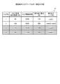
図4は、実施例1に係るジョブテーブルのデータ構造の一例を示す図である。図4に示すように、ジョブテーブル21は、ジョブID(IDentifier)、ジョブ予想実行時間、ジョブ開始時刻、割り当て電力および割り当てノードIDを対応付けて記憶する。ジョブIDは、投入されたジョブを識別する識別子である。ジョブ予想実行時間は、ジョブの開始から終了までの予想実行時間を示す。ジョブ開始時刻は、ジョブの開始時刻を示す。割り当て電力は、割り当てられる電力の値を示す。割り当てノードIDは、割り当てられるノードの識別子を示す。ジョブ開始時刻、割り当て電力および割り当てノードIDは、後述するスケジューラ部11によって定められる。ジョブ予想実行時間は、後述するスケジューラ部11によって取得されても良いし、ユーザによって指定されても良い。 FIG. 4 is a diagram illustrating an example of the data structure of a job table according to the first embodiment. As shown in FIG. 4, the job table 21 stores a job ID (IDentifier), expected job execution time, job start time, allocated power, and allocated node ID in association with each other. The job ID is an identifier that identifies the submitted job. The expected job execution time indicates the expected execution time from the start to the end of the job. The job start time indicates the start time of the job. Allocated power indicates the value of allocated power. The assigned node ID indicates the identifier of the assigned node. The job start time, allocated power, and allocated node ID are determined by the scheduler unit 11, which will be described later. The expected job execution time may be acquired by the scheduler unit 11, which will be described later, or may be specified by the user.
一例として、ジョブIDが「1」である場合に、ジョブ予想実行時間として「60」分ジョブ開始時刻として「10:00」、割り当て電力として「100」W、割り当てノードIDとして「node1」を記憶している。 As an example, when the job ID is "1", the expected job execution time is "60", the job start time is "10:00", the allocated power is "100" W, and the allocated node ID is "node1". are doing.
図3に戻って、システム電力情報22は、電力制御システム9に割り当てられた上限の電力を示す情報を含む。電力制御システム9に割り当てられた上限の電力は、電力会社との契約によって規定される。また、システム電力情報22には、システムの余剰電力が設定される。
Returning to FIG. 3, the
スケジューラ部11は、ジョブのスケジューリングを行う。例えば、スケジューラ部11は、ユーザによって指定された実行すべきジョブのジョブIDおよびノード数を受け付ける。スケジューラ部11は、受け付けたジョブIDが示すジョブの消費電力を予測する。スケジューラ部11は、受け付けたジョブIDが示すジョブの予想実行時間を取得する。ジョブの消費電力は、いかなる従来技術を用いても良い。ジョブの消費電力は、一例として、非特許文献1で挙げた技術を用いれば良い。ジョブの予想実行時間は、予めジョブごとに計測され、記憶しておけば良い。そして、スケジューラ部11は、受け付けたジョブIDごとに、ノード数、ジョブの予想実行時間、消費電力に基づいて、実行するノードおよび開始時刻を割り当てる。そして、スケジューラ部11は、ジョブIDごとに、ジョブ予想実行時間、ジョブ開始時刻、割り当て電力および割り当てノードIDをジョブテーブル21に格納する。割り当て電力は、初期値として予測された消費電力であれば良い。
The scheduler unit 11 schedules jobs. For example, the scheduler unit 11 receives the job ID of the job to be executed and the number of nodes specified by the user. The scheduler unit 11 predicts the power consumption of the job indicated by the received job ID. The scheduler unit 11 obtains the expected execution time of the job indicated by the received job ID. Any conventional technique may be used to measure the power consumption of the job. For power consumption of a job, the technique mentioned in
ジョブ実行指示部12は、ジョブの実行を計算ノード3に指示する。例えば、ジョブ実行指示部12は、ジョブテーブル21を参照し、ジョブIDが示すジョブの開始時刻になった場合に、当該ジョブを実行するノードIDが示す計算ノード3に対して、キャップ値とともに当該ジョブの実行を指示する。ここでいうキャップ値とは、ジョブの割り当て電力の値であり、指示される計算ノード3が電力キャッピングする際の消費電力の限界値のことをいう。
The job execution instruction unit 12 instructs the
電力制御部13は、複数の計算ノード3の電力を制御する。例えば、電力制御部13は、複数の計算ノード3のうちいずれかの計算ノード3から電力超過が発生した旨の通知を受信すると、ジョブテーブル21を用いて、電力超過が発生した計算ノード3が実行中のジョブのジョブIDを特定する。そして、電力制御部13は、ジョブテーブル21およびシステム電力情報22に基づいて、特定されたジョブIDが示すジョブを実行する計算ノード3にシステムの余剰電力を段階的に一定量ずつ割り当てる。そして、電力制御部13は、電力超過が発生した計算ノード3に対して、実行中のジョブの新たなキャップ値を通知する。そして、電力制御部13は、ジョブテーブル21の特定されたジョブIDに対して、新たなキャップ値を割り当て電力として更新する。また、電力制御部13は、特定されたジョブIDのジョブの実行中に、再度同じ計算ノード3から電力超過が発生した旨の通知を受信すると、システムの余剰電力が一定量より大きければ、システムの余剰電力を当該計算ノード3に一定量割り当てれば良い。なお、段階的に割り当てる電力の一定量は、例えば、「10」Wや「20」Wであるが、これに限定されず、電力制御システム9に割り当てられた上限の電力に応じて予め定められれば良い。また、一旦定められた一定量は、更新されるようにしても良い。
The power control unit 13 controls the power of the plurality of
[計算ノードの機能構成]
図5は、実施例1に係る計算ノードの機能構成を示すブロック図である。図5に示すように、計算ノード3は、電力抑制部31と、電力監視部32と、ジョブ実行部33と、電力測定部34とを有する。
[Functional configuration of calculation node]
FIG. 5 is a block diagram showing the functional configuration of a calculation node according to the first embodiment. As shown in FIG. 5, the
電力抑制部31は、消費電力を抑制する。例えば、電力抑制部31は、制御装置1からジョブの実行指示を受け付けると、実行指示に含まれるキャップ値が上限となるように消費電力を制限する。すなわち、電力抑制部31は、電力キャッピングを行う。なお、電力抑制部31は、ハードウェアであっても、ソフトウェアであっても良い。
The power suppression unit 31 suppresses power consumption. For example, upon receiving a job execution instruction from the
電力監視部32は、消費電力を監視する。例えば、電力監視部32は、後述する電力測定部34から測定される消費電力の値を監視する。電力監視部32は、消費電力の値がキャップ値の超過を検知すると、電力超過が発生した旨を制御装置1に通知する。
The power monitoring unit 32 monitors power consumption. For example, the power monitoring unit 32 monitors the value of power consumption measured by a
ジョブ実行部33は、ジョブを実行する。例えば、ジョブ実行部33は、制御装置1から実行指示があったジョブを実行する。
The job execution unit 33 executes a job. For example, the job execution unit 33 executes a job that is instructed to be executed by the
電力測定部34は、計算ノード3の消費電力を測定する。一例として、電力測定部34は、電力測定器に対応する。電力測定部34は、計算ノード3に接続すれば良い。
The
[更新後のジョブテーブルの一例]
図6は、更新後のジョブテーブルの一例を示す図である。なお、システム電力は、500Wであるとする。
[Example of updated job table]
FIG. 6 is a diagram showing an example of an updated job table. Note that the system power is assumed to be 500W.
スケジューラ部11は、ユーザによって指定された実行すべきジョブIDおよびノード数を受け付けると、ジョブIDごとに、ジョブ予想実行時間、ジョブ開始時刻、割り当て電力および割り当てノードIDをジョブテーブル21に格納する。ここでいうジョブテーブル21は、図4で示すテーブルであるとする。 Upon receiving the job ID to be executed and the number of nodes designated by the user, the scheduler unit 11 stores the expected job execution time, job start time, allocated power, and allocated node ID in the job table 21 for each job ID. The job table 21 here is assumed to be the table shown in FIG. 4.
そして、ジョブ実行指示部12は、ジョブテーブル21を参照し、ジョブID「1」のジョブの開始時刻「10:00」になったとき、当該ジョブを実行するノードID「node1」の計算ノード3に対して、当該ジョブの実行を指示する。実行指示には、ジョブID「1」とともにキャップ値「100」が含まれる。この結果、「node1」の計算ノード3では、キャップ値「100」が上限となるように、ジョブID「1」のジョブを実行する。
Then, the job execution instruction unit 12 refers to the job table 21, and when the start time of the job with the job ID "1" reaches "10:00", the job execution instruction unit 12 selects the
ここで、電力制御部13は、「node1」の計算ノード3から電力超過が発生した旨の通知を受信すると、ジョブテーブル21を用いて、電力超過が発生した計算ノード3が実行中のジョブのジョブID「1」を特定する。
Here, when the power control unit 13 receives a notification that power excess has occurred from the
そして、電力制御部13は、ジョブテーブル21およびシステム電力情報22に基づいて、特定されたジョブID「1」のジョブを実行する計算ノード3にシステムの余剰電力を段階的に一定量だけ割り当てる。
Then, based on the job table 21 and the
一例として、現在の時刻が「10:10」とする。すると、電力制御部13は、ジョブID「1」の残り時間を計算する。ここでは、ジョブID「1」のジョブ予想実行時間は「60」分であるので、残り時間は「40」分と計算される。そして、電力制御部13は、新たに割り当て可能な電力を計算する。ここでは、現在の時刻で既に割り当て済の電力は、ジョブID「1」および「2」に対応する電力を示す「300」Wである。システム電力の余剰電力は「200」Wである。かかる余剰電力は、システム電力情報22から取得されれば良い。ジョブID「1」のジョブは実行開始から10分経過しており、残り時間は50分である。ジョブID「1」の残り時間の間の「10:30」から、ジョブID「3」のジョブが「100」W使用する予定である。したがって、ジョブID「1」の残り時間の「50」分間使用できる割り当て可能な電力は、「100」Wと計算される。そして、電力制御部13は、段階的に割り当てる一定量を「10」Wとすると、「10」Wが割り当て可能な電力「100」W以内であるので、「10」Wを追加の電力量と決定する。そして、電力制御部13は、「node1」の計算ノード3に対して、新たなキャップ値「110」Wを通知する。そして、電力制御部13は、ジョブテーブル21の特定されたジョブID「1」に対して、割り当て電力を新たなキャップ値「110」に更新する。図6に示すジョブテーブル21が、電力制御部13によって更新された更新後のジョブテーブルである。この結果、「node1」の計算ノード3では、新たなキャップ値「110」が上限となるように、ジョブID「1」のジョブを実行する。すなわち、「node1」の計算ノード3は、新たなキャップ値「110」で電力キャッピングを行う。
As an example, assume that the current time is "10:10". Then, the power control unit 13 calculates the remaining time of job ID "1". Here, since the expected job execution time for job ID "1" is "60" minutes, the remaining time is calculated as "40" minutes. Then, the power control unit 13 calculates newly allocable power. Here, the power already allocated at the current time is "300" W, which indicates the power corresponding to job IDs "1" and "2". The surplus power of the system power is "200" W. Such surplus power may be obtained from the
[スケジューラの基本動作]
図7は、実施例1に係るスケジューラの基本動作のフローチャートの一例を示す図である。なお、ユーザ端末5は、ユーザによって指定された、ジョブIDおよびノード数を含むジョブの実行要求を制御装置1に対して送信したとする。
[Basic operation of scheduler]
FIG. 7 is a diagram illustrating an example of a flowchart of the basic operation of the scheduler according to the first embodiment. It is assumed that the user terminal 5 transmits to the control device 1 a job execution request that includes a job ID and the number of nodes specified by the user.
図7に示すように、スケジューラ部11は、実行すべきジョブのジョブIDを受け付ける(ステップS11)。スケジューラ部11は、ジョブIDが示すジョブの消費電力を予測する(ステップS12)。ジョブの消費電力は、いかなる従来技術を用いても良い。ジョブの消費電力は、一例として、非特許文献1で挙げた技術を用いれば良い。
As shown in FIG. 7, the scheduler unit 11 receives a job ID of a job to be executed (step S11). The scheduler unit 11 predicts the power consumption of the job indicated by the job ID (step S12). Any conventional technique may be used to measure the power consumption of the job. For power consumption of a job, the technique mentioned in
そして、スケジューラ部11は、予測電力および要求ノード数に基づいて、ジョブIDが示すジョブをスケジューリングする(ステップS13)。例えば、スケジューラ部11は、受け付けたジョブIDが示すジョブの予想実行時間を取得する。ジョブの予想実行時間は、予めジョブごとに計測され、記憶しておけば良い。そして、スケジューラ部11は、受け付けたジョブIDごとに、ノード数、ジョブの予想実行時間、消費電力に基づいて、実行するノードおよび開始時刻を割り当てる。そして、スケジューラ部11は、ジョブIDごとに、ジョブ予想実行時間、ジョブ開始時刻、割り当て電力(予測電力)および割り当てノードIDを含むジョブテーブル21を作成する。 Then, the scheduler unit 11 schedules the job indicated by the job ID based on the predicted power and the number of requested nodes (step S13). For example, the scheduler unit 11 obtains the expected execution time of the job indicated by the received job ID. The expected execution time of a job may be measured and stored in advance for each job. Then, the scheduler unit 11 allocates a node for execution and a start time for each received job ID based on the number of nodes, expected execution time of the job, and power consumption. The scheduler unit 11 then creates a job table 21 that includes the expected job execution time, job start time, allocated power (predicted power), and allocated node ID for each job ID.
そして、スケジューラ部11は、ジョブの開始時刻が到来したら、この時点での予測電力を割り当て電力として、システム電力情報22のシステム電力から差し引く(ステップS14)。そして、ジョブ実行指示部12は、開始時刻が到来したジョブを実行する計算ノード3に対して、キャップ値を割り当て電力とした当該ジョブの実行を指示して、当該ジョブを実行させる(ステップS15)。
Then, when the job start time arrives, the scheduler unit 11 subtracts the predicted power at this time from the system power in the
スケジューラ部11は、ジョブが終了するのを検知すると(ステップS16)、システム電力情報22のシステム電力に割り当て電力を加算して、割り当て済みの電力をシステムに戻す(ステップS17)。
When the scheduler unit 11 detects that the job ends (step S16), it adds the allocated power to the system power in the
[電力制御の動作]
図8は、実施例1に係る電力制御のフローチャートの一例を示す図である。
[Power control operation]
FIG. 8 is a diagram illustrating an example of a flowchart of power control according to the first embodiment.
電力制御部13は、電力超過が発生した旨の通知を受信したか否かを判定する(ステップS21)。電力超過が発生した旨の通知を受信していないと判定した場合には(ステップS21;No)、電力制御部13は、受信するまで、判定処理を繰り返す。 The power control unit 13 determines whether or not a notification to the effect that power exceedance has occurred is received (step S21). If it is determined that the notification that the power excess has occurred has not been received (step S21; No), the power control unit 13 repeats the determination process until the notification is received.
一方、電力超過が発生した旨の通知を受信したと判定した場合には(ステップS21;Yes)、電力制御部13は、以下の処理を行う。電力制御部13は、ジョブテーブル21を参照して、電力超過が発生した計算ノード3のノードIDから、当該計算ノード3に割り当てられたジョブのジョブIDを特定する(ステップS22)。
On the other hand, if it is determined that a notification to the effect that power excess has occurred (step S21; Yes), the power control unit 13 performs the following processing. The power control unit 13 refers to the job table 21 and identifies the job ID of the job assigned to the
そして、電力制御部13は、特定したジョブIDが示すジョブの残り時間を取得する(ステップS23)。例えば、電力制御部13は、ジョブテーブル21を参照して、特定したジョブIDに対応するジョブ開始時刻およびジョブ予想実行時間を取得し、取得したジョブ開始時刻およびジョブ予想実行時間、現在の時刻を用いて、ジョブの残り時間を計算する。 Then, the power control unit 13 acquires the remaining time of the job indicated by the specified job ID (step S23). For example, the power control unit 13 refers to the job table 21, obtains the job start time and expected job execution time corresponding to the specified job ID, and stores the obtained job start time, expected job execution time, and current time. to calculate the remaining time for the job.
そして、電力制御部13は、割り当て可能な電力を取得する(ステップS24)。例えば、電力制御部13は、現在の時刻で、システム電力情報22からシステムの余剰電力を取得する。電力制御部13は、システムの余剰電力およびジョブの残り時間に使用予定の他のジョブの電力を用いて、割り当て可能な電力を計算する。
Then, the power control unit 13 acquires the allocatable power (step S24). For example, the power control unit 13 obtains the surplus power of the system from the
そして、電力制御部13は、追加で割り当てる電力を計算する(ステップS25)。例えば、電力制御部13は、割り当て可能な電力のうち一定量を割り当て電力として計算する。 Then, the power control unit 13 calculates the additional power to be allocated (step S25). For example, the power control unit 13 calculates a certain amount of allocable power as the allocated power.
そして、電力制御部13は、割り当て電力が0より大きいか否かを判定する(ステップS26)。割り当て電力が0以下であると判定した場合には(ステップS26;No)、電力制御部13は、追加で割り当てができないので、電力制御処理を終了する。 Then, the power control unit 13 determines whether the allocated power is greater than 0 (step S26). If it is determined that the allocated power is 0 or less (step S26; No), the power control unit 13 ends the power control process because no additional allocation can be made.
一方、割り当て電力が0より大きいと判定した場合には(ステップS26;Yes)、電力制御部13は、システム電力情報22のシステムの余剰電力から割り当て電力を減算する(ステップS27)。 On the other hand, if it is determined that the allocated power is greater than 0 (step S26; Yes), the power control unit 13 subtracts the allocated power from the system surplus power in the system power information 22 (step S27).
そして、電力制御部13は、特定したジョブの実行中に電力超過が発生した計算ノード3に新たなキャップ値を通知する(ステップS28)。新たなキャップ値は、既に割り当てられている割り当て電力に追加の割り当て電力を加算した電力の値を示す。そして、電力制御部13は、ジョブテーブル21の特定したジョブに対して、割り当て電力を新たなキャップ値に更新する。そして、電力制御部13は、電力制御処理を終了する。
Then, the power control unit 13 notifies the
[実施例1の効果]
上記実施例1によれば、電力制御システム9は、複数の計算ノード3と制御装置1とを備える。制御装置1は、ジョブごとに、計算ノード3で実行する際の使用可能な割り当て電力の値を記憶するジョブテーブル21を有する。制御装置1は、電力制御システム9の余剰電力を管理する。制御装置1は、複数の計算ノード3のうちいずれかの計算ノード3の消費電力の値が割り当て電力の値を超過する場合に、ジョブテーブル21に記憶された情報から当該計算ノード3が実行中のジョブを特定する。制御装置1は、ジョブテーブル21に記憶された情報および電力制御システム9の余剰電力に基づいて、特定されたジョブを実行する計算ノード3に余剰電力を段階的に割り当てる。かかる構成によれば、制御装置1は、消費電力が割り当て電力を超過した場合に、余剰電力を段階的に割り当てることで、他のジョブを実行する計算ノード3に対して割り当てる余剰電力を確保することが可能となる。加えて、制御装置1は、余剰電力を割り当てた計算ノード3のジョブの実行性能低下を抑制することが可能となる。
[Effects of Example 1]
According to the first embodiment, the
また、上記実施例1によれば、制御装置1は、余剰電力のうち予め設定された割り当て電力を段階的に割り当てる。かかる構成によれば、制御装置1は、余剰電力のうち予め設定された割り当て電力を段階的に割り当てることで、他のジョブを実行する計算ノード3に対して割り当てる余剰電力を確保することができる。
Further, according to the first embodiment, the
また、上記実施例1によれば、ジョブテーブル21は、ジョブごとに、実行する計算ノード3、予想実行時間、実行開始時刻および使用可能な割り当て電力の値を対応付けて記憶する。制御装置1は、特定されたジョブの残り時間、他のジョブの実行開始時刻および使用可能な割り当て電力並びに電力制御システム9の余剰電力に基づいて、特定されたジョブを実行する計算ノード3に余剰電力を段階的に割り当てる。かかる構成によれば、制御装置1は、確実に、他のジョブを実行する計算ノード3に対して割り当てる余剰電力を確保することができる。
Further, according to the first embodiment, the job table 21 stores, for each job, the
ところで、実施例1では、制御装置1が、ジョブを実行する計算ノード3から電力超過が発生した旨の通知を受信すると、計算ノード3にシステムの余剰電力を段階的に一定量ずつ割り当てると説明した。すなわち、制御装置1は、ジョブを実行する計算ノード3から電力超過が発生した旨の通知を受信すると、追加の割り当て電力を固定とする。しかしながら、制御装置1は、これに限定されず、ジョブを実行する計算ノード3から過去に電力超過が発生したことがある場合には、過去に電力超過した超過量をベースに、新たな追加の割り当て電力を動的に変更しても良い。
By the way, in the first embodiment, when the
そこで、制御装置1は、ジョブを実行する計算ノード3から過去に電力超過が発生したことがある場合には、過去に電力超過した超過量をベースに、新たな追加の割り当て電力を動的に変更する場合を説明する。
Therefore, if a power excess has occurred in the past from the
[制御装置の機能構成]
図9は、実施例2に係る制御装置の機能構成を示すブロック図である。なお、図2に示す制御装置1と同一の構成については同一符号を示すことで、その重複する構成および動作の説明については省略する。実施例1と実施例2とが異なるところは、制御部10のスケジューラ部11および電力制御部13をそれぞれスケジューラ部11Aおよび電力制御部13Aに変更した点にある。また、実施例1と実施例2とが異なるところは、記憶部20に電力履歴情報23Aを追加した点にある。
[Functional configuration of control device]
FIG. 9 is a block diagram showing the functional configuration of the control device according to the second embodiment. Note that the same components as those of the
電力履歴情報23Aは、電力超過が発生したジョブごとに、追加で割り当てされた最終の割り当て電力を履歴として記憶した情報である。
The
スケジューラ部11Aは、ジョブのスケジューリングを行う。 The scheduler unit 11A schedules jobs.
例えば、スケジューラ部11Aは、ユーザによって指定された実行すべきジョブのジョブIDおよびノード数を受け付ける。スケジューラ部11Aは、受け付けたジョブIDが示すジョブの消費電力を予測する。一例として、スケジューラ部11Aは、ジョブIDが示すジョブが過去に電力超過が発生した場合には、前回の最終の割り当て電力を予測値とする。スケジューラ部11Aは、過去に電力超過が発生していない場合には、予測した消費電力を予測値とする。ジョブの消費電力は、いかなる従来技術を用いても良い。 For example, the scheduler unit 11A receives the job ID and number of nodes of the job to be executed specified by the user. The scheduler unit 11A predicts the power consumption of the job indicated by the received job ID. As an example, if the job indicated by the job ID has experienced excess power in the past, the scheduler unit 11A uses the last final allocated power as the predicted value. The scheduler unit 11A sets the predicted power consumption as a predicted value if power excess has not occurred in the past. Any conventional technique may be used to measure the power consumption of the job.
また、スケジューラ部11Aは、受け付けたジョブIDが示すジョブの予想実行時間を取得する。そして、スケジューラ部11Aは、受け付けたジョブIDごとに、ノード数、ジョブ予想実行時間、消費電力に基づいて、実行するノードおよび開始時刻を割り当てる。そして、スケジューラ部11Aは、ジョブIDごとに、ジョブ予想実行時間、ジョブ開始時刻、割り当て電力および割り当てノードIDをジョブテーブル21に格納する。割り当て電力は、初期値として予測された消費電力であれば良い。 The scheduler unit 11A also obtains the expected execution time of the job indicated by the received job ID. The scheduler unit 11A then assigns a node to execute and a start time for each received job ID based on the number of nodes, expected job execution time, and power consumption. The scheduler unit 11A then stores the expected job execution time, job start time, allocated power, and allocated node ID in the job table 21 for each job ID. The allocated power may be the power consumption predicted as an initial value.
また、スケジューラ部11Aは、割り当て電力を超過したジョブに対して、超過量および超過量を追加した最終の割り当て電力の値を電力履歴情報23Aに記録する。
Furthermore, the scheduler unit 11A records the excess amount and the final allocated power value to which the excess amount has been added, in the
電力制御部13Aは、複数の計算ノード3の電力を制御する。例えば、電力制御部13Aは、複数の計算ノード3のうちいずれかの計算ノード3から電力超過が発生した旨の通知を受信すると、ジョブテーブル21を用いて、電力超過が発生した計算ノード3が実行中のジョブのジョブIDを特定する。そして、電力制御部13Aは、電力履歴情報23Aを参照して、ジョブIDが示すジョブが過去に電力超過が発生したか否かを判定する。電力制御部13Aは、ジョブIDが示すジョブが過去に電力超過が発生した場合には、システムの余剰電力が前回の超過量より大きければ、当該ジョブを実行する計算ノード3に前回の超過量を追加で割り当てる。そして、電力制御部13Aは、計算ノード3に対して、実行中のジョブの新たなキャップ値を通知する。そして、電力制御部13Aは、ジョブテーブル21の特定されたジョブIDに対して、割り当て電力を新たなキャップ値に更新する。また、電力制御部13Aは、特定されたジョブIDのジョブの実行中に、再度同じ計算ノード3から電力超過が発生した旨の通知を受信すると、さらに前回の超過量を追加して割り当てれば良い。
The power control unit 13A controls the power of the plurality of
なお、電力制御部13Aは、ジョブIDが示すジョブが過去に電力超過が発生していない場合には、当該ジョブを実行する計算ノード3に余剰電力を段階的に一定量ずつ割り当てれば良い。
Note that if the job indicated by the job ID has not experienced excess power in the past, the power control unit 13A may allocate a fixed amount of surplus power in stages to the
[実施例2に係る電力割り当て]
図10は、実施例2に係る電力割り当てを説明する図である。図10上段に示すように、ジョブXは、n-1回目の投入時まで、過去に電力超過が発生していなかったとする。スケジューラ部11Aは、ジョブXのn回目の投入時に、ジョブXの消費電力を「40」Wと予測する。ジョブ実行指示部12は、キャップ値「40」Wとともにジョブの実行を指示する。電力制御部13Aは、ジョブXを実行する計算ノード3から電力超過が発生した旨の通知を受信すると、過去に電力超過が発生していないので、一定量の「10」Wを追加割り当てする。ジョブXは、2回の追加割り当てがあったので、最終の割り当て電力量は「60」Wを示す。そこで、スケジューラ部11Aは、割り当て電力を超過したジョブXに対して、超過量「20」Wおよび最終の割り当て電力の値「60」Wを電力履歴情報23Aに記録する。
[Power allocation according to Example 2]
FIG. 10 is a diagram illustrating power allocation according to the second embodiment. As shown in the upper part of FIG. 10, it is assumed that job The scheduler unit 11A predicts the power consumption of job X to be "40" W when job X is submitted for the nth time. The job execution instruction unit 12 instructs execution of the job along with the cap value "40" W. When the power control unit 13A receives a notification that a power excess has occurred from the
そして、スケジューラ部11Aは、ジョブXのn+1回目の投入時の消費電力を前回の割り当て電力の値の「60」Wと予測する。そして、このジョブXは、実行終了まで「60」Wを超過しないで実行する。 Then, the scheduler unit 11A predicts that the power consumption when the job X is submitted for the (n+1) time will be "60" W, which is the value of the previous allocated power. Then, this job X is executed without exceeding "60" W until the end of execution.
図10下段に示すように、ジョブZは、n-1回目の投入時まで、過去に電力超過が発生していなかったとする。スケジューラ部11Aは、ジョブZのn回目の投入時に、ジョブZの消費電力を「40」Wと予測する。ジョブ実行指示部12は、キャップ値「40」Wとともにジョブの実行を指示する。電力制御部13Aは、ジョブZを実行する計算ノード3から電力超過が発生した旨の通知を受信すると、過去に電力超過が発生していないので、一定量の「10」Wを追加割り当てする。ジョブXは、2回の追加割り当てがあったので、最終の去り当て電力量は「60」Wを示す。そこで、スケジューラ部11Aは、割り当て電力を超過したジョブXに対して、超過量「20」Wおよび最終の割り当て電力の値「60」Wを電力履歴情報23Aに記録する。
As shown in the lower part of FIG. 10, it is assumed that job Z has not experienced an excess power in the past until the (n-1)th input. The scheduler unit 11A predicts the power consumption of job Z to be "40" W when job Z is submitted for the nth time. The job execution instruction unit 12 instructs execution of the job along with the cap value "40" W. When the power control unit 13A receives a notification that a power excess has occurred from the
そして、スケジューラ部11Aは、ジョブZのn+1回目の投入時の消費電力を前回の割り当て電力の「60」Wと予測する。そして、電力制御部13Aは、ジョブZを実行する計算ノード3から電力超過が発生した旨の通知を受信すると、前回の超過量「20」Wを追加割り当てする。
Then, the scheduler unit 11A predicts that the power consumption when the job Z is submitted for the (n+1) time will be "60" W, which is the previously allocated power. Then, when the power control unit 13A receives a notification from the
これにより、電力制御部13Aは、例えば電力変動が大きいジョブの場合には、過去に与えた超過量を利用して動的に追加割り当てをすることで、ジョブの特性に応じた電力割当を行うことが可能となる。また、電力制御部13Aは、余剰電力を全て電力割当する場合と比較して、他のノードが消費電力の上限を超えたときに対応することができる。 As a result, for example, in the case of a job with large power fluctuations, the power control unit 13A dynamically allocates additional power using the excess amount given in the past, thereby allocating power according to the characteristics of the job. becomes possible. Moreover, the power control unit 13A can respond when another node exceeds the upper limit of power consumption, compared to a case where all surplus power is allocated.
[スケジューラの基本動作]
図11は、実施例2に係るスケジューラの基本動作のフローチャートの一例を示す図である。なお、ユーザ端末5は、ユーザによって指定された、ジョブIDおよびノード数を含むジョブの実行要求を制御装置1に対して送信したとする。
[Basic operation of scheduler]
FIG. 11 is a diagram illustrating an example of a flowchart of the basic operation of the scheduler according to the second embodiment. It is assumed that the user terminal 5 transmits to the control device 1 a job execution request that includes a job ID and the number of nodes specified by the user.
図11に示すように、スケジューラ部11Aは、実行すべきジョブのジョブIDを受け付ける(ステップS31)。スケジューラ部11Aは、ジョブIDが示すジョブの消費電力を予測する(ステップS32)。 As shown in FIG. 11, the scheduler unit 11A receives a job ID of a job to be executed (step S31). The scheduler unit 11A predicts the power consumption of the job indicated by the job ID (step S32).
スケジューラ部11Aは、過去に電力超過の記録があるか否かを判定する(ステップS32A)。例えば、スケジューラ部11Aは、電力履歴情報23Aを参照して、ジョブIDが示すジョブの電力超過が発生した履歴があるか否かを判定する。過去に電力超過の記録がないと判定した場合には(ステップS32A;No)、スケジューラ部11Aは、ステップS33に移行する。
The scheduler unit 11A determines whether there is a record of excess power in the past (step S32A). For example, the scheduler unit 11A refers to the
一方、過去に電力超過の記録があると判定した場合には(ステップS32A;Yes)、スケジューラ部11Aは、前回の割り当て電力を予測電力とする(ステップS32B)。例えば、スケジューラ部11Aは、電力履歴情報23AのジョブIDに対応する割り当て電力を取得して、予測電力とする。そして、スケジューラ部11Aは、ステップS33に移行する。
On the other hand, if it is determined that there is a record of excess power in the past (step S32A; Yes), the scheduler unit 11A sets the previously allocated power as the predicted power (step S32B). For example, the scheduler unit 11A obtains the allocated power corresponding to the job ID of the
ステップS33において、スケジューラ部11Aは、予測電力および要求ノード数に基づいて、ジョブIDが示すジョブをスケジューリングする(ステップS33)。そして、スケジューラ部11Aは、ジョブIDごとに、ジョブ予想実行時間、ジョブ開始時刻、割り当て電力(予測電力)および割り当てノードIDを含むジョブテーブル21を作成する。 In step S33, the scheduler unit 11A schedules the job indicated by the job ID based on the predicted power and the number of requested nodes (step S33). The scheduler unit 11A then creates a job table 21 that includes the expected job execution time, job start time, allocated power (predicted power), and allocated node ID for each job ID.
そして、スケジューラ部11Aは、ジョブの開始時刻が到来したら、この時点での予測電力を割り当て電力として、システム電力情報22のシステム電力から差し引く(ステップS34)。そして、ジョブ実行指示部12は、開始時刻が到来したジョブを実行する計算ノード3に対して、キャップ値を割り当て電力とした当該ジョブの実行を指示して、当該ジョブを実行させる(ステップS35)。
Then, when the job start time arrives, the scheduler unit 11A subtracts the predicted power at this time from the system power in the
スケジューラ部11Aは、ジョブが終了するのを検知すると(ステップS36)、超過割り当て量を記録する(ステップS37)。例えば、スケジューラ部11Aは、割り当て電力を超過したジョブに対して、超過量および超過量を追加した最終の割り当て電力の値を電力履歴情報23Aに記録する。
When the scheduler unit 11A detects that the job ends (step S36), it records the excess allocation amount (step S37). For example, the scheduler unit 11A records the excess amount and the final allocated power value to which the excess amount has been added, in the
そして、スケジューラ部11は、システム電力情報22のシステム電力に割り当て電力を加算して、割り当て済みの電力をシステムに戻す(ステップS38)。
Then, the scheduler unit 11 adds the allocated power to the system power in the
[電力制御の動作]
図12は、実施例2に係る電力制御のフローチャートの一例を示す図である。
[Power control operation]
FIG. 12 is a diagram illustrating an example of a flowchart of power control according to the second embodiment.
電力制御部13Aは、電力超過が発生した旨の通知を受信したか否かを判定する(ステップS41)。電力超過が発生した旨の通知を受信していないと判定した場合には(ステップS41;No)、電力制御部13Aは、受信するまで、判定処理を繰り返す。 The power control unit 13A determines whether or not a notification to the effect that power excess has occurred has been received (step S41). If it is determined that the notification that the power excess has occurred has not been received (step S41; No), the power control unit 13A repeats the determination process until the notification is received.
一方、電力超過が発生した旨の通知を受信したと判定した場合には(ステップS41;Yes)、電力制御部13Aは、以下の処理を行う。電力制御部13Aは、ジョブテーブル21を参照して、電力超過が発生した計算ノード3のノードIDから、当該計算ノード3に割り当てられたジョブのジョブIDを特定する(ステップS42)。
On the other hand, if it is determined that a notification to the effect that power exceedance has occurred (step S41; Yes), the power control unit 13A performs the following processing. The power control unit 13A refers to the job table 21 and identifies the job ID of the job assigned to the
そして、電力制御部13Aは、特定したジョブIDが示すジョブの残り時間を取得する(ステップS43)。例えば、電力制御部13Aは、ジョブテーブル21を参照して、特定したジョブIDに対応するジョブ開始時刻およびジョブ予想実行時間を取得する。電力制御部13Aは、取得したジョブ開始時刻およびジョブ予想実行時間、現在の時刻を用いて、ジョブの残り時間を計算する。 Then, the power control unit 13A obtains the remaining time of the job indicated by the specified job ID (step S43). For example, the power control unit 13A refers to the job table 21 and obtains the job start time and job expected execution time corresponding to the specified job ID. The power control unit 13A calculates the remaining time of the job using the acquired job start time, expected job execution time, and current time.
そして、電力制御部13Aは、割り当て可能な電力を取得する(ステップS44)。例えば、電力制御部13Aは、現在の時刻で、システム電力情報22からシステムの余剰電力を取得する。電力制御部13Aは、システムの余剰電力およびジョブの残り時間に使用予定の他のジョブの電力を用いて、割り当て可能な電力を計算する。
Then, the power control unit 13A obtains the allocatable power (step S44). For example, the power control unit 13A obtains the system surplus power from the
そして、電力制御部13Aは、特定したジョブIDについて、過去に超過記録があるか否かを判定する(ステップS45)。例えば、電力制御部13Aは、電力履歴情報23Aを参照して、ジョブIDが示すジョブが過去に電力超過が発生したか否かを判定する。過去に超過記録があると判定した場合には(ステップS45;Yes)、電力制御部13Aは、割り当て電力を計算する(ステップS47)。例えば、電力制御部13Aは、ジョブIDが示すジョブを実行する計算ノード3に前回の超過量を追加の割り当て電力として計算する。そして、電力制御部13Aは、ステップS48に移行する。
Then, the power control unit 13A determines whether there is a record of excess power in the past for the specified job ID (step S45). For example, the power control unit 13A refers to the
一方、過去に超過記録がないと判定した場合には(ステップS45;No)、電力制御部13Aは、固定の割り当て電力を追加の割り当て電力として計算する(ステップS46)。例えば、電力制御部13Aは、割り当て可能な電力のうち一定量を割り当て電力として計算する。そして、電力制御部13Aは、ステップS48に移行する。 On the other hand, if it is determined that there is no record of excess in the past (step S45; No), the power control unit 13A calculates the fixed allocated power as additional allocated power (step S46). For example, the power control unit 13A calculates a certain amount of allocable power as the allocated power. The power control unit 13A then proceeds to step S48.
そして、電力制御部13Aは、割り当て電力が0より大きいか否かを判定する(ステップS48)。割り当て電力が0以下であると判定した場合には(ステップS48;No)、追加で割り当てできないので、電力制御部13Aは、電力制御処理を終了する。 Then, the power control unit 13A determines whether the allocated power is greater than 0 (step S48). If it is determined that the allocated power is less than or equal to 0 (step S48; No), the power control unit 13A ends the power control process because additional allocation is not possible.
一方、割り当て電力が0より大きいと判定した場合には(ステップS48;Yes)、電力制御部13Aは、システム電力情報22のシステムの余剰電力から割り当て電力を減算する(ステップS49)。 On the other hand, if it is determined that the allocated power is greater than 0 (step S48; Yes), the power control unit 13A subtracts the allocated power from the system surplus power in the system power information 22 (step S49).
そして、電力制御部13Aは、特定したジョブの実行中に電力超過が発生した計算ノード3に新たなキャップ値を通知する(ステップS50)。新たなキャップ値は、既に割り当てられている割り当て電力に追加の割り当て電力を加算した電力の値を示す。そして、電力制御部13Aは、ジョブテーブル21の特定したジョブに対して、割り当て電力を新たなキャップ値に更新する。そして、電力制御部13Aは、電力制御処理を終了する。
Then, the power control unit 13A notifies the
なお、電力制御部13Aは、電力超過が発生したジョブについて、過去に電力超過が発生していた場合には、当該ジョブを実行する計算ノード3に前回の超過量と同じだけの電力を追加で割り当てる説明した。しかしながら、電力制御部13Aは、これに限定されず、前回の超過量の1/2や1/3の電力を追加で割り当てても良い。
Note that the power control unit 13A can add the same amount of power as the previous excess amount to the
[実施例2の効果]
上記実施例2によれば、制御装置1は、消費電力の値が割り当て電力の値を超過した計算ノード3で実行中のジョブが過去に割り当て電力を超過した場合には、超過した値に基づいて新たに割り当てる値を計算する。制御装置1は、計算した値分余剰電力を段階的に割り当てる。かかる構成によれば、制御装置1は、過去の超過した値を用いて割り当てる値を計算することで、ジョブの特性に応じた電力割当を行うことが可能となる。また、制御装置1は、余剰電力を全て電力割当する場合と比較して、他の計算ノード3が消費電力の上限を超えたときに対応することができる。
[Effects of Example 2]
According to the second embodiment, if the job being executed on the
[その他]
なお、実施例1,2では、電力制御部13,13Aが、ジョブの消費電力が上限となるように電力を追加で割り当てる場合を説明した。しかしながら、電力制御部13,13Aは、これに限定されず、ジョブの消費電力が追加で割り当てた電力を下回った場合には、追加で割り当てた電力をシステム電力に変換しても良い。
[others]
In the first and second embodiments, a case has been described in which the power control units 13 and 13A allocate additional power so that the power consumption of the job becomes the upper limit. However, the power control units 13 and 13A are not limited to this, and when the power consumption of the job is less than the additionally allocated power, the power controllers 13 and 13A may convert the additionally allocated power into system power.
また、図示した制御装置1の各構成要素は、必ずしも物理的に図示の如く構成されていることを要しない。すなわち、制御装置1の分散・統合の具体的態様は図示のものに限られず、その全部または一部を、各種の負荷や使用状況などに応じて、任意の単位で機能的または物理的に分散・統合して構成することができる。例えば、スケジューラ部11とジョブ実行指示部12とを1つの部として統合しても良い。また、電力制御部13を、電力超過のジョブを特定する特定部と、特定したジョブを実行する計算ノード3に電力を割り当てる割当部とに分離しても良い。また、記憶部20を制御装置1の外部装置としてネットワーク経由で接続するようにしても良い。
Further, each component of the illustrated
また、上記実施例で説明した各種の処理は、予め用意されたプログラムをパーソナルコンピュータやワークステーションなどのコンピュータで実行することによって実現することができる。そこで、以下では、図2に示した制御装置1と同様の機能を実現する電力制御プログラムを実行するコンピュータの一例を説明する。図13は、電力制御プログラムを実行するコンピュータの一例を示す図である。
Moreover, the various processes described in the above embodiments can be realized by executing a program prepared in advance on a computer such as a personal computer or a workstation. Therefore, an example of a computer that executes a power control program that implements the same functions as the
図13に示すように、コンピュータ200は、各種演算処理を実行するCPU203と、ユーザからのデータの入力を受け付ける入力装置215と、表示装置209を制御する表示制御部207とを有する。また、コンピュータ200は、記憶媒体からプログラムなどを読取るドライブ装置213と、ネットワークを介して他のコンピュータとの間でデータの授受を行う通信制御部217とを有する。また、コンピュータ200は、各種情報を一時記憶するメモリ201と、HDD(Hard Disk Drive)205を有する。そして、メモリ201、CPU203、HDD205、表示制御部207、ドライブ装置213、入力装置215、通信制御部217は、バス219で接続されている。
As shown in FIG. 13, the
ドライブ装置213は、例えばリムーバブルディスク210用の装置である。HDD205は、電力制御プログラム205aおよび電力制御処理関連情報205bを記憶する。
The
CPU203は、電力制御プログラム205aを読み出して、メモリ201に展開し、プロセスとして実行する。かかるプロセスは、制御装置1の各機能部に対応する。電力制御処理関連情報205bは、ジョブテーブル21、システム電力情報22に対応する。そして、例えばリムーバブルディスク210が、電力制御プログラム205aなどの各情報を記憶する。
The
なお、電力制御プログラム205aについては、必ずしも最初からHDD205に記憶させておかなくても良い。例えば、コンピュータ200に挿入されるフレキシブルディスク(FD)、CD-ROM(Compact Disk Read Only Memory)、DVD(Digital Versatile Disk)、光磁気ディスク、IC(Integrated Circuit)カードなどの「可搬用の物理媒体」に当該プログラムを記憶させておく。そして、コンピュータ200がこれらから電力制御プログラム205aを読み出して実行するようにしても良い。
Note that the
1 制御装置
10 制御部
11,11A スケジューラ部
12 ジョブ実行指示部
13,13A 電力制御部
20 記憶部
21 ジョブテーブル
22 システム電力情報
23A 電力履歴情報
3 計算ノード
31 電力抑制部
32 電力監視部
33 ジョブ実行部
34 電力測定部
5 ユーザ端末
7 ネットワーク
9 電力制御システム
1
Claims (5)
ジョブごとに、前記情報処理装置で実行する際の使用可能な割り当て電力の値を記憶する記憶部と、
前記複数の情報処理装置のうちいずれかの情報処理装置の消費電力の値が割り当て電力の値を超過する場合に、前記記憶部に記憶された情報から当該情報処理装置が実行中のジョブを特定する特定部と、
前記記憶部に記憶された情報および前記電力制御システムの余剰電力に基づいて、特定されたジョブを実行する情報処理装置に余剰電力を段階的に割り当てる割当部と、
を有することを特徴とする電力制御装置。 a management unit that manages surplus power of a power control system including a plurality of information processing devices and a power control device;
a storage unit that stores, for each job, a value of usable allocated power when executed by the information processing device;
When the power consumption value of any one of the plurality of information processing devices exceeds the allocated power value, identifying a job being executed by the information processing device from information stored in the storage unit. A specific part to
an allocation unit that allocates surplus power in stages to an information processing device that executes a specified job based on information stored in the storage unit and surplus power of the power control system;
A power control device comprising:
ことを特徴とする請求項1に記載の電力制御装置。 The power control device according to claim 1, wherein the allocation unit allocates preset allocated power out of the surplus power in stages.
前記割当部は、特定されたジョブの残り時間、他のジョブの実行開始時刻および使用可能な割り当て電力並びに前記電力制御システムの余剰電力に基づいて、特定されたジョブを実行する情報処理装置に余剰電力を段階的に割り当てる
ことを特徴とする請求項1に記載の電力制御装置。 The storage unit stores, for each job, an information processing device to be executed, an expected execution time, an execution start time, and a value of available allocated power in association with each other;
The allocation unit is configured to allocate surplus power to the information processing device that executes the specified job based on the remaining time of the specified job, the execution start time of other jobs, available allocated power, and surplus power of the power control system. The power control device according to claim 1, wherein power is allocated in stages.
ことを特徴とする請求項3に記載の電力制御装置。 The allocation unit is characterized in that, when the identified job exceeds the allocated power in the past, a new value to be allocated is calculated based on the exceeded value, and the surplus power is allocated in stages by the calculated value. The power control device according to claim 3.
前記複数の情報処理装置のうちいずれかの情報処理装置の消費電力の値が割り当て電力の値を超過する場合に、ジョブごとに、情報処理装置で実行する際の使用可能な割り当て電力の値を記憶する記憶部に記憶された情報から当該情報処理装置が実行中のジョブを特定し、
前記記憶部に記憶された情報および前記電力制御システムの余剰電力に基づいて、特定されたジョブを実行する情報処理装置に余剰電力を段階的に割り当てる
ことをコンピュータに実行させることを特徴とする電力制御プログラム。 Manages surplus power in a power control system that includes multiple information processing devices and power control devices,
If the power consumption value of any of the information processing devices among the plurality of information processing devices exceeds the allocated power value, for each job, the available allocated power value when executed by the information processing device is determined. Identifying the job being executed by the information processing device from the information stored in the storage unit,
A power supply system that causes a computer to allocate surplus power in stages to an information processing device that executes a specified job based on information stored in the storage unit and surplus power of the power control system. control program.
Priority Applications (1)
| Application Number | Priority Date | Filing Date | Title |
|---|---|---|---|
| JP2020035669A JP7367565B2 (en) | 2020-03-03 | 2020-03-03 | Power control device and power control program |
Applications Claiming Priority (1)
| Application Number | Priority Date | Filing Date | Title |
|---|---|---|---|
| JP2020035669A JP7367565B2 (en) | 2020-03-03 | 2020-03-03 | Power control device and power control program |
Publications (2)
| Publication Number | Publication Date |
|---|---|
| JP2021141657A JP2021141657A (en) | 2021-09-16 |
| JP7367565B2 true JP7367565B2 (en) | 2023-10-24 |
Family
ID=77669731
Family Applications (1)
| Application Number | Title | Priority Date | Filing Date |
|---|---|---|---|
| JP2020035669A Active JP7367565B2 (en) | 2020-03-03 | 2020-03-03 | Power control device and power control program |
Country Status (1)
| Country | Link |
|---|---|
| JP (1) | JP7367565B2 (en) |
Citations (4)
| Publication number | Priority date | Publication date | Assignee | Title |
|---|---|---|---|---|
| JP2008242614A (en) | 2007-03-26 | 2008-10-09 | Nec Corp | Job scheduling apparatus and job scheduling method |
| JP2010191595A (en) | 2009-02-17 | 2010-09-02 | Nec Corp | Power distribution system and method |
| JP2017530449A (en) | 2014-08-22 | 2017-10-12 | インテル コーポレイション | Method and apparatus for managing jobs that can and cannot be interrupted when there is a change in power allocation to a distributed computer system |
| JP2019003281A (en) | 2017-06-12 | 2019-01-10 | 富士通株式会社 | System management device in parallel processing system, parallel processing system, and power control method |
-
2020
- 2020-03-03 JP JP2020035669A patent/JP7367565B2/en active Active
Patent Citations (4)
| Publication number | Priority date | Publication date | Assignee | Title |
|---|---|---|---|---|
| JP2008242614A (en) | 2007-03-26 | 2008-10-09 | Nec Corp | Job scheduling apparatus and job scheduling method |
| JP2010191595A (en) | 2009-02-17 | 2010-09-02 | Nec Corp | Power distribution system and method |
| JP2017530449A (en) | 2014-08-22 | 2017-10-12 | インテル コーポレイション | Method and apparatus for managing jobs that can and cannot be interrupted when there is a change in power allocation to a distributed computer system |
| JP2019003281A (en) | 2017-06-12 | 2019-01-10 | 富士通株式会社 | System management device in parallel processing system, parallel processing system, and power control method |
Also Published As
| Publication number | Publication date |
|---|---|
| JP2021141657A (en) | 2021-09-16 |
Similar Documents
| Publication | Publication Date | Title |
|---|---|---|
| JP5332065B2 (en) | Cluster configuration management method, management apparatus, and program | |
| JP6881575B2 (en) | Resource allocation systems, management equipment, methods and programs | |
| US9396027B2 (en) | Resource allocation for a plurality of resources for a dual activity system | |
| CN114745278B (en) | Method and device for expanding and shrinking capacity of service system, electronic equipment and storage medium | |
| US10069757B1 (en) | Reserved network device capacity | |
| JP2005534116A (en) | A method for dynamically allocating and managing resources in a multi-consumer computer system. | |
| US11074111B2 (en) | Quality of service scheduling with workload profiles | |
| CN113760549B (en) | Pod deployment method and device | |
| CN111625339A (en) | Cluster resource scheduling method, device, medium and computing equipment | |
| CN111798113A (en) | Resource allocation method, device, storage medium and electronic device | |
| CN111143063A (en) | Task resource reservation method and device | |
| US10643193B2 (en) | Dynamic workload capping | |
| WO2011138854A1 (en) | Resource management system, resource management method and resource management program | |
| JP7367565B2 (en) | Power control device and power control program | |
| JP7790147B2 (en) | Cost management device, cost management method, and program | |
| KR20070041462A (en) | Grid resource management system based on effective resource quorum generation module and method | |
| JP6191361B2 (en) | Information processing system, information processing system control method, and control program | |
| JP6094272B2 (en) | Management system, management method, management program, and management apparatus | |
| JP2019046163A (en) | INFORMATION PROCESSING APPARATUS, VIRTUAL MACHINE MONITORING PROGRAM, AND INFORMATION PROCESSING SYSTEM | |
| JP6059259B2 (en) | Computer system and computer resource allocation method | |
| JP7359222B2 (en) | Communication management device and communication management method | |
| JP4999932B2 (en) | Virtual computer system, virtual computer weighting setting processing method, and virtual computer weighting setting processing program | |
| JP2023009934A (en) | Information processing device, information processing method and information processing program | |
| JP5644866B2 (en) | Scheduling method and scheduling system | |
| JP2022121124A (en) | Job assignment control device, job assignment control method, and job assignment control program |
Legal Events
| Date | Code | Title | Description |
|---|---|---|---|
| A621 | Written request for application examination |
Free format text: JAPANESE INTERMEDIATE CODE: A621 Effective date: 20221117 |
|
| A977 | Report on retrieval |
Free format text: JAPANESE INTERMEDIATE CODE: A971007 Effective date: 20230823 |
|
| TRDD | Decision of grant or rejection written | ||
| A01 | Written decision to grant a patent or to grant a registration (utility model) |
Free format text: JAPANESE INTERMEDIATE CODE: A01 Effective date: 20230912 |
|
| A61 | First payment of annual fees (during grant procedure) |
Free format text: JAPANESE INTERMEDIATE CODE: A61 Effective date: 20230925 |
|
| R150 | Certificate of patent or registration of utility model |
Ref document number: 7367565 Country of ref document: JP Free format text: JAPANESE INTERMEDIATE CODE: R150 |