JP7368130B2 - Work machines and work machine control methods - Google Patents
Work machines and work machine control methods Download PDFInfo
- Publication number
- JP7368130B2 JP7368130B2 JP2019134035A JP2019134035A JP7368130B2 JP 7368130 B2 JP7368130 B2 JP 7368130B2 JP 2019134035 A JP2019134035 A JP 2019134035A JP 2019134035 A JP2019134035 A JP 2019134035A JP 7368130 B2 JP7368130 B2 JP 7368130B2
- Authority
- JP
- Japan
- Prior art keywords
- pressure
- relief
- work machine
- hydraulic
- speed
- Prior art date
- Legal status (The legal status is an assumption and is not a legal conclusion. Google has not performed a legal analysis and makes no representation as to the accuracy of the status listed.)
- Active
Links
Images

Classifications
-
- E—FIXED CONSTRUCTIONS
- E02—HYDRAULIC ENGINEERING; FOUNDATIONS; SOIL SHIFTING
- E02F—DREDGING; SOIL-SHIFTING
- E02F3/00—Dredgers; Soil-shifting machines
- E02F3/04—Dredgers; Soil-shifting machines mechanically-driven
- E02F3/28—Dredgers; Soil-shifting machines mechanically-driven with digging tools mounted on a dipper- or bucket-arm, i.e. there is either one arm or a pair of arms, e.g. dippers, buckets
- E02F3/36—Component parts
- E02F3/42—Drives for dippers, buckets, dipper-arms or bucket-arms
- E02F3/43—Control of dipper or bucket position; Control of sequence of drive operations
- E02F3/435—Control of dipper or bucket position; Control of sequence of drive operations for dipper-arms, backhoes or the like
- E02F3/437—Control of dipper or bucket position; Control of sequence of drive operations for dipper-arms, backhoes or the like providing automatic sequences of movements, e.g. linear excavation, keeping dipper angle constant
-
- E—FIXED CONSTRUCTIONS
- E02—HYDRAULIC ENGINEERING; FOUNDATIONS; SOIL SHIFTING
- E02F—DREDGING; SOIL-SHIFTING
- E02F9/00—Component parts of dredgers or soil-shifting machines, not restricted to one of the kinds covered by groups E02F3/00 - E02F7/00
- E02F9/20—Drives; Control devices
- E02F9/22—Hydraulic or pneumatic drives
- E02F9/2264—Arrangements or adaptations of elements for hydraulic drives
- E02F9/2267—Valves or distributors
-
- E—FIXED CONSTRUCTIONS
- E02—HYDRAULIC ENGINEERING; FOUNDATIONS; SOIL SHIFTING
- E02F—DREDGING; SOIL-SHIFTING
- E02F3/00—Dredgers; Soil-shifting machines
- E02F3/04—Dredgers; Soil-shifting machines mechanically-driven
- E02F3/28—Dredgers; Soil-shifting machines mechanically-driven with digging tools mounted on a dipper- or bucket-arm, i.e. there is either one arm or a pair of arms, e.g. dippers, buckets
- E02F3/30—Dredgers; Soil-shifting machines mechanically-driven with digging tools mounted on a dipper- or bucket-arm, i.e. there is either one arm or a pair of arms, e.g. dippers, buckets with a dipper-arm pivoted on a cantilever beam, i.e. boom
- E02F3/32—Dredgers; Soil-shifting machines mechanically-driven with digging tools mounted on a dipper- or bucket-arm, i.e. there is either one arm or a pair of arms, e.g. dippers, buckets with a dipper-arm pivoted on a cantilever beam, i.e. boom working downwardly and towards the machine, e.g. with backhoes
-
- E—FIXED CONSTRUCTIONS
- E02—HYDRAULIC ENGINEERING; FOUNDATIONS; SOIL SHIFTING
- E02F—DREDGING; SOIL-SHIFTING
- E02F3/00—Dredgers; Soil-shifting machines
- E02F3/04—Dredgers; Soil-shifting machines mechanically-driven
- E02F3/28—Dredgers; Soil-shifting machines mechanically-driven with digging tools mounted on a dipper- or bucket-arm, i.e. there is either one arm or a pair of arms, e.g. dippers, buckets
- E02F3/36—Component parts
- E02F3/42—Drives for dippers, buckets, dipper-arms or bucket-arms
- E02F3/425—Drive systems for dipper-arms, backhoes or the like
-
- E—FIXED CONSTRUCTIONS
- E02—HYDRAULIC ENGINEERING; FOUNDATIONS; SOIL SHIFTING
- E02F—DREDGING; SOIL-SHIFTING
- E02F9/00—Component parts of dredgers or soil-shifting machines, not restricted to one of the kinds covered by groups E02F3/00 - E02F7/00
- E02F9/20—Drives; Control devices
- E02F9/2025—Particular purposes of control systems not otherwise provided for
-
- E—FIXED CONSTRUCTIONS
- E02—HYDRAULIC ENGINEERING; FOUNDATIONS; SOIL SHIFTING
- E02F—DREDGING; SOIL-SHIFTING
- E02F9/00—Component parts of dredgers or soil-shifting machines, not restricted to one of the kinds covered by groups E02F3/00 - E02F7/00
- E02F9/20—Drives; Control devices
- E02F9/22—Hydraulic or pneumatic drives
- E02F9/2203—Arrangements for controlling the attitude of actuators, e.g. speed, floating function
-
- E—FIXED CONSTRUCTIONS
- E02—HYDRAULIC ENGINEERING; FOUNDATIONS; SOIL SHIFTING
- E02F—DREDGING; SOIL-SHIFTING
- E02F9/00—Component parts of dredgers or soil-shifting machines, not restricted to one of the kinds covered by groups E02F3/00 - E02F7/00
- E02F9/20—Drives; Control devices
- E02F9/22—Hydraulic or pneumatic drives
- E02F9/2221—Control of flow rate; Load sensing arrangements
- E02F9/2225—Control of flow rate; Load sensing arrangements using pressure-compensating valves
- E02F9/2228—Control of flow rate; Load sensing arrangements using pressure-compensating valves including an electronic controller
-
- E—FIXED CONSTRUCTIONS
- E02—HYDRAULIC ENGINEERING; FOUNDATIONS; SOIL SHIFTING
- E02F—DREDGING; SOIL-SHIFTING
- E02F9/00—Component parts of dredgers or soil-shifting machines, not restricted to one of the kinds covered by groups E02F3/00 - E02F7/00
- E02F9/20—Drives; Control devices
- E02F9/22—Hydraulic or pneumatic drives
- E02F9/2246—Control of prime movers, e.g. depending on the hydraulic load of work tools
-
- E—FIXED CONSTRUCTIONS
- E02—HYDRAULIC ENGINEERING; FOUNDATIONS; SOIL SHIFTING
- E02F—DREDGING; SOIL-SHIFTING
- E02F9/00—Component parts of dredgers or soil-shifting machines, not restricted to one of the kinds covered by groups E02F3/00 - E02F7/00
- E02F9/20—Drives; Control devices
- E02F9/22—Hydraulic or pneumatic drives
- E02F9/2278—Hydraulic circuits
- E02F9/2289—Closed circuit
-
- E—FIXED CONSTRUCTIONS
- E02—HYDRAULIC ENGINEERING; FOUNDATIONS; SOIL SHIFTING
- E02F—DREDGING; SOIL-SHIFTING
- E02F9/00—Component parts of dredgers or soil-shifting machines, not restricted to one of the kinds covered by groups E02F3/00 - E02F7/00
- E02F9/26—Indicating devices
-
- E—FIXED CONSTRUCTIONS
- E02—HYDRAULIC ENGINEERING; FOUNDATIONS; SOIL SHIFTING
- E02F—DREDGING; SOIL-SHIFTING
- E02F9/00—Component parts of dredgers or soil-shifting machines, not restricted to one of the kinds covered by groups E02F3/00 - E02F7/00
- E02F9/26—Indicating devices
- E02F9/264—Sensors and their calibration for indicating the position of the work tool
- E02F9/265—Sensors and their calibration for indicating the position of the work tool with follow-up actions (e.g. control signals sent to actuate the work tool)
-
- F—MECHANICAL ENGINEERING; LIGHTING; HEATING; WEAPONS; BLASTING
- F15—FLUID-PRESSURE ACTUATORS; HYDRAULICS OR PNEUMATICS IN GENERAL
- F15B—SYSTEMS ACTING BY MEANS OF FLUIDS IN GENERAL; FLUID-PRESSURE ACTUATORS, e.g. SERVOMOTORS; DETAILS OF FLUID-PRESSURE SYSTEMS, NOT OTHERWISE PROVIDED FOR
- F15B11/00—Servomotor systems without provision for follow-up action; Circuits therefor
- F15B11/02—Systems essentially incorporating special features for controlling the speed or actuating force of an output member
- F15B11/04—Systems essentially incorporating special features for controlling the speed or actuating force of an output member for controlling the speed
-
- F—MECHANICAL ENGINEERING; LIGHTING; HEATING; WEAPONS; BLASTING
- F15—FLUID-PRESSURE ACTUATORS; HYDRAULICS OR PNEUMATICS IN GENERAL
- F15B—SYSTEMS ACTING BY MEANS OF FLUIDS IN GENERAL; FLUID-PRESSURE ACTUATORS, e.g. SERVOMOTORS; DETAILS OF FLUID-PRESSURE SYSTEMS, NOT OTHERWISE PROVIDED FOR
- F15B13/00—Details of servomotor systems ; Valves for servomotor systems
- F15B13/02—Fluid distribution or supply devices characterised by their adaptation to the control of servomotors
- F15B13/024—Pressure relief valves
-
- F—MECHANICAL ENGINEERING; LIGHTING; HEATING; WEAPONS; BLASTING
- F15—FLUID-PRESSURE ACTUATORS; HYDRAULICS OR PNEUMATICS IN GENERAL
- F15B—SYSTEMS ACTING BY MEANS OF FLUIDS IN GENERAL; FLUID-PRESSURE ACTUATORS, e.g. SERVOMOTORS; DETAILS OF FLUID-PRESSURE SYSTEMS, NOT OTHERWISE PROVIDED FOR
- F15B19/00—Testing; Calibrating; Fault detection or monitoring; Simulation or modelling of fluid-pressure systems or apparatus not otherwise provided for
-
- E—FIXED CONSTRUCTIONS
- E02—HYDRAULIC ENGINEERING; FOUNDATIONS; SOIL SHIFTING
- E02F—DREDGING; SOIL-SHIFTING
- E02F9/00—Component parts of dredgers or soil-shifting machines, not restricted to one of the kinds covered by groups E02F3/00 - E02F7/00
- E02F9/20—Drives; Control devices
- E02F9/22—Hydraulic or pneumatic drives
- E02F9/2278—Hydraulic circuits
- E02F9/2285—Pilot-operated systems
-
- F—MECHANICAL ENGINEERING; LIGHTING; HEATING; WEAPONS; BLASTING
- F15—FLUID-PRESSURE ACTUATORS; HYDRAULICS OR PNEUMATICS IN GENERAL
- F15B—SYSTEMS ACTING BY MEANS OF FLUIDS IN GENERAL; FLUID-PRESSURE ACTUATORS, e.g. SERVOMOTORS; DETAILS OF FLUID-PRESSURE SYSTEMS, NOT OTHERWISE PROVIDED FOR
- F15B11/00—Servomotor systems without provision for follow-up action; Circuits therefor
- F15B11/16—Servomotor systems without provision for follow-up action; Circuits therefor with two or more servomotors
- F15B11/161—Servomotor systems without provision for follow-up action; Circuits therefor with two or more servomotors with sensing of servomotor demand or load
- F15B11/165—Servomotor systems without provision for follow-up action; Circuits therefor with two or more servomotors with sensing of servomotor demand or load for adjusting the pump output or bypass in response to demand
-
- F—MECHANICAL ENGINEERING; LIGHTING; HEATING; WEAPONS; BLASTING
- F15—FLUID-PRESSURE ACTUATORS; HYDRAULICS OR PNEUMATICS IN GENERAL
- F15B—SYSTEMS ACTING BY MEANS OF FLUIDS IN GENERAL; FLUID-PRESSURE ACTUATORS, e.g. SERVOMOTORS; DETAILS OF FLUID-PRESSURE SYSTEMS, NOT OTHERWISE PROVIDED FOR
- F15B2211/00—Circuits for servomotor systems
- F15B2211/20—Fluid pressure source, e.g. accumulator or variable axial piston pump
- F15B2211/205—Systems with pumps
- F15B2211/20507—Type of prime mover
- F15B2211/20523—Internal combustion engine
-
- F—MECHANICAL ENGINEERING; LIGHTING; HEATING; WEAPONS; BLASTING
- F15—FLUID-PRESSURE ACTUATORS; HYDRAULICS OR PNEUMATICS IN GENERAL
- F15B—SYSTEMS ACTING BY MEANS OF FLUIDS IN GENERAL; FLUID-PRESSURE ACTUATORS, e.g. SERVOMOTORS; DETAILS OF FLUID-PRESSURE SYSTEMS, NOT OTHERWISE PROVIDED FOR
- F15B2211/00—Circuits for servomotor systems
- F15B2211/50—Pressure control
- F15B2211/505—Pressure control characterised by the type of pressure control means
- F15B2211/50509—Pressure control characterised by the type of pressure control means the pressure control means controlling a pressure upstream of the pressure control means
- F15B2211/50536—Pressure control characterised by the type of pressure control means the pressure control means controlling a pressure upstream of the pressure control means using unloading valves controlling the supply pressure by diverting fluid to the return line
-
- F—MECHANICAL ENGINEERING; LIGHTING; HEATING; WEAPONS; BLASTING
- F15—FLUID-PRESSURE ACTUATORS; HYDRAULICS OR PNEUMATICS IN GENERAL
- F15B—SYSTEMS ACTING BY MEANS OF FLUIDS IN GENERAL; FLUID-PRESSURE ACTUATORS, e.g. SERVOMOTORS; DETAILS OF FLUID-PRESSURE SYSTEMS, NOT OTHERWISE PROVIDED FOR
- F15B2211/00—Circuits for servomotor systems
- F15B2211/50—Pressure control
- F15B2211/52—Pressure control characterised by the type of actuation
- F15B2211/526—Pressure control characterised by the type of actuation electrically or electronically
-
- F—MECHANICAL ENGINEERING; LIGHTING; HEATING; WEAPONS; BLASTING
- F15—FLUID-PRESSURE ACTUATORS; HYDRAULICS OR PNEUMATICS IN GENERAL
- F15B—SYSTEMS ACTING BY MEANS OF FLUIDS IN GENERAL; FLUID-PRESSURE ACTUATORS, e.g. SERVOMOTORS; DETAILS OF FLUID-PRESSURE SYSTEMS, NOT OTHERWISE PROVIDED FOR
- F15B2211/00—Circuits for servomotor systems
- F15B2211/60—Circuit components or control therefor
- F15B2211/63—Electronic controllers
- F15B2211/6303—Electronic controllers using input signals
- F15B2211/6306—Electronic controllers using input signals representing a pressure
- F15B2211/6313—Electronic controllers using input signals representing a pressure the pressure being a load pressure
-
- F—MECHANICAL ENGINEERING; LIGHTING; HEATING; WEAPONS; BLASTING
- F15—FLUID-PRESSURE ACTUATORS; HYDRAULICS OR PNEUMATICS IN GENERAL
- F15B—SYSTEMS ACTING BY MEANS OF FLUIDS IN GENERAL; FLUID-PRESSURE ACTUATORS, e.g. SERVOMOTORS; DETAILS OF FLUID-PRESSURE SYSTEMS, NOT OTHERWISE PROVIDED FOR
- F15B2211/00—Circuits for servomotor systems
- F15B2211/60—Circuit components or control therefor
- F15B2211/63—Electronic controllers
- F15B2211/6303—Electronic controllers using input signals
- F15B2211/6336—Electronic controllers using input signals representing a state of the output member, e.g. position, speed or acceleration
-
- F—MECHANICAL ENGINEERING; LIGHTING; HEATING; WEAPONS; BLASTING
- F15—FLUID-PRESSURE ACTUATORS; HYDRAULICS OR PNEUMATICS IN GENERAL
- F15B—SYSTEMS ACTING BY MEANS OF FLUIDS IN GENERAL; FLUID-PRESSURE ACTUATORS, e.g. SERVOMOTORS; DETAILS OF FLUID-PRESSURE SYSTEMS, NOT OTHERWISE PROVIDED FOR
- F15B2211/00—Circuits for servomotor systems
- F15B2211/60—Circuit components or control therefor
- F15B2211/665—Methods of control using electronic components
- F15B2211/6651—Control of the prime mover, e.g. control of the output torque or rotational speed
-
- F—MECHANICAL ENGINEERING; LIGHTING; HEATING; WEAPONS; BLASTING
- F15—FLUID-PRESSURE ACTUATORS; HYDRAULICS OR PNEUMATICS IN GENERAL
- F15B—SYSTEMS ACTING BY MEANS OF FLUIDS IN GENERAL; FLUID-PRESSURE ACTUATORS, e.g. SERVOMOTORS; DETAILS OF FLUID-PRESSURE SYSTEMS, NOT OTHERWISE PROVIDED FOR
- F15B2211/00—Circuits for servomotor systems
- F15B2211/60—Circuit components or control therefor
- F15B2211/665—Methods of control using electronic components
- F15B2211/6653—Pressure control
-
- F—MECHANICAL ENGINEERING; LIGHTING; HEATING; WEAPONS; BLASTING
- F15—FLUID-PRESSURE ACTUATORS; HYDRAULICS OR PNEUMATICS IN GENERAL
- F15B—SYSTEMS ACTING BY MEANS OF FLUIDS IN GENERAL; FLUID-PRESSURE ACTUATORS, e.g. SERVOMOTORS; DETAILS OF FLUID-PRESSURE SYSTEMS, NOT OTHERWISE PROVIDED FOR
- F15B2211/00—Circuits for servomotor systems
- F15B2211/70—Output members, e.g. hydraulic motors or cylinders or control therefor
- F15B2211/75—Control of speed of the output member
Landscapes
- Engineering & Computer Science (AREA)
- General Engineering & Computer Science (AREA)
- Mining & Mineral Resources (AREA)
- Civil Engineering (AREA)
- Structural Engineering (AREA)
- Mechanical Engineering (AREA)
- Physics & Mathematics (AREA)
- Fluid Mechanics (AREA)
- Life Sciences & Earth Sciences (AREA)
- General Life Sciences & Earth Sciences (AREA)
- Paleontology (AREA)
- Operation Control Of Excavators (AREA)
Description
本開示は、作業機械の掘削制御に関する。 The present disclosure relates to excavation control for work machines.
従来、油圧ショベル等の作業車両が知られている。たとえば、国際公開第2017/138070号(特許文献1)には、油圧ポンプからの作動油を油圧回路を介してブーム、アームおよびバケットを駆動するコントロールバルブに供給して、これらブーム、アームおよびバケットを作動させる構成が開示されている。 Conventionally, work vehicles such as hydraulic excavators are known. For example, in International Publication No. 2017/138070 (Patent Document 1), hydraulic oil from a hydraulic pump is supplied to a control valve that drives a boom, arm, and bucket through a hydraulic circuit, and the boom, arm, and bucket are A configuration for operating the is disclosed.
この点で、特許文献1の油圧ショベルには、油圧回路のリリーフ弁のリリーフ圧を変更してパワーアップする機能が設けられている。
In this regard, the hydraulic excavator of
一方で、特許文献1の油圧ショベルは、ホイスト旋回時にパワーアップする機能であり、掘削負荷が高い掘削制御中にパワーアップする機能ではない。これにより掘削制御が正常に動作しない可能性がある。
On the other hand, the hydraulic excavator of
本開示の目的は、掘削負荷の高い掘削制御が実行される場合にはパワーアップさせることが可能な作業機械および作業機械の制御方法を提供することである。 An object of the present disclosure is to provide a working machine and a method for controlling the working machine that can be powered up when excavation control with a high excavation load is executed.
本開示のある局面に従う作業機械は、作業機と、作動油によって作業機を動作させる油圧シリンダと、油圧回路を介して油圧シリンダに作動油を供給する油圧ポンプと、油圧回路のリリーフ圧を、第1の設定圧および第1の設定圧よりも高い第2の設定圧のいずれかに設定可能なリリーフ弁と、作業機の制御状態が掘削状態か否かを判断する状態判断部と、油圧回路の作動油の圧力および作業機の速度の少なくとも一方を検出する検出部と、作業機の制御状態が掘削状態である場合に、油圧回路の作動油の圧力および作業機の速度の少なくとも一方の検出値に基づいてリリーフ弁のリリーフ圧を第1の設定圧から第2の設定圧に変更するリリーフ圧変更部とを備える。 A work machine according to an aspect of the present disclosure includes a work machine, a hydraulic cylinder that operates the work machine with hydraulic oil, a hydraulic pump that supplies hydraulic oil to the hydraulic cylinder via a hydraulic circuit, and a relief pressure of the hydraulic circuit. a relief valve that can be set to either a first set pressure or a second set pressure higher than the first set pressure; a state determination unit that determines whether the control state of the work equipment is an excavation state; and a hydraulic pressure. a detection unit that detects at least one of the pressure of hydraulic oil in the circuit and the speed of the work equipment; and a detection unit that detects at least one of the pressure of the hydraulic oil in the hydraulic circuit and the speed of the work equipment when the control state of the work equipment is a digging state. and a relief pressure changing section that changes the relief pressure of the relief valve from the first set pressure to the second set pressure based on the detected value.
本開示のある局面に従う作業機械の制御方法は、作業機の制御状態が掘削状態であるか否かを判断するステップと、作業機の制御状態が掘削状態である場合に作業機を動作させる油圧シリンダに油圧回路を介して供給される作動油の圧力および作業機の速度の少なくとも一方を検出するステップと、油圧回路の作動油の圧力および作業機の速度の少なくとも一方の検出値に基づいて油圧回路のリリーフ弁のリリーフ圧を第1の設定圧から第1の設定圧よりも高い第2の設定圧に変更するステップとを備える。 A method for controlling a work machine according to an aspect of the present disclosure includes a step of determining whether a control state of the work machine is in an excavation state, and a hydraulic pressure for operating the work machine when the control state of the work machine is in an excavation state. detecting at least one of the pressure of hydraulic oil supplied to the cylinder via the hydraulic circuit and the speed of the working machine; changing the relief pressure of the relief valve of the circuit from the first set pressure to the second set pressure higher than the first set pressure.
本開示の作業機械および作業機械の制御方法は、掘削負荷の高い掘削制御が実行される場合にはパワーアップさせることが可能である。 The work machine and work machine control method of the present disclosure can power up when excavation control with a high excavation load is executed.
以下、実施形態について図面を参照しながら説明する。以下の説明では、同一部品には、同一の符号を付している。それらの名称および機能の同じである。したがって、それらについての詳細な説明については繰り返さない。 Hereinafter, embodiments will be described with reference to the drawings. In the following description, the same parts are given the same reference numerals. Their names and functions are the same. Therefore, detailed explanations thereof will not be repeated.
<作業機械の全体構成>
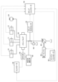
図1は、実施形態に基づく作業機械100の外観図である。
<Overall configuration of working machine>
FIG. 1 is an external view of a
図1に示されるように、本開示の思想を適用可能な作業機械として油圧により作動する作業機2を備える油圧ショベルを例に挙げて説明する。 As shown in FIG. 1, a hydraulic excavator including a hydraulically operated working machine 2 will be described as an example of a working machine to which the idea of the present disclosure can be applied.
油圧ショベルは、車両本体1と、作業機2とを備える。
車両本体1は、旋回体3と、運転室4と、走行装置5とを有する。
The hydraulic excavator includes a
The
旋回体3は、走行装置5の上に配置される。走行装置5は、旋回体3を支持する。旋回体3は、旋回軸AXを中心に旋回可能である。運転室4には、オペレータが着座する運転席4Sが設けられる。オペレータは、運転室4において油圧ショベルを操作する。走行装置5は、一対の履帯5Crを有する。履帯5Crの回転により、油圧ショベルが走行する。走行装置5は、車輪(タイヤ)で構成されていてもよい。
The revolving body 3 is arranged on the
実施形態では、運転席4Sに着座したオペレータを基準として各部の位置関係について説明する。前後方向とは、運転席4Sに着座したオペレータの前後方向をいう。左右方向とは、運転席4Sに着座したオペレータを基準とした左右方向をいう。左右方向は、車両の幅方向(車幅方向)に一致する。運転席4Sに着座したオペレータに正面に正対する方向を前方向とし、前方向とは反対の方向を後方向とする。運転席4Sに着座したオペレータが正面に正対したとき右側、左側をそれぞれ右方向、左方向とする。
In the embodiment, the positional relationship of each part will be described with reference to the operator seated in the driver's
旋回体3は、エンジンが収容されるエンジンルーム9と、旋回体3の後部に設けられるカウンタウェイトとを有する。旋回体3において、エンジンルーム9の前方に手すり19が設けられる。エンジンルーム9には、エンジン及び油圧ポンプなどが配置されている。
The revolving structure 3 has an
作業機2は、旋回体3に支持される。作業機2は、ブーム6と、アーム7と、バケット8と、ブームシリンダ10と、アームシリンダ11と、バケットシリンダ12とを有する。
The work machine 2 is supported by a revolving body 3. The work machine 2 includes a
ブーム6は、ブームピン13を介して旋回体3に接続される。アーム7は、アームピン14を介してブーム6に接続される。バケット8は、バケットピン15を介してアーム7に接続される。ブームシリンダ10は、ブーム6を駆動する。アームシリンダ11は、アーム7を駆動する。バケットシリンダ12は、バケット8を駆動する。ブーム6の基端部(ブームフート)と旋回体3とが接続される。ブーム6の先端部(ブームトップ)とアーム7の基端部(アームフート)とが接続される。アーム7の先端部(アームトップ)とバケット8の基端部とが接続される。ブームシリンダ10、アームシリンダ11およびバケットシリンダ12はいずれも、作動油によって駆動される油圧シリンダである。
The
ブーム6は、中心軸であるブームピン13を中心に旋回体3に対して回転可能である。アーム7は、ブームピン13と平行な中心軸であるアームピン14を中心にブーム6に対して回転可能である。バケット8は、ブームピン13およびアームピン14と平行な中心軸であるバケットピン15を中心にアーム7に対して回転可能である。
The
なお、バケット8、作業機2は、本開示の「バケット」、「作業機」の一例である。
〔制御系の構成〕
図2は、実施形態に基づく作業機械100の制御系の構成を説明する図である。
Note that the
[Control system configuration]
FIG. 2 is a diagram illustrating the configuration of the control system of the
図2を参照して、作業機械100は、ブームシリンダ10と、アームシリンダ11と、バケットシリンダ12と、旋回モータ24と、コントローラ26と、エンジンコントローラ30と、エンジン38と、油圧ポンプ40と、メインバルブ25と、リリーフ弁44と、ポンプ圧力センサ32と、ポンプコントローラ34と、自己圧減圧弁46と、EPC弁50とを備えている。
Referring to FIG. 2,
エンジン38は、例えば、ディーゼル式のエンジンであり、エンジンコントローラ30の制御に従って制御される。具体的には、エンジンコントローラ30は、図示しない燃料噴射装置からの燃料の噴射量を制御することにより、エンジン38の出力トルクと回転数とを制御する。
The
油圧ポンプ40は、エンジン38によって駆動され、作動油を吐出する。油圧ポンプ40は、エンジン38の回転数に応じて作動油の吐出量を変化させる固定容量型の油圧ポンプである。なお、本例においては、1つの油圧ポンプ40を用いた構成について説明するが、特にこれに限られず複数の油圧ポンプを用いた構成とすることも可能である。
メインバルブ25は、油圧ポンプ40から供給される作動油を受けて、ブームシリンダ10,アームシリンダ11,バケットシリンダ12および旋回モータ24にそれぞれ作動油を分配して供給する。
The
コントローラ26は、EPC弁50に指令電流を出力する。EPC弁50は、コントローラ26からの指令電流に従って、メインバルブ25を制御する。
The
実施形態に従うコントローラ26は、CPU(Central Processing Unit)およびメモリ等で構成され、メモリに格納されている制御プログラムを実行することにより、作業機2を制御する。一例として、メモリには、作業機2を自動制御して複数の作業工程を実行する制御プログラムが格納されている。具体的には、複数の作業工程として、作業地形に対して作業機2を用いて掘削動作を実行する掘削工程、旋回体3により旋回動作する旋回工程、掘削動作によりバケット8に抱え込まれた掘削対象物に対して作業機2を用いて排土動作する排土工程を含む。
The
コントローラ26は、自動制御の複数の作業工程の各作業工程を示す状態データをメモリに保持するとともに、当該状態データをポンプコントローラ34に出力する。一例として、コントローラ26は、自動掘削状態データ、自動旋回状態データ、自動排土状態データの少なくともいずれかの状態データを保持するとともに、当該状態データをポンプコントローラ34に出力する。ポンプコントローラ34は、コントローラ26から出力された状態データに基づいて、例えば自動掘削状態であることを判断することが可能である。
The
なお、本例においては、コントローラ26が状態データを出力する場合について説明するが特にこれに限られず、ポンプコントローラ34がコントローラ26にアクセスしてメモリに格納された状態データを取得するようにしても良い。
In this example, a case will be described in which the
油圧ポンプ40から出力された作動油は、自己圧減圧弁46によって一定の圧力に減らされてパイロット用に供給される。
The hydraulic oil output from the
ポンプ圧力センサ32は、油圧ポンプ40とメインバルブ25との間の油圧回路内の作動油の圧力を検出する。
リリーフ弁44は、油圧ポンプ40と、メインバルブ25との間の流路を有する油圧回路に接続されている。また、リリーフ弁44は、油圧回路が所定のリリーフ圧よりも高い場合には開いて作動油をタンクへ流す。リリーフ弁44により油圧回路を流れる作動油の圧力を所定の圧力以下に補償することが可能となる。リリーフ弁44は、所定のリリーフ圧を第1の設定圧あるいは第1の設定圧よりも高い第2の設定圧に変更可能に設けられている。
The
ポンプコントローラ34は、ポンプ圧力センサ32で検出された油圧回路の作動油の圧力のデータの入力を受ける。ポンプコントローラ34は、ブームシリンダ10、アームシリンダ11、バケットシリンダ12からのシリンダ長のデータの入力を受ける。ポンプコントローラ34は、コントローラ26から自動制御の状態に関するデータの入力を受ける。ポンプコントローラ34は、ポンプ圧力センサ32で検出された油圧回路の作動油の圧力のデータ、ブームシリンダ10、アームシリンダ11、バケットシリンダ12からのシリンダ長のデータ、自動制御の状態に関するデータとに基づいてリリーフ弁44のリリーフ圧を調整する。
The
なお、油圧ポンプ40、リリーフ弁44およびブームシリンダ10、アームシリンダ11、バケットシリンダ12は、本開示の「油圧ポンプ」、「リリーフ弁」および「油圧シリンダ」の一例である。
Note that the
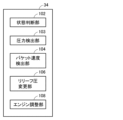
図3は、実施形態に基づく作業機械100のポンプコントローラ34の機能ブロックを説明する図である。
FIG. 3 is a diagram illustrating functional blocks of the
図3に示されるように、ポンプコントローラ34は、状態判断部102と、圧力検出部103と、バケット速度検出部104と、リリーフ圧変更部106と、エンジン調整部108とを含む。
As shown in FIG. 3, the
状態判断部102は、コントローラ26から自動制御の状態に関するデータの入力を受けて、作業機の制御状態が自動掘削状態か否かを判断する。
The
圧力検出部103は、ポンプ圧力センサ32で検出された油圧回路の作動油の圧力のデータの入力を受ける。
The
バケット速度検出部104は、ブームシリンダ10、アームシリンダ11およびバケットシリンダ12のそれぞれに設けられたセンサからのシリンダ長データの入力を受け付ける、当該シリンダ長データに基づいてバケット速度を検出する。
The bucket
リリーフ圧変更部106は、圧力検出部103で入力を受け付けた油圧回路のポンプ圧と、バケット速度検出部104で検出されたバケット速度と、状態判断部102で判断された作業機の制御状態とに基づいてリリーフ弁44のリリーフ圧を変更する。
The relief
リリーフ弁44は、第1の設定圧に予め設定されている。リリーフ圧変更部106は、所定条件が成立した場合に、リリーフ弁44のリリーフ圧を第1の設定圧よりも高い第2の設定圧に変更する。
The
エンジン調整部108は、エンジン38の回転数を調整するようにエンジンコントローラ30に指示する。
なお、状態判断部102、圧力検出部103、バケット速度検出部104、リリーフ圧変更部106、エンジン調整部108は、本開示の「状態判断部」、「圧力検出部」、「速度検出部」、「リリーフ圧変更部」、「エンジン調整部」の一例である。
Note that the
<ポンプコントローラの制御>
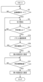
図4は、実施形態に従うポンプコントローラ34の制御フローを説明する図である。
<Pump controller control>
FIG. 4 is a diagram illustrating a control flow of the
図4を参照して、ポンプコントローラ34は、自動掘削モードであるか否かを判断する(ステップS2)。具体的には、状態判断部102は、コントローラ26からの状態データの入力を受けて自動掘削モードであるか否かを判断する。
Referring to FIG. 4, pump
ステップS2において、ポンプコントローラ34は、自動掘削モードであると判断しない場合(ステップS2においてNO)には、ステップS2の判断を繰り返す。
In step S2, if the
一方、ステップS2において、ポンプコントローラ34は、自動掘削モードであると判断した場合(ステップS2においてYES)には、作動油の圧力を検出する(ステップS4)。具体的には、圧力検出部103は、ポンプ圧力センサ32で検出された作動油の圧力を取得する。なお、圧力検出部103は、ブームシリンダ10、アームシリンダ11、バケットシリンダ12のヘッド側とボトム側に取り付けた圧力センサで検出された作動油の圧力を取得しても良い。
On the other hand, in step S2, if the
次に、ポンプコントローラ34は、取得した圧力が所定値以上であるか否かを判断する(ステップS6)。具体的には、リリーフ圧変更部106は、圧力検出部103で取得した作動油の圧力が所定値以上の圧力であるか否かを判断する。ポンプ圧力センサ32で検出された作動油の圧力が所定値以上の圧力であると判断される場合には、掘削負荷の高い作業工程と判断することが可能である。
Next, the
ステップS6において、ポンプコントローラ34は、作動油の圧力が所定値以上であると判断した場合(ステップS6においてYES)には、バケット速度を取得する(ステップS7A)。リリーフ圧変更部106は、バケット速度検出部104に対してバケット速度を算出するように指示する。バケット速度検出部104は、ブームシリンダ10、アームシリンダ11、バケットシリンダ12からのシリンダ長のデータに基づいて作業機2のバケット8の速度を算出する。バケット速度検出部104は、算出したバケット8の速度をリリーフ圧変更部106に出力する。
In step S6, if the
次に、ポンプコントローラ34は、バケット速度が所定速度以下であるか否かを判断する(ステップS7B)。具体的には、リリーフ圧変更部106は、バケット速度検出部104から出力されたバケット速度が所定速度以下(例えば速度が0)であるか否かを判断する。バケット速度検出部104から出力されたバケット速度が所定速度以下であると判断される場合には、掘削負荷の高い作業工程と判断することが可能である。
Next, the
ステップS7Bにおいて、ポンプコントローラ34は、所定速度以下であると判断した場合(ステップS7BにおいてYES)には、リリーフ圧を第2の設定圧に設定する(ステップS8)。具体的には、リリーフ圧変更部106は、バケット速度検出部104から出力されたバケット速度が所定速度以下であると判断した場合にはリリーフ弁44のリリーフ圧を第2の設定圧に変更する。
In step S7B, if the
次に、ポンプコントローラ34は、リリーフ圧を第2の設定圧に設定してから所定期間経過したか否かを判断する(ステップS10)。リリーフ圧変更部106は、リリーフ圧を第2の設定圧に設定してから所定期間経過したか否かを判断する。
Next, the
一方、ステップS10において、ポンプコントローラ34は、リリーフ圧を第2の設定圧に設定してから所定期間経過していないと判断した場合(ステップS10においてNO)には、ステップS10の判断を繰り返す。
On the other hand, in step S10, if the
次に、ポンプコントローラ34は、ステップS10において、リリーフ圧を第2の設定圧に設定してから所定期間経過したと判断した場合(ステップS10においてYES)には、リリーフ圧を第1の設定圧に設定する(ステップS12)。そして、処理を終了する(エンド)。具体的には、リリーフ圧変更部106は、リリーフ圧を第2の設定圧に設定してから所定期間経過したと判断した場合にはリリーフ弁44のリリーフ圧を第1の設定圧に変更する。これにより、長期間の間、リリーフ圧を高い状態に維持することによる油圧回路の負荷を軽減することが可能である。
Next, in step S10, if the
一方、ステップS6において、ポンプコントローラ34は、作動油の圧力が所定値以上でないと判断した場合(ステップS6においてNO)には、ステップS4に戻り、上記処理を繰り返す。
On the other hand, if the
一方、ステップS7Bにおいて、ポンプコントローラ34は、バケット速度が所定速度以下でないと判断した場合(ステップS7BにおいてNO)には、ステップS4に戻り、上記処理を繰り返す。
On the other hand, if the
実施形態においては、リリーフ圧変更部106は、コントローラ26から出力される制御の状態が自動掘削モードであり、油圧回路の作動油の圧力が所定圧以上、かつ、バケット8の速度が所定速度以下(例えば停止状態)である場合に、リリーフ弁44のリリーフ圧を第1の設定圧よりも高い第2の設定圧に変更する。
In the embodiment, the relief
リリーフ弁44のリリーフ圧を第1の設定圧から第2の設定圧に変更することにより油圧回路内の作動油の圧力を高めることが可能である。したがって、掘削負荷の高い自動掘削の制御を実行する場合に、メインバルブ25と接続される作業機2の出力を上昇(パワーアップ)させて動作させることが可能となる。
By changing the relief pressure of the
なお、上記の実施形態のリリーフ圧変更部106は、所定条件として、自動掘削モードが実行されており、油圧回路の作動油の圧力が所定圧以上、かつ、バケット8の速度が所定速度以下である場合に、リリーフ弁44のリリーフ圧を第1の設定圧よりも高い第2の設定圧に変更する場合について説明した。これに限られず、リリーフ圧変更部106は、自動掘削モードであり、油圧回路の作動油の圧力およびバケット8の速度の少なくとも一方に基づいてリリーフ弁44のリリーフ圧を変更しても良い。具体的には、リリーフ圧変更部106は、自動掘削モード、かつ、油圧回路の作動油の圧力が所定圧以上およびバケット8の速度が所定速度以下の少なくとも一方である場合に、リリーフ弁44のリリーフ圧を第1の設定圧よりも高い第2の設定圧に変更してもよい。
Note that the relief
なお、上記の例においては、リリーフ圧変更部106は、所定期間の間、リリーフ圧が第2の設定圧として設定されていると判断した場合にはリリーフ弁44のリリーフ圧を第1の設定圧に変更する場合について説明した。
In the above example, if the relief
一方で、掘削負荷が低くなった場合には、リリーフ弁44のリリーフ圧を第1の設定圧に変更するようにしてもよい。
On the other hand, when the excavation load becomes low, the relief pressure of the
例えば、作業機の速度が回復した場合にはリリーフ弁44のリリーフ圧を第1の設定圧に変更するようにしてもよい。具体的には、リリーフ圧変更部106は、バケット8の速度が所定速度を超えた場合にはリリーフ弁44のリリーフ圧を第1の設定圧に変更するようにしてもよい。あるいは、リリーフ圧変更部106は、油圧回路の作動油の圧力が所定圧未満となった場合にはリリーフ弁44のリリーフ圧を第1の設定圧に変更するようにしてもよい。
For example, when the speed of the work machine is restored, the relief pressure of the
また、リリーフ圧変更部106は、掘削状態が終了したと判断した場合には、リリーフ弁44のリリーフ圧を第1の設定圧に変更するようにしてもよい。例えば、リリーフ圧変更部106は、コントローラ26からの自動制御の状態に関するデータの入力に基づいて掘削状態が終了して旋回状態に動作が移行したと判断した場合には、リリーフ弁44のリリーフ圧を第1の設定圧に変更するようにしてもよい。あるいは、視覚センサを用いてバケット8の刃先が地面から出たと判断した場合には、掘削状態が終了したと判断してリリーフ弁44のリリーフ圧を第1の設定圧に変更するようにしてもよい。具体的には、リリーフ圧変更部106は、視覚センサを用いてバケット8の刃先が現況地形高さを超えたと判断した場合にはリリーフ弁44のリリーフ圧を第1の設定圧に変更するようにしてもよい。あるいは、作業機の姿勢に基づいて掘削状態が終了したと判断した場合には、リリーフ弁44のリリーフ圧を第1の設定圧に変更するようにしてもよい。具体的には、リリーフ圧変更部106は、ブームシリンダ10、アームシリンダ11、バケットシリンダ12からのシリンダ長のデータに基づいてバケット8の姿勢がバケット8の内部の土を抱え込んだ姿勢であると判断した場合にはリリーフ弁44のリリーフ圧を第1の設定圧に変更するようにしてもよい。
Further, the relief
<変形例1>
自動掘削モード中に障害物(例えば岩など)に衝突して瞬間的にバケット8の速度が0になったり、作動油の圧力が所定値以上になる可能性がある。その場合に、リリーフ圧変更部106は、リリーフ弁44のリリーフ圧を第1の設定圧よりも高い第2の設定圧に変更する可能性がある。
<
During the automatic excavation mode, the
本変形例1においては、当該誤動作を防止する方式について説明する。
具体的には、リリーフ圧変更部106は、誤動作を防止するために掘削負荷の高い状態が所定期間継続するか否かを条件に加える。
In
Specifically, the relief
例えば、リリーフ圧変更部106は、所定条件として、自動掘削モードが実行されており、油圧回路の作動油の圧力が所定期間、所定値以上を継続し、かつ、バケット8の速度が所定期間、所定速度以下を継続している場合にリリーフ弁44のリリーフ圧を第1の設定圧よりも高い第2の設定圧に変更してもよい。
For example, the relief
別の方式として、フィルタ回路を用いて移動平均処理した後の計測値を用いて判定してもよい。 As another method, the determination may be made using a measured value that has been subjected to moving average processing using a filter circuit.
具体的には、圧力検出部103に移動平均処理するフィルタ回路を設けて、当該フィルタ回路を通過した後の計測値をリリーフ圧変更部106に出力するようにしても良い。あるいは、バケット速度検出部104に、移動平均処理するフィルタ回路を設けて、当該フィルタ回路を通過した後の算出値をリリーフ圧変更部106に出力するようにしても良い。
Specifically, the
実施形態の変形例1に基づく処理により突発的に生じた外乱を除去することが可能となり、誤動作を防止することが可能である。 The processing based on the first modification of the embodiment makes it possible to remove sudden disturbances and prevent malfunctions.
なお、本例においては、リリーフ弁44のリリーフ圧を第1の設定圧から第2の設定圧に変更する場合の条件について説明したが、リリーフ弁44のリリーフ圧を第2の設定圧から第1の設定圧に変更する場合についても同様に適用可能である。
In this example, the conditions for changing the relief pressure of the
<変形例2>
上記の実施形態においては、掘削負荷の高い自動掘削の制御を実行する場合に、リリーフ弁44のリリーフ圧を第1の設定圧から第2の設定圧に変更することにより油圧回路内の作動油の圧力を高めて作業機2の出力を上昇(パワーアップ)させる場合について説明した。この点で、リリーフ圧変更部106は、リリーフ弁44のリリーフ圧を第1の設定圧よりも高い第2の設定圧に変更するとともに、エンジン調整部108にエンジンの回転数を調整するように指示する。
<Modification 2>
In the above embodiment, when controlling automatic excavation with a high excavation load, the relief pressure of the
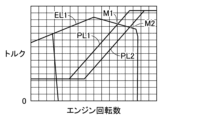
図5は、実施形態に従うポンプ吸収トルクとエンジン回転数との関係を説明する図である。 FIG. 5 is a diagram illustrating the relationship between pump absorption torque and engine speed according to the embodiment.
図5に示されるように、エンジン38のエンジン出力特性線EL1が示されている。そして、エンジン出力特性線EL1と、ポンプ吸収トルク特性線PLとに基づいてポンプ吸収トルクがエンジン出力トルクとマッチング点でマッチングするようにEPC弁50で制御される。本例においては、ポンプ吸収トルク特性線PL1と、ポンプ吸収トルク特性線PL2とが設けられており、通常時には、ポンプ吸収トルク特性線PL1とエンジン出力特性線EL1とのマッチング点M1でマッチングするように制御される。そして、掘削負荷の高い自動掘削の制御を実行する場合には、ポンプ吸収トルク特性線PL1をポンプ吸収トルク特性線PL2に変更する。これにより、ポンプ吸収トルク特性線PL1とエンジン出力特性線EL2とのマッチング点M2でマッチングするように制御される。具体的には、エンジン調整部108は、エンジンコントローラ30に指示してエンジン回転数を上昇させる。
As shown in FIG. 5, an engine output characteristic line EL1 of the
実施形態の変形例2においては、掘削負荷の高い自動掘削の制御を実行する場合に、リリーフ弁44のリリーフ圧を第1の設定圧から第2の設定圧に変更することにより油圧回路内の作動油の圧力を高めるとともに、エンジン回転数を上昇させることにより作業機2の出力をさらに上昇(パワーアップ)させることが可能である。
In the second modification of the embodiment, when controlling automatic excavation with a high excavation load, the relief pressure in the
上記の実施形態では、主に自動掘削の制御を実行する場合に作業機2の出力を上昇させる方式について説明したが特に自動掘削の制御の際に限られず、通常の掘削制御を実行する場合にも同様に適用可能である。具体的には、コントローラ26からの制御の状態に関するデータの入力に基づいて掘削状態と判断した場合には、図4で説明したフローを実行するようにしてもよい。例えば、ステップS2における自動掘削モードであるか否かの判断処理の代わりに、掘削状態であるか否かを判断する処理を実行して、掘削状態であれば図4で説明したステップS2以降のフローを実行するようにしてもよい。あるいは、視覚センサを用いてバケット8の刃先が地面に入ったと判断した場合には、掘削状態であると判断して図4で説明したステップS2以降のフローを実行するようにしてもよい。あるいは、作業機の姿勢に基づいて掘削状態であると判断した場合には、図4で説明したステップS2以降のフローを実行するようにしてもよい。
In the above embodiment, the method of increasing the output of the working machine 2 mainly when executing automatic excavation control was described, but it is not limited to the case of automatic excavation control in particular, but can be applied when executing normal excavation control. is similarly applicable. Specifically, when it is determined that the excavation state is based on the input of data regarding the control state from the
上記の実施形態では、バケット速度検出部104は、ブームシリンダ10、アームシリンダ11、バケットシリンダ12からのシリンダ長のデータに基づいて作業機2のバケット8の速度を算出する方式について説明したが、これに限られず、IMU(inertial measurement unit)を用いてバケット8の速度を検出しても良い。
In the embodiment described above, the bucket
運転室4の前面に取り付けた視覚センサ(Lidar、ステレオカメラ等)を用いて、バケット8の特徴量を取得し、当該特徴量の動きに基づいてバケット8の速度を検出してもよい。あるいは、バケット8にマーカを取り付けて当該マーカの動きに基づいてバケット8の速度を検出しても良い。
The feature amount of the
上記の実施形態では、作業機械の一例として油圧ショベルを挙げているが油圧ショベルに限らず、ブルドーザ、ホイールローダ等の他の種類の作業機械にも適用可能である。 In the above embodiment, a hydraulic excavator is cited as an example of a working machine, but the present invention is not limited to a hydraulic excavator, but can be applied to other types of working machines such as a bulldozer and a wheel loader.
以上、本開示の実施形態について説明したが、今回開示された実施形態は全ての点で例示であって制限的なものではないと考えられるべきである。本開示の範囲は請求の範囲によって示され、請求の範囲と均等の意味および範囲内での全ての変更が含まれることが意図される。 Although the embodiments of the present disclosure have been described above, the embodiments disclosed this time should be considered to be illustrative in all respects and not restrictive. The scope of the present disclosure is indicated by the claims, and it is intended that all changes within the meaning and range equivalent to the claims are included.
1 車両本体、2 作業機、3 旋回体、4 運転室、4S 運転席、5 走行装置、5Cr 履帯、6 ブーム、7 アーム、8 バケット、8A 刃先、9 エンジンルーム、10 ブームシリンダ、11 アームシリンダ、12 バケットシリンダ、13 ブームピン、14 アームピン、15 バケットピン、19 手すり、21 アンテナ、21A 第1アンテナ、21B 第2アンテナ、26 コントローラ、30 エンジンコントローラ、32 ポンプ圧力センサ、38 エンジン、40 油圧ポンプ、44 リリーフ弁、46 自己圧減圧弁、50 EPC弁。 1 Vehicle body, 2 Work equipment, 3 Swinging structure, 4 Driver's cab, 4S Driver's seat, 5 Traveling device, 5Cr Track, 6 Boom, 7 Arm, 8 Bucket, 8A Cutting edge, 9 Engine room, 10 Boom cylinder, 11 Arm cylinder , 12 bucket cylinder, 13 boom pin, 14 arm pin, 15 bucket pin, 19 handrail, 21 antenna, 21A first antenna, 21B second antenna, 26 controller, 30 engine controller, 32 pump pressure sensor, 38 engine, 40 hydraulic pump, 44 relief valve, 46 self-pressure reducing valve, 50 EPC valve.
Claims (13)
作動油によって前記作業機を動作させる油圧シリンダと、
油圧回路を介して前記油圧シリンダに前記作動油を供給する油圧ポンプと、
前記油圧回路のリリーフ圧を、第1の設定圧および前記第1の設定圧よりも高い第2の設定圧のいずれかに設定可能なリリーフ弁と、
前記作業機の制御状態が掘削状態か否かを判断する状態判断部と、
前記油圧回路の前記作動油の圧力および前記作業機の速度を検出する検出部と、
前記作業機の制御状態が掘削状態である場合に、前記油圧回路の前記作動油の圧力および前記作業機の速度の検出値に基づいて前記リリーフ弁のリリーフ圧を前記第1の設定圧から前記第2の設定圧に変更するリリーフ圧変更部とを備える、作業機械。 work equipment and
a hydraulic cylinder that operates the work machine using hydraulic oil;
a hydraulic pump that supplies the hydraulic oil to the hydraulic cylinder via a hydraulic circuit;
a relief valve that can set the relief pressure of the hydraulic circuit to either a first set pressure or a second set pressure higher than the first set pressure;
a state determination unit that determines whether the control state of the work machine is an excavation state;
a detection unit that detects the pressure of the hydraulic oil in the hydraulic circuit and the speed of the work machine;
When the control state of the work machine is an excavation state, the relief pressure of the relief valve is changed from the first set pressure based on the pressure of the hydraulic oil in the hydraulic circuit and the detected value of the speed of the work machine. A working machine, comprising: a relief pressure changing section that changes the pressure to the second set pressure.
前記圧力検出部によって検出された前記作動油の圧力が所定値よりも大きい場合には、前記エンジンの回転数を増大させるエンジン調整部をさらに備える、請求項1記載の作業機械。 The hydraulic pump is driven by an engine,
The working machine according to claim 1, further comprising an engine adjustment section that increases the rotation speed of the engine when the pressure of the hydraulic oil detected by the pressure detection section is higher than a predetermined value.
前記リリーフ圧変更部は、前記作業機の制御状態が掘削状態であり、前記油圧回路の前記作動油の圧力が所定期間の間、所定値以上および前記バケットの速度が所定期間の間、所定速度以下である場合に前記リリーフ弁のリリーフ圧を前記第1の設定圧から前記第2の設定圧に変更する、請求項1記載の作業機械。 The work machine has a bucket,
The relief pressure changing unit is configured such that when the control state of the work machine is an excavation state, the pressure of the hydraulic fluid in the hydraulic circuit is equal to or higher than a predetermined value for a predetermined period, and the speed of the bucket is set to a predetermined speed for a predetermined period. The working machine according to claim 1, wherein the relief pressure of the relief valve is changed from the first set pressure to the second set pressure when the pressure is below.
作動油によって前記作業機を動作させる油圧シリンダと、
油圧回路を介して前記油圧シリンダに前記作動油を供給する油圧ポンプと、
前記油圧回路のリリーフ圧を、第1の設定圧および前記第1の設定圧よりも高い第2の設定圧のいずれかに設定可能なリリーフ弁と、
前記作業機の制御状態が掘削状態か否かを判断する状態判断部と、
前記油圧回路の前記作動油の圧力および前記作業機の速度を検出する検出部と、
前記作業機の制御状態が掘削状態である場合に、前記油圧回路の前記作動油の圧力および前記作業機の速度の検出値に基づいて前記リリーフ弁のリリーフ圧を前記第1の設定圧から前記第2の設定圧に変更するリリーフ圧変更部とを備え、
前記作業機は、バケットを有し、
前記リリーフ圧変更部は、前記リリーフ弁のリリーフ圧を前記第2の設定圧に変更後、前記油圧回路の前記作動油の圧力が所定値未満および前記バケットの速度が所定速度より大きい速度の少なくとも一方である場合に前記第1の設定圧に変更する、作業機械。 work equipment and
a hydraulic cylinder that operates the work machine using hydraulic oil;
a hydraulic pump that supplies the hydraulic oil to the hydraulic cylinder via a hydraulic circuit;
a relief valve that can set the relief pressure of the hydraulic circuit to either a first set pressure or a second set pressure higher than the first set pressure;
a state determination unit that determines whether the control state of the work machine is an excavation state;
a detection unit that detects the pressure of the hydraulic oil in the hydraulic circuit and the speed of the work machine;
When the control state of the work equipment is an excavation state, the relief pressure of the relief valve is changed from the first set pressure to the and a relief pressure changing section for changing to a second set pressure,
The work machine has a bucket,
After changing the relief pressure of the relief valve to the second set pressure, the relief pressure changing section changes the pressure of the hydraulic fluid in the hydraulic circuit to at least a predetermined value and the speed of the bucket to be higher than a predetermined speed. A work machine that changes to the first set pressure in one case .
作動油によって前記作業機を動作させる油圧シリンダと、
油圧回路を介して前記油圧シリンダに前記作動油を供給する油圧ポンプと、
前記油圧回路のリリーフ圧を、第1の設定圧および前記第1の設定圧よりも高い第2の設定圧のいずれかに設定可能なリリーフ弁と、
前記作業機の制御状態が掘削状態か否かを判断する状態判断部と、
前記油圧回路の前記作動油の圧力および前記作業機の速度を検出する検出部と、
前記作業機の制御状態が掘削状態である場合に、前記油圧回路の前記作動油の圧力および前記作業機の速度の検出値に基づいて前記リリーフ弁のリリーフ圧を前記第1の設定圧から前記第2の設定圧に変更するリリーフ圧変更部とを備え、
前記作業機は、バケットを有し、
リリーフ圧変更部は、前記作業機の制御状態が掘削状態であり、前記油圧回路の前記作
動油の圧力が所定値以上および前記バケットの速度が所定速度以下である場合に前記リリーフ弁のリリーフ圧を前記第1の設定圧から前記第2の設定圧に変更する、作業機械。 work equipment and
a hydraulic cylinder that operates the work machine using hydraulic oil;
a hydraulic pump that supplies the hydraulic oil to the hydraulic cylinder via a hydraulic circuit;
a relief valve that can set the relief pressure of the hydraulic circuit to either a first set pressure or a second set pressure higher than the first set pressure;
a state determination unit that determines whether the control state of the work machine is an excavation state;
a detection unit that detects the pressure of the hydraulic oil in the hydraulic circuit and the speed of the work machine;
When the control state of the work machine is an excavation state, the relief pressure of the relief valve is changed from the first set pressure based on the pressure of the hydraulic oil in the hydraulic circuit and the detected value of the speed of the work machine. and a relief pressure changing section that changes the pressure to the second set pressure,
The work machine has a bucket,
The relief pressure changing unit is configured to control the operation of the hydraulic circuit when the control state of the work machine is an excavation state.
A work machine that changes the relief pressure of the relief valve from the first set pressure to the second set pressure when the pressure of hydraulic oil is above a predetermined value and the speed of the bucket is below a predetermined speed.
前記作業機の制御状態が掘削状態である場合に前記作業機を動作させる油圧シリンダに油圧回路を介して供給される作動油の圧力および前記作業機の速度を検出するステップと、
前記油圧回路の前記作動油の圧力および前記作業機の速度の検出値に基づいて前記油圧回路のリリーフ弁のリリーフ圧を第1の設定圧から前記第1の設定圧よりも高い第2の設定圧に変更するステップとを備える、作業機械の制御方法。 a step of determining whether the control state of the work machine is in the digging state;
detecting the pressure of hydraulic oil supplied via a hydraulic circuit to a hydraulic cylinder that operates the work machine when the control state of the work machine is an excavation state, and the speed of the work machine;
Setting the relief pressure of the relief valve of the hydraulic circuit from a first setting pressure to a second setting higher than the first setting pressure based on the detected values of the pressure of the hydraulic oil in the hydraulic circuit and the speed of the work machine. A method for controlling a working machine, comprising the step of changing the pressure to the pressure.
前記作業機の制御状態が掘削状態である場合に前記作業機を動作させる油圧シリンダに油圧回路を介して供給される作動油の圧力および前記作業機の速度を検出するステップと、detecting the pressure of hydraulic oil supplied via a hydraulic circuit to a hydraulic cylinder that operates the work machine when the control state of the work machine is an excavation state, and the speed of the work machine;
前記油圧回路の前記作動油の圧力および前記作業機の速度の検出値に基づいて前記油圧回路のリリーフ弁のリリーフ圧を第1の設定圧から前記第1の設定圧よりも高い第2の設定圧に変更するステップと、Setting the relief pressure of the relief valve of the hydraulic circuit from a first setting pressure to a second setting higher than the first setting pressure based on the detected values of the pressure of the hydraulic oil in the hydraulic circuit and the speed of the work machine. a step of changing the pressure to
前記リリーフ弁のリリーフ圧を前記第2の設定圧に変更後、前記油圧回路の前記作動油の圧力が所定値未満および前記バケットの速度が所定速度より大きい速度の少なくとも一方である場合に前記第1の設定圧に変更するステップとを備える、作業機械の制御方法。After changing the relief pressure of the relief valve to the second set pressure, if the pressure of the hydraulic oil in the hydraulic circuit is less than a predetermined value and the speed of the bucket is at least one of a speed greater than the predetermined speed, A method for controlling a working machine, comprising the step of changing the pressure to a set pressure of 1.
前記作業機の制御状態が掘削状態である場合に前記作業機を動作させる油圧シリンダに油圧回路を介して供給される作動油の圧力および前記作業機の速度を検出するステップと、
前記作業機の制御状態が掘削状態であり、前記油圧回路の前記作動油の圧力が所定値以上および前記バケットの速度が所定速度以下である場合に前記油圧回路のリリーフ弁のリリーフ圧を第1の設定圧から前記第1の設定圧よりも高い第2の設定圧に変更するステップとを備える、作業機械の制御方法。 determining whether the control state of the work machine having the bucket is in the digging state;
detecting the pressure of hydraulic oil supplied via a hydraulic circuit to a hydraulic cylinder that operates the work machine when the control state of the work machine is an excavation state, and the speed of the work machine;
When the control state of the work machine is an excavation state, the pressure of the hydraulic oil in the hydraulic circuit is a predetermined value or more, and the speed of the bucket is below a predetermined speed, the relief pressure of the relief valve of the hydraulic circuit is set to the first level. A method for controlling a working machine, the method comprising: changing the set pressure from the set pressure to a second set pressure higher than the first set pressure.
Priority Applications (6)
| Application Number | Priority Date | Filing Date | Title |
|---|---|---|---|
| JP2019134035A JP7368130B2 (en) | 2019-07-19 | 2019-07-19 | Work machines and work machine control methods |
| DE112020002415.6T DE112020002415T5 (en) | 2019-07-19 | 2020-06-30 | Work machine and method for controlling the same |
| PCT/JP2020/025654 WO2021014900A1 (en) | 2019-07-19 | 2020-06-30 | Work machine and method for controlling work machine |
| CN202080045084.4A CN114008275B (en) | 2019-07-19 | 2020-06-30 | Work machine and control method for work machine |
| US17/618,954 US12098515B2 (en) | 2019-07-19 | 2020-06-30 | Work machine and method for controlling the same |
| KR1020217040452A KR102641393B1 (en) | 2019-07-19 | 2020-06-30 | Working machines and control methods of working machines |
Applications Claiming Priority (1)
| Application Number | Priority Date | Filing Date | Title |
|---|---|---|---|
| JP2019134035A JP7368130B2 (en) | 2019-07-19 | 2019-07-19 | Work machines and work machine control methods |
Publications (2)
| Publication Number | Publication Date |
|---|---|
| JP2021017737A JP2021017737A (en) | 2021-02-15 |
| JP7368130B2 true JP7368130B2 (en) | 2023-10-24 |
Family
ID=74193774
Family Applications (1)
| Application Number | Title | Priority Date | Filing Date |
|---|---|---|---|
| JP2019134035A Active JP7368130B2 (en) | 2019-07-19 | 2019-07-19 | Work machines and work machine control methods |
Country Status (6)
| Country | Link |
|---|---|
| US (1) | US12098515B2 (en) |
| JP (1) | JP7368130B2 (en) |
| KR (1) | KR102641393B1 (en) |
| CN (1) | CN114008275B (en) |
| DE (1) | DE112020002415T5 (en) |
| WO (1) | WO2021014900A1 (en) |
Families Citing this family (3)
| Publication number | Priority date | Publication date | Assignee | Title |
|---|---|---|---|---|
| US20230097563A1 (en) * | 2021-09-28 | 2023-03-30 | Deere & Company | System and method for blade control on a utility vehicle |
| US20230272599A1 (en) * | 2022-02-28 | 2023-08-31 | Caterpillar Inc. | Work machine safety zone control |
| CN119487265A (en) * | 2022-09-30 | 2025-02-18 | 日立建机株式会社 | Wheel Loader |
Citations (3)
| Publication number | Priority date | Publication date | Assignee | Title |
|---|---|---|---|---|
| JP2004190749A (en) | 2002-12-10 | 2004-07-08 | Shin Caterpillar Mitsubishi Ltd | Automatic booster of working machine |
| JP2010156134A (en) | 2008-12-26 | 2010-07-15 | Komatsu Ltd | Working vehicle and control method for working vehicle |
| JP2011157789A (en) | 2010-02-03 | 2011-08-18 | Sumitomo Heavy Ind Ltd | Construction machine |
Family Cites Families (11)
| Publication number | Priority date | Publication date | Assignee | Title |
|---|---|---|---|---|
| JPH1136376A (en) * | 1997-07-17 | 1999-02-09 | Komatsu Ltd | Turning start control device for work equipment |
| JP3555733B2 (en) * | 1998-02-27 | 2004-08-18 | コベルコ建機株式会社 | Hydraulic excavator boost control method and apparatus |
| JPH11336585A (en) * | 1998-05-27 | 1999-12-07 | Hitachi Constr Mach Co Ltd | Vehicle having hydraulic power steering device |
| JP3779488B2 (en) * | 1999-04-08 | 2006-05-31 | 日立建機株式会社 | Hydraulic drive unit for construction machinery |
| CN101761105B (en) | 2009-11-19 | 2011-08-17 | 龙工(上海)机械制造有限公司 | Power matching method of hydraulic excavator |
| WO2011162179A1 (en) | 2010-06-22 | 2011-12-29 | 日立建機株式会社 | Hydraulic control device for working vehicle |
| JP2012086617A (en) * | 2010-10-18 | 2012-05-10 | Caterpillar Japan Ltd | Controller for small turning of articulated vehicle |
| JP5092070B1 (en) | 2012-03-30 | 2012-12-05 | 株式会社小松製作所 | Wheel loader and wheel loader control method |
| JP6691482B2 (en) | 2016-02-08 | 2020-04-28 | 株式会社小松製作所 | Work vehicle and operation control method |
| JP6621431B2 (en) * | 2017-03-06 | 2019-12-18 | 日立建機株式会社 | Hydraulic drive device for hydraulic excavator |
| JP7114429B2 (en) * | 2018-09-26 | 2022-08-08 | 日立建機株式会社 | construction machinery |
-
2019
- 2019-07-19 JP JP2019134035A patent/JP7368130B2/en active Active
-
2020
- 2020-06-30 US US17/618,954 patent/US12098515B2/en active Active
- 2020-06-30 CN CN202080045084.4A patent/CN114008275B/en active Active
- 2020-06-30 KR KR1020217040452A patent/KR102641393B1/en active Active
- 2020-06-30 DE DE112020002415.6T patent/DE112020002415T5/en active Pending
- 2020-06-30 WO PCT/JP2020/025654 patent/WO2021014900A1/en not_active Ceased
Patent Citations (3)
| Publication number | Priority date | Publication date | Assignee | Title |
|---|---|---|---|---|
| JP2004190749A (en) | 2002-12-10 | 2004-07-08 | Shin Caterpillar Mitsubishi Ltd | Automatic booster of working machine |
| JP2010156134A (en) | 2008-12-26 | 2010-07-15 | Komatsu Ltd | Working vehicle and control method for working vehicle |
| JP2011157789A (en) | 2010-02-03 | 2011-08-18 | Sumitomo Heavy Ind Ltd | Construction machine |
Also Published As
| Publication number | Publication date |
|---|---|
| US12098515B2 (en) | 2024-09-24 |
| CN114008275B (en) | 2024-03-08 |
| US20220316174A1 (en) | 2022-10-06 |
| DE112020002415T5 (en) | 2022-02-24 |
| KR102641393B1 (en) | 2024-02-27 |
| KR20220007144A (en) | 2022-01-18 |
| JP2021017737A (en) | 2021-02-15 |
| CN114008275A (en) | 2022-02-01 |
| WO2021014900A1 (en) | 2021-01-28 |
Similar Documents
| Publication | Publication Date | Title |
|---|---|---|
| CN103140631B (en) | Bulldozer blade control system, construction machine and bulldozer blade control method | |
| JP7261111B2 (en) | WORKING MACHINE AND METHOD OF CONTROLLING WORKING MACHINE | |
| JP7368130B2 (en) | Work machines and work machine control methods | |
| EP4012116B1 (en) | Construction machine | |
| EP3289143B1 (en) | Ride control system for power machine | |
| US20130158818A1 (en) | Implement control system for a machine | |
| EP2643529A1 (en) | Implement induced maching pitch detection | |
| CN110168170A (en) | The control method of working truck and working truck | |
| JP2018115461A (en) | Construction machine | |
| AU2021258813B2 (en) | Hydraulic circuit for a swing system in a machine | |
| JP6901406B2 (en) | Work machine and control method of work machine | |
| CN112955608B (en) | Work machine, system including work machine, and control method for work machine | |
| JP7171536B2 (en) | work machine | |
| US11608610B2 (en) | Control of a hydraulic system | |
| JP7193419B2 (en) | construction machinery | |
| JP6691482B2 (en) | Work vehicle and operation control method | |
| JP7800351B2 (en) | Driving control device | |
| US20170044737A1 (en) | Recovering energy from hydraulic system of a machine | |
| JP2802166B2 (en) | Hydraulic drive for construction machinery | |
| JP2026048439A (en) | Construction machinery control device and construction machinery | |
| JP2000160591A (en) | Self-propelled trench excavator |
Legal Events
| Date | Code | Title | Description |
|---|---|---|---|
| A621 | Written request for application examination |
Free format text: JAPANESE INTERMEDIATE CODE: A621 Effective date: 20220331 |
|
| A131 | Notification of reasons for refusal |
Free format text: JAPANESE INTERMEDIATE CODE: A131 Effective date: 20230207 |
|
| A521 | Request for written amendment filed |
Free format text: JAPANESE INTERMEDIATE CODE: A523 Effective date: 20230405 |
|
| A131 | Notification of reasons for refusal |
Free format text: JAPANESE INTERMEDIATE CODE: A131 Effective date: 20230613 |
|
| A521 | Request for written amendment filed |
Free format text: JAPANESE INTERMEDIATE CODE: A523 Effective date: 20230802 |
|
| TRDD | Decision of grant or rejection written | ||
| A01 | Written decision to grant a patent or to grant a registration (utility model) |
Free format text: JAPANESE INTERMEDIATE CODE: A01 Effective date: 20231003 |
|
| A61 | First payment of annual fees (during grant procedure) |
Free format text: JAPANESE INTERMEDIATE CODE: A61 Effective date: 20231012 |
|
| R151 | Written notification of patent or utility model registration |
Ref document number: 7368130 Country of ref document: JP Free format text: JAPANESE INTERMEDIATE CODE: R151 |