JP7400946B2 - Electrode body, energy storage element and energy storage module - Google Patents
Electrode body, energy storage element and energy storage module Download PDFInfo
- Publication number
- JP7400946B2 JP7400946B2 JP2022510357A JP2022510357A JP7400946B2 JP 7400946 B2 JP7400946 B2 JP 7400946B2 JP 2022510357 A JP2022510357 A JP 2022510357A JP 2022510357 A JP2022510357 A JP 2022510357A JP 7400946 B2 JP7400946 B2 JP 7400946B2
- Authority
- JP
- Japan
- Prior art keywords
- layer
- metal layer
- active material
- electrode body
- region
- Prior art date
- Legal status (The legal status is an assumption and is not a legal conclusion. Google has not performed a legal analysis and makes no representation as to the accuracy of the status listed.)
- Active
Links
Images


Classifications
-
- H—ELECTRICITY
- H01—ELECTRIC ELEMENTS
- H01M—PROCESSES OR MEANS, e.g. BATTERIES, FOR THE DIRECT CONVERSION OF CHEMICAL ENERGY INTO ELECTRICAL ENERGY
- H01M4/00—Electrodes
- H01M4/02—Electrodes composed of, or comprising, active material
- H01M4/64—Carriers or collectors
- H01M4/66—Selection of materials
- H01M4/665—Composites
- H01M4/667—Composites in the form of layers, e.g. coatings
-
- H—ELECTRICITY
- H01—ELECTRIC ELEMENTS
- H01M—PROCESSES OR MEANS, e.g. BATTERIES, FOR THE DIRECT CONVERSION OF CHEMICAL ENERGY INTO ELECTRICAL ENERGY
- H01M10/00—Secondary cells; Manufacture thereof
- H01M10/05—Accumulators with non-aqueous electrolyte
- H01M10/058—Construction or manufacture
-
- H—ELECTRICITY
- H01—ELECTRIC ELEMENTS
- H01M—PROCESSES OR MEANS, e.g. BATTERIES, FOR THE DIRECT CONVERSION OF CHEMICAL ENERGY INTO ELECTRICAL ENERGY
- H01M10/00—Secondary cells; Manufacture thereof
- H01M10/04—Construction or manufacture in general
-
- H—ELECTRICITY
- H01—ELECTRIC ELEMENTS
- H01M—PROCESSES OR MEANS, e.g. BATTERIES, FOR THE DIRECT CONVERSION OF CHEMICAL ENERGY INTO ELECTRICAL ENERGY
- H01M10/00—Secondary cells; Manufacture thereof
- H01M10/04—Construction or manufacture in general
- H01M10/0463—Cells or batteries with horizontal or inclined electrodes
-
- H—ELECTRICITY
- H01—ELECTRIC ELEMENTS
- H01M—PROCESSES OR MEANS, e.g. BATTERIES, FOR THE DIRECT CONVERSION OF CHEMICAL ENERGY INTO ELECTRICAL ENERGY
- H01M10/00—Secondary cells; Manufacture thereof
- H01M10/05—Accumulators with non-aqueous electrolyte
- H01M10/052—Li-accumulators
-
- H—ELECTRICITY
- H01—ELECTRIC ELEMENTS
- H01M—PROCESSES OR MEANS, e.g. BATTERIES, FOR THE DIRECT CONVERSION OF CHEMICAL ENERGY INTO ELECTRICAL ENERGY
- H01M10/00—Secondary cells; Manufacture thereof
- H01M10/05—Accumulators with non-aqueous electrolyte
- H01M10/052—Li-accumulators
- H01M10/0525—Rocking-chair batteries, i.e. batteries with lithium insertion or intercalation in both electrodes; Lithium-ion batteries
-
- H—ELECTRICITY
- H01—ELECTRIC ELEMENTS
- H01M—PROCESSES OR MEANS, e.g. BATTERIES, FOR THE DIRECT CONVERSION OF CHEMICAL ENERGY INTO ELECTRICAL ENERGY
- H01M10/00—Secondary cells; Manufacture thereof
- H01M10/05—Accumulators with non-aqueous electrolyte
- H01M10/056—Accumulators with non-aqueous electrolyte characterised by the materials used as electrolytes, e.g. mixed inorganic/organic electrolytes
- H01M10/0561—Accumulators with non-aqueous electrolyte characterised by the materials used as electrolytes, e.g. mixed inorganic/organic electrolytes the electrolyte being constituted of inorganic materials only
- H01M10/0562—Solid materials
-
- H—ELECTRICITY
- H01—ELECTRIC ELEMENTS
- H01M—PROCESSES OR MEANS, e.g. BATTERIES, FOR THE DIRECT CONVERSION OF CHEMICAL ENERGY INTO ELECTRICAL ENERGY
- H01M10/00—Secondary cells; Manufacture thereof
- H01M10/05—Accumulators with non-aqueous electrolyte
- H01M10/058—Construction or manufacture
- H01M10/0585—Construction or manufacture of accumulators having only flat construction elements, i.e. flat positive electrodes, flat negative electrodes and flat separators
-
- H—ELECTRICITY
- H01—ELECTRIC ELEMENTS
- H01M—PROCESSES OR MEANS, e.g. BATTERIES, FOR THE DIRECT CONVERSION OF CHEMICAL ENERGY INTO ELECTRICAL ENERGY
- H01M4/00—Electrodes
- H01M4/02—Electrodes composed of, or comprising, active material
- H01M4/13—Electrodes for accumulators with non-aqueous electrolyte, e.g. for lithium-accumulators; Processes of manufacture thereof
-
- H—ELECTRICITY
- H01—ELECTRIC ELEMENTS
- H01M—PROCESSES OR MEANS, e.g. BATTERIES, FOR THE DIRECT CONVERSION OF CHEMICAL ENERGY INTO ELECTRICAL ENERGY
- H01M4/00—Electrodes
- H01M4/02—Electrodes composed of, or comprising, active material
- H01M4/64—Carriers or collectors
-
- H—ELECTRICITY
- H01—ELECTRIC ELEMENTS
- H01M—PROCESSES OR MEANS, e.g. BATTERIES, FOR THE DIRECT CONVERSION OF CHEMICAL ENERGY INTO ELECTRICAL ENERGY
- H01M4/00—Electrodes
- H01M4/02—Electrodes composed of, or comprising, active material
- H01M4/64—Carriers or collectors
- H01M4/66—Selection of materials
- H01M4/661—Metal or alloys, e.g. alloy coatings
-
- H—ELECTRICITY
- H01—ELECTRIC ELEMENTS
- H01M—PROCESSES OR MEANS, e.g. BATTERIES, FOR THE DIRECT CONVERSION OF CHEMICAL ENERGY INTO ELECTRICAL ENERGY
- H01M4/00—Electrodes
- H01M4/02—Electrodes composed of, or comprising, active material
- H01M4/64—Carriers or collectors
- H01M4/66—Selection of materials
- H01M4/664—Ceramic materials
-
- H—ELECTRICITY
- H01—ELECTRIC ELEMENTS
- H01M—PROCESSES OR MEANS, e.g. BATTERIES, FOR THE DIRECT CONVERSION OF CHEMICAL ENERGY INTO ELECTRICAL ENERGY
- H01M4/00—Electrodes
- H01M4/02—Electrodes composed of, or comprising, active material
- H01M4/64—Carriers or collectors
- H01M4/66—Selection of materials
- H01M4/668—Composites of electroconductive material and synthetic resins
-
- H—ELECTRICITY
- H01—ELECTRIC ELEMENTS
- H01M—PROCESSES OR MEANS, e.g. BATTERIES, FOR THE DIRECT CONVERSION OF CHEMICAL ENERGY INTO ELECTRICAL ENERGY
- H01M4/00—Electrodes
- H01M4/02—Electrodes composed of, or comprising, active material
- H01M4/64—Carriers or collectors
- H01M4/70—Carriers or collectors characterised by shape or form
-
- Y—GENERAL TAGGING OF NEW TECHNOLOGICAL DEVELOPMENTS; GENERAL TAGGING OF CROSS-SECTIONAL TECHNOLOGIES SPANNING OVER SEVERAL SECTIONS OF THE IPC; TECHNICAL SUBJECTS COVERED BY FORMER USPC CROSS-REFERENCE ART COLLECTIONS [XRACs] AND DIGESTS
- Y02—TECHNOLOGIES OR APPLICATIONS FOR MITIGATION OR ADAPTATION AGAINST CLIMATE CHANGE
- Y02E—REDUCTION OF GREENHOUSE GAS [GHG] EMISSIONS, RELATED TO ENERGY GENERATION, TRANSMISSION OR DISTRIBUTION
- Y02E60/00—Enabling technologies; Technologies with a potential or indirect contribution to GHG emissions mitigation
- Y02E60/10—Energy storage using batteries
-
- Y—GENERAL TAGGING OF NEW TECHNOLOGICAL DEVELOPMENTS; GENERAL TAGGING OF CROSS-SECTIONAL TECHNOLOGIES SPANNING OVER SEVERAL SECTIONS OF THE IPC; TECHNICAL SUBJECTS COVERED BY FORMER USPC CROSS-REFERENCE ART COLLECTIONS [XRACs] AND DIGESTS
- Y02—TECHNOLOGIES OR APPLICATIONS FOR MITIGATION OR ADAPTATION AGAINST CLIMATE CHANGE
- Y02P—CLIMATE CHANGE MITIGATION TECHNOLOGIES IN THE PRODUCTION OR PROCESSING OF GOODS
- Y02P70/00—Climate change mitigation technologies in the production process for final industrial or consumer products
- Y02P70/50—Manufacturing or production processes characterised by the final manufactured product
Landscapes
- Chemical & Material Sciences (AREA)
- General Chemical & Material Sciences (AREA)
- Chemical Kinetics & Catalysis (AREA)
- Electrochemistry (AREA)
- Engineering & Computer Science (AREA)
- Materials Engineering (AREA)
- Manufacturing & Machinery (AREA)
- Composite Materials (AREA)
- Ceramic Engineering (AREA)
- Physics & Mathematics (AREA)
- Condensed Matter Physics & Semiconductors (AREA)
- General Physics & Mathematics (AREA)
- Inorganic Chemistry (AREA)
- Secondary Cells (AREA)
- Cell Electrode Carriers And Collectors (AREA)
- Connection Of Batteries Or Terminals (AREA)
- Battery Electrode And Active Subsutance (AREA)
Description
本発明は、電極体、蓄電素子および蓄電モジュールに関する。 The present invention relates to an electrode body, a power storage element, and a power storage module.
リチウムイオン二次電池は、携帯電話、ノートパソコン等のモバイル機器やハイブリットカー等の動力源としても広く用いられている。これらの分野の発展と共に、リチウムイオン二次電池は、より高い性能が求められている。 Lithium ion secondary batteries are also widely used as power sources for mobile devices such as mobile phones and notebook computers, and hybrid cars. With the development of these fields, higher performance is required of lithium ion secondary batteries.
例えば、特許文献1には、樹脂集電体が記載されている。樹脂集電体は、樹脂層と、その両面に形成された金属層と、からなる。樹脂集電体を用いた二次電池は、二次電池の重量当たりの出力密度が高い。 For example, Patent Document 1 describes a resin current collector. The resin current collector consists of a resin layer and metal layers formed on both sides of the resin layer. A secondary battery using a resin current collector has a high output density per weight of the secondary battery.
二次電池は、電池シートを積層又は巻回して作製される。積層又は巻回する際に、端面の位置がずれると、正極と負極とが短絡する場合がある。 A secondary battery is produced by laminating or winding battery sheets. If the end faces are misaligned during lamination or winding, the positive and negative electrodes may be short-circuited.
本開示は上記問題に鑑みてなされたものであり、正極と負極の短絡を抑制できる電極体、蓄電素子、および、それを用いた蓄電モジュールを提供することを目的とする。 The present disclosure has been made in view of the above problems, and aims to provide an electrode body, a power storage element, and a power storage module using the same, which can suppress short circuits between a positive electrode and a negative electrode.
上記課題を解決するため、以下の手段を提供する。 In order to solve the above problem, the following means are provided.
(1)第1の態様にかかる電極体は、第1面と、前記第1面と反対側を向く第2面と、を有し、樹脂を含む第1層と、前記第1層の前記第1面上にある第1金属層と、前記第1層の前記第2面上にある第2金属層と、を有する集電体と、前記第1金属層に積層された第1活物質層と、前記第2金属層に積層された第2活物質層と、前記第1活物質層と前記第2活物質層とのうちの少なくとも一方と接するセパレータ又は固体電解質層とを有し、前記第1層の前記第1面は、前記第1金属層が積層された第1領域と、前記第1金属層の積層方向から見て前記第1金属層から露出する第2領域と、前記第1金属層の積層方向から見て前記第1金属層から露出し且つ第2領域と共に前記第1領域を挟む第3領域とを有し、前記第1金属層の前記第1方向の長さは、前記第2金属層の前記第1方向の長さより短い。 (1) The electrode body according to the first aspect has a first surface and a second surface facing opposite to the first surface, and a first layer containing a resin, and the electrode body of the first layer. a current collector having a first metal layer on a first surface and a second metal layer on the second surface of the first layer; and a first active material laminated on the first metal layer. a second active material layer laminated on the second metal layer, and a separator or solid electrolyte layer in contact with at least one of the first active material layer and the second active material layer, The first surface of the first layer includes a first region where the first metal layer is laminated, a second region exposed from the first metal layer when viewed from the lamination direction of the first metal layer, and the first surface of the first layer. a third region exposed from the first metal layer when viewed from the stacking direction of the first metal layer and sandwiching the first region together with a second region, the length of the first metal layer in the first direction; is shorter than the length of the second metal layer in the first direction.
(2)上記態様にかかる電極体において、前記第2領域と前記第3領域とのうちの少なくとも一方に積層された絶縁層をさらに備えてもよい。 (2) The electrode body according to the above aspect may further include an insulating layer laminated on at least one of the second region and the third region.
(3)上記態様にかかる電極体において、前記絶縁層は、セラミックスを主成分とする絶縁体を含んでもよい。 (3) In the electrode body according to the above aspect, the insulating layer may include an insulator mainly composed of ceramics.
(4)上記態様にかかる電極体において、前記第1層は、1.0×10⁹Ω・cm以上の絶縁層であってもよい。(4) In the electrode body according to the above aspect, the first layer may be an insulating layer having a resistance of 1.0×10 9 Ω·cm or more.
(5)上記態様にかかる電極体において、前記第1層は、ポリエチレンテレフタレート(PET)、ポリイミド(PI)、ポリアミドイミド(PAI)、ポリプロピレン(PP)、ポリエチレン(PE)、からなる群から選択されるいずれかを含んでもよい。 (5) In the electrode body according to the above aspect, the first layer is selected from the group consisting of polyethylene terephthalate (PET), polyimide (PI), polyamideimide (PAI), polypropylene (PP), and polyethylene (PE). may include any of the following.
(6)上記態様にかかる電極体において、前記第1金属層と前記第2金属層とはそれぞれ、アルミニウム、ニッケル、ステンレス鋼、銅、白金、金から選択されるいずれかであってもよい。 (6) In the electrode body according to the above aspect, each of the first metal layer and the second metal layer may be made of one selected from aluminum, nickel, stainless steel, copper, platinum, and gold.
(7)上記態様にかかる電極体において、前記第1金属層と前記第2金属層とは、異なる金属又は合金を含んでもよい。 (7) In the electrode body according to the above aspect, the first metal layer and the second metal layer may include different metals or alloys.
上記態様に係る電極体は、正極と負極との短絡を抑制できる。 The electrode body according to the above aspect can suppress short circuit between the positive electrode and the negative electrode.
以下、添付された図面を参照して本発明の好ましい実施例を詳細に説明する。 Hereinafter, preferred embodiments of the present invention will be described in detail with reference to the accompanying drawings.
本発明の実施例は当該技術分野の当業者に本発明を詳細に説明するために提供されるものであり、下記の実施例は多様な他の形態に変形され得、本発明の範囲は下記の実施例に限定されるものではない。 The embodiments of the present invention are provided to explain the invention in detail to those skilled in the art, and the embodiments described below can be modified into various other forms, and the scope of the invention is as follows. The present invention is not limited to this embodiment.
また、以下の図面において各層の厚さや大きさは説明の便宜および明確性のために記載されたものであり、図面上で同一符号は同じ要素を指し示すものである。本明細書で使われた通り、用語「および/または」は該当列挙された項目のうちいずれか一つおよび一つ以上のすべての組み合わせを含むものである。 Further, in the drawings below, the thickness and size of each layer are shown for convenience and clarity of explanation, and the same reference numerals in the drawings indicate the same elements. As used herein, the term "and/or" includes any one and all combinations of one or more of the listed items.
本明細書で使われた用語は特定の実施例を説明するために使われるものであって、本発明を制限するためのものではない。本明細書で使われた通り、単数の形態は文脈上異なる場合を明確に指摘しない限り、複数の形態を含むことができる。また、本明細書で使われる場合、「含む」は言及した形状、数字、段階、動作、部材、要素および/またはこれらのグループの存在を特定するものであり、一つ以上の他の形状、数字、動作、部材、要素および/またはグループの存在または付加を排除するものではない。 The terminology used herein is used to describe particular embodiments and is not intended to limit the invention. As used herein, the singular form may include the plural form unless the context clearly dictates otherwise. Also, as used herein, "comprising" identifies the presence of the mentioned shape, number, step, act, member, element and/or grouping thereof, and one or more other shapes, The presence or addition of figures, acts, members, elements and/or groups is not excluded.
「下部」、「下」、「低い」、「上部」、「上」、「左」、「右」のような空間と関連した用語が、図面に図示された一つの要素または特徴と他の要素または特徴の容易な理解のために利用され得る。このような空間と関連した用語は本発明の多様な工程状態または使用状態により本発明を容易に理解するためのものであって、本発明を限定するためのものではない。例えば、図面の要素または特徴がひっくり返されると、「下部」または「下」で説明された要素または特徴は「上部」または「の上に」となる。したがって、「下部」は「上部」または「下」を包括する概念である。また図面の要素を見る方向によっては、「左」と「右」が反転する場合がある。 Space-related terms such as "bottom," "lower," "lower," "upper," "above," "left," and "right" are used to distinguish between one element or feature illustrated in a drawing and another. It can be used for easy understanding of an element or feature. These space-related terms are used to facilitate understanding of the present invention in accordance with various process or usage conditions of the present invention, and are not intended to limit the present invention. For example, when an element or feature of a drawing is turned over, an element or feature described as "bottom" or "below" becomes "on top" or "above." Therefore, "lower" is a concept that encompasses "upper" or "lower." Furthermore, depending on the direction in which elements of the drawing are viewed, "left" and "right" may be reversed.
「第1実施形態」
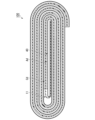
図1は、本実施形態にかかる蓄電素子の模式図である。蓄電素子200は、例えば、非水電解液二次電池、リチウムイオン二次電池である。図1では、理解を容易にするために、電極体100が外装体C内に収容される直前の状態を図示している。"First embodiment"
FIG. 1 is a schematic diagram of a power storage element according to this embodiment. The
蓄電素子200は、電極体100と外装体Cとを備える。電極体100の構造については後述する。電極体100は、電解液と共に、外装体Cの収容空間Kに収容される。電極体100は、外部との電気的な接続を担うタブt1、t2を有する。タブt1、t2は、外装体Cから外部に突出する。タブt1は、後述する第1金属層12と接続され、タブt2は、後述する第2金属層13と接続される。
The
タブt1、t2は金属を含んで構成される。金属としては、例えばアルミニウム、銅、ニッケル、SUS等である。 The tabs t1 and t2 are made of metal. Examples of the metal include aluminum, copper, nickel, and SUS.
タブt1、t2は、例えば、後述するz方向からの平面視で矩形であるが、同形状に限らず種々形状を採用可能である。 The tabs t1 and t2 are, for example, rectangular in plan view from the z direction, which will be described later, but are not limited to the same shape and may have various shapes.
外装体Cは、その内部に電極体100及び電解液を密封するものである。外装体Cは、電解液の外部への漏出や、外部からの電極体100への水分等の侵入等を抑止する。
The exterior body C seals the
外装体Cは、例えば、金属箔を高分子膜で両側からコーティングした金属ラミネートフィルムである。金属箔は例えばアルミ箔であり、高分子膜は、例えばポリプロピレン等の樹脂である。外側の高分子膜は、例えば、ポリエチレンテレフタレート(PET)、ポリアミド等であり、内側の高分子膜は、例えば、ポリエチレン(PE)、ポリプロピレン(PP)等である。熱により溶着しやすくするために、内側の高分子膜は、例えば、外側の高分子膜より融点が低い。 The exterior body C is, for example, a metal laminate film in which metal foil is coated on both sides with a polymer film. The metal foil is, for example, aluminum foil, and the polymer film is, for example, resin such as polypropylene. The outer polymer membrane is, for example, polyethylene terephthalate (PET), polyamide, etc., and the inner polymer membrane is, for example, polyethylene (PE), polypropylene (PP), etc. In order to facilitate thermal welding, the inner polymer film has, for example, a lower melting point than the outer polymer film.
外装体Cと電極体100との間には、粘着性物質を含む粘着層を有してもよい。外装体Cは、電極体100の最外面を覆う。外装体Cの内面は、電極体100の最外面と対向する。粘着層は、例えば、外装体Cの電極体100と対向する面(内面)、電極体100の外装体Cと対向する面(電極体の最外面)にある。粘着層は、例えば、電解液耐性のある両面テープ等である。粘着層は、例えば、ポリプロピレン基材にポリイソブチレンゴムの粘着層が形成されたもの、ブチルゴム等のゴム、飽和炭化水素樹脂等でもよい。粘着層は、電極体100が外装体Cの内部で動くことを抑制する。また粘着層は、釘等の金属体が刺さった場合においても、釘等の金属体に粘着性物質が纏わりつくことで、短絡を抑制する。
An adhesive layer containing an adhesive substance may be provided between the exterior body C and the
電解液は、例えば、リチウム塩等を含む非水電解液である。電解液は、非水溶媒に電解質が溶解されたものであり、非水溶媒として環状カーボネートと鎖状カーボネートとを含有してもよい。 The electrolytic solution is, for example, a non-aqueous electrolytic solution containing lithium salt or the like. The electrolytic solution is an electrolyte dissolved in a non-aqueous solvent, and may contain a cyclic carbonate and a chain carbonate as the non-aqueous solvent.
環状カーボネートは、電解質を溶媒和する。環状カーボネートは、例えば、エチレンカーボネート、プロピレンカーボネート及びブチレンカーボネートなどである。鎖状カーボネートは、環状カーボネートの粘性を低下させる。鎖状カーボネートは、例えば、ジエチルカーボネート、ジメチルカーボネート、エチルメチルカーボネートである。鎖状カーボネートとして、その他、酢酸メチル、酢酸エチル、プロピオン酸メチル、プロピオン酸エチル、プロピオン酸プロピル、γ-ブチロラクトン、1,2-ジメトキシエタン、1,2-ジエトキシエタンなどを混合して使用してもよい。環状カーボネートと鎖状カーボネートとの割合は、例えば、体積比にして1:9~1:1である。 Cyclic carbonates solvate electrolytes. Examples of cyclic carbonates include ethylene carbonate, propylene carbonate, and butylene carbonate. The chain carbonate reduces the viscosity of the cyclic carbonate. Examples of chain carbonates include diethyl carbonate, dimethyl carbonate, and ethylmethyl carbonate. Other chain carbonates that can be used include methyl acetate, ethyl acetate, methyl propionate, ethyl propionate, propyl propionate, γ-butyrolactone, 1,2-dimethoxyethane, and 1,2-diethoxyethane. You can. The ratio of the cyclic carbonate to the chain carbonate is, for example, 1:9 to 1:1 in terms of volume ratio.
非水溶媒は、例えば、環状カーボネート又は鎖状カーボネートの水素の一部がフッ素に置換されたものでもよい。非水溶媒は、例えば、フルオロエチレンカーボネート、ジフルオロエチレンカーボネート等を有してもよい。 The nonaqueous solvent may be, for example, a cyclic carbonate or a chain carbonate in which some of the hydrogen atoms are replaced with fluorine. The nonaqueous solvent may include, for example, fluoroethylene carbonate, difluoroethylene carbonate, and the like.
電解質は、例えば、LiPF6、LiClO4、LiBF4、LiCF3SO3、LiCF3CF2SO3、LiC(CF3SO2)3、LiN(CF3SO2)2、LiN(CF3CF2SO2)2、LiN(CF3SO2)(C4F9SO2)、LiN(CF3CF2CO)2、LiBOB等のリチウム塩である。これらのリチウム塩は1種を単独で使用してもよく、2種以上を併用してもよい。電離度の観点から、電解質としてLiPF6を含むことが好ましい。Examples of the electrolyte include LiPF6 , LiClO4, LiBF4 , LiCF3SO3 , LiCF3CF2SO3 , LiC ( CF3SO2 ) 3 , LiN( CF3SO2 ) 2 , LiN( CF3CF2 ) . These are lithium salts such as SO2 ) 2 , LiN( CF3SO2 ) ( C4F9SO2 ) , LiN( CF3CF2CO ) 2 , and LiBOB. These lithium salts may be used alone or in combination of two or more. From the viewpoint of the degree of ionization, it is preferable to include LiPF 6 as the electrolyte.
LiPF6を非水溶媒に溶解する際は、電解液中の電解質の濃度を、例えば、0.5mol/L以上2.0mol/L以下に調整する。電解質の濃度が0.5mol/L以上であると、非水電解液のリチウムイオン濃度を充分に確保することができ、充放電時に十分な容量が得られやすい。また、電解質の濃度を2.0mol/L以下に抑えることで、非水電解液の粘度上昇を抑え、リチウムイオンの移動度を充分に確保することができ、充放電時に十分な容量が得られやすくなる。When dissolving LiPF 6 in a nonaqueous solvent, the concentration of electrolyte in the electrolytic solution is adjusted to, for example, 0.5 mol/L or more and 2.0 mol/L or less. When the electrolyte concentration is 0.5 mol/L or more, a sufficient lithium ion concentration of the non-aqueous electrolyte can be ensured, and sufficient capacity can be easily obtained during charging and discharging. In addition, by suppressing the electrolyte concentration to 2.0 mol/L or less, it is possible to suppress the increase in viscosity of the non-aqueous electrolyte and ensure sufficient mobility of lithium ions, ensuring sufficient capacity during charging and discharging. It becomes easier.
LiPF6をその他の電解質と混合する場合にも、例えば、非水電解液中のリチウムイオン濃度が0.5mol/L以上2.0mol/L以下に調整し、LiPF6からのリチウムイオン濃度がその50mol%以上であることが好ましい。When LiPF 6 is mixed with other electrolytes, for example, the lithium ion concentration in the nonaqueous electrolyte is adjusted to 0.5 mol/L or more and 2.0 mol/L or less, and the lithium ion concentration from LiPF 6 is adjusted to that level. It is preferable that it is 50 mol% or more.
非水溶媒は、例えば、常温溶融塩を有してもよい。常温溶融塩は、カチオンとアニオンの組合せによって得られる100℃未満でも液体状の塩である。常温溶融塩は、イオンのみからなる液体であるため、静電的な相互作用が強く、不揮発性、不燃性と言う特徴を有する。 The non-aqueous solvent may include, for example, a salt molten at room temperature. A room temperature molten salt is a salt obtained by a combination of a cation and an anion that remains liquid even at a temperature below 100°C. Since room-temperature molten salt is a liquid consisting only of ions, it has strong electrostatic interactions and is nonvolatile and nonflammable.
常温溶融塩のカチオン成分としては、窒素を含む窒素系カチオン、リンを含むリン系カチオン、硫黄を含む硫黄系カチオンなどが挙げられる。これらのカチオン成分は、1種を単独で含んでいてもよいし、2種以上を組合せて含んでいてもよい。 Examples of the cation component of the room temperature molten salt include nitrogen-based cations containing nitrogen, phosphorus-based cations containing phosphorus, and sulfur-based cations containing sulfur. These cation components may contain one type alone or a combination of two or more types.
窒素系カチオンとしては、イミダゾリウムカチオン、ピロリジニウムカチオン、ピペリジニウムカチオン、ピリジニウムカチオン、アゾニアスピロカチオンなど鎖状または環状のアンモニウムカチオンが挙げられる。 Examples of nitrogen-based cations include chain or cyclic ammonium cations such as imidazolium cations, pyrrolidinium cations, piperidinium cations, pyridinium cations, and azonia spiro cations.
リン系カチオンとしては、鎖状または環状のホスホニウムカチオンが挙げられる。 Examples of phosphorus cations include chain or cyclic phosphonium cations.
硫黄系カチオンの例としては、鎖状または環状のスルホニウムカチオンが挙げられる。 Examples of sulfur-based cations include chain or cyclic sulfonium cations.
カチオン成分としては、特に、リチウムイミド塩を溶解させた際に、高いリチウムイオン伝導を有し、かつ広い酸化還元耐性をもつため、窒素系カチオンであるN-メチル-N-プロピル-ピロリジニウム(P13)が好ましい。 As a cation component, the nitrogen-based cation N-methyl-N-propyl-pyrrolidinium (P13 ) is preferred.
常温溶融塩のアニオン成分としては、AlCl4 -、NO2 -、NO3 -、I-、BF4 -、PF6 -、AsF6 -、SbF6 -、NbF6 -、TaF6 -、F(HF)2.3 -、p-CH3PhSO3 -、CH3CO2 -、CF3CO2 -、CH3SO3 -、CF3SO3 -、(CF3SO2)3C-、C3F7CO2 -、C4F9SO3 -、(FSO2)2N-(ビス(フルオロスルホニル)イミド:FSI)、(CF3SO2)2N-(ビス(トリフルオロメタンスルホニル)イミド:TFSI)、(C2F5SO2)2N-(ビス(ペンタフルオロエタンスルホニル)イミド)、(CF3SO2)(CF3CO)N-((トリフルオロメタンスルホニル)(トリフルオロメタンカルボニル)イミド)、(CN)2N-(ジシアノイミド)等が挙げられる。これらのアニオン成分は、1種を単独で含んでいてもよいし、2種以上を組合せて含んでいてもよい。The anion components of the room temperature molten salt include AlCl 4 − , NO 2 − , NO 3 − , I − , BF 4 − , PF 6 − , AsF 6 − , SbF 6 − , NbF 6 − , TaF 6 − , F( HF) 2.3 - , p-CH 3 PhSO 3 - , CH 3 CO 2 - , CF 3 CO 2 - , CH 3 SO 3 - , CF 3 SO 3 - , (CF 3 SO 2 ) 3 C - , C 3 F 7 CO 2 − , C 4 F 9 SO 3 − , (FSO 2 ) 2 N − (bis(fluorosulfonyl)imide: FSI), (CF 3 SO 2 ) 2 N − (bis(trifluoromethanesulfonyl) imide) :TFSI), (C 2 F 5 SO 2 ) 2 N - (bis(pentafluoroethanesulfonyl)imide), (CF 3 SO 2 ) (CF 3 CO) N - ((trifluoromethanesulfonyl) (trifluoromethane carbonyl) imide), (CN) 2 N - (dicyanoimide), and the like. These anion components may contain one type alone or a combination of two or more types.
図2は、第1実施形態にかかる電極体100の断面図である。図2は、電極体100の巻軸方向と直交する電極体100の断面である。電極体100は、電池シートが第1端を軸に巻回されたものである。電池シートは、樹脂層11と正極Cdと負極Adとセパレータ40とを有する。電極体100は、例えば、セパレータ40、負極Ad、樹脂層11、正極Cdの順に、巻き内側から巻き外側に向かって、繰り返す。負極Adは、例えば、正極Cdより巻き内側にある。負極Adが巻き内側にあると、蓄電素子200のエネルギー密度が高まる。
FIG. 2 is a cross-sectional view of the
図3は、第1実施形態にかかる電極体100を展開した電池シートSの集電体10の第1端の断面図である。第1端は、電極体100の巻き内側となる端部である。図4は、第1実施形態にかかる電極体100を展開した電池シートSの集電体の両面をそれぞれ平面視した図である。図5は、第1実施形態にかかる電極体100を展開した電池シートSの集電体の別の断面図である。
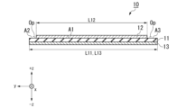
FIG. 3 is a sectional view of the first end of the
ここで方向について定義する。電池シートSの各層の積層方向をz方向とする。第2金属層13から第1金属層12へ向かう方向を+z方向、+z方向と反対の方向を-z方向とする。電池シートSの広がる面内の一方向をx方向とし、x方向と直交する方向をy方向とする。図3は、電池シートSのxz断面(図4のA-A線に沿った断面)であり、図5は集電体10のyz断面(図4のB-B線に沿った断面)である。
Here we define the direction. The stacking direction of each layer of the battery sheet S is defined as the z direction. The direction from the
電池シートSは、集電体10と正極活物質層20と負極活物質層30とセパレータ40とを有する。正極活物質層20は、集電体10の第1面10a側に形成されている。負極活物質層30は、集電体10の第2面10b側に形成されている。第2面10bは、集電体10において、第1面10aの反対側の面である。集電体10は、第1面10aと、第1面10とは反対側を向く第2面10bと、を有する。正極活物質層20は、第1活物質層の一例である。負極活物質層30は、第2活物質層の一例である。セパレータ40は、正極活物質層20又は負極活物質層30に接する。セパレータ40は、電極体100が巻回された状態において、正極活物質層20と負極活物質層30との間にある。
The battery sheet S includes a
集電体10は、樹脂層11と第1金属層12と第2金属層13とを有する。第1金属層12は、樹脂層11の第1面11a側に形成されている。第2金属層13は、樹脂層11の第2面11b側に形成されている。第2面11bは、樹脂層11において第1面11aと反対側の面である。第1金属層12は、例えば、正極集電体である。第2金属層13は、例えば、負極集電体である。例えば、第1金属層12の樹脂層11と反対側の面に正極活物質層20が形成されている。この場合、第1金属層12と正極活物質層20とで正極Cdとなる。例えば、第2金属層13の樹脂層11と反対側の面に負極活物質層30が形成されている。この場合、第2金属層13と負極活物質層30とで負極Adとなる。第1金属層12と第2金属層13との関係が反対であり、第1金属層12が負極集電体で、第2金属層13が正極集電体でもよい。第1金属層12、第2金属層13は、導電層であればよい。
樹脂層11の第1面11aは、第1領域A1と第2領域A2と第3領域A3とを有する。第1領域A1は、第1面11aにおいて第1金属層12が積層されている領域であり、z方向視において、第1金属層12と第1表面11aとが重なる領域である。第2領域A2は、第1面11aにおいて、第1金属層12と離間する領域であり、第1領域A1のy方向の側方にある。第3領域A3は、第1面11aにおいて、第1金属層12と離間する領域であり、第1領域A1の第2領域A2と反対側のy方向の側方にある。第2領域A2と第3領域A3とは、第1領域をy方向に挟む。第2領域A2及び第3領域A3上には、例えば、開口Opがある。第2領域A2及び第3領域A3において第1面11aが第1金属層12から露出している。
The
樹脂層11と第1金属層12とは、x方向における長さが、一致していてもよく、異なっていてもよい。樹脂層11のx方向の端辺と第1金属層12のx方向の端辺の位置は、一致していても異なっていてもよい。樹脂層11のx方向における長さは、第1金属層12のx方向における長さよりも、長いことが好ましい。
The lengths of the
また、第1金属層12のx方向における長さと、第2金属層13のx方向における長さとは、一致していてもよく、異なっていてもよい。第1金属層12のx方向における長さは、第2金属層13のx方向における長さより長いことが好ましい。
Furthermore, the length of the
第1金属層12は、y方向において、樹脂層11の第1面11aを被覆する。第1金属層12のy方向の長さL12は、樹脂層11のy方向の長さL11より短い。
The
第2金属層13は、y方向において、樹脂層11の第2面11bの全面を被覆する。第2金属層13のy方向の長さL13は、樹脂層11のy方向の長さL11と一致する。第1金属層12のy方向の長さL12は、第2金属層13のy方向の長さL13より短い。
The
なお、第2金属層13のy方向の長さL13が樹脂層11のy方向の長さL11と一致する、とは、樹脂層11のy方向における長さL11と第2金属層13のy方向における長さL13との差が3%以内であることを指す。
Note that the length L13 of the
樹脂層11は、絶縁性を有する材料を含んで構成されている。本明細書において、絶縁性とは、抵抗値が1.0×10⁹Ω・cm以上を意味する。樹脂層11は、例えば、絶縁層である。樹脂層11は、第1層の一例である。樹脂層11は、ポリエチレンテレフタレート(PET)、ポリイミド(PI)、ポリアミドイミド(PAI)、ポリプロピレン(PP)、ポリエチレン(PE)、からなる群から選択されるいずれかを含む。樹脂層11は、例えば、PETフィルムである。樹脂層11は、第1金属層12と第2金属層13との間を絶縁する。樹脂層11の厚みは、例えば、3μm以上9μm以下であり、好ましくは4μm以上6μm以下である。The
第1金属層12と第2金属層13とは、それぞれ、アルミニウム、ニッケル、ステンレス鋼、銅、白金、金から選択されるいずれかである。第1金属層12と第2金属層13とは、例えば、異なる金属又は合金を含む。第1金属層12は、例えば、アルミニウムであり、第2金属層13は、例えば、銅である。第1金属層12と第2金属層13とは、同じ材質からなってもよい。例えば、第1金属層12と第2金属層13は、いずれもアルミニウムである。
The
第1金属層12と第2金属層13とは、両方ともがアルミニウムである構成、または第1金属層12と第2金属層13とのうち一方がアルミニウムで他方が銅である構成が好ましい。
It is preferable that the
第1金属層12と第2金属層13との厚みは同じであってもよく、違っていてもよい。第1金属層12と第2金属層13の厚みは、例えば、0.3μm以上2μm以下であることが好ましく、0.4μm以上1μm以下であることが好ましい。
The thickness of the
正極活物質層20は、例えば、正極活物質と導電助剤とバインダーとを有する。
The positive electrode
正極活物質は、リチウムイオンの吸蔵及び放出、リチウムイオンの脱離及び挿入(インターカレーション)、又は、リチウムイオンとカウンターアニオンのドープ及び脱ドープを可逆的に進行させることができる。 The positive electrode active material is capable of reversibly occluding and deintercalating lithium ions, deintercalating and intercalating lithium ions, or doping and dedoping lithium ions and counter anions.
正極活物質は、例えば、コバルト酸リチウム(LiCoO2)、ニッケル酸リチウム(LiNiO2)、マンガン酸リチウム(LiMnO2)、リチウムマンガンスピネル(LiMn2O4)、及び、一般式:LiNixCoyMnzMaO2(x+y+z+a=1、0≦x<1、0≦y<1、0≦z<1、0≦a<1、MはAl、Mg、Nb、Ti、Cu、Zn、Crより選ばれる1種類以上の元素)で表される複合金属酸化物、リチウムバナジウム化合物(LiV2O5)、オリビン型LiMPO4(ただし、Mは、Co、Ni、Mn、Fe、Mg、Nb、Ti、Al、Zrより選ばれる1種類以上の元素又はVOを示す)、チタン酸リチウム(Li4Ti5O12)、LiNixCoyAlzO2(0.9<x+y+z<1.1)等の複合金属酸化物、ポリアセチレン、ポリアニリン、ポリピロール、ポリチオフェン、ポリアセンなどである。また正極活物質は、これらを混合したものでもよい。Examples of the positive electrode active material include lithium cobalt oxide (LiCoO 2 ), lithium nickel oxide (LiNiO 2 ), lithium manganate (LiMnO 2 ), lithium manganese spinel (LiMn 2 O 4 ), and general formula: LiNix Co y Mn z M a O 2 (x+y+z+a=1, 0≦x<1, 0≦y<1, 0≦z<1, 0≦a<1, M is Al, Mg, Nb, Ti, Cu, Zn, Cr complex metal oxides, lithium vanadium compounds (LiV 2 O 5 ), olivine-type LiMPO 4 (where M is Co, Ni, Mn, Fe, Mg, Nb, one or more elements selected from Ti, Al, Zr or VO), lithium titanate (Li 4 Ti 5 O 12 ), LiNix Co y Al z O 2 (0.9<x+y+z<1.1) etc., polyacetylene, polyaniline, polypyrrole, polythiophene, polyacene, etc. Further, the positive electrode active material may be a mixture of these materials.
導電助材は、正極活物質層内に点在している。導電助材は、正極活物質層における正極活物質の間の導電性を高める。導電助材は、例えば、カーボンブラック類等のカーボン粉末、カーボンナノチューブ、炭素材料、銅、ニッケル、ステンレス、鉄等の金属微粉、炭素材料及び金属微粉の混合物、ITO等の導電性酸化物である。導電助材は、カーボンブラック等の炭素材料が好ましい。活物質で十分な導電性を確保できる場合は、正極活物質層20は導電助材を含まなくてもよい。
The conductive support material is scattered within the positive electrode active material layer. The conductive additive increases the conductivity between the positive electrode active materials in the positive electrode active material layer. Examples of the conductive additive include carbon powder such as carbon black, carbon nanotubes, carbon materials, fine metal powder such as copper, nickel, stainless steel, and iron, a mixture of carbon materials and fine metal powder, and conductive oxides such as ITO. . The conductive auxiliary material is preferably a carbon material such as carbon black. If sufficient conductivity can be ensured with the active material, the positive electrode
バインダーは、正極活物質層における正極活物質同士を結合する。バインダーは、公知のものを用いることができる。バインダーは、例えば、フッ素樹脂である。フッ素樹脂は、例えば、ポリフッ化ビニリデン(PVDF)、ポリテトラフルオロエチレン(PTFE)、テトラフルオロエチレン-ヘキサフルオロプロピレン共重合体(FEP)、テトラフルオロエチレン-パーフルオロアルキルビニルエーテル共重合体(PFA)、エチレン-テトラフルオロエチレン共重合体(ETFE)、ポリクロロトリフルオロエチレン(PCTFE)、エチレン-クロロトリフルオロエチレン共重合体(ECTFE)、ポリフッ化ビニル(PVF)等である。 The binder binds the positive electrode active materials in the positive electrode active material layer. A known binder can be used. The binder is, for example, a fluororesin. Examples of the fluororesin include polyvinylidene fluoride (PVDF), polytetrafluoroethylene (PTFE), tetrafluoroethylene-hexafluoropropylene copolymer (FEP), tetrafluoroethylene-perfluoroalkyl vinyl ether copolymer (PFA), These include ethylene-tetrafluoroethylene copolymer (ETFE), polychlorotrifluoroethylene (PCTFE), ethylene-chlorotrifluoroethylene copolymer (ECTFE), and polyvinyl fluoride (PVF).
上記の他に、バインダーは、例えば、ビニリデンフルオライド-ヘキサフルオロプロピレン系フッ素ゴム(VDF-HFP系フッ素ゴム)、ビニリデンフルオライド-ヘキサフルオロプロピレン-テトラフルオロエチレン系フッ素ゴム(VDF-HFP-TFE系フッ素ゴム)、ビニリデンフルオライド-ペンタフルオロプロピレン系フッ素ゴム(VDF-PFP系フッ素ゴム)、ビニリデンフルオライド-ペンタフルオロプロピレン-テトラフルオロエチレン系フッ素ゴム(VDF-PFP-TFE系フッ素ゴム)、ビニリデンフルオライド-パーフルオロメチルビニルエーテル-テトラフルオロエチレン系フッ素ゴム(VDF-PFMVE-TFE系フッ素ゴム)、ビニリデンフルオライド-クロロトリフルオロエチレン系フッ素ゴム(VDF-CTFE系フッ素ゴム)等のビニリデンフルオライド系フッ素ゴムでもよい。 In addition to the above, binders include, for example, vinylidene fluoride-hexafluoropropylene-based fluororubber (VDF-HFP-based fluororubber), vinylidene fluoride-hexafluoropropylene-tetrafluoroethylene-based fluororubber (VDF-HFP-TFE-based fluororubber), (fluororubber), vinylidene fluoride-pentafluoropropylene-based fluororubber (VDF-PFP-based fluororubber), vinylidene fluoride-pentafluoropropylene-tetrafluoroethylene-based fluororubber (VDF-PFP-TFE-based fluororubber), vinylidene fluoride Vinylidene fluoride fluorine rubber such as Ride-perfluoromethyl vinyl ether-tetrafluoroethylene fluorine rubber (VDF-PFMVE-TFE fluorine rubber), vinylidene fluoride-chlorotrifluoroethylene fluorine rubber (VDF-CTFE fluorine rubber), etc. It can also be made of rubber.
負極活物質層30は、負極活物質を含む。また必要に応じて、導電助材、バインダー、固体電解質を含んでもよい。
The negative electrode
負極活物質は、イオンを吸蔵・放出可能な化合物であればよく、公知のリチウムイオン二次電池に用いられる負極活物質を使用できる。負極活物質は、例えば、金属リチウム、リチウム合金、イオンを吸蔵・放出可能な黒鉛(天然黒鉛、人造黒鉛)、カーボンナノチューブ、難黒鉛化炭素、易黒鉛化炭素、低温度焼成炭素等の炭素材料、アルミニウム、シリコン、スズ、ゲルマニウム等のリチウム等の金属と化合することのできる半金属または金属、SiOx(0<x<2)、二酸化スズ等の酸化物を主体とする非晶質の化合物、チタン酸リチウム(Li4Ti5O12)等を含む粒子である。The negative electrode active material may be any compound that can absorb and release ions, and negative electrode active materials used in known lithium ion secondary batteries can be used. Examples of negative electrode active materials include carbon materials such as metallic lithium, lithium alloys, graphite (natural graphite, artificial graphite) capable of intercalating and releasing ions, carbon nanotubes, non-graphitizable carbon, easily graphitizable carbon, and low-temperature calcined carbon. , semimetals or metals that can be combined with metals such as lithium, such as aluminum, silicon, tin, germanium, etc., amorphous compounds mainly composed of oxides such as SiO x (0<x<2), and tin dioxide. , lithium titanate (Li 4 Ti 5 O 12 ), and the like.
負極活物質層30は、上述のように例えば、シリコン、スズ、ゲルマニウムを含んでもよい。シリコン、スズ、ゲルマニウムは、単体元素として存在してもよいし、化合物として存在してもよい。化合物は、例えば、合金、酸化物等である。一例として、負極活物質がシリコンの場合、負極はSi負極と呼ばれることがある。負極活物質は、例えば、シリコン、スズ、ゲルマニウムの単体又は化合物と炭素材との混合系でもよい。炭素材は、例えば天然黒鉛である。また負極活物質は、例えば、シリコン、スズ、ゲルマニウムの単体又は化合物の表面が炭素で被覆されたものでもよい。炭素材及び被覆された炭素は、負極活物質と導電助材との間の導電性を高める。負極活物質層がシリコン、スズ、ゲルマニウムを含むと、蓄電素子200の容量が大きくなる。
The negative electrode
負極活物質層30は、上述のように例えば、リチウムを含んでもよい。リチウムは、金属リチウムでもリチウム合金でもよい。負極活物質層30は、金属リチウム又はリチウム合金でもよい。リチウム合金は、例えば、Si、Sn、C、Pt、Ir、Ni、Cu、Ti、Na、K、Rb、Cs、Fr、Be、Mg、Ca、Sr、Sb、Pb、In、Zn、Ba、Ra、Ge、Alからなる群から選択される1種以上の元素と、リチウムと、の合金である。一例として、負極活物質が金属リチウムの場合、負極はLi負極と呼ばれることがある。負極活物質層30は、リチウムのシートでもよい。
The negative electrode
負極は、作製時に負極活物質層30を有さずに、負極集電体(第2金属層13)のみであってもよい。蓄電素子200を充電すると、負極集電体の表面に金属リチウムが析出する。金属リチウムはリチウムイオンが析出した単体のリチウムであり、金属リチウムは負極活物質層として機能する。
The negative electrode may include only the negative electrode current collector (second metal layer 13) without having the negative electrode
導電助材及びバインダーは、正極活物質層20と同様のものを用いることができる。負極活物質層30におけるバインダーは、正極活物質層20に挙げたものの他に、例えば、セルロース、スチレン・ブタジエンゴム、エチレン・プロピレンゴム、ポリイミド樹脂、ポリアミドイミド樹脂、アクリル樹脂等でもよい。セルロースは、例えば、カルボキシメチルセルロース(CMC)でもよい。
The same conductive material and binder as those used in the positive electrode
セパレータ40は、例えば、電気絶縁性の多孔質構造を有する。セパレータ40は、例えば、ポリエチレン又はポリプロピレン等のポリオレフィンからなるフィルムの単層体、積層体や上記樹脂の混合物の延伸膜、或いはセルロース、ポリエステル、ポリアクリロニトリル、ポリアミド、ポリエチレン及びポリプロピレンからなる群より選択される少なくとも1種の構成材料からなる繊維不織布が挙げられる。
The
セパレータ40に変えて、固体電解質層を設けてもよい。固体電解質層を用いる場合は、電解液が不要となる。固体電解質層とセパレータ40とを併用してもよい。
Instead of the
固体電解質は、例えば、イオン電導度が1.0×10-8S/cm以上1.0×10-2S/cm以下のイオン導電膜である。固体電解質は、例えば、高分子固体電解質、酸化物系固体電解質、硫化物系固体電解質である。高分子固体電解質は、例えば、ポリエチレンオキサイド系高分子にアルカリ金属塩を溶解させたものである。酸化物系固体電解質は、例えば、Li1.3Al0.3Ti1.7(PO4)3(ナシコン型)、Li1.07Al0.69Ti1.46(PO4)3(ガラスセラミックス)、Li0.34La0.51TiO2.94(ペロブスカイト型)、Li7La3Zr2O12(ガーネット型)、Li2.9PO3.3N0.46(アモルファス、LIPON)、50Li4SiO4・50Li2BO3(ガラス)、90Li3BO3・10Li2SO4(ガラスセラミックス)である。硫化物系固体電解質は、例えば、Li3.25Ge0.25P0.75S4(結晶)、Li10GeP2S12(結晶、LGPS)、Li6PS5Cl(結晶、アルジロダイト型)、Li9.54Si1.74P1.44S11.7Cl0.3(結晶)、Li3.25P0.95S4(ガラスセラミックス)、Li7P3S11(ガラスセラミックス)、70Li2S・30P2S5(ガラス)、30Li2S・26B2S3・44LiI(ガラス)、50Li2S・17P2S5・33LiBH4(ガラス)、63Li2S・36SiS2・Li3PO4(ガラス)、57Li2S・38SiS2・5Li4SiO4(ガラス)である。The solid electrolyte is, for example, an ion conductive film having an ionic conductivity of 1.0×10 −8 S/cm or more and 1.0×10 −2 S/cm or less. The solid electrolyte is, for example, a polymer solid electrolyte, an oxide solid electrolyte, or a sulfide solid electrolyte. The solid polymer electrolyte is, for example, a polyethylene oxide polymer in which an alkali metal salt is dissolved. Examples of oxide-based solid electrolytes include Li 1.3 Al 0.3 Ti 1.7 (PO 4 ) 3 (Nashicon type), Li 1.07 Al 0.69 Ti 1.46 (PO 4 ) 3 (glass Ceramics), Li 0.34 La 0.51 TiO 2.94 (perovskite type), Li 7 La 3 Zr 2 O 12 (garnet type), Li 2.9 PO 3.3 N 0.46 (amorphous, LIPON) , 50Li 4 SiO 4 .50Li 2 BO 3 (glass), and 90Li 3 BO 3 .10Li 2 SO 4 (glass ceramics). Sulfide-based solid electrolytes include, for example, Li 3.25 Ge 0.25 P 0.75 S 4 (crystal), Li 10 GeP 2 S 12 (crystal, LGPS), Li 6 PS 5 Cl (crystal, argyrodite type) , Li 9.54 Si 1.74 P 1.44 S 11.7 Cl 0.3 (crystal), Li 3.25 P 0.95 S 4 (glass ceramics), Li 7 P 3 S 11 (glass ceramics) , 70Li 2 S・30P 2 S 5 (glass), 30Li 2 S・26B 2 S 3・44LiI (glass), 50Li 2 S・17P 2 S 5・33LiBH 4 (glass), 63Li 2 S・36SiS 2・Li 3PO 4 (glass ) , 57Li 2 S.38SiS 2.5Li 4 SiO 4 (glass).
次いで、蓄電素子の製造方法について説明する。まず、市販の樹脂フィルムの両面に第1金属層12と第2金属層13とを形成する。第1金属層12及び第2金属層13は、例えば、スパッタリング法、化学気相成長法(CVD法)等で成膜できる。第1金属層12は、例えば、マスク等を利用して、樹脂フィルムのy方向の両端部を除いて成膜する。樹脂フィルムの一面に第1金属層12を積層後に、両端部をエッチング等により除去してもよい。
Next, a method for manufacturing a power storage element will be described. First, a
次いで、第1金属層12の表面に、正極スラリーを塗布する。正極スラリーは、正極活物質、バインダー及び溶媒を混合して、ペースト化したものである。正極スラリーは、例えば、スリットダイコート法、ドクターブレード法等で塗布できる。
Next, a positive electrode slurry is applied to the surface of the
塗布後の正極スラリー中の溶媒を除去する。除去方法は特に限定されない。例えば、正極スラリーが塗布された集電体10を、80℃~150℃の雰囲気下で乾燥させる。次いで、得られた塗膜をプレスして、正極活物質層20を高密度化する。プレスの手段は、例えばロールプレス機、静水圧プレス機等を用いることができる。
The solvent in the positive electrode slurry after coating is removed. The removal method is not particularly limited. For example, the
次いで、正極スラリーを塗布した面と反対側の第2金属層13の表面に、負極スラリーを塗布する。負極スラリーは負極活物質、バインダー及び溶媒を混合して、ペースト化したものである。負極スラリーは、正極スラリーと同様の方法で塗布できる。塗布後の負極スラリー中の溶媒は、乾燥により除去され、負極活物質層30となる。負極活物質が金属リチウムの場合は、第2金属層13にリチウム箔を貼り付けてもよい。
Next, a negative electrode slurry is applied to the surface of the
次いで、正極活物質層20及び負極活物質層30の一部を除去し、第1金属層12にタブt1を、第2金属層13にタブt2を接合する。タブt1、t2は、例えば、超音波により金属層と溶着される。タブt1、t2は、金属層に接着してもよいし、ねじ止めしてもよいし、熱等により溶着してもよい。
Next, a portion of the positive electrode
次いで、正極活物質層20又は負極活物質層30と接する位置にセパレータ40を設け、一端側を軸として巻回する。その後、電極体100を電解液と共に、外装体C内に封入する。封入は、減圧、加熱しながら行うことで、電極体100の内部まで、電解液が含侵する。外装体Cを熱等で封止すると、蓄電素子200が得られる。
Next, a
第1実施形態にかかる電極体100は、樹脂層11の第1面11aの両端部に開口Opを有する。電極体100において、第1金属層12及び正極活物質層20は、第2金属層13及び負極活物質層30より開口Op分だけ巻き軸方向(展開体におけるy方向)の内側にある。そのため、例えば、電極体100を巻回する際に巻きずれが生じる等の要因により巻回する電池シートSの端部の位置にずれが生じた場合においても、正極Cdと負極Adとが短絡することを抑制することができる。
The
「第2実施形態」
図6は、第2実施形態にかかる電極体を展開した電池シートの集電体10Aの断面図である。図6は、集電体10Aのyz断面である。“Second embodiment”
FIG. 6 is a cross-sectional view of a
第2実施形態にかかる集電体10Aは、絶縁層14を有する点が、第1実施形態にかかる集電体10と異なる。第2実施形態にかかる蓄電素子において、第1実施形態にかかる蓄電素子200と同様の構成については、説明を省く。
A
絶縁層14は、第2領域A2と第3領域A3とのうち少なくとも一方を被覆する。絶縁層14は、例えば、第2領域A2及び第3領域A3上にある。図6に示す第2領域A2及び第3領域A3は、絶縁層14で被覆されている。絶縁層14は、セラミックスを主成分とする絶縁体を含む。セラミックスは、例えば、チタン酸バリウム、酸化アルミニウム、酸化チタンである。絶縁層14は、正極活物質層20のy方向の側方にあってもよい。
The insulating
第2実施形態にかかる電極体は、樹脂層11の第1面11aの両端部に絶縁層14を有する。電極体において、第1金属層12及び正極活物質層20は、第2金属層13及び負極活物質層30より絶縁層14の分だけ巻き軸方向(展開体におけるy方向)の内側にあり、第1金属層12の側面は絶縁層14で被覆されている。そのため、例えば、電極体を巻回する際に巻きずれが生じる等の要因により巻回する電池シートの端部の位置にずれが生じた場合においても、正極Cdと負極Adとが短絡することを抑制することができる。
The electrode body according to the second embodiment has an insulating
第1実施形態及び第2実施形態では、第2領域A2と第3領域A3のy方向の幅が同じ場合を例に説明したが、第2領域A2と第3領域A3のy方向の幅は異なってもよい。図7は、図5の変形例であり、第2領域A2と第3領域A3との幅が異なる。 In the first and second embodiments, the case where the second area A2 and the third area A3 have the same width in the y direction is explained as an example, but the width in the y direction of the second area A2 and the third area A3 is May be different. FIG. 7 is a modification of FIG. 5, in which the second area A2 and the third area A3 have different widths.
「第3実施形態」
図8は、第3実施形態に係る蓄電素子の電極体110の断面図である。第3実施形態にかかる蓄電素子は、電極体100が巻回体から積層体に置き換わっている点が異なる。“Third embodiment”
FIG. 8 is a cross-sectional view of an
電極体110は、複数の電池シートS2が積層されている。電池シートS2は、それぞれ、セパレータ40、負極活物質層30、集電体10、正極活物質層20を有する。セパレータ40、負極活物質層30、集電体10、正極活物質層20の構成は、第1実施形態にかかる電池シートSと同様である。
In the
第1金属層12は、例えば、樹脂層11の第1面を被覆する。第1金属層12のx方向及びy方向の長さは、樹脂層11のx方向及びy方向の長さより短い。
The
第2金属層13は、例えば、x方向及びy方向において、樹脂層11の第2面の全面を被覆する。第2金属層13のx方向及びy方向の長さは、樹脂層11のx方向及びy方向の長さと一致する。そのため、第1金属層12のx方向及びy方向の長さは、第2金属層13のx方向及びy方向の長さより短い。
The
第3実施形態にかかる電極体110は、樹脂層11の第1面11aの周辺部に開口Opを有する。電極体110において、第1金属層12及び正極活物質層20は、第2金属層13及び負極活物質層30より中心線Cに向かってx方向の内側にある。そのため、例えば、電極体110を積層する際に、x方向に各層の位置にずれが生じた場合においても、正極Cdと負極Adとが短絡することを抑制することができる。
The
以上、本発明の実施形態について図面を参照して詳述したが、各実施形態における各構成及びそれらの組み合わせ等は一例であり、本発明の趣旨から逸脱しない範囲内で、構成の付加、省略、置換、及びその他の変更が可能である。 The embodiments of the present invention have been described above in detail with reference to the drawings, but each configuration and combination thereof in each embodiment is merely an example, and additions or omissions of configurations may be made within the scope of the spirit of the present invention. , substitutions, and other changes are possible.
「実施例1」
(集電体の作製)
まず樹脂層として、厚さ6.0μmのPETフィルムを長さ100mm、幅10mmに切り出した。次いで、樹脂層の第1面に、第1金属層として、厚み1.0μmのアルミニウムを積層した。樹脂層のy方向の両端から20mmの範囲には、アルミニウムを積層しなかった。次いで、樹脂層の第2面に、第2金属層として、厚み1.0μmの銅を積層した。第2金属層は、樹脂層の第2面の全面に積層した。"Example 1"
(Preparation of current collector)
First, a PET film with a thickness of 6.0 μm was cut out to a length of 100 mm and a width of 10 mm as a resin layer. Next, aluminum having a thickness of 1.0 μm was laminated as a first metal layer on the first surface of the resin layer. Aluminum was not laminated within a range of 20 mm from both ends of the resin layer in the y direction. Next, copper with a thickness of 1.0 μm was laminated as a second metal layer on the second surface of the resin layer. The second metal layer was laminated on the entire second surface of the resin layer.
(正極活物質層の作製)
正極活物質には、コバルト酸リチウム(LiCoO2)を用いた。この正極活物質を1.90質量部と、アセチレンブラックを5質量部と、ポリフッ化ビニリデン(PVDF)を5質量部と、をN-メチル-2-ピロリドン(NMP)中に分散させ、スラリーを調製した。得られたスラリーをPETフィルムのアルミニウムが積層されている部分に塗布した。その後、温度140℃で30分間乾燥した。その後、ロールプレス装置を用いてプレス処理し正極活物質層を得た。(Preparation of positive electrode active material layer)
Lithium cobalt oxide (LiCoO 2 ) was used as the positive electrode active material. 1.90 parts by mass of this positive electrode active material, 5 parts by mass of acetylene black, and 5 parts by mass of polyvinylidene fluoride (PVDF) were dispersed in N-methyl-2-pyrrolidone (NMP) to form a slurry. Prepared. The obtained slurry was applied to the portion of the PET film where aluminum was laminated. Thereafter, it was dried at a temperature of 140° C. for 30 minutes. Thereafter, a positive electrode active material layer was obtained by pressing using a roll press device.
(負極活物質層の作製)
天然黒鉛粉末(負極活物質)を90質量部と、PVDFを10質量部とを、NMP中に分散させてスラリーを調製した。得られたスラリーをPETフィルムの銅が積層されている部分に塗布した。その後温度140℃で30分間減圧乾燥した。その後、ロールプレス装置を用いてプレス処理し負極活物質層を得た。(Preparation of negative electrode active material layer)
A slurry was prepared by dispersing 90 parts by mass of natural graphite powder (negative electrode active material) and 10 parts by mass of PVDF in NMP. The obtained slurry was applied to the part of the PET film where copper was laminated. Thereafter, it was dried under reduced pressure at a temperature of 140° C. for 30 minutes. Thereafter, a negative electrode active material layer was obtained by pressing using a roll press device.
(セパレータの準備)
膜厚20μmのポリエチレン微多孔膜(空孔率:40%、シャットダウン温度:134℃)を用意した。(Preparation of separator)
A microporous polyethylene membrane (porosity: 40%, shutdown temperature: 134° C.) with a thickness of 20 μm was prepared.
(電極体の作製)
正極活物質層及び負極活物質層の一部を、メチルエチルケトン(MEK)を染み込ませた綿棒で擦り剥がし、タブを接続した。次いで、セパレータを電池シートの一面に重ね、樹脂層の第1端を軸として巻回して電極体を作製した。(Preparation of electrode body)
Parts of the positive electrode active material layer and the negative electrode active material layer were rubbed off with a cotton swab impregnated with methyl ethyl ketone (MEK), and the tabs were connected. Next, a separator was placed on one side of the battery sheet, and the separator was wound around the first end of the resin layer as an axis to produce an electrode body.
(電解液)
電解質としてエチレンカーボネート(EC)とジエチルカーボネート(DEC)の混合溶媒に、LiPF6を1.0mol/Lとなるように溶解させた非水電解質溶液を用意した。混合溶媒におけるECとDECとの体積比は、EC:DEC=30:70とした。(electrolyte)
A non-aqueous electrolyte solution was prepared in which LiPF 6 was dissolved at 1.0 mol/L in a mixed solvent of ethylene carbonate (EC) and diethyl carbonate (DEC) as an electrolyte. The volume ratio of EC and DEC in the mixed solvent was EC:DEC=30:70.
(電池の作製)
電極体を非水電解液と共にアルミラミネートに封入し、実施例1の電池セルを作製した。(Preparation of battery)
The battery cell of Example 1 was produced by encapsulating the electrode body together with a non-aqueous electrolyte in an aluminum laminate.
同条件で10サンプルを作製し、正極と負極とが短絡していないかを確認した。実施例1にかかる蓄電素子は、10サンプル中で、短絡したものはなかった。 Ten samples were prepared under the same conditions, and it was confirmed whether the positive electrode and the negative electrode were short-circuited. Among the 10 samples of the electricity storage elements according to Example 1, none were short-circuited.
「実施例2」
実施例2は、樹脂層のy方向の両端から1.0mmの範囲には、アルミニウムを積層せず、その部分にセラミック層を設けた点が、実施例1と異なる。セラミック層の主成分は、アルミナ(Al2O3)とした。"Example 2"
Example 2 differs from Example 1 in that aluminum is not laminated within a range of 1.0 mm from both ends of the resin layer in the y direction, and a ceramic layer is provided in that area. The main component of the ceramic layer was alumina (Al 2 O 3 ).
実施例2も実施例1と同様に、同条件の10サンプルを作製し、正極と負極とが短絡していないかを確認した。実施例2にかかる蓄電素子は、10サンプル中で、短絡したものはなかった。 In Example 2, 10 samples were prepared under the same conditions as in Example 1, and it was confirmed whether the positive electrode and the negative electrode were short-circuited. Among the 10 samples of the electricity storage elements according to Example 2, none were short-circuited.
「比較例1」
比較例1は、樹脂層のy方向の両端から20mmの範囲にもアルミニウムを積層し、第1金属層を樹脂層の第2面の全面に積層した。実比較例1も実施例1と同様に、同条件の10サンプルを作製し、正極と負極とが短絡していないかを確認した。比較例1にかかる蓄電素子は、10サンプル中、6サンプルが短絡した。“Comparative Example 1”
In Comparative Example 1, aluminum was also laminated within a range of 20 mm from both ends of the resin layer in the y direction, and the first metal layer was laminated over the entire second surface of the resin layer. In Comparative Example 1, 10 samples were prepared under the same conditions as in Example 1, and it was confirmed whether the positive electrode and the negative electrode were short-circuited. In the electricity storage device according to Comparative Example 1, 6 out of 10 samples were short-circuited.
樹脂層の第1面の両端部に、開口又は絶縁層を有する実施例1、2は短絡がなかったのに対し、比較例1は一部のサンプルが短絡した。 In Examples 1 and 2, which had openings or insulating layers at both ends of the first surface of the resin layer, there was no short circuit, whereas in Comparative Example 1, some samples had short circuits.
10 集電体
11 樹脂層
12 第1金属層
13 第2金属層
14 絶縁層
20 正極活物質層
30 負極活物質層
40 セパレータ
100、110 電極体
200 蓄電素子
A1 第1領域
A2 第2領域
A3 第3領域
Ad 負極
Cd 正極
C 外装体
K 収容空間
Op 開口
S1、S2 電池シート
t1、t2 タブ10
Claims (8)
前記第1金属層に積層された第1活物質層と、
前記第2金属層に積層された第2活物質層と、
前記第1活物質層と前記第2活物質層とのうちの少なくとも一方と接するセパレータ又は固体電解質層と、
絶縁層と、を有し、
前記第1層の前記第1面は、前記第1金属層が積層された第1領域と、前記第1金属層の積層方向から見て前記第1金属層から露出する第2領域と、前記第1金属層の積層方向から見て前記第1金属層から露出し且つ第2領域と共に前記第1領域を挟む第3領域とを有し、
前記第1金属層の第1方向の長さは、前記第2金属層の前記第1方向の長さより短く、
前記第1方向は、前記第2領域と前記第3領域とを最短距離で繋ぐ方向であり、
前記絶縁層は、前記第2領域と前記第3領域とのうち少なくとも一方に積層されている、電極体。 a first layer including a resin and having a first surface and a second surface facing opposite to the first surface; a first metal layer on the first surface of the first layer; a second metal layer on the second surface of the first layer;
a first active material layer laminated on the first metal layer;
a second active material layer laminated on the second metal layer;
a separator or a solid electrolyte layer in contact with at least one of the first active material layer and the second active material layer ;
an insulating layer ;
The first surface of the first layer includes a first region in which the first metal layer is laminated, a second region exposed from the first metal layer when viewed from the lamination direction of the first metal layer, and the first surface of the first layer. a third region exposed from the first metal layer when viewed from the stacking direction of the first metal layer and sandwiching the first region together with a second region;
The length of the first metal layer in the first direction is shorter than the length of the second metal layer in the first direction,
The first direction is a direction that connects the second region and the third region by the shortest distance,
In the electrode body , the insulating layer is laminated on at least one of the second region and the third region .
Applications Claiming Priority (1)
| Application Number | Priority Date | Filing Date | Title |
|---|---|---|---|
| PCT/JP2020/014191 WO2021192258A1 (en) | 2020-03-27 | 2020-03-27 | Electrode body, power storage element, and power storage module |
Publications (2)
| Publication Number | Publication Date |
|---|---|
| JPWO2021192258A1 JPWO2021192258A1 (en) | 2021-09-30 |
| JP7400946B2 true JP7400946B2 (en) | 2023-12-19 |
Family
ID=77891676
Family Applications (1)
| Application Number | Title | Priority Date | Filing Date |
|---|---|---|---|
| JP2022510357A Active JP7400946B2 (en) | 2020-03-27 | 2020-03-27 | Electrode body, energy storage element and energy storage module |
Country Status (4)
| Country | Link |
|---|---|
| US (1) | US20230103490A1 (en) |
| JP (1) | JP7400946B2 (en) |
| CN (1) | CN115191050A (en) |
| WO (1) | WO2021192258A1 (en) |
Citations (4)
| Publication number | Priority date | Publication date | Assignee | Title |
|---|---|---|---|---|
| JP2004253350A (en) | 2002-12-27 | 2004-09-09 | Matsushita Electric Ind Co Ltd | Manufacturing method of electrochemical element |
| JP2010040488A (en) | 2008-08-08 | 2010-02-18 | Sharp Corp | Battery |
| JP2017073374A (en) | 2015-10-05 | 2017-04-13 | 古河機械金属株式会社 | Bipolar type lithium ion battery and manufacturing method thereof |
| JP2019160553A (en) | 2018-03-13 | 2019-09-19 | Tdk株式会社 | Electrode and power storage element |
Family Cites Families (6)
| Publication number | Priority date | Publication date | Assignee | Title |
|---|---|---|---|---|
| JP4721622B2 (en) * | 2002-12-27 | 2011-07-13 | パナソニック株式会社 | Nonaqueous electrolyte secondary battery |
| JP5690575B2 (en) * | 2010-12-16 | 2015-03-25 | シャープ株式会社 | Non-aqueous secondary battery |
| JP2013008564A (en) * | 2011-06-24 | 2013-01-10 | Sharp Corp | Nonaqueous secondary battery, and method of manufacturing the same |
| JP2013016321A (en) * | 2011-07-01 | 2013-01-24 | Sharp Corp | Collector and nonaqueous secondary battery |
| CN106898825B (en) * | 2017-05-03 | 2019-02-05 | 江苏强劲新能源科技有限公司 | A kind of preparation method of bipolarity Zinc ion battery |
| CN107240721B (en) * | 2017-05-27 | 2020-01-31 | 深圳市雄韬电源科技股份有限公司 | Bipolar electrode, lithium ion battery and manufacturing method of lithium ion battery |
-
2020
- 2020-03-27 US US17/802,834 patent/US20230103490A1/en active Pending
- 2020-03-27 JP JP2022510357A patent/JP7400946B2/en active Active
- 2020-03-27 WO PCT/JP2020/014191 patent/WO2021192258A1/en not_active Ceased
- 2020-03-27 CN CN202080097707.2A patent/CN115191050A/en active Pending
Patent Citations (4)
| Publication number | Priority date | Publication date | Assignee | Title |
|---|---|---|---|---|
| JP2004253350A (en) | 2002-12-27 | 2004-09-09 | Matsushita Electric Ind Co Ltd | Manufacturing method of electrochemical element |
| JP2010040488A (en) | 2008-08-08 | 2010-02-18 | Sharp Corp | Battery |
| JP2017073374A (en) | 2015-10-05 | 2017-04-13 | 古河機械金属株式会社 | Bipolar type lithium ion battery and manufacturing method thereof |
| JP2019160553A (en) | 2018-03-13 | 2019-09-19 | Tdk株式会社 | Electrode and power storage element |
Also Published As
| Publication number | Publication date |
|---|---|
| JPWO2021192258A1 (en) | 2021-09-30 |
| US20230103490A1 (en) | 2023-04-06 |
| CN115191050A (en) | 2022-10-14 |
| WO2021192258A1 (en) | 2021-09-30 |
Similar Documents
| Publication | Publication Date | Title |
|---|---|---|
| JP7405243B2 (en) | Current collector, power storage element and power storage module | |
| CN101304104B (en) | Electrochemical device and manufacturing method thereof | |
| WO2016121734A1 (en) | Secondary battery | |
| WO2015147066A1 (en) | Multilayer battery and manufacturing method therefor | |
| WO2015015663A1 (en) | Secondary battery | |
| WO2018154989A1 (en) | Secondary battery and method for producing same | |
| JP2017157471A (en) | Electrode and method of manufacturing electrode | |
| CN101546846A (en) | Electrochemical device | |
| JP2009187675A (en) | Multilayer secondary battery and manufacturing method thereof | |
| US20200295348A1 (en) | Negative electrode for non-aqueous electrolyte secondary battery and non-aqueous electrolyte secondary battery using the same | |
| WO2015083389A1 (en) | Lithium ion secondary battery | |
| JP7020167B2 (en) | Non-aqueous electrolyte secondary battery | |
| JP5298815B2 (en) | Lithium ion secondary battery manufacturing method, electrolytic solution, and lithium ion secondary battery | |
| US20200295397A1 (en) | Lithium secondary battery | |
| JP7573925B1 (en) | Lithium secondary battery and method of manufacturing the same | |
| JP6149867B2 (en) | Method for manufacturing power storage device | |
| JP7332034B2 (en) | Electrode body, power storage element and power storage module | |
| JP2018174032A (en) | Nonaqueous electrolyte secondary battery | |
| JP7400946B2 (en) | Electrode body, energy storage element and energy storage module | |
| JP2021022421A (en) | Nonaqueous electrolyte secondary battery | |
| JP2025513393A (en) | Cylindrical lithium secondary battery | |
| JP4811983B2 (en) | Winding electrode, manufacturing method thereof, and battery using the same | |
| JP2023134262A (en) | Positive electrode active material layer, positive electrode and lithium-ion secondary battery | |
| JP7701160B2 (en) | Method for manufacturing non-aqueous electrolyte secondary battery | |
| JP2025176768A (en) | battery |
Legal Events
| Date | Code | Title | Description |
|---|---|---|---|
| A621 | Written request for application examination |
Free format text: JAPANESE INTERMEDIATE CODE: A621 Effective date: 20220715 |
|
| A131 | Notification of reasons for refusal |
Free format text: JAPANESE INTERMEDIATE CODE: A131 Effective date: 20230516 |
|
| A601 | Written request for extension of time |
Free format text: JAPANESE INTERMEDIATE CODE: A601 Effective date: 20230713 |
|
| A521 | Request for written amendment filed |
Free format text: JAPANESE INTERMEDIATE CODE: A523 Effective date: 20230823 |
|
| TRDD | Decision of grant or rejection written | ||
| A01 | Written decision to grant a patent or to grant a registration (utility model) |
Free format text: JAPANESE INTERMEDIATE CODE: A01 Effective date: 20231107 |
|
| A61 | First payment of annual fees (during grant procedure) |
Free format text: JAPANESE INTERMEDIATE CODE: A61 Effective date: 20231120 |
|
| R150 | Certificate of patent or registration of utility model |
Ref document number: 7400946 Country of ref document: JP Free format text: JAPANESE INTERMEDIATE CODE: R150 |