JP7415599B2 - molded structure - Google Patents
molded structure Download PDFInfo
- Publication number
- JP7415599B2 JP7415599B2 JP2020012286A JP2020012286A JP7415599B2 JP 7415599 B2 JP7415599 B2 JP 7415599B2 JP 2020012286 A JP2020012286 A JP 2020012286A JP 2020012286 A JP2020012286 A JP 2020012286A JP 7415599 B2 JP7415599 B2 JP 7415599B2
- Authority
- JP
- Japan
- Prior art keywords
- rib
- base material
- resin
- anchor
- joining
- Prior art date
- Legal status (The legal status is an assumption and is not a legal conclusion. Google has not performed a legal analysis and makes no representation as to the accuracy of the status listed.)
- Active
Links
Images



Landscapes
- Moulds For Moulding Plastics Or The Like (AREA)
- Injection Moulding Of Plastics Or The Like (AREA)
Description
本発明は、成形構造体に関する。
The present invention relates to molded structures.
ドアトリム(トリムボード)の補強構造として、下記特許文献1に記載のものが知られている。特許文献1に開示されている構成では、樹脂射出成形品からなるドアトリムの上端縁の下面側には複数のリブが接合されている。複数のリブは上端縁の長手方向と交差する方向に立設されており、ドアトリムの剛性が高められている。 As a reinforcing structure for a door trim (trim board), one described in Patent Document 1 below is known. In the configuration disclosed in Patent Document 1, a plurality of ribs are joined to the lower surface side of the upper edge of a door trim made of a resin injection molded product. The plurality of ribs are erected in a direction intersecting the longitudinal direction of the upper edge, increasing the rigidity of the door trim.
また、特許文献2に開示されている構成では、トリムボード(成形構造体の一例)にブラケットを接合して成形する場合には、トリムボードとブラケットとの接合部の周囲に位置する第1周囲部の板厚は、第1周囲部の周囲に位置する第2周囲部の板厚よりも小さく、第1周囲部の密度は第2周囲部の密度よりも高いものとされている。そして、このような構成によれば、ブラケット成形時に、溶融樹脂が接合部の周囲に達する(漏れてしまう)事態を抑制できる、とのことである。 Furthermore, in the configuration disclosed in Patent Document 2, when a bracket is bonded to a trim board (an example of a molded structure) and molded, a first periphery located around the joint between the trim board and the bracket is formed. The thickness of the first peripheral part is smaller than the thickness of the second peripheral part located around the first peripheral part, and the density of the first peripheral part is higher than the density of the second peripheral part. According to such a configuration, it is possible to prevent the molten resin from reaching (leaking) the periphery of the joint during bracket molding.
ところで、成形構造体の剛性を高めるため、特許文献1に開示されているような複数のリブを、特許文献2に開示されているブラケットのようにして射出成形により成形する場合には、隣接するリブ間の樹脂流れをよくするために、各リブを繋ぐランナーが配設される。そして、射出成形時における樹脂漏れ対策として、各リブとトリムボードとの接合面及びその周囲のみならず、各ランナーとトリムボードとの接合面及びその周囲の板厚も小さくすることが望ましい。 By the way, in order to increase the rigidity of the molded structure, when a plurality of ribs as disclosed in Patent Document 1 are molded by injection molding as in the bracket disclosed in Patent Document 2, adjacent In order to improve resin flow between the ribs, runners are provided to connect each rib. As a countermeasure against resin leakage during injection molding, it is desirable to reduce the thickness of not only the bonding surface between each rib and the trim board and the periphery thereof, but also the bonding surface of each runner and the trim board and the periphery thereof.
しかし、板状のトリムボードにおいて板厚の小さい部分がランナーの配設方向に沿って延設された構成を考えると、トリムボードに外力が作用した場合、その部分に応力が集中して局所的に撓み変形しやすくなる。そのため、変形を抑制するためにはトリムボードを補強して剛性を高める必要がある。なお、リブの数を増やしたり、リブの幅や高さを大きくしたりすれば剛性を高めることができるが、この場合トリムボードに用いられる樹脂の量が増えて重量の増加が懸念される。 However, considering that the thinner part of a plate-shaped trim board extends along the runner installation direction, when an external force is applied to the trim board, stress is concentrated in that part and localized. It becomes easy to bend and deform. Therefore, in order to suppress deformation, it is necessary to reinforce the trim board to increase its rigidity. Note that rigidity can be increased by increasing the number of ribs or increasing the width and height of the ribs, but in this case there is a concern that the amount of resin used for the trim board will increase and the weight will increase.
本発明は上記のような事情に鑑みて完成されたものであって、剛性を高めつつ、重量の増加を抑制できる成形構造体を提供することを目的とする。 The present invention was completed in view of the above circumstances, and an object of the present invention is to provide a molded structure that can suppress an increase in weight while increasing rigidity.
本明細書によって開示される成形構造体は、熱可塑性樹脂を含む板状の基材と,前記基材の一方の板面に立設される接合リブと、を備え、前記接合リブは、前記熱可塑性樹脂からなり、前記一方の板面に接合される第1リブと、前記第1リブにおける前記一方の板面と反対側に接合される第2リブと、を有し、前記第2リブは、前記熱可塑性樹脂よりも剛性が高い高剛性材料からなることを特徴とする。 A molded structure disclosed in this specification includes a plate-shaped base material containing a thermoplastic resin, and a joining rib provided upright on one plate surface of the base material, and the joining rib is connected to the The second rib is made of a thermoplastic resin and has a first rib joined to the one plate surface, and a second rib joined to the opposite side of the first rib to the one plate surface. is characterized by being made of a highly rigid material that is more rigid than the thermoplastic resin.
このような構成では、基材に外力が作用しても、一方の板面に立設された接合リブによって応力が分散され、成形構造体の変形が抑制される。そして、接合リブは、熱可塑性樹脂からなる第1リブと、高剛性材料からなる第2リブと、が接合されたものである。そのため、接合リブと同寸法で熱可塑性樹脂のみからなるリブと比較すると、接合リブの方が剛性は高くなる。したがって、接合リブにより成形構造体の剛性を高めて変形を抑制することができる。また、接合リブは、熱可塑性樹脂からなる第1リブに、さらに第2リブが接合される構成であるため、リブの高さを大きくすることができる。これにより、接合リブの剛性を高めて成形構造体の変形をさらに抑制できる。 In such a configuration, even if an external force acts on the base material, the stress is dispersed by the joining ribs erected on one plate surface, and deformation of the molded structure is suppressed. The joining rib is formed by joining a first rib made of thermoplastic resin and a second rib made of a highly rigid material. Therefore, the rigidity of the joining rib is higher than that of a rib made only of thermoplastic resin and having the same dimensions as the joining rib. Therefore, the joining ribs can increase the rigidity of the molded structure and suppress deformation. Moreover, since the joining rib has a structure in which the second rib is further joined to the first rib made of thermoplastic resin, the height of the rib can be increased. Thereby, the rigidity of the joining rib can be increased and deformation of the molded structure can be further suppressed.
上記構成において、前記第1リブ又は前記第2リブのいずれか一方は、他方と接する側に凹状のアンカー溝を有し、前記第1リブ又は前記第2リブのうちの他方は、一方と接する側に凸状のアンカー突起を有し、前記第1リブと前記第2リブとは、前記アンカー突起と前記アンカー溝が嵌合する形で接合されるものとすることができる。 In the above configuration, either the first rib or the second rib has a concave anchor groove on the side in contact with the other, and the other of the first rib or the second rib is in contact with one of the ribs. The anchor protrusion may have a convex shape on the side, and the first rib and the second rib may be joined in such a manner that the anchor protrusion and the anchor groove fit together.
このような構成では、アンカー溝とアンカー突起が接合している部分の面積が大きくなるため、アンカー効果によって第1リブと第2リブとを強く接合させることができる。強く接合させることで、第1リブと第2リブとが分離しにくくなる。その結果、接合リブの剛性を維持できるため、成形構造体の変形を抑制できる。 In such a configuration, the area of the portion where the anchor groove and the anchor protrusion are joined becomes large, so that the first rib and the second rib can be strongly joined by the anchor effect. By strongly joining them, the first rib and the second rib become difficult to separate. As a result, the rigidity of the joining ribs can be maintained, so deformation of the molded structure can be suppressed.
上記構成において、前記アンカー突起は、基端側よりも先端側の方が幅広である幅広突起部を有し、前記アンカー溝は、口元よりも内部の方が幅広の内部空間を有するものとしてもよい。 In the above configuration, the anchor protrusion may have a wide protrusion that is wider on the distal end side than on the proximal end side, and the anchor groove may have an internal space that is wider inside than at the mouth. good.
このような構成によると、幅広突起部を有するアンカー突起はアンカー溝から抜けにくくなる。そのため、第1リブと第2リブとをより強固に接合させることができる。これにより、第1リブから第2リブが分離してしまうことに起因する接合リブの剛性の低下を防ぎ、成形構造体の変形をさらに抑制できる。上記構成において、前記第1リブは前記アンカー溝を有し、前記第2リブは前記アンカー突起を有するものとしてもよい。 According to such a configuration, the anchor projection having the wide projection portion becomes difficult to come out from the anchor groove. Therefore, the first rib and the second rib can be more firmly joined. This prevents a decrease in the rigidity of the joining rib due to separation of the second rib from the first rib, and further suppresses deformation of the molded structure. In the above configuration, the first rib may have the anchor groove, and the second rib may have the anchor protrusion.
ところで、第1リブと第2リブのように異なる材料からなる部材を接合しつつ成形する方法として、インサート成形が知られている。具体的には、開いた金型内の所定の位置に、成形済みの第2リブをあらかじめ配しておき、その後金型を閉じて溶融樹脂を射出する。このようにすると第1リブが成形されると同時に第1リブが第2リブと接合される。 By the way, insert molding is known as a method of molding members made of different materials, such as the first rib and the second rib, while joining them. Specifically, a molded second rib is placed in advance at a predetermined position within an open mold, and then the mold is closed and molten resin is injected. In this way, the first rib is molded and the first rib is joined to the second rib at the same time.
ここで、仮に第2リブが口元よりも内部が幅広のアンカー溝を有する場合には、アンカー溝はアンダーカット形状となっている。この場合、第2リブの成形には複雑なスライド金型を要する。 これに対し、第2リブがアンカー突起を有する構成では、幅広部突起部の有無に関わらずスライド機構のない簡易な構成の金型で第2リブを成形することができる。 Here, if the second rib has an anchor groove whose inside is wider than the mouth, the anchor groove has an undercut shape. In this case, a complicated slide mold is required to mold the second rib. On the other hand, in the configuration in which the second rib has the anchor protrusion, the second rib can be molded with a die having a simple configuration without a slide mechanism, regardless of the presence or absence of the wide part protrusion.
上記構成において、前記接合リブは、前記一方の板面に複数が並列して配されており、隣接する各前記第1リブは、前記熱可塑性樹脂からなるランナー部により相互に接続されているものとすることができる。 In the above configuration, a plurality of the joining ribs are arranged in parallel on the one plate surface, and each of the adjacent first ribs is connected to each other by the runner portion made of the thermoplastic resin. It can be done.
このようにすれば、射出成形で複数の第1リブを成形するにあたり、溶融した熱可塑性樹脂を、ランナー部を通じてスムーズに各第1リブまで到達させることができる。したがって、並列して配される複数の接合リブを容易に成形することができる。これにより、複数の接合リブにより成形構造体の剛性が高められ、成形構造体の変形を抑制することができる。 In this way, when forming the plurality of first ribs by injection molding, the molten thermoplastic resin can smoothly reach each first rib through the runner portion. Therefore, a plurality of joining ribs arranged in parallel can be easily formed. Thereby, the rigidity of the molded structure is increased by the plurality of joining ribs, and deformation of the molded structure can be suppressed.
上記構成において、前記基材は、前記熱可塑性樹脂により結着された繊維を含んでなり、前記第1リブ及び前記ランナー部が接合される接合部と、前記接合部の周辺に配される周辺部と、これら以外の部分である一般部と、を有し、前記接合部及び前記周辺部は、前記一般部よりも厚みが小さい薄板部とされ、前記第2リブは、前記基材上における前記ランナー部と前記第1リブとが交差する箇所の前記薄板部に対し少なくとも重畳するように配されるものとすることができる。 In the above configuration, the base material includes fibers bound by the thermoplastic resin, and includes a joint portion where the first rib and the runner portion are joined, and a periphery arranged around the joint portion. and a general portion which is a portion other than these, the joint portion and the peripheral portion are thin plate portions that are thinner than the general portion, and the second rib is a thin plate portion on the base material. The runner portion and the first rib may be arranged so as to at least overlap with the thin plate portion at a location where the runner portion intersects with the first rib.
成形構造体に繊維を含む基材を用いる場合には、接合部及び周辺部の厚みを小さくして繊維の密度を高めることで、射出成形時における第1リブやランナー部の周辺への樹脂漏れが抑制される。しかし、ランナー部や第1リブに沿って、薄板部が連続的に配されていると、薄板部を起点として成形構造体が変形しやすい。そこで、基材上において、少なくともランナー部と第1リブが交差する位置には第1リブだけでなく第2リブも配することで、変形の起点となりうる位置における接合リブの剛性を高め、成形構造体の変形を抑制することができる。 When using a base material containing fibers for the molded structure, reducing the thickness of the joints and surrounding areas to increase the density of the fibers will prevent resin leakage around the first rib and runner during injection molding. is suppressed. However, if the thin plate portion is continuously arranged along the runner portion or the first rib, the molded structure is likely to deform from the thin plate portion as a starting point. Therefore, by arranging not only the first rib but also the second rib on the base material at least at the position where the runner part and the first rib intersect, the rigidity of the joining rib at the position that can be the starting point of deformation is increased, and the forming Deformation of the structure can be suppressed.
上記構成において、前記熱可塑性樹脂はポリプロピレンであり、前記高剛性材料はABS樹脂(アクリロニトリルブタジエンスチレン)としてもよい。 In the above configuration, the thermoplastic resin may be polypropylene, and the highly rigid material may be ABS resin (acrylonitrile butadiene styrene).
ポリプロピレンの弾性率は1100~1600MPa、ABS樹脂の弾性率は1900~2800MPaであり、後者の方が高剛性の材料である。したがって、第1リブにポリプロピレンを用い、第2リブにABSを用いることで、接合リブの剛性を高めて成形構造体の変形を抑制できる。 Polypropylene has an elastic modulus of 1100 to 1600 MPa, and ABS resin has an elastic modulus of 1900 to 2800 MPa, with the latter being a more rigid material. Therefore, by using polypropylene for the first rib and ABS for the second rib, the rigidity of the joining rib can be increased and deformation of the molded structure can be suppressed.
また、ポリプロピレンの融点が約160°Cであるのに対し、ABS樹脂の融点は約110°Cと低い。そのため、このような構成では、第1リブと第2リブとの界面において、加熱されて溶融したポリプロピレンと接する第2リブの表面が溶融し混ざり合い、その後固化することになる。すると、溶着効果によって第1リブと第2リブの相対変位がさらに規制されて両者は分離しにくくなる。これにより、接合リブの剛性の低下を防ぎ、成形構造体の変形を抑制できる。 Furthermore, while the melting point of polypropylene is about 160°C, the melting point of ABS resin is as low as about 110°C. Therefore, in such a configuration, at the interface between the first rib and the second rib, the surface of the second rib that is in contact with the heated and melted polypropylene melts and mixes, and then solidifies. Then, the welding effect further restricts the relative displacement of the first rib and the second rib, making it difficult to separate them. This prevents a decrease in the rigidity of the joining rib and suppresses deformation of the molded structure.
本発明によれば、重量の増加を抑制しながらも、剛性が高く変形しにくい成形構造体を提供することができる。 According to the present invention, it is possible to provide a molded structure that has high rigidity and is difficult to deform while suppressing an increase in weight.
<実施形態>
本発明の一実施形態を図1から図10に基づいて説明する。本実施形態では、成形構造体として、トリムボード30を例示する。トリムボード30は、車両用ドア10の車内側の面であるドアトリム20を構成する部品の一つである。この車両用ドア10は、車両の右側に配されるものであるが、車両の左側においても同様の構成が備わっているものとする。なお、各図に示した矢印FR及びRRの方向はそれぞれ前方(車両進行方向)及び後方を示し、矢印R及びLの方向はそれぞれ車両進行方向に対して右側及び左側の方向を示し、矢印UP及びDWの方向はそれぞれ上方及び下方を示す。
<Embodiment>
An embodiment of the present invention will be described based on FIGS. 1 to 10. In this embodiment, a
図2に示すように、ドアパネル11はそれぞれ板状をなすドアアウターパネル11Aとドアインナーパネル11Bを備えている。これらのパネル11A,11Bは金属製とされ、鉄やアルミニウム等の金属板材をプレス加工することで形成されている。ドアインナーパネル11Bには、車両上端部にインナーウェザストリップ12が取り付けられている。インナーウェザストリップ12は、車両用ドア10の内部に対する雨水や埃の侵入を規制するためのものである。
As shown in FIG. 2, the
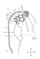
ドアトリム20は、図1及び図2に示すように、車内側を向く面を構成する主面部21と、主面部21の上部から車外側に向かって立ち上がるショルダー部23と、を有している。ショルダー部23は、座席に着座した乗員が肘を置いたり、車両用ドア10の開閉の際に手を掛けたりすることが想定されるため、外部から荷重が掛かり易い部分であるといえる。また、ドアトリム20には、ドアインサイドハンドルを取り付けるためのドアインサイドハンドル孔25や、アームレスト26、ドアポケット27等が設けられている。
As shown in FIGS. 1 and 2, the door trim 20 has a
ドアトリム20は、図1及び図2に示すように、トリムボード30を主体として構成されている。トリムボード30は、板状の基材31と、基材31の車外側板面31B(一方の板面)に設けられる樹脂成形体40と、を備えている。また、トリムボード30には、基材31の車内側板面31Aを覆うように表皮材28が貼着されている。
As shown in FIGS. 1 and 2, the door trim 20 is mainly composed of a
基材31は、繊維が熱可塑性樹脂により結着された構成を有している。基材31に用いられる繊維としては、例えばケナフ繊維が挙げられるが、繊維の種類はこれに限定されず、木質繊維、ガラス繊維や炭素繊維等を用いてもよい。また、本実施形態においては、熱可塑性樹脂の一例としてポリプロピレンを例示しているが、本発明の技術的範囲はこれに限定されない。
The
基材31は、図2に示すように、車両上方に向かうにつれて車外側に向けて湾曲する湾曲部33と、湾曲部33の上端から車外側に向けて延設された端末部34と、を有している。基材31は、略平板上のプレボードPを加熱プレスにより成形することで、湾曲部33、端末部34等の形状が付与されている。
As shown in FIG. 2, the
樹脂成形体40は、複数の第1リブ41及びランナー部45を有しており、それぞれが車外側板面31Bに立設されている。第1リブ41及びランナー部45はポリプロピレン等の熱可塑性樹脂により一体的に成形されている。また、第1リブ41が車外側板面31Bと接合されている側とは反対側の端部には第2リブ52が接合されており、第1リブ41と第2リブ52とで接合リブ51を形成している。なお、本実施形態においては、樹脂成形体40を構成する熱可塑性樹脂の一例として、ポリプロピレンを用いるものとする。
The resin molded
接合リブ51は、図1に示すように、車両前後方向に複数が並列するとともに車両前後方向と交差する方向に互いに並行して延びる構成とされる。本実施形態では、複数の接合リブ51が、基材31における湾曲部33と端末部34に跨るように、車両上下方向に互いに並行して延びる構成とされている。
As shown in FIG. 1, a plurality of joining
また、第1リブ41は、図3に示すように、その車外側の端部において車両上下方向に沿ってアンカー溝42が形成されている。アンカー溝42は、その口元よりも内部の方が幅広となっており、後述する第2リブ52が有するアンカー突起53と嵌合する形状とされる。
Further, as shown in FIG. 3, the
ランナー部45は、図2から図4に示すように、車外側板面31Bから車外側に向けて突出する突条状をなし、隣り合う第1リブ41同士の間を繋ぐように、車両前後方向に沿って一列に並んで複数形成されている。なお、ランナー部45は、トリムボード30を射出成形により成形する際に、複数の第1リブ41に対して溶融樹脂67を供給するための溶融樹脂67の流路(ランナー)に満たされていた樹脂が固化したものである。
As shown in FIGS. 2 to 4, the
第2リブ52は、第1リブ41に用いられている熱可塑性樹脂よりも剛性の高い高剛性材料からなり、全体としては車両上下方向に沿って延びる帯状をなしている。また、第2リブ52は、基材31側に向けて立設されるアンカー突起53を有している。そして、アンカー突起53は基端側(図3における車内側)よりも先端側(図3における車外側)の方が幅広である幅広突起部54を有している。第2リブ52のアンカー突起53は上述した第1リブ41のアンカー溝42と嵌合した状態で接合されており、接合リブ51を形成している。本実施形態においては、高剛性材料の一例としてABS樹脂(アクリロニトリルブタジエンスチレン)を例示するが、これに限定されず、第1リブ41に用いられる熱可塑性樹脂よりも高剛性であれば、樹脂、金属、天然素材等に関わらず高剛性材料として適用可能である。また、第2リブ52は、射出成形で一体的に成形される第1リブ41やランナー部45とは異なり、他の工程で別途作製されたものである。
The
次に、基材31の構成について説明する。基材31は、図3及び図4に示すように、樹脂成形体40(第1リブ41及びランナー部45)が接合される接合部35と、接合部35の周辺部分である周辺部36と、接合部35及び周辺部36以外の部分である一般部38と、を有している。接合部35及び周辺部36は、一般部38よりも厚みが小さい薄板部37とされる。なお、図3及び図4においては、薄板部37の領域には網掛けを付している。
Next, the structure of the
一般部38は、図3に示すように、基材31における薄板部37の周囲に位置する所定の板厚を有する板状の部分であり、基材31の大部分を占めている。一方、薄板部37は、接合部35に沿って延設された、一定幅を有する帯状の領域を交差させてできた領域に限り局在して形成されている。
As shown in FIG. 3, the
接合部35は、図3に示すように、樹脂成形体40と基材31が接合される部分である。詳細に述べると、接合部35においては、樹脂成形体40の成形時に樹脂成形体40の材料である溶融した熱可塑性樹脂が一部含浸してその後固化している。そして固化した樹脂のアンカー効果や溶着効果により、樹脂成形体40が接合部35に固着されるようになっている。
As shown in FIG. 3, the
薄板部37は、図3に示すように、一般部38よりも板厚方向に圧縮された部分とされ、一般部38に比して密度(単位体積当たりの繊維及び熱可塑性樹脂の重さ)が高くなっている。また、薄板部37は、所定の幅を有し、樹脂成形体40を取り囲むように形成されている。後に詳述するが、このような構成により、溶融樹脂67が接合部35の周囲に漏れ出る事態を抑制できるようになっている。
As shown in FIG. 3, the
本実施形態に係る薄板部37の板厚は、一般部38の板厚を基準としてその60%以下とされる。また、薄板部37の幅は、薄板部37の板厚以上とされる。本実施形態に係る薄板部37は、車外側板面31Bを凹ませるようにして形成されている。一方、基材31における車内側板面31Aは薄板部37のような凹凸を有さず平坦な面とされ、車内側板面31Aは表皮材28に被覆されてドアトリム20の意匠面を構成している。
The thickness of the
次に、ドアトリム20を製造する成形装置60について、図5から図7を参照しつつ説明する。成形装置60は、射出プレス成形装置とされ、一対の成形型61,62と、射出装置65とを備えている。本実施形態では、上側に配された成形型61が基材31の車内側板面31Aを成形するキャビ型とされ、下側に配された成形型62が基材31の車外側板面31Bを成形するコア型とされるものを例示する。射出装置65は、例えばスクリュータイプのものとされ、ノズル66からゲート64へと溶融樹脂67を圧送できるようになっている。射出装置65は、本実施形態では成形型62に設けられている。
Next, the
成形型61は、駆動装置(例えば、電動モータ、エアシリンダ、油圧シリンダ等)によって成形型62に対して移動可能であり、成形型61を成形型62に対して接近及び離隔させることで、型閉じ及び型開きができる構成となっている。図5に示す型開き状態では、成形型61,62の間にプレボードPが配される。
The
成形型62は、図6に示すように、型閉じ状態では成形型61に対して基材31の一般部38における板厚だけ離隔して対向配置される。これにより、成形型61と成形型62との間には基材31を成形するための基材成形空間70が形成される。成形型61,62でプレボードPをプレスすると、プレボードPが基材成形空間70の形状に対応する形に圧縮され、その結果、基材31が成形される。
As shown in FIG. 6, the
本実施形態に係るトリムボード30を成形する際の成形型62は、図5に示すように、成形面62Aにおいて、第1リブ41を成形するためのリブ成形空間71と、リブ成形空間71に連通して、各リブ成形空間71に溶融樹脂67を供給するための樹脂流動路であるランナー72(図5の断面では視認されないため破線で示している)が凹設されている。ランナー72は、ゲート64において射出装置65のノズル66と連結されている。このような構成により、ノズル66からゲート64へ射出された溶融樹脂67は、ランナー72を通じて流動し、複数のリブ成形空間71に到達するようになっている。
As shown in FIG. 5, the
また、成形型62の成形面62Aには、リブ成形空間71及びランナー72の周囲に、成形型61に向かって突出する突出部63が形成されている。この突出部63は、基材31における薄板部37を成形するためのものであり、突出端面の形状は、図3及び図4において網掛けを付して示す薄板部37の形状に対応している。
Furthermore, a
次に、成形装置60によるドアトリム20の製造方法について、図5から図7を参照しつつ説明する。本実施形態に係るドアトリム20の製造方法は、プレボードPを成形するプレボード成形工程と、成形型62の所定の位置に第2リブ52を配設する第2リブ配設工程と、成形型61,62によってプレボードPから基材31をプレス成形する基材成形工程と、成形型61,62によって基材31がプレスされた状態で、基材31に接合された樹脂成形体40を成形する成形体成形工程と、を備えている。
Next, a method for manufacturing the door trim 20 using the
プレボード成形工程では、繊維と糸状に加工された熱可塑性樹脂とが混紡されたマット材を加熱して、平板状に成形する。そして、成形された平板状の成形品を、所定のサイズに切断することによりプレボードPを得る。プレボードPの板厚及び密度は、板面方向において略均一なものとされている。 In the preboard molding process, a mat material made of a blend of fibers and a thermoplastic resin processed into threads is heated and molded into a flat plate. Then, the pre-board P is obtained by cutting the flat plate-shaped molded product into a predetermined size. The board thickness and density of the pre-board P are substantially uniform in the board surface direction.
次いで、第2リブ配設工程では、成形型62におけるリブ成形空間71の最奥部に第2リブ52を配設する。
Next, in the second rib arrangement step, the
次いで、基材成形工程では、プレボードPを再度ポリプロピレンが溶融軟化する程度に加熱し、成形型61,62の間にセット(図5参照)した後に型閉じする(図6参照)。これにより、成形型61,62によって、プレボードPから基材31がプレス成形される。
Next, in the base material forming step, the preboard P is heated again to such an extent that the polypropylene is melted and softened, and after being set between the
なお、基材成形工程では、薄板部37の板厚が一般部38の板厚より小さくなるようにプレス成形される。この際、プレボードPにおいて、成形型62における突出部63と対向する箇所(薄板部37に相当する箇所)には、突出部63以外の平坦な部分と対向する箇所(一般部38に相当する箇所)に比して高いプレス圧が掛かる。この結果、薄板部37が一般部38より高密度な状態に圧縮されるとともに、成形型62(突出部63)と薄板部37との間に隙間を生じ難くなる。
In the base material forming step, the
次いで、成形体成形工程では、成形型61,62を型閉じした状態のままで、射出装置65からゲート64に溶融樹脂67が射出される(図7参照)。溶融樹脂67は、ランナー72内を流動し、各リブ成形空間71へと到達する。本実施形態では、ランナー72は直線状に配されているため、溶融樹脂67は迂回することなく短時間でランナー72の端部まで到達して、各リブ成形空間71に充填される。
Next, in the molding step,
リブ成形空間71に充填された溶融樹脂67は、接合部35において基材31内部の軟化した熱可塑性樹脂を押し込みつつ、繊維の内部へと浸透する。繊維の内部に浸透した溶融樹脂67は、基材31内部の軟化した熱可塑性樹脂と一部混ざり合う。この際、基材31における接合部35の周囲に位置する薄板部37は一般部38に比べて高密度な状態となっているから、仮に当該部分が一般部38と同様の密度を有している構成と比べて、接合部35に浸透した溶融樹脂67が薄板部37側にまで拡がり難くなっている。さらに、薄板部37は、突出部63との間に隙間を生じ難い構成とされており、そのような隙間から溶融樹脂67が漏れ出し難くなっている。仮に溶融樹脂67が接合部35の周囲に漏れ出た場合には、漏れ出た分の樹脂が不足してリブ成形空間71を満たすことができなくなる。この場合は溶融樹脂67がリブ成形空間71の端部にまで到達せず欠肉が生じたり、溶融樹脂67の固化後にヒケが生じたりといった不具合が発生するおそれがある。しかし、薄板部37を形成することでこれを抑制できる。このようにして、基材31の一方の板面31Bに第1リブ41が形成される。
The
また、リブ成形空間71に充填された溶融樹脂67は、リブ成形空間71の最奥部にあらかじめ配されている第2リブ52とも接触する。そして、第2リブ52は上述したように基材側に向かって立設されたアンカー突起53を有している。アンカー突起53はその先端に幅広突起部54を有しており、溶融樹脂67はアンカー突起53の周囲を隙間なく満たす。これにより、第1リブ41と第2リブ52とが接合されて接合リブ51が形成される。
Furthermore, the
この後、成形型61,62を開き、脱型すると、基材31、樹脂成形体40、及び第2リブ52が一体となったトリムボード30が得られる。そして、トリムボード30に表皮材28を貼着する工程や、ドアインサイドハンドル等の各種機能部品を取り付ける工程等を経て、ドアトリム20が完成する。
Thereafter, the
続いて、本実施形態に係るトリムボード30の作用及び効果について説明する。本実施形態に係るトリムボード30は、熱可塑性樹脂を含む板状の基材31と、基材31の車外側板面31Bに立設される接合リブ51と、を備え、接合リブ51は、熱可塑性樹脂からなり、車外側板面31Bに接合される第1リブ41と、第1リブ41における一方の板面と反対側に接合される第2リブ52と、を有し、第2リブ52は、熱可塑性樹脂よりも剛性が高い高剛性材料からなることを特徴とする。
Next, the functions and effects of the
このような構成では、基材31に外力が作用しても、車外側板面31Bに立設された接合リブ51によって応力が分散され、成形構造体の変形が抑制される。そして、接合リブ51は、熱可塑性樹脂(ポリプロピレン)からなる第1リブ41と、熱可塑性樹脂よりも高剛性の高剛性材料(ABS樹脂)からなる第2リブ52とが接合されたものである。そのため、接合リブ51と同一形状、同一サイズであって熱可塑性樹脂のみからなるリブと比較すると、接合リブ51の方が剛性は高くなる。これにより、リブを大きくしたり、数を増やしたりせずとも剛性を高められるため、重量増を抑制しつつトリムボード30の変形を抑制できる。
In such a configuration, even if an external force acts on the
また、接合リブ51は、熱可塑性樹脂からなる第1リブ41の端部にさらに第2リブ52が接合された構成であるため、第2リブ52の高さを大きくすることで、容易に接合リブ51の高さを大きくすることができる。これにより、接合リブ51の剛性を高められ、トリムボード30の変形を抑制できる。
Furthermore, since the joining
以下、短冊状の基材82,84と1つのリブ(単独リブ83又は接合リブ85のいずれか)のみからなる単純化したモデルを実際に作製して行った剛性評価試験の測定結果を用いて、本発明の効果を説明する。なお、本発明の技術的範囲は本評価試験で用いた従来モデル80及び比較モデル81の構成によって何ら限定されるものではない。
Below, we will use the measurement results of a rigidity evaluation test conducted by actually fabricating a simplified model consisting of only strip-shaped
従来モデル80は、図8に示すように、板厚1.9mm、短手方向の幅が50mmであり、長手方向に十分な長さを有する短冊状の基材82上に、高さ8mm、幅3mmの単独リブ83が基材82の長手方向に沿って形成されたものである。基材82は繊維及び熱可塑性樹脂を含み、繊維としてケナフ繊維が、熱可塑性樹脂としてポリプロピレンが用いられている。また、単独リブ83は、全体がポリプロピレンにより形成されている。この従来モデル80は、従来の構成、つまり単一の材料のみからなるリブを想定したものである。
As shown in FIG. 8, the
一方、比較モデル81は、図9に示すように、上記基材82と同寸法かつ同材料である基材84上に、高さ8mm、幅3mmの接合リブ85が基材84の長手方向に沿って形成された構成である。接合リブ85のうち、基端から3mmまでの部分は第1リブ86とされ、基材84に用いられている熱可塑性樹脂と同じ熱可塑性樹脂(ポリプロピレン)により形成される。そして、その位置から先端までの5mm分は高剛性材料からなる第2リブ87とされる。剛性評価試験で用いた高剛性材料は、ABS樹脂(ABS)、ポリカーボネート(PC)、グラスファイバーを30%含有するポリカーボネート(PC(GF30%))、グラスファイバーを30%含有するポリアミド66(PA66(GF30%))、アクリル樹脂(PMMA)、フェノール樹脂(PF)、エポキシ樹脂(EP)、不飽和ポリエステル(UP)の8種類である。
On the other hand, in the
単独リブ83を有する従来モデル80、及び、接合リブ85を有する比較モデル81の剛性を評価するにあたり、3点曲げ試験を行った。その測定結果及び各材料の弾性率を図10の表に示す。
In evaluating the rigidity of the
従来モデル80の曲げ弾性勾配は、図10の表に示すように254[N/cm]であった。比較モデル81で得られた値がこの値を上回れば、接合リブ85によりリブ自体の剛性が高められ、その結果基材84の剛性も高められているといえる。図10の測定結果より、上述した8種の材料のうち、ポリカーボネート(PC)及びエポキシ樹脂(EP)を除く6種の高剛性材料の場合に、従来モデル80の値を上回ることを確認した。したがって、接合リブ85を有する比較モデル81において、第2リブ87の材料としてこれら6種の高剛性材料のいずれかを用いれば、リブ全体の形状、サイズが同じであっても、単独リブ83よりも剛性の高い接合リブ85を得ることができる。そして、このような接合リブ85の構成をトリムボード30の接合リブ51に適用することで、トリムボード30の変形を抑制することができる。
The bending elastic gradient of the
また、上記構成において、第1リブ41又は第2リブ52のいずれか一方は、他方と接する側に凹状のアンカー溝42を有し、第1リブ41又は第2リブ52のうちの他方は、一方と接する側に凸状のアンカー突起53を有し、第1リブ41と第2リブ52とはアンカー突起53とアンカー溝42が嵌合する形で接合されるものとすることができる。
Further, in the above configuration, either the
このような構成では、第1リブ41と第2リブ52とが互いに平面で接合している場合と比べて、アンカー溝42とアンカー突起53が有する凹凸の分、両者の接合面の面積が大きくなる。したがって、接合面におけるアンカー効果が増し、第1リブ41と第2リブ52とが強く接合して、両者は分離しにくくなる。その結果、接合リブ51の剛性を維持できるため、成形構造体の変形を抑制できる。
In such a configuration, compared to a case where the
また、上記構成において、アンカー突起53は、基端側よりも先端側の方が幅広である幅広突起部54を有し、アンカー溝42は、口元よりも内部の方が幅広の内部空間を有することを特徴とする請求項2に記載の成形構造体。
Furthermore, in the above configuration, the
このような構成によると、幅広突起部54を有するアンカー突起53は、アンカー溝42から抜けにくくなる。そのため、第1リブ41と第2リブ52をより強固に接合させることができる。これにより、第1リブ41から第2リブ52が分離してしまうことに起因する接合リブ51の剛性の低下を防ぎ、成形構造体の変形をさらに抑制できる。
With such a configuration, the
また、上記構成において、第1リブ41はアンカー溝42を有し、第2リブ52はアンカー突起53を有するものとすることができる。
Further, in the above configuration, the
ところで、第1リブ41と第2リブ52のように、異なる材料からなる部材を接合しつつ成形する方法として、インサート成形が知られている。具体的には、開いた金型内の所定の位置に、成形済みの第2リブ52をあらかじめ配しておき、その後金型を閉じて溶融樹脂67を射出する。このようにすると第1リブ41が成形されると同時に第1リブ41が第2リブ52と接合される。
By the way, insert molding is known as a method of molding members made of different materials, such as the
ここで仮に、第2リブ52が、口元よりも内部が幅広のアンカー溝42を有する場合には、アンカー溝42はアンダーカット形状となっている。この場合、第2リブ52の成形には複雑なスライド金型を要する。これに対し、第2リブ52がアンカー突起53を有する構成では、幅広部突起部の有無に関わらずスライド機構のない簡易な構成の金型で第2リブ52を成形することができる。
Here, if the
また、上記構成において、接合リブ51は車外側板面31Bに複数が並列に配されており、隣接する各第1リブ41は、熱可塑性樹脂からなるランナー部45により相互に接続されているものとすることができる。
Further, in the above configuration, a plurality of joining
このようにすれば、射出成形で複数の第1リブ41を成形するにあたり、溶融した熱可塑性樹脂を、ランナー部45を通じてスムーズに各第1リブ41まで到達させることができる。したがって、並列して配される複数の接合リブ51を容易に成形することができる。これにより、複数の接合リブ51により成形構造体の剛性が高められ、成形構造体の変形を抑制することができる。
In this way, when molding the plurality of
また、上記構成において、基材31は、熱可塑性樹脂により結着された繊維を含んでなり、第1リブ41及びランナー部45が接合される接合部35と、接合部35の周辺に配される周辺部36と、これら以外の部分である一般部38と、を有し、接合部35及び周辺部36は、一般部38よりも厚みが小さい薄板部37とされ、第2リブ52は、基材31上におけるランナー部45と第1リブ41とが交差する箇所の薄板部37に対し少なくとも重畳するように配されるものとすることができる。
Further, in the above configuration, the
トリムボード30に繊維を含む基材31を用いる場合には、接合部35及び周辺部36の厚みを小さくして繊維及び熱可塑性樹脂の密度を高めた薄板部37を形成することで、射出成形時における第1リブ41及びランナー部45の周辺への樹脂漏れが抑制される。これにより、溶融樹脂67の固化後にヒケが生じたり、樹脂がリブ成形空間71の隅々まで行き渡らずに欠肉が生じたりしてしまうことを抑制できる。
When the
しかし別の問題が発生してしまう。具体的には、第1リブ41及びランナー部45はドアトリム20(トリムボード30)におけるショルダー部23に配されており、前述したようにショルダー部23には外部から荷重が掛かることが多い。そして、特にランナー部45に沿って形成される薄板部37は、図4に示すように、車両前後方向に沿って連続的に配される。そのため、薄板部37が形成されることで、ショルダー部23に荷重が掛かる場合の、薄板部37を起点とする変形に対する剛性が不足するおそれがあった。
However, another problem arises. Specifically, the
そこで、このような構成とし、基材31上において少なくともランナー部45と第1リブ41とが交差する位置と重畳する位置には、第1リブ41だけでなく第2リブ52も配することとして、変形の起点となりうる位置における接合リブ51の剛性を高め、トリムボード30の変形を抑制することができる。
Therefore, with such a configuration, not only the
また、上記構成において、熱可塑性樹脂はポリプロピレンであり、前記高剛性材料はABS樹脂とすることができる。 Further, in the above configuration, the thermoplastic resin may be polypropylene, and the high-rigidity material may be ABS resin.
ポリプロピレンの弾性率は1100~1600MPa、ABS樹脂の弾性率は1900~2800MPaであり、後者の方が高剛性の材料である。したがって、第1リブ41にポリプロピレンを用い、第2リブ52にABS樹脂を用いることで、接合リブ51の剛性を高めて成形構造体の変形を抑制できる。
Polypropylene has an elastic modulus of 1100 to 1600 MPa, and ABS resin has an elastic modulus of 1900 to 2800 MPa, with the latter being a more rigid material. Therefore, by using polypropylene for the
また、ポリプロピレンの融点が約160°Cであるのに対し、ABS樹脂の融点は約110°Cと低い。そのため、このような構成では、第1リブ41と第2リブ52との界面において、加熱されて溶融したポリプロピレンと、これに接する第2リブ52の表面とが溶融し混ざり合い、その後固化することになる。すると、溶着効果によって第1リブ41と第2リブ52がより強固に接合され両者は分離しにくくなる。これにより、接合リブ51の剛性の低下を防ぎ、トリムボード30の変形を抑制できる。また、ポリプロピレン及びABS樹脂は、ともに車両の内装材によく用いられる材料であるため、容易に調達することができる。
Furthermore, while the melting point of polypropylene is about 160°C, the melting point of ABS resin is as low as about 110°C. Therefore, in such a configuration, at the interface between the
<他の実施形態>
本発明は上記記述及び図面によって説明した実施形態に限定されるものではなく、例えば次のような実施形態も本発明の技術的範囲に含まれ、さらに、下記以外にも要旨を逸脱しない範囲内で種々変更して実施することができる。
<Other embodiments>
The present invention is not limited to the embodiments described above and illustrated in the drawings; for example, the following embodiments are also included within the technical scope of the present invention; It can be implemented with various modifications.
(1)上述した実施形態では、第1リブ及び第2リブは、それぞれ1つずつのアンカー突起又はアンカー溝を有しているが、本発明の技術的範囲はこれに限定されず、各リブがそれぞれ複数のアンカー突起又はアンカー溝を有していてもよい。 (1) In the embodiment described above, each of the first rib and the second rib has one anchor protrusion or one anchor groove, but the technical scope of the present invention is not limited to this, and each rib has one anchor projection or one anchor groove. may each have a plurality of anchor projections or anchor grooves.
(2)上述した実施形態では、アンカー突起及びアンカー溝はともに接合リブの立設方向に沿って設けられているが、本発明の技術的範囲はこのような形態に限定されない。例えばアンカー突起及びアンカー溝が、接合リブの立設方向に対して斜めや垂直方向を向くように配設されていても構わない。 (2) In the embodiment described above, both the anchor protrusion and the anchor groove are provided along the direction in which the joining rib is erected, but the technical scope of the present invention is not limited to such a configuration. For example, the anchor protrusion and the anchor groove may be arranged so as to face diagonally or perpendicularly to the direction in which the joining rib is erected.
(3)上述した実施形態では、第1リブ又は第2リブのうち、いずれか一方の先端にアンカー突起が配されており、他方の先端にアンカー溝が配されているが、本発明の技術的範囲はこれに限定されない。例えばアンカー突起が一方の側面に配されていてもよく、アンカー溝が他方の側面に配されていても本発明の技術的範囲に含まれる。 (3) In the embodiment described above, the anchor protrusion is arranged at the tip of either the first rib or the second rib, and the anchor groove is arranged at the tip of the other rib, but the technology of the present invention The scope is not limited to this. For example, it is within the technical scope of the present invention that the anchor protrusion may be arranged on one side and the anchor groove may be arranged on the other side.
30…トリムボード(成形構造体)、31…基材、31A…車内側板面、31B…車外側板面(一方の板面)、33…湾曲部、34…端末部、35…接合部、36…周辺部、37…薄板部、38…一般部、40…樹脂成形体、41…第1リブ、42…アンカー溝、45…ランナー部、51…接合リブ、52…第2リブ、53…アンカー突起、54…幅広突起部 30... Trim board (molded structure), 31... Base material, 31A... Inner side plate surface, 31B... Outer side plate surface (one plate surface), 33... Curved part, 34... Terminal part, 35... Joint part, 36 ... Peripheral part, 37... Thin plate part, 38... General part, 40... Resin molded body, 41... First rib, 42... Anchor groove, 45... Runner part, 51... Joining rib, 52... Second rib, 53... Anchor Protrusion, 54... wide protrusion
Claims (7)
前記基材の一方の板面に立設される接合リブと、を備え、
前記接合リブは、
前記熱可塑性樹脂からなり、前記一方の板面に接合され、繊維を含まない第1リブと、
前記第1リブにおける前記一方の板面とは反対側に接合される第2リブと、を有し、
前記第2リブは、前記熱可塑性樹脂よりも剛性が高い高剛性材料からなり、
前記高剛性材料は、ABS樹脂、グラスファイバーを30%含有するポリカーボネート(PC(GF30%))、グラスファイバーを30%含有するポリアミド66(PA66(GF30%))、アクリル樹脂(PMMA)、フェノール樹脂(PF)、不飽和ポリエステル(UP)のいずれかである、成形構造体。 A plate-shaped base material containing thermoplastic resin and fibers,
a joining rib erected on one plate surface of the base material,
The joining rib is
a first rib made of the thermoplastic resin, joined to the one plate surface, and containing no fibers;
a second rib joined to the opposite side of the one plate surface of the first rib;
The second rib is made of a highly rigid material that is more rigid than the thermoplastic resin,
The high-rigidity materials include ABS resin, polycarbonate containing 30% glass fiber (PC (GF30%)), polyamide 66 (PA66 (GF30%)) containing 30% glass fiber, acrylic resin (PMMA), and phenolic resin. (PF), unsaturated polyester (UP).
前記第1リブ又は前記第2リブのうちの他方は、一方と接する側に凸状のアンカー突起を有し、
前記第1リブと前記第2リブとは、前記アンカー突起と前記アンカー溝が嵌合する形で接合されることを特徴とする請求項1に記載の成形構造体。 Either the first rib or the second rib has a concave anchor groove on the side in contact with the other rib,
The other one of the first rib and the second rib has a convex anchor protrusion on the side in contact with the other rib,
The molded structure according to claim 1, wherein the first rib and the second rib are joined in such a manner that the anchor protrusion and the anchor groove fit together.
前記アンカー溝は、口元よりも内部の方が幅広の内部空間を有することを特徴とする請求項2に記載の成形構造体。 The anchor protrusion has a wide protrusion that is wider on the distal side than on the proximal side,
The molded structure according to claim 2, wherein the anchor groove has an internal space that is wider inside than at the mouth.
隣接する各前記第1リブは、前記熱可塑性樹脂からなるランナー部により相互に接続されている請求項1から請求項4のいずれか1項に記載の成形構造体。 A plurality of the joining ribs are arranged in parallel on the one plate surface,
The molded structure according to any one of claims 1 to 4, wherein the adjacent first ribs are mutually connected by a runner portion made of the thermoplastic resin.
前記第1リブ及び前記ランナー部が接合される接合部と、
前記接合部の周辺に配される周辺部と、
これら以外の部分である一般部と、を有し、
前記接合部及び前記周辺部は、前記一般部よりも厚みが小さい薄板部とされ、
前記第2リブは、前記基材上における前記ランナー部と前記第1リブとが交差する箇所の前記薄板部に対し少なくとも重畳するように配される請求項5に記載の成形構造体。 The base material includes fibers bound by the thermoplastic resin,
a joint portion where the first rib and the runner portion are joined;
a peripheral portion disposed around the joint;
It has a general part which is a part other than these,
The joint portion and the peripheral portion are thin plate portions having a thickness smaller than the general portion,
The molded structure according to claim 5, wherein the second rib is disposed so as to at least overlap with the thin plate portion at a location on the base material where the runner portion and the first rib intersect.
Priority Applications (1)
| Application Number | Priority Date | Filing Date | Title |
|---|---|---|---|
| JP2020012286A JP7415599B2 (en) | 2020-01-29 | 2020-01-29 | molded structure |
Applications Claiming Priority (1)
| Application Number | Priority Date | Filing Date | Title |
|---|---|---|---|
| JP2020012286A JP7415599B2 (en) | 2020-01-29 | 2020-01-29 | molded structure |
Publications (2)
| Publication Number | Publication Date |
|---|---|
| JP2021115822A JP2021115822A (en) | 2021-08-10 |
| JP7415599B2 true JP7415599B2 (en) | 2024-01-17 |
Family
ID=77173685
Family Applications (1)
| Application Number | Title | Priority Date | Filing Date |
|---|---|---|---|
| JP2020012286A Active JP7415599B2 (en) | 2020-01-29 | 2020-01-29 | molded structure |
Country Status (1)
| Country | Link |
|---|---|
| JP (1) | JP7415599B2 (en) |
Citations (10)
| Publication number | Priority date | Publication date | Assignee | Title |
|---|---|---|---|---|
| JP2000142110A (en) | 1998-11-06 | 2000-05-23 | Takashimaya Nippatsu Kogyo Co Ltd | Door trim for automobile and manufacture of door trim |
| JP2000226021A (en) | 1999-02-03 | 2000-08-15 | Gifu Plast Ind Co Ltd | Carrying container and its manufacture |
| JP2008055848A (en) | 2006-09-01 | 2008-03-13 | Kasai Kogyo Co Ltd | Interior parts for automobiles and methods for producing the same |
| JP2011183585A (en) | 2010-03-05 | 2011-09-22 | Daiwa Kasei Kogyo Kk | Method of attaching separate member to molding or laminate, and molding or laminate attached with the member |
| JP2016196115A (en) | 2015-04-03 | 2016-11-24 | 豊田鉄工株式会社 | Hybrid molding method |
| JP2017080930A (en) | 2015-10-23 | 2017-05-18 | 三菱レイヨン株式会社 | Fiber-reinforced resin molded product and method for producing the same |
| JP2018176746A (en) | 2017-04-14 | 2018-11-15 | トヨタ紡織株式会社 | Resin molded body and method for producing the same |
| JP2018176576A (en) | 2017-04-14 | 2018-11-15 | トヨタ紡織株式会社 | Resin molded body and method for producing the same |
| JP2018202704A (en) | 2017-06-01 | 2018-12-27 | パナソニックIpマネジメント株式会社 | Method for producing resin molded article |
| JP2019089432A (en) | 2017-11-14 | 2019-06-13 | トヨタ紡織株式会社 | Vehicle door trim |
-
2020
- 2020-01-29 JP JP2020012286A patent/JP7415599B2/en active Active
Patent Citations (10)
| Publication number | Priority date | Publication date | Assignee | Title |
|---|---|---|---|---|
| JP2000142110A (en) | 1998-11-06 | 2000-05-23 | Takashimaya Nippatsu Kogyo Co Ltd | Door trim for automobile and manufacture of door trim |
| JP2000226021A (en) | 1999-02-03 | 2000-08-15 | Gifu Plast Ind Co Ltd | Carrying container and its manufacture |
| JP2008055848A (en) | 2006-09-01 | 2008-03-13 | Kasai Kogyo Co Ltd | Interior parts for automobiles and methods for producing the same |
| JP2011183585A (en) | 2010-03-05 | 2011-09-22 | Daiwa Kasei Kogyo Kk | Method of attaching separate member to molding or laminate, and molding or laminate attached with the member |
| JP2016196115A (en) | 2015-04-03 | 2016-11-24 | 豊田鉄工株式会社 | Hybrid molding method |
| JP2017080930A (en) | 2015-10-23 | 2017-05-18 | 三菱レイヨン株式会社 | Fiber-reinforced resin molded product and method for producing the same |
| JP2018176746A (en) | 2017-04-14 | 2018-11-15 | トヨタ紡織株式会社 | Resin molded body and method for producing the same |
| JP2018176576A (en) | 2017-04-14 | 2018-11-15 | トヨタ紡織株式会社 | Resin molded body and method for producing the same |
| JP2018202704A (en) | 2017-06-01 | 2018-12-27 | パナソニックIpマネジメント株式会社 | Method for producing resin molded article |
| JP2019089432A (en) | 2017-11-14 | 2019-06-13 | トヨタ紡織株式会社 | Vehicle door trim |
Also Published As
| Publication number | Publication date |
|---|---|
| JP2021115822A (en) | 2021-08-10 |
Similar Documents
| Publication | Publication Date | Title |
|---|---|---|
| US9364979B2 (en) | Molded structure body and method of producing the same | |
| US6620365B1 (en) | Method of manufacturing a convertible top assembly | |
| US20080295414A1 (en) | Automotive weather strip | |
| JP6107569B2 (en) | Manufacturing method of resin molding | |
| CN1927570B (en) | Method of manufacturing composite molded article and manufacturing apparatus of composite molded article | |
| JP5803572B2 (en) | Method for manufacturing molded structure | |
| JP2005239062A (en) | Structure of vehicle opening / closing body | |
| JP7415599B2 (en) | molded structure | |
| JP4572883B2 (en) | Interior panel and injection molding method | |
| JP5810840B2 (en) | Method for producing molded structure and mold | |
| JP6969306B2 (en) | Vehicle door trim | |
| JP5748105B2 (en) | Method for producing molded structure and mold | |
| JP7354880B2 (en) | Method of manufacturing molded structure | |
| JP2019142078A (en) | Manufacturing method of molded structure | |
| JP2022012776A (en) | Molding structure, and method for manufacturing molding structure | |
| JP2021142703A (en) | Molded structure | |
| JP5995095B2 (en) | Method for manufacturing molded structure | |
| KR20120137822A (en) | Crash pad panel for an automobile and manufacturing method thereof | |
| JP2596660B2 (en) | Joint structure of bumper reinforcement | |
| JP4001050B2 (en) | Manufacturing method of weather strip for automobile | |
| CN113508073A (en) | Composite structure and method for manufacturing same | |
| JP7352528B2 (en) | grass run | |
| JP2019171718A (en) | Manufacturing method of molded structure and mold | |
| JP3033410B2 (en) | Manufacturing method of long resin molded products | |
| JP3194572B2 (en) | Mold for forming laminate and method for forming laminate |
Legal Events
| Date | Code | Title | Description |
|---|---|---|---|
| A621 | Written request for application examination |
Free format text: JAPANESE INTERMEDIATE CODE: A621 Effective date: 20220823 |
|
| A977 | Report on retrieval |
Free format text: JAPANESE INTERMEDIATE CODE: A971007 Effective date: 20230613 |
|
| A131 | Notification of reasons for refusal |
Free format text: JAPANESE INTERMEDIATE CODE: A131 Effective date: 20230615 |
|
| A521 | Request for written amendment filed |
Free format text: JAPANESE INTERMEDIATE CODE: A523 Effective date: 20230808 |
|
| A131 | Notification of reasons for refusal |
Free format text: JAPANESE INTERMEDIATE CODE: A131 Effective date: 20230905 |
|
| A521 | Request for written amendment filed |
Free format text: JAPANESE INTERMEDIATE CODE: A523 Effective date: 20231019 |
|
| TRDD | Decision of grant or rejection written | ||
| A01 | Written decision to grant a patent or to grant a registration (utility model) |
Free format text: JAPANESE INTERMEDIATE CODE: A01 Effective date: 20231205 |
|
| A61 | First payment of annual fees (during grant procedure) |
Free format text: JAPANESE INTERMEDIATE CODE: A61 Effective date: 20231218 |
|
| R151 | Written notification of patent or utility model registration |
Ref document number: 7415599 Country of ref document: JP Free format text: JAPANESE INTERMEDIATE CODE: R151 |