JP7420932B2 - Tracking location using a scalable location tracking system - Google Patents
Tracking location using a scalable location tracking system Download PDFInfo
- Publication number
- JP7420932B2 JP7420932B2 JP2022523941A JP2022523941A JP7420932B2 JP 7420932 B2 JP7420932 B2 JP 7420932B2 JP 2022523941 A JP2022523941 A JP 2022523941A JP 2022523941 A JP2022523941 A JP 2022523941A JP 7420932 B2 JP7420932 B2 JP 7420932B2
- Authority
- JP
- Japan
- Prior art keywords
- camera
- time window
- coordinates
- frame
- determining
- Prior art date
- Legal status (The legal status is an assumption and is not a legal conclusion. Google has not performed a legal analysis and makes no representation as to the accuracy of the status listed.)
- Active
Links
Images




Classifications
-
- G—PHYSICS
- G06—COMPUTING OR CALCULATING; COUNTING
- G06V—IMAGE OR VIDEO RECOGNITION OR UNDERSTANDING
- G06V20/00—Scenes; Scene-specific elements
- G06V20/50—Context or environment of the image
- G06V20/52—Surveillance or monitoring of activities, e.g. for recognising suspicious objects
-
- G—PHYSICS
- G06—COMPUTING OR CALCULATING; COUNTING
- G06V—IMAGE OR VIDEO RECOGNITION OR UNDERSTANDING
- G06V40/00—Recognition of biometric, human-related or animal-related patterns in image or video data
- G06V40/10—Human or animal bodies, e.g. vehicle occupants or pedestrians; Body parts, e.g. hands
- G06V40/103—Static body considered as a whole, e.g. static pedestrian or occupant recognition
-
- G—PHYSICS
- G06—COMPUTING OR CALCULATING; COUNTING
- G06T—IMAGE DATA PROCESSING OR GENERATION, IN GENERAL
- G06T7/00—Image analysis
- G06T7/70—Determining position or orientation of objects or cameras
-
- G—PHYSICS
- G06—COMPUTING OR CALCULATING; COUNTING
- G06V—IMAGE OR VIDEO RECOGNITION OR UNDERSTANDING
- G06V10/00—Arrangements for image or video recognition or understanding
- G06V10/20—Image preprocessing
- G06V10/25—Determination of region of interest [ROI] or a volume of interest [VOI]
-
- G—PHYSICS
- G06—COMPUTING OR CALCULATING; COUNTING
- G06V—IMAGE OR VIDEO RECOGNITION OR UNDERSTANDING
- G06V10/00—Arrangements for image or video recognition or understanding
- G06V10/40—Extraction of image or video features
- G06V10/62—Extraction of image or video features relating to a temporal dimension, e.g. time-based feature extraction; Pattern tracking
Landscapes
- Engineering & Computer Science (AREA)
- Physics & Mathematics (AREA)
- General Physics & Mathematics (AREA)
- Theoretical Computer Science (AREA)
- Multimedia (AREA)
- Human Computer Interaction (AREA)
- Computer Vision & Pattern Recognition (AREA)
- Image Analysis (AREA)
- Closed-Circuit Television Systems (AREA)
Description
本開示は、一般に、人物および物体の物理的位置を追跡するための分散システムに関する。 TECHNICAL FIELD This disclosure generally relates to distributed systems for tracking physical locations of people and objects.
位置追跡システムは、人物および/または物体の物理的位置を追跡するために使用される。 Location tracking systems are used to track the physical location of people and/or objects.
位置追跡システムは、物理的空間(例えば、店舗)において人物および/または物体の物理的位置を追跡するために使用される。これらのシステムでは、典型的には、人物および/または物体の存在を検出するセンサ(例えば、カメラ)と、センサからの信号に基づいて人物および/または物体の物理的位置を決定するコンピュータとが使用される。店舗環境では、他のタイプのセンサを設置して、店舗内の在庫の動きを追跡することができる。例えば、重量センサをラックおよび棚に設置して、商品がいつこれらのラックおよび棚から取り出されたかを決定することができる。店舗内の人物の位置と、いつ商品が棚から取り出されたかの両方を追跡することによって、コンピュータは、店舗内のどのユーザが商品を取り出したかを決定し、レジで商品を打つ必要なしにそのユーザに商品の代金を請求することができる。換言すれば、人物は、店舗に歩いて入り、商品を取り、従来の精算プロセスのために立ち寄ることなく店から出ることができる。 Location tracking systems are used to track the physical location of people and/or objects in a physical space (eg, a store). These systems typically include a sensor (e.g., a camera) that detects the presence of a person and/or object and a computer that determines the physical location of the person and/or object based on signals from the sensor. used. In a store environment, other types of sensors can be installed to track the movement of inventory within the store. For example, weight sensors can be installed on racks and shelves to determine when items are removed from those racks and shelves. By tracking both the location of people in the store and when items are removed from the shelves, computers can determine which user in the store has removed an item and track that user without having to hit the item at the register. You can request payment for the product. In other words, a person can walk into a store, pick up an item, and leave the store without stopping for the traditional checkout process.
より大きな物理的空間(例えば、コンビニエンスストアおよび食料品店)の場合、追加のセンサを空間全体に設置して、人物および/または物体はその空間を動き回るときにそれらの位置を追跡することができる。例えば、追加のカメラを増設してより大きな空間内の位置を追跡したり、追加の重量センサを増設して追加の商品および棚を追跡したりすることができる。しかしながら、コンピュータの計算能力に達するまで追加することができるセンサの数には限りがある。結果として、コンピュータの計算能力は、追跡システムのカバレッジエリアを制限する。 For larger physical spaces (e.g., convenience stores and grocery stores), additional sensors can be installed throughout the space so that people and/or objects can track their location as they move around the space. . For example, additional cameras can be added to track locations within a larger space, and additional weight sensors can be added to track additional items and shelves. However, there is a limit to the number of sensors that can be added until the computing power of the computer is reached. As a result, the computing power of computers limits the coverage area of tracking systems.
より大きな空間を扱うようにこれらのシステムをスケーリングする1つの方法は、追加のコンピュータを増設し、これらのコンピュータ間でセンサを分割して、各コンピュータがセンサのサブセットからの信号を処理することができるようにする方法である。しかしながら、複数のコンピュータ間でセンサを分割すると、同期の問題が生じる。例えば、センサは、信号をそれぞれのコンピュータに一緒にまたは同時には通信しない可能性がある。別の例として、センサは、それぞれのコンピュータとの待ち時間が異なる場合があり、したがって、1つのセンサからの信号がコンピュータに到達するのに、別のセンサからの信号よりも長い時間がかかる場合がある。結果として、センサおよびコンピュータは互いに非同期化の状態になり、コンピュータが、空間における人物または物体の位置といつ商品が取り出されたかとを一貫して決定することがより困難になる。 One way to scale these systems to handle larger spaces is to add additional computers and divide the sensors between these computers so that each computer processes signals from a subset of the sensors. This is a way to make it possible. However, splitting the sensors between multiple computers creates synchronization problems. For example, the sensors may not communicate signals to their respective computers together or at the same time. As another example, sensors may have different latencies with their respective computers, so a signal from one sensor may take longer to reach the computer than a signal from another sensor. There is. As a result, the sensor and computer become unsynchronized with each other, making it more difficult for the computer to consistently determine the location of a person or object in space and when an item is removed.
本開示は、より大きな空間を扱うようにスケーリングすることができる従来にない分散型追跡システムを企図する。システムは、カメラのアレイ、複数のカメラクライアント、カメラサーバ、重量センサ、重量サーバ、および中央サーバを使用して、空間内のどの人物が商品を取り、その商品の代金を請求されるべきかを決定する。カメラクライアントはそれぞれ、カメラのアレイのカメラの異なるサブセットからのビデオのフレームを処理する。各カメラクライアントは、フレーム内で検出された人物の座標を決定し、次いで、フレームがいつカメラクライアントによって受信されたかに基づいて、これらの座標にタイムスタンプを付ける。次いで、カメラクライアントは、カメラクライアントからの情報を調整することを担うカメラサーバに座標およびタイムスタンプを通信する。カメラサーバは、カメラクライアントからの座標およびタイムスタンプに基づいて、空間内の人物の位置を決定する。重量サーバは、重量センサからの信号を処理して、商品がいつ空間内の棚から取り出されたかを決定する。中央サーバは、カメラサーバからの空間内の人物の位置と、商品がいつ棚から取り出されたかについての重量サーバからの決定とを使用して、空間内のどの人物がどの商品を取ったか、そしてその代金が請求されるべきかを決定する。 The present disclosure contemplates a non-traditional distributed tracking system that can be scaled to handle larger spaces. The system uses an array of cameras, multiple camera clients, a camera server, weight sensors, a weight server, and a central server to determine which person in the space should pick up an item and be charged for that item. decide. Each camera client processes frames of video from a different subset of cameras in the camera array. Each camera client determines the coordinates of the person detected within the frame and then timestamps these coordinates based on when the frame was received by the camera client. The camera client then communicates the coordinates and timestamp to the camera server, which is responsible for coordinating information from the camera client. The camera server determines the location of the person in space based on coordinates and timestamps from the camera client. The weight server processes signals from the weight sensors to determine when an item is removed from a shelf within the space. The central server uses the location of the person in the space from the camera server and the determination from the weight server about when the item was taken from the shelf to determine which person in the space took which item, and Determine if the money should be charged.
一般に、カメラサーバは、タイムスタンプに基づいて複数のカメラクライアントからの座標を時間窓に割り当てることによって、非同期化を防ぐ。次に、カメラサーバは、特定の時間窓に割り当てられた座標を処理して、その時間窓中の空間内の人物の全体的な座標を決定する。時間窓の持続時間は、非同期化の影響を軽減するために、発生すると予想される非同期化よりも長くなるように設定され得る。例えば、カメラおよびカメラクライアントが数ミリ秒だけ非同期化すると予想される場合、非同期化を打ち消すために時間窓を100ミリ秒持続するように設定することができる。このように、カメラおよびカメラクライアントの数を増加させて、任意の好適な空間を扱うようにシステムをスケーリングすることができる。 Generally, camera servers prevent desynchronization by assigning coordinates from multiple camera clients to time windows based on timestamps. The camera server then processes the coordinates assigned to a particular time window to determine the overall coordinates of the person in space during that time window. The duration of the time window may be set to be longer than the expected desynchronization to occur in order to reduce the effects of desynchronization. For example, if the camera and camera client are expected to desynchronize by a few milliseconds, a time window can be set to last 100 milliseconds to counteract the desynchronization. In this way, the system can be scaled to handle any suitable space by increasing the number of cameras and camera clients.
本開示はまた、カメラのアレイ内のカメラをカメラクライアントに配線する従来にない方法を企図する。カメラは、空間の上方に矩形グリッドとして配置される。グリッド内の各カメラは、特定の規則にしたがって特定のカメラクライアントに配線される。例えば、グリッドの同じ行または列において互いに直接隣接するカメラで同じカメラクライアントに配線されるものはない。別の例として、グリッド内で対角線に沿って配置されたカメラは、同じカメラクライアントに配線される。このように、グリッドの小さなエリアには、システム内の各カメラクライアントに配線されたカメラが含まれるべきである。結果として、1つのカメラクライアントがオフラインになったとしても(例えば、メンテナンス、エラー、またはクラッシュ)、残りのカメラクライアントから、この小さいエリア内の人物の位置を追跡するのに十分なカバレッジが依然として存在することになる。したがって、カメラのこの配置は、システムの回復力を高める。 The present disclosure also contemplates a non-conventional method of wiring cameras in an array of cameras to camera clients. Cameras are placed in a rectangular grid above the space. Each camera in the grid is wired to a specific camera client according to specific rules. For example, no cameras directly adjacent to each other in the same row or column of the grid are wired to the same camera client. As another example, cameras placed diagonally within the grid are wired to the same camera client. Thus, a small area of the grid should contain the cameras wired to each camera client in the system. As a result, even if one camera client goes offline (e.g. due to maintenance, error, or crash), there is still sufficient coverage from the remaining camera clients to track the location of a person within this small area. I will do it. This arrangement of cameras therefore increases the resilience of the system.
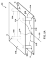
本開示はさらに、商品がいつラックおよび棚から取り出されたかを追跡するための重量センサを統合する、従来にないラックおよび棚の設計を企図する。一般に、ラックは、ベースと、垂直パネルと、棚とを含む。ベースは、プリント回路基板が配置された密閉空間を形成し、ベースは、密閉空間および回路基板へのアクセスを提供するために開く引き出しを含む。垂直パネルはベースに取り付けられ、棚は垂直パネルに取り付けられる。重量センサが棚内に配置される。ベース、パネル、および棚は、それぞれキャビティを画定する。棚のキャビティおよびパネルのキャビティは、少なくとも部分的に位置合わせされる。各重量センサは、その重量センサから、棚のキャビティ、パネルのキャビティ、およびベースのキャビティを通って回路基板まで延びるワイヤを介してプリント回路基板に信号を通信する。 The present disclosure further contemplates non-conventional rack and shelf designs that integrate weight sensors to track when items are removed from the racks and shelves. Generally, a rack includes a base, a vertical panel, and a shelf. The base defines an enclosed space in which a printed circuit board is disposed, and the base includes a drawer that opens to provide access to the enclosed space and the circuit board. Vertical panels are attached to the base and shelves are attached to the vertical panels. A weight sensor is placed within the shelf. The base, panel, and shelf each define a cavity. The shelf cavity and panel cavity are at least partially aligned. Each weight sensor communicates a signal from the weight sensor to the printed circuit board via wires that extend through the shelf cavity, the panel cavity, and the base cavity to the circuit board.
特定の実施形態は、空間内の人物および/または物体の位置を追跡するために異なる機能を実行する別個の構成要素(例えば、カメラクライアント、カメラサーバ、重量サーバ、および中央サーバ)を含む従来にない追跡システムを含む。システムの機能をこれらの様々な構成要素の間に広げることによって、システムは、より多くのセンサ(例えば、カメラおよび重量センサ)からの信号を処理することができる。センサの数の増加により、システムは、より大きな空間内の人物および/または物体を追跡することができる。結果として、システムは、(例えば、追加のカメラクライアントを増設することによって)より大きな空間を扱うようにスケーリングされ得る。追跡システムの特定の実施形態を以下に説明する。 Certain embodiments conventionally include separate components (e.g., a camera client, a camera server, a weight server, and a central server) that perform different functions to track the location of people and/or objects in a space. No tracking system included. By spreading the functionality of the system between these various components, the system can process signals from more sensors (eg, cameras and weight sensors). The increased number of sensors allows the system to track people and/or objects within a larger space. As a result, the system can be scaled to handle larger spaces (eg, by adding additional camera clients). Particular embodiments of tracking systems are described below.
一実施形態によれば、システムは、カメラのアレイと、第1のカメラクライアントと、第2のカメラクライアントと、カメラサーバと、複数の重量センサと、重量サーバと、中央サーバとを含む。カメラのアレイは、空間の上方に配置される。カメラのアレイの各カメラは、空間の一部のビデオをキャプチャする。空間の中には人物がいる。第1のカメラクライアントは、カメラのアレイの第1のカメラから第1のビデオの第1の複数のフレームを受信する。第1の複数のフレームの各フレームは、空間内の人物を示す。第1の複数のフレームのうちの第1のフレームについて、第1のカメラクライアントは、第1のフレームに示される人物の周りの第1の境界エリアを決定し、第1のフレームが第1のカメラクライアントによって受信されたときの第1のタイムスタンプを生成する。第1の複数のフレームのうちの第2のフレームについて、第1のカメラクライアントは、第2のフレームに示される人物の周りの第2の境界エリアを決定し、第2のフレームが第1のカメラクライアントによって受信されたときの第2のタイムスタンプを生成する。第2のカメラクライアントは、第1のカメラクライアントとは別個である。第2のカメラクライアントは、カメラのアレイの第2のカメラから第2のビデオの第2の複数のフレームを受信する。第2の複数のフレームの各フレームは、空間内の人物を示す。第2の複数のフレームのうちの第3のフレームについて、第2のカメラクライアントは、第3のフレームに示される人物の周りの第3の境界エリアを決定し、第3のフレームが第2のカメラクライアントによって受信されたときの第3のタイムスタンプを生成する。第2の複数のフレームのうちの第4のフレームについて、第2のカメラクライアントは、第4のフレームに示される人物の周りの第4の境界エリアを決定し、第4のフレームが第2のカメラクライアントによって受信されたときの第4のタイムスタンプを生成する。 According to one embodiment, a system includes an array of cameras, a first camera client, a second camera client, a camera server, a plurality of weight sensors, a weight server, and a central server. An array of cameras is placed above the space. Each camera in the array of cameras captures video of a portion of space. There are people in space. A first camera client receives a first plurality of frames of a first video from a first camera of the array of cameras. Each frame of the first plurality of frames depicts a person in space. For a first frame of the first plurality of frames, the first camera client determines a first bounding area around the person shown in the first frame, and the first frame Generate a first timestamp as received by the camera client. For a second frame of the first plurality of frames, the first camera client determines a second bounding area around the person shown in the second frame, such that the second frame Generate a second timestamp as received by the camera client. The second camera client is separate from the first camera client. A second camera client receives a second plurality of frames of a second video from a second camera of the array of cameras. Each frame of the second plurality of frames depicts a person in space. For a third frame of the second plurality of frames, the second camera client determines a third bounding area around the person shown in the third frame, and the third frame Generate a third timestamp as received by the camera client. For a fourth frame of the second plurality of frames, the second camera client determines a fourth bounding area around the person shown in the fourth frame, and the fourth frame Generate a fourth timestamp as received by the camera client.
カメラサーバは、第1および第2のカメラクライアントとは別個である。カメラサーバは、第1のタイムスタンプが第1の時間窓内に入ると決定し、第1のタイムスタンプが第1の時間窓内に入ると決定することに応答して、第1の境界エリアを画定する座標を第1の時間窓に割り当てる。カメラサーバはまた、第2のタイムスタンプが第1の時間窓内に入ると決定し、第2のタイムスタンプが第1の時間窓内に入ると決定することに応答して、第2の境界エリアを画定する座標を第1の時間窓に割り当てる。カメラサーバはさらに、第3のタイムスタンプが第1の時間窓内に入ると決定し、第3のタイムスタンプが第1の時間窓内に入ると決定することに応答して、第3の境界エリアを画定する座標を第1の時間窓に割り当てる。カメラサーバは、第4のタイムスタンプが第1の時間窓に続く第2の時間窓内に入ると決定し、第4のタイムスタンプが第2の時間窓内に入ると決定することに応答して、第4の境界エリアを画定する座標を第2の時間窓に割り当てる。 The camera server is separate from the first and second camera clients. The camera server determines that the first timestamp falls within the first time window, and in response to determining that the first timestamp falls within the first time window, a first bounding area. Assign coordinates defining the first time window. The camera server also determines that the second timestamp falls within the first time window, and in response to determining that the second timestamp falls within the first time window, a second boundary. Coordinates defining the area are assigned to the first time window. The camera server further determines that the third timestamp falls within the first time window and, in response to determining that the third timestamp falls within the first time window, determines a third boundary. Coordinates defining the area are assigned to the first time window. The camera server is responsive to determining that the fourth timestamp falls within a second time window subsequent to the first time window, and is responsive to determining that the fourth timestamp falls within the second time window. and assigning coordinates defining a fourth boundary area to the second time window.
カメラサーバはまた、第1の時間窓に割り当てられた座標が処理されるべきであると決定し、第1の時間窓に割り当てられた座標が処理されるべきであると決定することに応答して、カメラサーバは、第1の境界エリアを画定する座標と第2の境界エリアを画定する座標とに少なくとも基づいて、第1のカメラからの第1のビデオに対する第1の時間窓中の人物の結合座標(combined coordinate)を計算し、第3の境界エリアを画定する座標に少なくとも基づいて、第2のカメラからの第2のビデオに対する第1の時間窓中の人物の結合座標を計算する。カメラサーバはまた、第1のカメラからの第1のビデオに対する第1の時間窓中の人物の結合座標と、第2のカメラからの第2のビデオに対する第1の時間窓中の人物の結合座標とに少なくとも基づいて、第1の時間窓中の空間内の人物の位置を決定する。 The camera server is also responsive to determining that the coordinates assigned to the first time window should be processed and determining that the coordinates assigned to the first time window are to be processed. and the camera server determines the person during the first time window for the first video from the first camera based at least on the coordinates defining the first bounded area and the coordinates defining the second bounded area. and calculating the combined coordinates of the person in the first time window with respect to the second video from the second camera based at least on the coordinates defining a third bounding area. . The camera server also determines the binding coordinates of the person during the first time window to the first video from the first camera and the binding coordinates of the person during the first time window to the second video from the second camera. determining the position of the person in space during the first time window based at least on the coordinates of the person;
複数の重量センサは空間内に配置される。複数の重量センサの各重量センサは、その重量センサが経験する重量を示す信号を生成する。重量サーバは、第1および第2のカメラクライアントならびにカメラサーバとは別個である。重量サーバは、複数の重量センサのうちの第1の重量センサによって生成された信号に少なくとも基づいて、第1の重量センサの上方に配置された商品が取り出されたと決定する。中央サーバは、第1および第2のカメラクライアント、カメラサーバ、ならびに重量サーバとは別個である。中央サーバは、第1の時間窓中の空間内の人物の位置に少なくとも基づいて、人物が商品を取り出したと決定する。第1の人物が商品を取り出したという決定に少なくとも基づいて、その人物は、その人物が空間を出るときに商品の代金を請求される。 A plurality of weight sensors are arranged within the space. Each weight sensor of the plurality of weight sensors generates a signal indicative of the weight experienced by that weight sensor. The weight server is separate from the first and second camera clients and the camera server. The weight server determines that an item positioned above the first weight sensor has been removed based at least on a signal generated by a first weight sensor of the plurality of weight sensors. The central server is separate from the first and second camera clients, camera server, and weight server. The central server determines that the person has retrieved the item based at least on the position of the person in the space during the first time window. Based at least on the determination that the first person retrieved the item, that person is charged for the item when the person exits the space.
別の実施形態によれば、システムは、カメラのアレイと、第1のカメラクライアントと、第2のカメラクライアントと、カメラサーバと、複数の重量センサと、重量サーバと、中央サーバとを含む。カメラのアレイは、空間の上方に配置される。カメラのアレイの各カメラは、空間の一部のビデオをキャプチャする。空間の中には人物がいる。第1のカメラクライアントは、カメラのアレイの第1のカメラから受信される第1のビデオの各フレームについて、第1のビデオのそのフレームに示される人物の周りの境界エリアを決定し、第1のビデオのそのフレームが第1のカメラクライアントによって受信されたときのタイムスタンプを生成する。第2のカメラクライアントは、カメラのアレイの第2のカメラから受信される第2のビデオの各フレームについて、第2のビデオのそのフレームに示される人物の周りの境界エリアを決定し、第2のビデオのそのフレームが第2のカメラクライアントによって受信されたときのタイムスタンプを生成する。 According to another embodiment, a system includes an array of cameras, a first camera client, a second camera client, a camera server, a plurality of weight sensors, a weight server, and a central server. An array of cameras is placed above the space. Each camera in the array of cameras captures video of a portion of space. There are people in space. The first camera client determines, for each frame of the first video received from the first camera of the array of cameras, a bounding area around the person shown in that frame of the first video; generate a timestamp when that frame of the video was received by the first camera client. The second camera client determines, for each frame of the second video received from a second camera of the array of cameras, a bounding area around the person shown in that frame of the second video; generate a timestamp when that frame of the video was received by the second camera client.
カメラサーバは、第1および第2のカメラクライアントとは別個である。カメラサーバは、第1のビデオの各フレームについて、そのフレームが第1のカメラクライアントによって受信されたときのタイムスタンプに少なくとも基づいて、そのフレームに示される人物の周りの境界エリアを画定する座標を複数の時間窓のうちの1つに割り当てる。第2の複数のフレームの各フレームについて、カメラサーバは、そのフレームが第2のカメラクライアントによって受信されたときのタイムスタンプに少なくとも基づいて、そのフレームに示される人物の周りの境界エリアを画定する座標を複数の時間窓のうちの1つに割り当てる。複数の時間窓のうちの第1の時間窓について、カメラサーバは、(1)第1の複数のフレームに示される人物の周りの境界エリアを画定し、(2)第1の時間窓に割り当てられる座標に少なくとも基づいて、第1のカメラからの第1のビデオに対する第1の時間窓中の人物の結合座標を計算し、(1)第2の複数のフレームに示される人物の周りの境界エリアを画定し、(2)第1の時間窓に割り当てられる座標に少なくとも基づいて、第2のカメラからの第2のビデオに対する第1の時間窓中の人物の結合座標を計算する。カメラサーバは、第1のカメラからの第1のビデオに対する第1の時間窓中の人物の結合座標と、第2のカメラからの第2のビデオに対する第1の時間窓中の人物の結合座標とに少なくとも基づいて、第1の時間窓中の空間内の人物の位置を決定する。 The camera server is separate from the first and second camera clients. The camera server determines, for each frame of the first video, coordinates that define a bounded area around the person shown in the frame based at least on a timestamp when the frame was received by the first camera client. to one of a plurality of time windows. For each frame of the second plurality of frames, the camera server defines a bounded area around the person shown in the frame based at least on a timestamp when the frame was received by the second camera client. Assign coordinates to one of a plurality of time windows. For a first time window of the plurality of time windows, the camera server (1) defines a bounded area around the person shown in the first plurality of frames; compute joint coordinates of the person during a first time window with respect to a first video from a first camera based at least on the coordinates shown in the second plurality of frames; defining an area; and (2) calculating joint coordinates of the person in the first time window for a second video from a second camera based at least on the coordinates assigned to the first time window. The camera server determines the joint coordinates of the person during a first time window for a first video from a first camera and the joint coordinates of a person during a first time window for a second video from a second camera. determining the position of the person in space during the first time window based at least on the first time window;
複数の重量センサは空間内に配置される。重量サーバは、第1および第2のカメラクライアントならびにカメラサーバとは別個である。重量サーバは、複数の重量センサのうちの第1の重量センサによって生成された信号に少なくとも基づいて、第1の重量センサの上方に配置された商品が取り出されたと決定する。中央サーバは、第1および第2のカメラクライアント、カメラサーバ、ならびに重量サーバとは別個である。中央サーバは、第1の時間窓中の空間内の人物の位置に少なくとも基づいて、人物が商品を取り出したと決定する。 A plurality of weight sensors are arranged within the space. The weight server is separate from the first and second camera clients and the camera server. The weight server determines that an item positioned above the first weight sensor has been removed based at least on a signal generated by a first weight sensor of the plurality of weight sensors. The central server is separate from the first and second camera clients, camera server, and weight server. The central server determines that the person has retrieved the item based at least on the position of the person in the space during the first time window.
追跡システムの特定の実施形態は、システムの構成要素(例えば、カメラクライアントおよびカメラサーバ)の間で多少の非同期化を許容にする従来にない追跡プロセスを実行する。一般に、システムは、時間窓にしたがって情報を処理する。これらの時間窓は、システムに存在すると予想される非同期化よりも長くなるように設定され得る。時間窓に割り当てられた情報は一緒に処理される。したがって、その情報の間に多少の非同期化が存在していても、同じ時間窓内で一緒に処理される。このように、追跡システムは、非同期化の量の増加、特に、システムがより大きな空間を扱うことができるようにシステムがより多くの構成要素を含むようにスケーリングされた結果として生じる非同期化を扱うことができる。結果として、システムは、信頼性および精度を維持しながら、より大きな空間を扱うようにスケーリングすることができる。追跡プロセスの特定の実施形態を以下に説明する。 Certain embodiments of the tracking system perform a non-traditional tracking process that allows for some degree of desynchronization between the components of the system (eg, camera client and camera server). Generally, systems process information according to time windows. These time windows may be set to be longer than the expected desynchronization that exists in the system. Information assigned to time windows is processed together. Therefore, even though there may be some desynchronization between the information, they are processed together within the same time window. In this way, the tracking system handles increasing amounts of desynchronization, especially desynchronization that results from scaling the system to include more components so that the system can handle larger spaces. be able to. As a result, the system can be scaled to handle larger spaces while maintaining reliability and accuracy. A specific embodiment of the tracking process is described below.
一実施形態によれば、システムは、カメラのアレイと、第1のカメラクライアントと、第2のカメラクライアントと、カメラサーバとを含む。カメラのアレイは、空間の上方に配置される。カメラのアレイの各カメラは、空間の一部のビデオをキャプチャする。空間の中には人物がいる。第1のカメラクライアントは、カメラのアレイの第1のカメラから第1のビデオの第1の複数のフレームを受信する。第1の複数のフレームの各フレームは、空間内の人物を示す。第1の複数のフレームのうちの第1のフレームについて、第1のカメラクライアントは、第1のフレームに示される人物の周りの第1の境界エリアを決定し、第1のフレームが第1のカメラクライアントによって受信されたときの第1のタイムスタンプを生成する。第1の複数のフレームのうちの第2のフレームについて、第1のカメラクライアントは、第2のフレームに示される人物の周りの第2の境界エリアを決定し、第2のフレームが第1のカメラクライアントによって受信されたときの第2のタイムスタンプを生成する。第1の複数のフレームのうちの第3のフレームについて、第1のカメラクライアントは、第3のフレームに示される人物の周りの第3の境界エリアを決定し、第3のフレームが第1のカメラクライアントによって受信されたときの第3のタイムスタンプを生成する。 According to one embodiment, a system includes an array of cameras, a first camera client, a second camera client, and a camera server. An array of cameras is placed above the space. Each camera in the array of cameras captures video of a portion of space. There are people in space. A first camera client receives a first plurality of frames of a first video from a first camera of the array of cameras. Each frame of the first plurality of frames depicts a person in space. For a first frame of the first plurality of frames, the first camera client determines a first bounding area around the person shown in the first frame, and the first frame Generate a first timestamp as received by the camera client. For a second frame of the first plurality of frames, the first camera client determines a second bounding area around the person shown in the second frame, such that the second frame Generate a second timestamp as received by the camera client. For a third frame of the first plurality of frames, the first camera client determines a third bounding area around the person shown in the third frame, and the third frame Generate a third timestamp as received by the camera client.
第2のカメラクライアントは、カメラのアレイの第2のカメラから第2のビデオの第2の複数のフレームを受信する。第2の複数のフレームの各フレームは、空間内の人物を示す。第2の複数のフレームのうちの第4のフレームについて、第2のカメラクライアントは、第4のフレームに示される人物の周りの第4の境界エリアを決定し、第4のフレームが第2のカメラクライアントによって受信されたときの第4のタイムスタンプを生成する。第2の複数のフレームのうちの第5のフレームについて、第2のカメラクライアントは、第5のフレームに示される人物の周りの第5の境界エリアを決定し、第5のフレームが第2のカメラクライアントによって受信されたときの第5のタイムスタンプを生成する。 A second camera client receives a second plurality of frames of a second video from a second camera of the array of cameras. Each frame of the second plurality of frames depicts a person in space. For a fourth frame of the second plurality of frames, the second camera client determines a fourth bounding area around the person shown in the fourth frame, and the fourth frame Generate a fourth timestamp as received by the camera client. For a fifth frame of the second plurality of frames, the second camera client determines a fifth bounding area around the person shown in the fifth frame, and the fifth frame Generate a fifth timestamp as received by the camera client.
カメラサーバは、第1および第2のカメラクライアントとは別個である。カメラサーバは、第1のタイムスタンプが第1の時間窓内に入ると決定し、第1のタイムスタンプが第1の時間窓内に入ると決定することに応答して、第1の境界エリアを画定する座標を第1の時間窓に割り当てる。カメラサーバはまた、第2のタイムスタンプが第1の時間窓内に入ると決定し、第2のタイムスタンプが第1の時間窓内に入ると決定することに応答して、第2の境界エリアを画定する座標を第1の時間窓に割り当てる。カメラサーバはさらに、第3のタイムスタンプが第1の時間窓に続く第2の時間窓内に入ると決定し、第3のタイムスタンプが第2の時間窓内に入ると決定することに応答して、第3の境界エリアを画定する座標を第2の時間窓に割り当てる。カメラサーバはまた、第4のタイムスタンプが第1の時間窓内に入ると決定し、第4のタイムスタンプが第1の時間窓内に入ると決定することに応答して、第4の境界エリアを画定する座標を第1の時間窓に割り当てる。カメラサーバはさらに、第5のタイムスタンプが第2の時間窓内に入ると決定し、第5のタイムスタンプが第2の時間窓内に入ると決定することに応答して、第5の境界エリアを画定する座標を第2の時間窓に割り当てる。 The camera server is separate from the first and second camera clients. The camera server determines that the first timestamp falls within the first time window, and in response to determining that the first timestamp falls within the first time window, a first bounding area. Assign coordinates defining the first time window. The camera server also determines that the second timestamp falls within the first time window, and in response to determining that the second timestamp falls within the first time window, a second boundary. Coordinates defining the area are assigned to the first time window. The camera server is further responsive to determining that the third timestamp falls within a second time window subsequent to the first time window, and is responsive to determining that the third timestamp falls within the second time window. and assigning coordinates defining a third bounded area to the second time window. The camera server also determines that the fourth timestamp falls within the first time window and, in response to determining that the fourth timestamp falls within the first time window, determines the fourth boundary. Coordinates defining the area are assigned to the first time window. The camera server further determines that the fifth timestamp falls within the second time window, and in response to determining that the fifth timestamp falls within the second time window, a fifth boundary. Coordinates defining the area are assigned to the second time window.
カメラサーバはまた、第1の時間窓に割り当てられた座標が処理されるべきであると決定し、第1の時間窓に割り当てられた座標が処理されるべきであると決定することに応答して、カメラサーバは、第1の境界エリアを画定する座標と第2の境界エリアを画定する座標とに少なくとも基づいて、第1のカメラからの第1のビデオに対する第1の時間窓中の人物の結合座標を計算し、第4の境界エリアを画定する座標に少なくとも基づいて、第2のカメラからの第2のビデオに対する第1の時間窓中の人物の結合座標を計算する。第1の時間窓に割り当てられた座標が処理されるべきであると決定した後、カメラサーバは、第2の時間窓に割り当てられた座標が処理されるべきであると決定し、第2の時間窓に割り当てられた座標が処理されるべきであると決定したことに応答して、カメラサーバは、第3の境界エリアを画定する座標に少なくとも基づいて、第1のカメラからの第1のビデオに対する第2の時間窓中の人物の結合座標を計算し、第5の境界エリアを画定する座標に少なくとも基づいて、第2のカメラからの第2のビデオに対する第2の時間窓中の人物の結合座標を計算する。 The camera server is also responsive to determining that the coordinates assigned to the first time window should be processed and determining that the coordinates assigned to the first time window are to be processed. and the camera server determines the person during the first time window for the first video from the first camera based at least on the coordinates defining the first bounded area and the coordinates defining the second bounded area. and calculating the joint coordinates of the person during the first time window with respect to the second video from the second camera based at least on the coordinates defining the fourth bounded area. After determining that the coordinates assigned to the first time window should be processed, the camera server determines that the coordinates assigned to the second time window should be processed, and the camera server determines that the coordinates assigned to the second time window should be processed and In response to determining that the coordinates assigned to the time window should be processed, the camera server detects the first coordinates from the first camera based at least on the coordinates defining the third bounded area. calculating the joint coordinates of the person in the second time window with respect to the video, the person in the second time window with respect to the second video from the second camera, based at least on the coordinates defining a fifth bounding area; Compute the bond coordinates of .
別の実施形態によれば、システムは、カメラのアレイと、第1のカメラクライアントと、第2のカメラクライアントと、カメラサーバとを含む。カメラのアレイは、空間の上方に配置される。カメラのアレイの各カメラは、空間の一部のビデオをキャプチャする。空間の中には人物がいる。第1のカメラクライアントは、カメラのアレイの第1のカメラから第1のビデオの第1の複数のフレームを受信する。第1の複数のフレームの各フレームは、空間内の人物を示す。第1の複数のフレームの各フレームについて、第1のカメラクライアントは、そのフレームに示される人物の周りの境界エリアを決定し、そのフレームが第1のカメラクライアントによって受信されたときのタイムスタンプを生成する。第2のカメラクライアントは、カメラのアレイの第2のカメラから第2のビデオの第2の複数のフレームを受信する。第2の複数のフレームの各フレームは、空間内の人物を示す。第2の複数のフレームの各フレームについて、第2のカメラクライアントは、そのフレームに示される人物の周りの境界エリアを決定し、そのフレームが第2のカメラクライアントによって受信されたときのタイムスタンプを生成する。 According to another embodiment, a system includes an array of cameras, a first camera client, a second camera client, and a camera server. An array of cameras is placed above the space. Each camera in the array of cameras captures video of a portion of space. There are people in space. A first camera client receives a first plurality of frames of a first video from a first camera of the array of cameras. Each frame of the first plurality of frames depicts a person in space. For each frame of the first plurality of frames, the first camera client determines a bounding area around the person shown in that frame and a timestamp of when the frame was received by the first camera client. generate. A second camera client receives a second plurality of frames of a second video from a second camera of the array of cameras. Each frame of the second plurality of frames depicts a person in space. For each frame of the second plurality of frames, the second camera client determines the bounding area around the person shown in that frame and timestamps when the frame was received by the second camera client. generate.
カメラサーバは、第1および第2のカメラクライアントとは別個である。カメラサーバは、第1の複数のフレームの各フレームについて、そのフレームが第1のカメラクライアントによって受信されたときのタイムスタンプに少なくとも基づいて、そのフレームに示される人物の周りの境界エリアを画定する座標を複数の時間窓のうちの1つに割り当て、第2の複数のフレームの各フレームについて、そのフレームが第2のカメラクライアントによって受信されたときのタイムスタンプに少なくとも基づいて、そのフレームに示される人物の周りの境界エリアを画定する座標を複数の時間窓のうちの1つに割り当てる。 The camera server is separate from the first and second camera clients. The camera server defines, for each frame of the first plurality of frames, a bounded area around the person shown in the frame based at least on a timestamp when the frame was received by the first camera client. assigning the coordinates to one of the plurality of time windows and, for each frame of the second plurality of frames, assigning the coordinates indicated to the frame based at least on a timestamp when the frame was received by the second camera client; Coordinates defining a bounded area around a person to be viewed are assigned to one of a plurality of time windows.
カメラサーバはまた、複数の時間窓のうちの第1の時間窓に割り当てられた座標が処理されるべきであると決定し、第1の時間窓に割り当てられた座標が処理されるべきであると決定することに応答して、(1)第1の複数のフレームに示される人物の周りの境界エリアを画定し、(2)第1の時間窓に割り当てられる座標に少なくとも基づいて、第1のカメラからの第1のビデオに対する第1の時間窓中の人物の結合座標を計算し、(1)第2の複数のフレームに示される人物の周りの境界エリアを画定し、(2)第1の時間窓に割り当てられる座標に少なくとも基づいて、第2のカメラからの第2のビデオに対する第1の時間窓中の人物の結合座標を計算する。 The camera server also determines that the coordinates assigned to the first time window of the plurality of time windows should be processed, and the coordinates assigned to the first time window are to be processed. (1) defining a bounded area around the person shown in the first plurality of frames; compute the joint coordinates of the person during a first time window with respect to the first video from the camera, (1) define a bounding area around the person shown in the second plurality of frames, and (2) Computing joint coordinates of the person in the first time window for the second video from the second camera based at least on the coordinates assigned to the first time window.
特定の実施形態は、カメラシステムの回復力を高めるカメラおよびカメラクライアントの従来にない配置を含む。一般に、カメラは、物理的空間にカバレッジを提供する矩形グリッド状に配置され、各カメラは、1つのカメラクライアントに通信可能に結合される。グリッドの同じ行または列において、同じカメラクライアントに通信可能に結合された別のカメラに直接隣接するカメラはない。グリッドの対角線に沿って配置されたカメラは、同じカメラクライアントに通信可能に結合される。このように、システム内の1つのカメラクライアントがオフラインになったとしても、グリッドは依然として物理的空間に十分なカバレッジを提供する。結果として、カメラのこの配置は、システムの回復力を高める。カメラ配置の特定の実施形態を以下に説明する。 Certain embodiments include unconventional placement of cameras and camera clients that increase the resiliency of the camera system. Generally, cameras are arranged in a rectangular grid that provides coverage in a physical space, and each camera is communicatively coupled to one camera client. No camera is directly adjacent to another camera communicatively coupled to the same camera client in the same row or column of the grid. Cameras located along the diagonal of the grid are communicatively coupled to the same camera client. In this way, even if one camera client in the system goes offline, the grid still provides sufficient coverage of the physical space. As a result, this arrangement of cameras increases the resilience of the system. Particular embodiments of camera placement are described below.
一実施形態によれば、システムは、第1のカメラクライアントと、第2のカメラクライアントと、第3のカメラクライアントと、カメラのアレイとを含む。第2のカメラクライアントは、第1のカメラクライアントとは別個である。第3のカメラクライアントは、第1および第2のカメラクライアントとは別個である。カメラのアレイは、空間の上方に配置される。カメラのアレイ内のカメラは、第1の行、第2の行、第3の行、第1の列、第2の列、および第3の列を含む矩形グリッドとして配置される。アレイは、第1、第2、第3、第4、第5、および第6のカメラを含む。 According to one embodiment, a system includes a first camera client, a second camera client, a third camera client, and an array of cameras. The second camera client is separate from the first camera client. The third camera client is separate from the first and second camera clients. An array of cameras is placed above the space. The cameras in the array of cameras are arranged as a rectangular grid including a first row, a second row, a third row, a first column, a second column, and a third column. The array includes first, second, third, fourth, fifth, and sixth cameras.
第1のカメラは、グリッドの第1の行および第1の列に配置される。第1のカメラは、第1のカメラクライアントに通信可能に結合される。第1のカメラは、空間の第1の部分のビデオを第1のカメラクライアントに通信する。第2のカメラは、第2のカメラがグリッド内で第1のカメラに直接隣接するようにグリッドの第1の行および第2の列に配置される。第2のカメラは、第2のカメラクライアントに通信可能に結合される。第2のカメラは、空間の第2の部分のビデオを第2のカメラクライアントに通信する。第3のカメラは、第3のカメラがグリッド内で第2のカメラに直接隣接するようにグリッドの第1の行および第3の列に配置される。第3のカメラは、第3のカメラクライアントに通信可能に結合される。第3のカメラは、空間の第3の部分のビデオを第3のカメラクライアントに通信する。第4のカメラは、第4のカメラがグリッド内で第1のカメラに直接隣接するようにグリッドの第2の行および第1の列に配置される。第4のカメラは、第2のカメラクライアントに通信可能に結合される。第4のカメラは、空間の第4の部分のビデオを第2のカメラクライアントに通信する。第5のカメラは、第5のカメラがグリッド内で第4のカメラおよび第2のカメラに直接隣接するようにグリッドの第2の行および第2の列に配置される。第5のカメラは、第3のカメラクライアントに通信可能に結合される。第5のカメラは、空間の第5の部分のビデオを第3のカメラクライアントに通信する。第6のカメラは、第6のカメラがグリッド内で第4のカメラに直接隣接するようにグリッドの第3の行および第1の列に配置される。第6のカメラは、第3のカメラクライアントに通信可能に結合される。第6のカメラは、空間の第6の部分のビデオを第3のカメラクライアントに通信する。 A first camera is placed in the first row and first column of the grid. A first camera is communicatively coupled to a first camera client. The first camera communicates video of the first portion of the space to the first camera client. The second camera is positioned in the first row and second column of the grid such that the second camera is directly adjacent to the first camera within the grid. A second camera is communicatively coupled to a second camera client. A second camera communicates video of a second portion of the space to a second camera client. A third camera is positioned in the first row and third column of the grid such that the third camera is directly adjacent to the second camera in the grid. A third camera is communicatively coupled to a third camera client. A third camera communicates video of a third portion of the space to a third camera client. A fourth camera is placed in the second row and first column of the grid such that the fourth camera is directly adjacent to the first camera in the grid. A fourth camera is communicatively coupled to the second camera client. A fourth camera communicates video of a fourth portion of the space to a second camera client. A fifth camera is positioned in a second row and second column of the grid such that the fifth camera is directly adjacent to the fourth camera and the second camera in the grid. A fifth camera is communicatively coupled to the third camera client. A fifth camera communicates video of a fifth portion of the space to a third camera client. A sixth camera is placed in the third row and first column of the grid such that the sixth camera is directly adjacent to the fourth camera in the grid. A sixth camera is communicatively coupled to the third camera client. A sixth camera communicates video of a sixth portion of the space to a third camera client.
別の実施形態によれば、システムは、複数のカメラクライアントと、カメラのアレイとを含む。複数のカメラクライアントは、いくつかのカメラクライアントを含む。カメラのアレイは、空間の上方に配置される。カメラのアレイ内の各カメラは、空間の一部のビデオを複数のカメラクライアントのうちの1つのカメラクライアントのみに通信する。カメラのアレイ内のカメラは、複数のカメラクライアントの各カメラクライアントがアレイのN×N部分内の少なくとも1つのカメラに通信可能に結合されるように配置される。Nは、複数のカメラクライアント内のカメラクライアントの数から1を引いたものである。 According to another embodiment, a system includes a plurality of camera clients and an array of cameras. The plurality of camera clients includes several camera clients. An array of cameras is placed above the space. Each camera in the array of cameras communicates video of a portion of the space to only one of the plurality of camera clients. The cameras in the array of cameras are arranged such that each camera client of the plurality of camera clients is communicatively coupled to at least one camera in the N×N portion of the array. N is the number of camera clients within the plurality of camera clients minus one.
特定の実施形態は、商品を保持するための従来にないラックを含む。ラックは、棚および重量センサを保持するためのベースおよびパネルを含む。重量センサは、ベース内の引き出しに位置する回路基板に配線される。ワイヤは、重量センサから、棚、パネル、およびベースによって画定されるキャビティおよび空間を通って延びる。ラックの特定の実施形態を以下に説明する。 Certain embodiments include non-conventional racks for holding merchandise. The rack includes a base and a panel for holding a shelf and a weight sensor. The weight sensor is wired to a circuit board located in a drawer within the base. Wires extend from the weight sensor through the cavity and space defined by the shelf, panel, and base. Particular embodiments of racks are described below.
一実施形態によれば、システムは、回路基板とラックとを含む。ラックは、ベースと、パネルと、棚と、第1の重量センサと、第2の重量センサと、第1のワイヤと、第2のワイヤとを含む。ベースは、底面と、第1の側面と、第2の側面と、第3の側面と、上面と、引き出しとを含む。第1の側面は、ベースの底面に結合される。ベースの第1の側面は、ベースの底面から上方に延在する。第2の側面は、ベースの底面および第1の側面に結合される。ベースの第2の側面は、ベースの底面から上方に延在する。第3の側面は、ベースの底面および第2の側面に結合される。ベースの第3の側面は、ベースの底面から上方に延在する。上面は、ベースの底面および上面、ならびにベースの第1の側面、第2の側面、および第3の側面が空間を画定するように、ベースの第1の側面、第2の側面、および第3の側面に結合される。ベースの上面は、空間への第1の開口部を画定する。引き出しは空間内に配置される。回路基板は引き出し内に配置される。 According to one embodiment, a system includes a circuit board and a rack. The rack includes a base, a panel, a shelf, a first weight sensor, a second weight sensor, a first wire, and a second wire. The base includes a bottom surface, a first side, a second side, a third side, a top surface, and a drawer. The first side is coupled to the bottom surface of the base. The first side of the base extends upwardly from the bottom surface of the base. The second side is coupled to the bottom surface of the base and the first side. The second side of the base extends upwardly from the bottom surface of the base. The third side is coupled to the bottom surface of the base and the second side. The third side of the base extends upwardly from the bottom surface of the base. The top surface includes a bottom surface and a top surface of the base, and a first side, a second side, and a third side of the base, such that the first side, second side, and third side of the base define a space. is joined to the side of the The top surface of the base defines a first opening to the space. The drawer is placed within the space. The circuit board is placed within the drawer.
パネルはベースに結合され、ベースから上方に延在する。パネルは、パネルの幅に沿って延在する第2の開口部を画定する。棚は、棚がベースよりも垂直方向に高く位置付けられるように、かつ棚がパネルから離れる方向に延在するようにパネルに結合される。棚は、底面と、棚の底面から上方に延在する前面と、棚の底面から上方に延在する背面とを含む。棚の背面はパネルに結合される。棚の背面は第3の開口部を画定する。第3の開口部の一部は、第2の開口部の一部と位置合わせされる。 A panel is coupled to and extends upwardly from the base. The panel defines a second opening extending along the width of the panel. The shelf is coupled to the panel such that the shelf is positioned vertically higher than the base and such that the shelf extends away from the panel. The shelf includes a bottom surface, a front surface extending upwardly from the bottom surface of the shelf, and a back surface extending upwardly from the bottom surface of the shelf. The back of the shelf is joined to the panel. The back side of the shelf defines a third opening. A portion of the third opening is aligned with a portion of the second opening.
第1の重量センサは、棚の底面に結合され、棚の前面と棚の背面との間に配置される。第2の重量センサは、棚の底面に結合され、棚の前面と棚の背面との間に配置される。第1のワイヤは、第1の重量センサおよび回路基板に結合される。第1のワイヤは、第1の重量センサから、第2および第3の開口部を通り、第1の開口部を通って空間内に下方に延在する。第2のワイヤは、第2の重量センサおよび回路基板に結合される。第2のワイヤは、第2の重量センサから第2および第3の開口部を通り、第1の開口部を通って空間内に下方に延在する。 A first weight sensor is coupled to the bottom of the shelf and positioned between the front of the shelf and the back of the shelf. A second weight sensor is coupled to the bottom of the shelf and positioned between the front of the shelf and the back of the shelf. The first wire is coupled to the first weight sensor and the circuit board. A first wire extends from the first weight sensor, through the second and third openings, and through the first opening and downwardly into the space. A second wire is coupled to a second weight sensor and a circuit board. A second wire extends from the second weight sensor through the second and third openings and downwardly into the space through the first opening.
特定の実施形態は、上述した上記の技術的利点のいずれも含まないか、いくつかまたはすべてを含むことができる。1つまたは複数の他の技術的利点は、本明細書に含まれる図、説明、および特許請求の範囲から当業者には容易に明らかになり得る。 Particular embodiments may include none, some, or all of the technical advantages mentioned above. One or more other technical advantages may be readily apparent to those skilled in the art from the figures, description, and claims contained herein.
本開示をより完全に理解するために、添付の図面と併せて以下の説明を参照する。
本開示の実施形態およびその利点は、同様の数字が様々な図面の同様のおよび対応する部分に使用される図面の図1A~図7を参照することによって最もよく理解される。さらなる情報は、「Customer-Based Video Feed」と題する米国特許出願第_____号(代理人整理番号第090278.0187号)および「Topview Object Tracking Using a Sensor Array」と題する米国特許出願第_____号(代理人整理番号第090278.0180号)に開示されており、これらは両方とも、その全体が再現されているかのように参照により本明細書に組み込まれる。 Embodiments of the present disclosure and its advantages are best understood by reference to FIGS. 1A-7 of the drawings, where like numerals are used for like and corresponding parts of the various drawings. Additional information may be found in U.S. Patent Application No. _____, entitled “Customer-Based Video Feed” (Attorney Docket No. 090278.0187) and U.S. Patent Application No. _____, entitled “Topview Object Tracking Using a Sensor Array” (Attorney Docket No. 090278.0187). No. 090278.0180), both of which are incorporated herein by reference as if reproduced in their entirety.
位置追跡システムは、物理的空間(例えば、店舗)において人物および/または物体の物理的位置を追跡するために使用される。これらのシステムでは、典型的には、人物および/または物体の存在を検出するセンサ(例えば、カメラ)と、センサからの信号に基づいて人物および/または物体の物理的位置を決定するコンピュータとが使用される。店舗環境では、他のタイプのセンサを設置して、店舗内の在庫の動きを追跡することができる。例えば、重量センサをラックおよび棚に設置して、商品がいつこれらのラックおよび棚から取り出されたかを決定することができる。店舗内の人物の位置と、いつ商品が棚から取り出されたかの両方を追跡することによって、コンピュータは、店舗内のどのユーザが商品を取り出したかを決定し、レジで商品を打つ必要なしにそのユーザに商品の代金を請求することができる。換言すれば、人物は、店舗に歩いて入り、商品を取り、従来の精算プロセスのために立ち寄ることなく店から出ることができる。 Location tracking systems are used to track the physical location of people and/or objects in a physical space (eg, a store). These systems typically include a sensor (e.g., a camera) that detects the presence of a person and/or object and a computer that determines the physical location of the person and/or object based on signals from the sensor. used. In a store environment, other types of sensors can be installed to track the movement of inventory within the store. For example, weight sensors can be installed on racks and shelves to determine when items are removed from those racks and shelves. By tracking both the location of people in the store and when items are removed from the shelves, computers can determine which user in the store has removed an item and track that user without having to hit the item at the register. You can request payment for the product. In other words, a person can walk into a store, pick up an item, and leave the store without stopping for the traditional checkout process.
より大きな物理的空間(例えば、コンビニエンスストアおよび食料品店)の場合、追加のセンサを空間全体に設置して、人物および/または物体はその空間を動き回るときにそれらの位置を追跡することができる。例えば、追加のカメラを増設してより大きな空間内の位置を追跡したり、追加の重量センサを増設して追加の商品および棚を追跡したりすることができる。しかしながら、コンピュータの計算能力に達するまで追加することができるセンサの数には限りがある。結果として、コンピュータの計算能力は、追跡システムのカバレッジエリアを制限する。 For larger physical spaces (e.g., convenience stores and grocery stores), additional sensors can be installed throughout the space so that people and/or objects can track their location as they move around the space. . For example, additional cameras can be added to track locations within a larger space, and additional weight sensors can be added to track additional items and shelves. However, there is a limit to the number of sensors that can be added until the computing power of the computer is reached. As a result, the computing power of computers limits the coverage area of tracking systems.
より大きな空間を扱うようにこれらのシステムをスケーリングする1つの方法は、追加のコンピュータを増設し、これらのコンピュータ間でセンサを分割して、各コンピュータがセンサのサブセットからの信号を処理することができるようにする方法である。しかしながら、複数のコンピュータ間でセンサを分割すると、同期の問題が生じる。例えば、センサは、信号をそれぞれのコンピュータに一緒にまたは同時には通信しない可能性がある。別の例として、センサは、それぞれのコンピュータとの待ち時間が異なる場合があり、したがって、1つのセンサからの信号がコンピュータに到達するのに、別のセンサからの信号よりも長い時間がかかる場合がある。結果として、センサおよびコンピュータは互いに非同期化の状態になり、コンピュータが、空間における人物または物体の位置といつ商品が取り出されたかとを一貫して決定することがより困難になる。 One way to scale these systems to handle larger spaces is to add additional computers and divide the sensors between these computers so that each computer processes signals from a subset of the sensors. This is a way to make it possible. However, splitting the sensor between multiple computers creates synchronization problems. For example, the sensors may not communicate signals to their respective computers together or at the same time. As another example, sensors may have different latencies with their respective computers, so a signal from one sensor may take longer to reach the computer than a signal from another sensor. There is. As a result, the sensor and computer become unsynchronized with each other, making it more difficult for the computer to consistently determine the location of a person or object in space and when an item is removed.
本開示は、より大きな空間を扱うようにスケーリングすることができる従来にない分散型追跡システムを企図する。システムは、カメラのアレイ、複数のカメラクライアント、カメラサーバ、重量センサ、重量サーバ、および中央サーバを使用して、空間内のどの人物が、商品を取り、その商品の代金を請求されるべきかを決定する。カメラクライアントはそれぞれ、カメラのアレイのカメラの異なるサブセットからのビデオのフレームを処理する。各カメラクライアントは、フレーム内で検出された人物の座標を決定し、次いで、フレームがカメラクライアントによって受信されたときに基づいて、これらの座標にタイムスタンプを付ける。次いで、カメラクライアントは、カメラクライアントからの情報を調整することを担うカメラサーバに座標およびタイムスタンプを通信する。カメラサーバは、カメラクライアントからの座標およびタイムスタンプに基づいて、空間内の人物の位置を決定する。重量サーバは、重量センサからの信号を処理して、商品がいつ空間内の棚から取り出されたかを決定する。中央サーバは、カメラサーバからの空間内の人物の位置と、商品がいつ棚から取り出されたかについての重量サーバからの決定とを使用して、空間内のどの人物がどの商品を取ったか、そしてその代金が請求されるべきかを決定する。図1A~図7を使用してシステムをより詳細に説明する。 The present disclosure contemplates a non-traditional distributed tracking system that can be scaled to handle larger spaces. The system uses an array of cameras, multiple camera clients, a camera server, a weight sensor, a weight server, and a central server to determine which person in the space should pick up an item and be charged for that item. Determine. Each camera client processes frames of video from a different subset of cameras in the camera array. Each camera client determines the coordinates of the person detected within the frame and then timestamps these coordinates based on when the frame was received by the camera client. The camera client then communicates the coordinates and timestamp to the camera server, which is responsible for coordinating information from the camera client. The camera server determines the location of the person in space based on coordinates and timestamps from the camera client. The weight server processes signals from the weight sensors to determine when an item is removed from a shelf within the space. The central server uses the location of the person in the space from the camera server and the determination from the weight server about when the item was taken from the shelf to determine which person in the space took which item, and Determine if the money should be charged. The system will be explained in more detail using FIGS. 1A to 7.
一般に、カメラサーバは、タイムスタンプに基づいて複数のカメラクライアントからの座標を時間窓に割り当てることによって、非同期化を防ぐ。次に、カメラサーバは、特定の時間窓に割り当てられた座標を処理して、その時間窓中の空間内の人物の全体的な座標を決定する。時間窓の持続時間は、非同期化の影響を軽減するために、発生すると予想される非同期化よりも長くなるように設定され得る。例えば、カメラおよびカメラクライアントが数ミリ秒だけ非同期化すると予想される場合、非同期化を打ち消すために時間窓を100ミリ秒持続するように設定することができる。このように、カメラおよびカメラクライアントの数を増加させて、任意の好適な空間を扱うようにシステムをスケーリングすることができる。カメラ、カメラクライアント、およびカメラサーバについては、図1A~図3Qを使用してより詳細に説明する。 Generally, a camera server prevents desynchronization by assigning coordinates from multiple camera clients to time windows based on timestamps. The camera server then processes the coordinates assigned to a particular time window to determine the overall coordinates of the person in space during that time window. The duration of the time window may be set to be longer than the expected desynchronization to occur in order to reduce the effects of desynchronization. For example, if the camera and camera client are expected to desynchronize by a few milliseconds, a time window can be set to last 100 milliseconds to counteract the desynchronization. In this way, the system can be scaled to handle any suitable space by increasing the number of cameras and camera clients. Cameras, camera clients, and camera servers are described in more detail using FIGS. 1A-3Q.
本開示はまた、カメラのアレイ内のカメラをカメラクライアントに配線する従来にない方法を企図する。カメラは、空間の上方に矩形グリッドとして配置される。グリッド内の各カメラは、特定の規則にしたがって特定のカメラクライアントに配線される。例えば、グリッドの同じ行または列において互いに直接隣接するカメラで同じカメラクライアントに配線されるものはない。別の例として、グリッド内で対角線に沿って配置されたカメラは、同じカメラクライアントに配線される。このように、グリッドの小さなエリアには、システム内の各カメラクライアントに配線されたカメラが含まれるべきである。結果として、1つのカメラクライアントがオフラインになったとしても(例えば、メンテナンス、エラー、またはクラッシュ)、残りのカメラクライアントから、この小さいエリア内の人物の位置を追跡するのに十分なカバレッジが依然として存在することになる。したがって、カメラのこの配置は、システムの復元性を高める。カメラアレイについては、図3A~図3Eを使用してより詳細に説明する。 The present disclosure also contemplates a non-conventional method of wiring cameras in an array of cameras to camera clients. Cameras are placed in a rectangular grid above the space. Each camera in the grid is wired to a specific camera client according to specific rules. For example, no cameras directly adjacent to each other in the same row or column of the grid are wired to the same camera client. As another example, cameras placed diagonally within the grid are wired to the same camera client. Thus, a small area of the grid should contain the cameras wired to each camera client in the system. As a result, even if one camera client goes offline (e.g. due to maintenance, error, or crash), there is still sufficient coverage from the remaining camera clients to track the location of a person within this small area. I will do it. Therefore, this arrangement of cameras increases the resiliency of the system. The camera array will be described in more detail using FIGS. 3A-3E.
本開示はさらに、商品がいつラックおよび棚から取り出されたかを追跡するための重量センサを統合する、従来にないラックおよび棚の設計を企図する。一般に、ラックは、ベースと、垂直パネルと、棚とを含む。ベースは、プリント回路基板が配置された密閉空間を形成し、ベースは、密閉空間および回路基板へのアクセスを提供するために開く引き出しを含む。垂直パネルはベースに取り付けられ、棚は垂直パネルに取り付けられる。重量センサが棚内に配置される。ベース、パネル、および棚は、それぞれキャビティを画定する。棚のキャビティおよびパネルのキャビティは、少なくとも部分的に位置合わせされる。各重量センサは、その重量センサから、棚のキャビティ、パネルのキャビティ、およびベースのキャビティを通って回路基板まで延びるワイヤを介してプリント回路基板に信号を通信する。ラックおよび棚の設計については、図5A~図5Kを使用してより詳細に説明する。 The present disclosure further contemplates non-conventional rack and shelf designs that integrate weight sensors to track when items are removed from the racks and shelves. Generally, a rack includes a base, a vertical panel, and a shelf. The base defines an enclosed space in which a printed circuit board is disposed, and the base includes a drawer that opens to provide access to the enclosed space and the circuit board. Vertical panels are attached to the base and shelves are attached to the vertical panels. A weight sensor is placed within the shelf. The base, panel, and shelf each define a cavity. The shelf cavity and the panel cavity are at least partially aligned. Each weight sensor communicates a signal from the weight sensor to the printed circuit board via wires that extend through the shelf cavity, the panel cavity, and the base cavity to the circuit board. The rack and shelf design will be described in more detail using FIGS. 5A-5K.
システムはまた、図4A~図4Dを使用してより詳細に説明する光検出および測距(LiDAR)サブシステムを含み得る。システムはまた、カメラサブシステム、重量サブシステム、およびLiDARサブシステムを互いに結び付ける中央サーバを含む。中央サーバについては、図6A~6Cを使用してより詳細に説明する。 The system may also include a light detection and ranging (LiDAR) subsystem, which is described in more detail using FIGS. 4A-4D. The system also includes a central server that ties the camera subsystem, weight subsystem, and LiDAR subsystem together. The central server will be described in more detail using FIGS. 6A-6C.
I.システムの概要
図1A~図1Dは、例示的な店舗空間に設置される追跡システムを示す。上述したように、買物客が従来の精算プロセスを行う必要がないように、追跡システムが店舗空間に設置され得る。本開示では店舗空間の例が使用されるが、本開示は、追跡システムが任意のタイプの物理的空間(例えば、倉庫、保管センター、アミューズメントパーク、空港、オフィスビルなど)に設置され、使用され得ることを企図する。一般に、追跡システム(またはその構成要素)は、任意の好適な目的で、これらの空間内の人物および/または物体の位置を追跡するために使用される。例えば、空港では、追跡システムは、セキュリティ目的で旅行者および従業員の位置を追跡することができる。別の例として、アミューズメントパークでは、追跡システムは、アトラクションの人気を把握するためにパークゲストの位置を追跡することができる。さらに別の例として、オフィスビルでは、追跡システムは、生産性レベルを監視するために従業員およびスタッフの位置を追跡することができる。
I. System Overview FIGS. 1A-1D illustrate a tracking system installed in an exemplary store space. As mentioned above, a tracking system may be installed in the store space so that shoppers do not have to go through the traditional checkout process. Although the example of a store space is used in this disclosure, this disclosure does not imply that a tracking system may be installed and used in any type of physical space (e.g., warehouse, storage center, amusement park, airport, office building, etc.). plan to obtain. In general, tracking systems (or components thereof) are used to track the positions of people and/or objects within these spaces for any suitable purpose. For example, at airports, tracking systems can track the location of travelers and employees for security purposes. As another example, at an amusement park, a tracking system may track the location of park guests to understand the popularity of attractions. As yet another example, in an office building, a tracking system can track the location of employees and staff to monitor productivity levels.
図1Aは、例示的な店舗100を示す。店舗100は、買物客が商品を購入することができる物理的空間である。図1Aに見られるように、店舗100は、買物客が店舗100に出入りすることができる出入口を含む物理的な建物である。買物客が従来の精算プロセスを行う必要なく店舗100から商品を購入することができるように、追跡システムが店舗100に設置され得る。本開示は、店舗100が任意の好適な物理的空間であり得ることを企図する。例えば、店舗100は、コンビニエンスストアまたは食料品店であり得る。本開示はまた、店舗100が物理的な建物ではなく、買物客が買い物をすることができる物理的空間または環境であってもよいことを企図する。例えば、店舗100は、空港にあるグラブアンドゴーパントリー、オフィスビルにあるキオスク、公園にある屋外市場などであってもよい。
FIG. 1A shows an
図1Bは、店舗100の内部の一部を示す。図1Bに見られるように、店舗100は、買物客105と、ラック115と、ゲート125とを含む。買物客105は、店舗100への出入りを可能にするゲート125のうちの1つを通して店舗100に入り得る。ゲート125が開かれていない限り、ゲート125によって買物客105は店舗に出入りすることができない。
FIG. 1B shows a part of the interior of the
ゲート125は、スキャナ110および120を含み得る。スキャナ110および120は、QRコード(登録商標)スキャナ、バーコードスキャナ、または買物客105を一意に識別する情報などの情報が埋め込まれた電子コードを受信することができる任意の他の好適なタイプのスキャナを含み得る。買物客105は、店舗100に入るためにスキャナ110上でパーソナルデバイス(例えば、スマートフォン)をスキャンし得る。買物客105がスキャナ110上でパーソナルデバイスをスキャンすると、パーソナルデバイスは、買物客105を一意に識別する電子コードをスキャナ110に提供し得る。買物客105が識別および/または認証されると、スキャナ110を含むゲート125が開いて買物客105は店舗100に入ることができる。各買物客105は、パーソナルデバイスのための識別コードを受信するために店舗100にアカウントを登録している可能性がある。
店舗100に入った後、買物客105は、店舗100の内部を動き回り得る。買物客105は、空間全体を移動しながら、ラック115から商品130を取り出すことによって商品130の買い物を行い得る。図1Bに見られるように、店舗100は、商品130を保持するラック115を含む。買物客105が特定の商品130を購入したい場合、買物客105は、ラック115からその商品130を取り出すことができる。買物客105は、店舗100から複数の商品130を取り出して、それらの商品130を購入することができる。
After entering
買物客105が商品130の買い物を完了すると、買物客105はゲート125に近づく。特定の実施形態では、ゲート125は、買物客105が店舗100から出ることができるように自動的に開く。他の実施形態では、買物客105がスキャナ120上でパーソナルデバイスをスキャンした後に、ゲート125が開いて、買物客105は店舗100から出ることができる。買物客105がスキャナ120上でパーソナルデバイスをスキャンすると、パーソナルデバイスは、買物客105が店舗100から出ることを示すために、買物客105を一意に識別する電子コードを提供し得る。買物客105が店舗100を出るとき、買物客105のアカウントに対して、買物客105が店舗100から取り出した商品130の代金が請求される。
Once
図1Cは、店舗100の内部を、買物客105が従来の精算プロセスを行うことなく単に商品130を持って店舗100から出ることを可能にする追跡システム132と共に示す。図1Cに見られるように、追跡システム132は、店舗100の天井に配置されたセンサ135のアレイを含む。センサ135のアレイは、店舗100の内部空間にカバレッジを提供し得る。センサ135は、図3A~図3Eに関してさらに詳細に説明するように、店舗100の天井にわたってグリッドパターンで配置される。センサ135は、店舗100の空間内の買物客105の位置を追跡するために使用され得る。本開示は、センサ135が任意の好適なセンサ(例えば、カメラ、光検出および測距センサ、ミリ波センサなど)であることを企図する。
FIG. 1C shows the interior of
追跡システム132はまた、ラック115上に配置された重量センサ140を含む。重量センサ140は、ラック115上に配置された商品130の重量を検出することができる。商品130がラック115から取り出されると、重量センサ140は重量の減少を検出し得る。追跡システム132は、その情報を使用して、特定の商品130がラック115から取り出されたと決定し得る。
追跡システム132は、コンピュータシステム145を含む。コンピュータシステム145は、どの買物客105がどの商品130をラック115から取ったかを決定するために一緒に動作する複数のコンピュータを含み得る。コンピュータシステム145の構成要素およびそれらの動作については、図2~図7を使用してより詳細に説明する。一般に、コンピュータシステム145は、センサ135および重量センサ140からの情報を使用して、どの買物客105がどの商品130を店舗100から持って行ったかを決定する。このように、買物客105は、買物客105がゲート125を通って店舗100を出るときに、商品130の代金を自動的に請求され得る。
図2は、店舗100で使用するための例示的な追跡システム132のブロック図を示す。図2に見られるように、追跡システム132は、カメラサブシステム202と、光検出および測距(LiDAR)サブシステム204と、重量サブシステム206とを含む。追跡システム132は、カメラ205、光検出および測距(LiDAR)センサ210、ならびに重量センサ215などの様々なセンサ135を含む。これらのセンサ135は、コンピュータシステム145の様々なコンピュータに通信可能に結合される。例えば、カメラサブシステム202は、1つまたは複数のカメラクライアント220に通信可能に結合されたカメラ205を含む。これらのカメラクライアント220は、カメラサーバ225に通信可能に結合される。LiDARサブシステム204は、LiDARサーバ230に通信可能に結合されたLiDARセンサ210を含む。重量サブシステム206は、重量サーバ235に通信可能に結合された重量センサ215を含む。カメラサーバ225、LiDARサーバ230、および重量サーバ235は、中央サーバ240に通信可能に結合される。
FIG. 2 shows a block diagram of an
一般に、カメラ205は、空間の内部の部分のビデオを生成する。これらのビデオは、空間内の買物客105のフレームまたは画像を含み得る。カメラクライアント220は、カメラ205からのフレームを処理して、フレーム内の買物客105を検出し、これらの買物客105にフレーム座標を割り当てる。カメラサーバ225は、一般に、カメラクライアント220からのフレームデータを処理して、空間内の買物客105の物理的位置を決定する。LiDARセンサ210は、一般に、空間内の買物客105の座標を生成する。LiDARサーバ230は、これらの座標を処理して、空間内の買物客105の位置を決定する。重量センサ215は、空間内のラック115上の商品130の重量を検出する。重量サーバ235は、これらの重量を処理して、特定の商品130がいつラック115から取り出されたかを決定する。
Generally,
中央サーバ240は、カメラサーバ225およびLiDARサーバ230からの買物客105の位置情報と、重量サーバ235からの重量情報とを処理して、どの買物客105がどの商品130をラック115から取り出したかを決定する。次いで、これらの買物客105は、買物客105が空間を出るときに、それらの商品130の料金を請求され得る。これらの構成要素の動作については、図3A~図6Cを使用してより詳細に説明する。
一実施形態では、追跡システム132の構成要素の各々(例えば、カメラクライアント220、カメラサーバ225、LiDARサーバ230、重量サーバ235、および中央サーバ240)は、追跡システム132の他の構成要素とは別個の異なるコンピューティングデバイスである。例えば、これらの構成要素の各々は、それ自体のプロセッサと、メモリと、物理的ハウジングとを含み得る。このように、追跡システム132の構成要素は、1つのコンピュータのみを含む追跡システムに対して追加の計算能力(computing power)を提供するように分散される。
In one embodiment, each of the components of tracking system 132 (e.g.,
II.カメラサブシステム
図3A~図3Rは、例示的なカメラサブシステム202および追跡システム132におけるその動作を示す。上述したように、カメラサブシステム202は、カメラ205と、カメラクライアント220と、カメラサーバ225とを含む。一般に、カメラ205は、空間のビデオをキャプチャし、そのビデオを処理のためにカメラクライアント220に送る。これらのビデオは、空間のフレームまたは画像のシーケンスである。カメラクライアント220は、フレーム内の人物(例えば、買物客105)の存在を検出し、それらの人物についてフレーム内の座標(「フレーム座標」とも呼ばれ得る)を決定する。カメラサーバ225は、各カメラクライアント220からのフレーム座標を分析して、空間内の人物の物理的位置を決定する。
II. Camera Subsystem FIGS. 3A-3R illustrate an
1.カメラアレイ
図3Aは、例示的なカメラアレイ300を示す。図3Aに示すように、カメラアレイ300は、複数のカメラ305を含む。本開示は、12個のカメラ305を含むカメラアレイ300を示すが、カメラアレイ300は、任意の好適な数のカメラ305を含んでもよい。一般に、カメラアレイ300は、カメラ305が空間の一部の俯瞰ビデオをキャプチャすることができるように、空間の上方に配置される。次いで、これらのビデオは、カメラサブシステム202の他の構成要素によって処理され、空間内の人物(例えば、買物客105)の物理的位置が決定され得る。図3Aの例では、カメラアレイ300は、カメラ305A、305B、305C、305D、305E、305F、305G、305H、305I、305J、305K、および305Lを含む。
1. Camera Array FIG. 3A shows an
一般に、カメラアレイ300内のカメラ305は、矩形アレイを形成するように配列される。図3Aの例では、カメラアレイ300は、カメラ305の3×4アレイ(例えば、カメラ305の3つの行および4つの列)である。カメラアレイ300は、任意の好適な寸法のアレイに配列された任意の好適な数のカメラ305を含み得る。
Generally, cameras 305 in
カメラアレイ300の各カメラ305は、カメラクライアント220に通信可能に結合される。図3Aの例では、カメラアレイ300の各カメラ305は、カメラクライアント1 220A、カメラクライアント2 220B、またはカメラクライアント3 220Cのうちの1つに通信可能に結合される。各カメラ305は、キャプチャされたビデオを、カメラ305が通信可能に結合されるカメラクライアント220に通信する。カメラ305は、追跡システム132の回復力を高めるために、特定の規則にしたがってカメラクライアント220に通信可能に結合される。一般に、1つのカメラクライアント220がオフラインになったとしても、残りのカメラクライアント220に通信可能に結合されたカメラ305によって提供される物理的空間のカバレッジで、追跡システム132が空間内の人物の位置を追跡し続けるに十分となるように、カメラ305は、これらのカメラクライアント220に通信可能に結合される。
Each camera 305 of
カメラ305は、任意の好適な媒体を使用してカメラクライアント220に通信可能である。例えば、カメラ305はカメラクライアント220に配線接続され得る。別の例として、カメラ305は、任意の好適なワイヤレスプロトコル(例えば、WiFi)を使用してカメラクライアント220にワイヤレスに結合し得る。カメラ305は、キャプチャされたビデオを、通信媒体を通してカメラクライアント220に通信する。
Camera 305 can communicate to
カメラ305は、空間のビデオをキャプチャするための任意の好適なデバイスであり得る。例えば、カメラ305は、空間の2次元ビデオ(例えば、x-y平面)をキャプチャすることができ、ビデオ内の人物および/または物体の高さ(例えば、z平面)も検出することができる3次元カメラであり得る。別の例として、カメラ305は、空間の2次元ビデオをキャプチャする2次元カメラであってもよい。カメラアレイ300は、異なるタイプのカメラ305の混合物を含み得る。
Camera 305 may be any suitable device for capturing video of a space. For example, camera 305 can capture two-dimensional video of space (e.g., x-y plane) and can also detect heights of people and/or objects in the video (e.g., z-plane). It can be a dimensional camera. As another example, camera 305 may be a two-dimensional camera that captures two-dimensional video of the space.
図3Bは、カメラアレイ300のカメラ305によって提供されるカバレッジを示す。図3Bに見られるように、床空間は、異なる視野310によってカバーされる。各視野310は、カメラアレイ300のカメラ305によって提供される。例えば、視野310Aはカメラ305Aによって提供される。視野310Bはカメラ305Bによって提供される。視野310Cはカメラ305Cによって提供され、以下同様である。各視野310は、形状がほぼ矩形であり、床空間の一部をカバーする。各カメラ305は、そのカメラ305の視野310によってカバーされる床空間の一部のビデオをキャプチャする。例えば、カメラ305Aは、視野310Aによってカバーされる床空間の一部のビデオをキャプチャする。カメラ305Bは、視野310Bによってカバーされる床空間の一部のビデオをキャプチャする。カメラ305Cは、視野310Cによってカバーされる床空間の一部のビデオをキャプチャし、以下同様である。
FIG. 3B shows the coverage provided by camera 305 of
視野310を区別するために、各視野310は、その隣接する視野とは異なる陰影が付けられている。視野310A、310C、310I、および310Kは、右に向かって下方に傾斜する線を用いて陰影が付けられている。視野310B、310D、310J、および310Lは、右に向かって上方に傾斜する線を使用して陰影が付けられている。視野310Eおよび310Gは、水平線を使用して陰影が付けられており、視野310Fおよび310Hは、垂直線を使用して陰影が付けられている。各視野310の陰影は、その視野310を他の直接隣接する視野310から区別するためのものである。陰影は、視野310の特定の特性を示すことを意味しない。換言すれば、特定の視野310が同じ陰影を共有していても、類似の陰影は、これらの視野310が特定の特性(例えば、サイズ、カバレッジ、持続時間、および/または形状)を共有することを示すものではない。視野310は、それらの個々の陰影にかかわらず、これらの特性のうちの1つまたは複数を共有し得る。
To differentiate the fields of view 310, each field of view 310 is shaded differently from its adjacent fields of view.
図3Bに見られるように、各視野310は、他の視野310と重複する。例えば、視野310Aは、視野310B、310E、および310Fと重複する。別の例として、視野310Fは、視野310A、310B、310C、310E、310G、310I、310J、および310Kと重複する。視野310Aおよび310Fと同様に、他の視野310(例えば、視野310B、310C、310D、310E、310G、310H、310I、310J、310K、および310L)もまた、隣接する視野310と重複する。重複する領域における陰影は、重複する領域を形成する個々の視野における陰影の組合せである。例えば、視野310Aおよび310Bによって形成される重複する領域は、反対方向に走る斜線を含む。別の例として、視野310A、310B、310E、および310Fによって形成される重複する領域は、反対方向に走る斜線と、水平線と、垂直線とを含む。
As seen in FIG. 3B, each field of view 310 overlaps with other fields of view 310. For example, field of
重複する視野310は、カメラアレイ300においてカメラ305が互いに近接している結果であり得る。一般に、視野310を重複させることによって、床空間の特定の部分を、カメラアレイ300の複数のカメラ305によってキャプチャすることができる。結果として、特定のカメラ305がオフラインになっても、残りのカメラ305によって提供されるカバレッジで、追跡システム132が動作するのに依然として十分であり得る。追加的に、重複する視野310は、人物(例えば、買物客105)が空間を動き回るときの位置の追跡を改善し得る。
Overlapping fields of view 310 may be a result of cameras 305 being close to each other in
図3Cは、例示的なカメラグリッド315を示す。図3Cに見られるように、カメラグリッド315は、カメラアレイ300内の行および列の数に対応するいくつかの行およびいくつかの列を含む。カメラグリッド315の各ボックスは、カメラアレイ300のカメラ305を表す。カメラグリッド315は、カメラアレイ300のカメラ305がカメラクライアント220にどのように通信可能に結合されるかを示す。前の図3Aの例を使用すると、カメラグリッド315は、カメラ305A、305D、305G、および305Jがカメラクライアント1 220Aに通信可能に結合されることを示す。カメラグリッド315はまた、カメラ305B、305E、305H、および305Kがカメラクライアント2 220Bに通信可能に結合されることを示す。カメラグリッド315は、カメラ305C、305F、305I、および305Lがカメラクライアント3 220Cに通信可能に結合されることをさらに示す。
FIG. 3C shows an
カメラグリッド315は、カメラ305が特定の規則にしたがってカメラクライアント220に通信可能に結合されることを示す。例えば、特定のカメラクライアント220に通信可能に結合されたカメラ305は、カメラグリッド315の同じ行または同じ列において、同じカメラクライアント220に通信可能に結合された別のカメラ305に直接隣接しない。図3Cに見られるように、例えば、カメラ305Aは、カメラグリッド315の同じ行または同じ列において、カメラ305Bおよび305Eに直接隣接する。カメラ305Aがカメラクライアント1 220Aに通信可能に結合される一方で、カメラ305Bおよび305Eはカメラクライアント2 220Bに通信可能に結合される。カメラ305Fは、カメラグリッド315の同じ行または同じ列においてカメラ305B、305E、305G、および305Jに直接隣接する。カメラ305Fがカメラクライアント3 220Cに通信可能である一方で、カメラ305B、305E、305G、および305Jはカメラクライアント1 220Aまたはカメラクライアント2 220Bに通信可能に結合される。
別の例として、特定のカメラクライアント220に通信可能に結合されたカメラ305は、同じカメラクライアント220に通信可能に結合された別のカメラ305に対してカメラグリッド315内で対角にある。図3Cに見られるように、例えば、カメラ305D、305G、および305Jは、互いに対角にあり、カメラクライアント1 220Aに通信可能に結合される。カメラ305C、305F、および305Iは、互いに対角にあり、すべてがカメラクライアント3 220Cに通信可能に結合される。
As another example, a camera 305 communicatively coupled to a
このようにカメラ305を配置することで、各カメラクライアント220は、カメラグリッド315の一部における少なくとも1つのカメラ305に通信可能に結合されることとなる。図3Cの例に見られるように、カメラクライアント1 220A、カメラクライアント2 220B、およびカメラクライアント3 220Cの各々は、カメラグリッド315の任意の2×2部分内の少なくとも1つのカメラに通信可能に結合される。結果として、1つのカメラクライアント220がオフラインになったとしても、2×2部分内の他のカメラで、追跡システム132が動作することを可能にするのに十分なその2×2部分のカバレッジを依然として提供することができる。したがって、追跡システム132の回復力が高まる。
By arranging cameras 305 in this manner, each
前の例は、特定の数のカメラ305および特定の数のカメラクライアント220を使用したが、追跡システム132は、任意の好適な数のカメラ305および任意の好適な数のカメラクライアント220を使用して、所望のレベルの重複、スケーラビリティ、および回復力を提供してもよい。図3Dは、追加のカメラ305を含む例示的なカメラアレイ300を示す。図3Dの例はまた、追加のカメラクライアント220:カメラクライアント1 220A~カメラクライアントN 220Dを含む。カメラアレイ300内のカメラ305は、図3A~図3Cで説明した同じ規則または原理にしたがって、カメラクライアント220に通信可能に結合され得る。
Although the previous example used a particular number of cameras 305 and a particular number of
図3Eは、カメラ305がどのようにしてカメラクライアント220に通信可能に結合し得るかを示す。図3Eに見られるように、カメラグリッド315は、いくつかの行およびいくつかの列を含む。行にわたって、カメラ305は、連続的にカメラクライアント220に通信可能に結合される。カメラ305がカメラクライアントN 220dに通信可能に結合された後、列の最後に達するまでシーケンスが繰り返される。同様に、列内のカメラ305は、カメラクライアント220に順次結合される。カメラ305がカメラクライアントN 220dに通信可能に結合された後、パターンが繰り返される。
FIG. 3E shows how camera 305 may be communicatively coupled to
図3Dおよび3Eに示されるように、追跡システム132は、任意の数のカメラ305および任意の数のカメラクライアント220を含むようにスケーリングされ得る。一般に、特定のカメラクライアント220に通信可能に結合されたカメラ305は、カメラグリッド315の同じ行または同じ列において、同じカメラクライアント220に通信可能に結合された別のカメラ305に直接隣接しない。追加的に、カメラグリッド315の対角線に沿ったカメラ305は、同じカメラクライアント220に通信可能に結合される。さらに、各カメラクライアント220は、カメラグリッド315の一部内の少なくとも1つのカメラ305に通信可能に結合される。この部分の寸法は、追跡システム132内のカメラクライアント220の数に依存し得る。一般に、この部分の寸法は、追跡システム132内のカメラクライアント220の数より1つ少ない。そのため、図3Dおよび図3Eの例では、この部分の寸法は、(N-1)×(N-1)である。
As shown in FIGS. 3D and 3E,
2.初期化
図3Fは、カメラサブシステム202の初期化を示す。図3Fに見られるように、カメラサブシステム202は、カメラアレイ300と、カメラクライアント1 220Aと、カメラクライアント2 220Bと、カメラクライアント3 220Cと、カメラサーバ225とを含む。カメラサブシステム202は、任意の好適な数のカメラアレイ300、カメラクライアント220、およびカメラサーバ225を含み得る。一般に、初期化の間に、カメラアレイ300のカメラ305が起動し、カメラクライアント220にビデオ302を送り始める。追加的に、カメラクライアント220およびカメラサーバ225が内部クロック304を同期させる。カメラアレイ300内のカメラ305が起動した後かつ内部クロック304が同期された後、カメラクライアント220は、カメラサブシステム202の追跡動作を実行するために、ビデオ302の処理およびカメラサーバ225への情報の通信を開始し得る。
2. Initialization FIG. 3F shows initialization of
初期化の間に、カメラアレイ300のカメラ305は、電源オンし、スタートアップシーケンスを実行し得る。例えば、カメラ305の構成要素は、ブートアップおよび/またはウォームアップし得る。次いで、カメラ305は、ビデオ映像をキャプチャし、ビデオ302をそれぞれのカメラクライアント220に通信し始め得る。カメラアレイ300のカメラ305は、初期化するために異なる量の時間を要し得る。例えば、特定のカメラ305は、初期化に要する時間が、カメラアレイ300の他のカメラ305より短い場合も長く場合もある。カメラアレイ300のカメラ305は、カメラアレイ300の他のカメラ305が初期化を完了するのを待ってからカメラクライアント220にビデオ302を送るわけではないので、カメラアレイ300のカメラ305はそれぞれ、異なる時間にカメラクライアント220にビデオ302を送り始め得る。結果として、ビデオ302、特にビデオ302のフレームは、他のビデオ302のフレームから非同期化される可能性がある。換言すれば、これらのビデオ302のフレームは、それらのそれぞれのカメラ305によって同時にまたは一緒にキャプチャされて送られるわけではない。その結果として、これらのビデオ302のフレームは、カメラクライアント220に同時にまたは一緒に到着しない。
During initialization, cameras 305 of
初期化の間、カメラクライアント220およびカメラサーバ225は、電源オンおよび/またはブートアップシーケンスを実行する。ブートアップの後、カメラクライアント220およびカメラサーバ225は、それらの内部クロック304を同期させる。図3Fの例では、カメラクライアント1 220Aは内部クロック1 304Aを有する。カメラクライアント2 220Bは内部クロック2 304Bを有する。カメラクライアント3 220Cは内部クロック3 304Cを有する。カメラサーバ225は内部クロック4 304Dを有する。カメラクライアント220およびカメラサーバ225は、任意の好適な方法でそれらの内部クロック304を同期させ得る。例えば、カメラクライアント220およびカメラサーバ225は、Network Time Protocol(NTP)またはPrecision Time Protocol(PTP)などの同期プロトコルを使用して、それらの内部クロック304を同期させ得る。カメラクライアント220およびカメラサーバ225の内部クロック304を同期させるために同期プロトコルが使用され得るが、これは、これらの内部クロック304が正確に同じ時間を示すこと、または互いに完全に同期していることを意味するものではない。結果として、カメラクライアント220およびカメラサーバ225間には、依然としてある程度の非同期が存在し得る。
During initialization,
カメラクライアント220は、どのカメラ305がビデオ302をカメラクライアント220に通信したかを追跡することによって、初期化を完了したカメラアレイ300のカメラ305を追跡し得る。カメラアレイ300の各カメラ305がカメラクライアント220にビデオ302を送り始めたことをカメラクライアント220が決定すると、カメラクライアント220は、カメラアレイ300が初期化を終了したと決定し得る。その決定に応答して、カメラクライアント220は、ビデオ302のフレームの処理およびそれらのフレームからの情報のカメラサーバ225への通信を開始し得る。次いで、カメラサーバ225は、カメラクライアント220からの情報を分析して、空間内の人物および/または物体の物理的位置を決定し得る。
3.カメラクライアント
図3G~図3Iは、カメラサブシステム202におけるカメラクライアント220の動作を示す。一般に、カメラクライアント320は、カメラ305からのビデオ302を処理する。カメラクライアント320は、これらのビデオ302のフレーム320内の人物または物体を識別し、これらの人物または物体の座標322を決定し得る。カメラクライアント320はまた、カメラクライアント320がいつ特定のフレーム320を受信したかを示すタイムスタンプ324を(例えば、内部クロック304を使用することによって)生成し得る。カメラクライアント320は、さらなる処理のために、これらのタイムスタンプ324および座標322をカメラサーバ225に通信する。
3. Camera Client FIGS. 3G-3I illustrate the operation of
図3G~図3Iは、店舗100での事象が展開する場合のカメラクライアント210の動作を示す。この事象中、例えば、第1の買物客105(例えば、男性)が店舗100内の棚から商品130を取り出し、第2の買物客105(例えば、女性)がその棚に向かって移動する。カメラクライアント320は、ビデオ302のフレーム320を分析して、フレーム320内の男性および女性の座標322を決定する。
3G-3I illustrate the operation of
図3Gに見られるように、男性は棚の近くに立っており、女性は棚から離れたところに立っている。2つのカメラ305Aおよび305Bは、空間の上方に配置され、男性と女性および棚のビデオ302をキャプチャする。これらのカメラ305Aおよび305Bは、それらのビデオ302を2つの異なるカメラクライアント220Aおよび220Bに送る。カメラ305Aは、ビデオ305をカメラクライアント220Aに送る。カメラ305Bは、ビデオ305をカメラクライアント220Bに送る。
As seen in Figure 3G, the man is standing near the shelf and the woman is standing away from the shelf. Two
カメラクライアント220Aは、カメラ305Aから、ビデオ305、具体的にはそのビデオ305のフレーム320Aを受信する。カメラクライアント220Aは、フレーム320Aを処理する。フレーム320Aに見られるように、男性は棚の近くに立っており、女性は棚から離れたところに立っている。カメラクライアント220Aは、フレーム320Aを処理して、男性および女性の周りの境界エリア325Aおよび325Bを決定する。図3Gの例では、境界エリア325Aおよび325Bは、それぞれ男性および女性を囲む矩形エリアである。境界エリア325Aおよび325Bは、フレーム内の男性および女性の位置を近似する。本開示は、カメラクライアント220が任意の好適な形状および任意の好適なサイズの境界エリア325を決定することを企図する。例えば、境界エリア325は、円形であってもよく、または(例えば、フレーム320内の買物客105の輪郭に従うように)不規則な形状であってもよい。
カメラクライアント220Aは、フレーム320Aおよび320B内の境界エリア325Aおよび325Bを画定する座標322(「フレーム座標」とも呼ばれる)を決定する。図3Gの例では、カメラクライアント228は、境界エリア325Aの座標322(x1,y1)および(x2,y2)と、境界エリア325Bの座標322(x3,y3)および(x4,y4)とを決定する。これらの座標322は、物理的空間における絶対座標を表すのではなく、フレーム320A内の座標を表す。カメラクライアント220は、境界エリア325の任意の好適な数の座標322を決定し得る。
次いで、カメラクライアント220Aは、フレーム320Aに関する情報を含むフレームデータ330Aを生成する。図3Gに見られるように、フレームデータ330Aは、カメラ305Aの識別子(例えば、カメラ=1」)を含む。カメラクライアント220Aはまた、フレーム320Aがいつカメラクライアント220Aによって受信されたかを示すタイムスタンプ324を(例えば、内部クロック304を使用して)生成し得る。図3Gの例では、そのタイムスタンプ324はt1である。フレームデータ320Aはまた、フレーム320A内の人物または物体に関する情報を含む。図3Gの例では、フレームデータ330Aは、物体1および物体2に関する情報を含む。物体1は男性に対応し、物体2は女性に対応する。フレームデータ330Aは、男性の座標322(x1,y1)および(x2,y2)を、男性の高さz1と共に示す。前述したように、カメラ305は、物体および/または人物の高さを検出することができる3次元カメラであり得る。カメラ305は、男性および女性の高さをカメラクライアント320に提供していてもよい。図3Gの例では、カメラ305Aは、男性および女性の高さがそれぞれz1およびz2であることを検出している可能性がある。フレームデータ330Aはまた、座標322(x3,y3)および(x4,y4)ならびに高さz2などの女性についての情報を含む。カメラクライアント220Aは、フレームデータ330Aの準備ができると、フレームデータ330Aをカメラサーバ225に通信し得る。
対応する方法で、カメラクライアント220Bは、カメラ305Bからのビデオ302を処理し得る。図3Gに見られるように、カメラクライアント220Bは、カメラ305Bからフレーム320Bを受信する。カメラ305Bはカメラ305Aとは異なる位置にあるので、フレーム320Bは、フレーム320Aとはわずかに異なる視点で店舗100内の事象を示す。カメラクライアント220Bは、それぞれ男性および女性の周りの境界エリア325Cおよび325Dを決定する。カメラクライアント220Bは、境界エリア325Cのフレーム座標322(x1,y1)および(x2,y2)と、境界エリア325Dのフレーム座標322(x3,y3)および(x4,y4)とを決定する。カメラクライアント220Bはまた、カメラクライアント220Bがいつフレーム320Bを受信したかを示すタイムスタンプ324 t2を(例えば、内部クロック304を使用して)決定および生成する。次いで、カメラクライアント220Bは、フレーム320Bのフレームデータ330Bを生成する。フレームデータ330Bは、フレーム320Bがカメラ305Bによって生成され、t2でカメラクライアント220Bによって受信されたことを示す。フレームデータ330Bはまた、男性および女性がフレーム320Bにおいて検出されたことを示す。男性は、座標322(x1,y1)および(x2,y2)に対応し、高さz1を有する。女性は、座標322(x3,y3)および(x4,y4)に対応し、高さz2を有する。カメラクライアント220Bは、フレームデータ320Bの準備ができると、フレームデータ320Bをカメラサーバ225に通信する。
In a corresponding manner,
フレームデータ330Aおよび330Bに対してカメラクライアント220Aおよび220Bによって生成される座標322は、物理的空間内の座標でなく、特定のフレーム320内の座標であり得る。追加的に、フレームデータ330Aおよび330B内の座標322には同じ下付き文字が用いられているが、これらの座標322が同じであることを意味するものではない。むしろ、カメラ305Aおよび305Bは異なる位置にあるので、フレーム330A内の座標322がフレームデータ330B内の座標322と異なる可能性は高い。カメラクライアント220Aおよび220Bは、物理的空間内ではなくフレーム320内の境界エリア325の座標322を決定している。カメラクライアント220Aおよび220Bは、互いに独立してこれらのローカル座標322を決定する。下付き文字は、個々のカメラクライアント220によって生成された座標322のシーケンスを示す。例えば、(x1,y1)は、カメラクライアント220Aによって生成された第1の座標322と、カメラクライアント220Bによって生成された第1の座標322とを示し、これらは異なる値であってもよい。
図3Hでは、店舗100内の事象が進行している。男性はまだ棚のそばに立っており、女性は棚の近くに移動している。カメラクライアント220Aおよび220Bは、カメラ305Aおよび305Bから追加のフレーム320Cおよび320Dを受信する。カメラクライアント220Aは、男性および女性それぞれの境界エリア325Cおよび325Dならびにこれらの境界エリア325の座標322を再び決定する。カメラクライアント220Aは、境界エリア325Cの座標322(x5,y5)および(x6,y6)ならびに境界エリア325Dの座標322(x7,y7)および(x8,y8)を決定する。カメラクライアント220Aはまた、フレーム320Cが時間t3に受信されたことを示すタイムスタンプ324を生成する。カメラクライアント220Aは、フレーム320Cがカメラ305Aによって生成され、t3にカメラクライアント220Aによって受信されたことを示すフレームデータ330Cを生成する。フレームデータ330Cはまた、フレーム320Cにおいて、男性が座標322(x5,y5)および(x6,y6)に対応し、高さz3を有すること、およびフレーム320Cにおいて、女性が座標322(x7,y7)および(x8,y8)に対応し、高さz4を有することを示す。
In FIG. 3H, events within
同様に、カメラクライアント220Bは、カメラ305Bからフレーム320Dを受信する。カメラクライアント220Bは、それぞれ男性および女性の境界エリア325Eおよび325Fを決定する。次いで、カメラクライアント220Bは、境界エリア325Eの座標322(x5,y5)および(x6,y6)ならびに境界エリア325Fの座標322(x7,y7)および(x8,y8)を決定する。カメラクライアント220Bは、フレーム320Dが時間t4に受信されたことを示すタイムスタンプ324を生成する。カメラクライアント220Bは、フレーム320Dがカメラ305Bによって生成され、t4にカメラクライアント220Bによって受信されたことを示すフレームデータ330Dを生成する。フレームデータ330Dは、フレーム320Dにおいて、男性が座標322(x5,y5)および(x6,y6)に対応し、高さz3を有することを示す。フレームデータ330Dはまた、フレーム320Dにおいて、女性が座標322(x7,y7)および(x8,y8)に対応し、高さz4を有することを示す。カメラクライアント220Aおよび220Bは、フレームデータ330Cおよび330Dの準備ができると、フレームデータ330Cおよび330Dをカメラサーバ225に通信する。
Similarly,
図3Iでは、店舗100における事象がさらに進行しており、男性が棚から商品130を取り出している。カメラクライアント220Aは、カメラ305Aからフレーム320Eを受信する。カメラクライアント220Aは、それぞれ男性および女性の周りの境界エリア325Gおよび325Hを決定する。カメラクライアント220Aは、境界エリア325Gの座標322(x9,y9)および(x10,y10)ならびに境界エリア325Hの座標322(x11,y11)および(x12,y12)を決定する。カメラクライアント220Aは、フレーム320Eがいつカメラクライアント220Aによって受信されたかを示すタイムスタンプ324を(例えば、内部クロック304を使用することによって)生成する。カメラクライアント220Aは、フレーム320Eがカメラ305Aによって生成され、t5にカメラクライアント220Aによって受信されたことを示すフレームデータ330Eを生成する。フレームデータ330Eは、フレーム320E内で、男性が座標322(x9,y9)および(x10,y10)に対応し、高さz5を有することを示す。フレームデータ330Eはまた、フレーム320Eにおいて、女性が座標322(x11,y11)および(x12,y12)に対応し、高さz6を有することを示す。
In FIG. 3I, events at
カメラクライアント220Bは、カメラ305Bからフレーム320Fを受信する。カメラクライアント220Bは、それぞれ男性および女性の周りの境界エリア325Iおよび325Jを決定する。カメラクライアント220BAは、境界エリア325Iについて座標322(x9,y9)および(x10,y10)を決定し、境界エリア325Jについて座標322(x11,y11)および(x12,y12)を決定する。カメラクライアント220Bは、フレーム320Fがいつカメラクライアント220Bによって受信されたかを示すタイムスタンプ324を(例えば、内部クロック304を使用することによって)生成する。次いで、カメラクライアント220Bは、フレーム320Fがカメラ305Bによって生成され、t6にカメラクライアント220Bによって受信されたことを示すフレームデータ330Fを生成する。フレームデータ330Fは、フレーム320Fにおいて、男性が座標322(x9,y9)および(x10,y10)に対応し、高さz5を有することを示す。フレームデータ330Fはまた、フレーム320Fにおいて、女性が座標322(x11,y11)および(x12,y12)に対応し、高さz6を有することを示す。カメラクライアント220Aおよび220Bは、フレームデータ330Eおよび330Fの準備ができると、それらをカメラサーバ225に通信する。
4.カメラサーバ
図3J~図3Pは、カメラサブシステム202内のカメラサーバ225の動作を示す。一般に、カメラサーバ225は、カメラサブシステム202内のカメラクライアント220からフレームデータ330(例えば、330A~330F)を受信する。カメラサーバ225は、フレームデータ330内のタイムスタンプ324に基づいて、フレームデータ330を特定の時間窓332に同期および/または割り当てる。次いで、カメラサーバ225は、特定の時間窓に割り当てられた情報を処理して、それらの時間窓332の間の空間内の人物および/または物体の物理的位置を決定する。
4. Camera Server FIGS. 3J-3P illustrate the operation of
図3Jでは、カメラサーバ225は、カメラサブシステム202内のカメラクライアント220からフレームデータ330を受信する。カメラサーバ225は、フレームデータ330内のタイムスタンプ324に応じて、フレームデータ330を時間窓332に割り当てる。前の例を使用して、カメラサーバ225は、タイムスタンプ324 t1、t2、およびt3が第1の時間窓322A内(例えば、時間T0とT1との間)に入り、タイムスタンプ324 t4、t5、およびt6が後続の時間窓332B内(例えば、時間T1とT2との間)に入ると決定し得る。結果として、カメラサーバ225は、フレーム320A、320B、および320Cのフレームデータ330を時間窓1 332Aに割り当て、フレーム320D、320E、および320Fのフレームデータ330を時間窓2 332Bに割り当てる。
In FIG. 3J,
フレームデータ330を時間窓332に割り当てることによって、カメラサーバ225は、カメラサブシステム202内のカメラ305、カメラクライアント220、およびカメラサーバ225の間で発生する非同期化を考慮し得る。時間窓332の持続時間は、非同期化の影響を軽減するために、発生すると予想される非同期化よりも長くなるように設定され得る。例えば、カメラ305およびカメラクライアント220が数ミリ秒だけ非同期化すると予想される場合、非同期化を打ち消すために、時間窓332を100ミリ秒持続するように設定することができる。このように、カメラサーバ225は、カメラサブシステム202がより多くのカメラ305およびカメラクライアント220を含むことによってより大きな空間を扱うようにスケーリングされるので、非同期化の影響を軽減することができる。図3Jの例では、カメラサーバ225は、時間窓1 332Aの持続時間をT0からT1までに設定し、時間窓2 332Bの持続時間をT1からT2までに設定する。カメラサーバ225は、非同期化の影響を軽減するために、時間窓332の持続時間を任意の好適な量に設定することができる。特定の実施形態では、T0は、カメラサブシステム202内のカメラ305が初期化を終了した時間であり得る。
By assigning
図3Kは、カメラサーバ225がカーソル335を使用してフレームデータ330を時間窓332に割り当てる実施形態を示す。各カーソル335は、カメラサブシステム202内の特定のカメラクライアント220に対応し得る。図3Kの例では、カーソル335Aはカメラクライアント1 220Aに対応し、カーソル335Bはカメラクライアント3 220Cに対応し、カーソル335Cはカメラクライアント2 220Bに対応する。各カーソル335は、特定の時間窓332を指す。フレームデータ330がカメラクライアント220から受信されると、そのフレームデータ330は、一般に、そのカメラクライアント220のカーソル335が指す時間窓332に割り当てられる。例えば、フレームデータ330がカメラクライアント1 220Aから受信される場合、そのフレームデータ330は一般に、カーソル335Aが時間窓1 332Aを指し示しているので、時間窓1 332Aに割り当てられる。
FIG. 3K illustrates an embodiment in which
カメラサーバ225は、カーソル335に対応するカメラクライアント220からフレームデータ330が受信されたとき、カーソル335Aを進めるべきかを決定し得る。そのフレームデータ330が、後続の時間窓332に属するタイムスタンプ324を有する場合、カメラサーバ225は、カーソル335をその時間窓332に進め、それによって、カメラサーバ225が、以前の時間窓332に属するカメラクライアント220からフレームデータ330をこれ以上受信することを期待していないことを示し得る。このように、カメラサーバ225は、フレームデータ330が受信されるときにすべての時間窓332をチェックすることなく、フレームデータ330を時間窓332に迅速かつ効率的に割り当てることができる。例えば、カメラクライアント2 220Bがカメラクライアント1 220Aおよびカメラクライアント3 220Cよりも情報を送るのが速い場合、カーソル335Cはカーソル335Aおよび335Bよりもはるかに先に進むことができる。カメラサーバ225がカメラクライアント2 220Bからフレームデータ330を受信するとき、カメラサーバ225は、フレームデータ330がどの時間窓332に割り当てられるべきかを決定するために、時間窓1 332Aから始まるすべての時間窓332をチェックする必要はない。むしろ、カメラサーバ225は、カーソル335Cが指し示す時間窓332から開始することができる。換言すれば、カメラサーバ225は、最初に、カメラクライアント2 220Bからのフレームデータ330内のタイムスタンプ324が時間窓1 332A内に入る時間を示すかどうかをチェックして、次いで、その時間が時間窓2 332B内に入るかどうかをチェックする必要はない。代わりに、カメラサーバ225は、最初に、その時間が時間窓3 332C内に入るかどうかをチェックし、その時間が時間窓1 332Aおよび時間窓2 332B内に入るかどうかのチェックを無視することができる。結果として、フレームデータ330は、正しい時間窓332に迅速かつ効率的に割り当てられる。
図3Lは、カメラサーバ225が、特定の時間窓332に割り当てられているフレームデータ330の処理に移っている様子を示す。一般に、カメラサーバ225は、特定の時間窓332に割り当てられたフレームデータ330が処理の準備ができていると決定し得る。この決定に応答して、カメラサーバ225は、フレームデータ330を特定の時間窓332からタスクキュー336に移動させ得る。次いで、タスクキュー336内の情報が処理されて、特定の時間窓332中の空間内の人物または物体の物理的位置が決定される。
FIG. 3L shows
カメラサーバ225は、特定の時間窓332に割り当てられたフレームデータ330が、任意の好適な方法での処理の準備ができていると決定する。例えば、カメラサーバ225は、特定の時間窓332が十分な数のカメラ305からのフレーム320に対するフレームデータ330を有するときに、その時間窓332が処理の準備ができていると決定し得る。カメラサーバ225は、この決定を行うためにしきい値338を使用し得る。特定の時間窓332に、しきい値338を超える数のカメラ305からのフレーム320に対するフレームデータ330が割り当てられている場合、カメラサーバ225は、その時間窓332が処理の準備ができていると決定し、その時間窓332の情報をタスクキュー336に移動させ得る。例えば、しきい値338は、時間窓332が処理の準備ができる前に12台のカメラ305のアレイ300のうちの10台のカメラ305からのフレーム320に対するフレームデータ330が受信される必要があることを示すと仮定する。時間窓332が8台のカメラ305のみからのフレーム320に対するフレームデータ330を含む場合、カメラサーバ225は、時間窓332が処理の準備ができていないと決定し、結果として、時間窓332は、追加のカメラ305からのフレーム320に対するフレームデータ330が割り当てられるのを待つ。時間窓332が10台以上のカメラ305からのフレーム320に対するフレームデータ330を受信すると、カメラサーバ225は、時間窓332が処理の準備ができていると決定し、時間窓332内のフレームデータ330をタスクキュー336に移動させる。
カメラサーバ225はまた、後続の時間窓332が、しきい値338を超える数のカメラ305からのフレーム320に対するフレームデータ330を受信したときに、特定の時間窓332が処理の準備ができていると決定し得る。前の例を使用すると、時間窓1 332Aが8台のカメラからのフレーム320に対するフレームデータ330を割り当てられていたとしても、カメラサーバ225は、時間窓2 332Bが10台以上のカメラ305からの(例えば、カメラアレイ300内のすべてのカメラ305からの)フレーム320に対するフレームデータ330を割り当てられているときには、時間窓1 332Aが処理の準備ができていると決定し得る。このシナリオでは、カメラサーバ225は、十分な数のカメラ305からのフレーム320に対するフレームデータ330が後続の時間窓2 332Bに割り当てられているので、追加のフレームデータ330が時間窓1 332Aに割り当てられないと仮定し得る。これに応答して、カメラサーバ225は、時間窓1 332A内のフレームデータ330をタスクキュー336に移動させる。
カメラサーバ225はまた、特定の時間窓332が特定の時間期間の間処理を待っているとき、その時間窓332が処理の準備ができていると決定し得る。例えば、エラーまたはバグがシステム内で発生し、いくつかのカメラ305からのフレーム320が送られなかったり失われたりした場合、時間窓332は、十分な数のカメラ305からのフレーム320に対するフレームデータ330を受信しない可能性がある。結果として、その時間窓332に対する処理は、停滞するか、または遅延する可能性がある。カメラサーバ225は、タイムアウトまたはエージアウトを使用し得、時間窓332は、これを超えて処理を待つことはない。したがって、時間窓332がタイムアウトまたはエージアウトを超える特定時間期間の間処理されなかった場合、カメラサーバ225は、その時間窓332内のフレームデータ330をタスクキュー336に送り得る。前の例を使用して、タイムアウトが200ミリ秒であると仮定する。時間窓1 332Aが200ミリ秒を超えて8台のカメラ305からのフレーム320のフレームデータ330で止まっている場合、カメラサーバ225は、時間窓1 332Aが追加のフレームデータ330を十分長く待っており、時間窓1 332Aが処理の準備ができていると決定し得る。これに応答して、カメラサーバ225は、時間窓1 332A内のフレームデータ330をタスクキュー336に移動させる。
特定の実施形態では、時間窓332がタイムアウトまたはエージアウトすると、カメラサーバ225は、将来の時間窓332がタイムアウトまたはエージアウトする可能性が低くなるように、しきい値338を調整し得る。例えば、カメラサーバ225は、時間窓332がタイムアウトまたはエージアウトしたとき、しきい値338を下げ得る。同様に、カメラサーバ225は、後続の時間窓332がタイムアウトまたはエージアウトしないとき、しきい値338を増加させ得る。カメラサーバ225は、特定の時間窓332について情報を送ったカメラ305の数に基づいてしきい値338を調整し得る。例えば、特定の時間窓332が、8台のカメラ305からのフレーム320に対するフレームデータ330を有し、しきい値338が10台のカメラ305であるときにタイムアウトまたはエージアウトした場合、カメラサーバ225は、しきい値338を8台のカメラにより近い値に下げ得る。結果として、その時間窓332は、十分な数のカメラ305からのフレーム320に対するフレームデータ330を有し、タスクキュー336に移動され得る。後続の時間窓332が、9台のカメラ305からのフレーム320に対するフレームデータ330を受信したためにタイムアウトしないとき、カメラサーバ225は、9台のカメラ305に合わせてしきい値338を調整し得る。このように、カメラサーバ225は、しきい値338を動的に調整して、バグ、エラー、および/または待ち時間がカメラサブシステム202において遅延を引き起こすことを防止し得る。
In certain embodiments, once
特定の実施形態では、カメラサーバ225は、時間窓332を順次処理する。換言すれば、カメラサーバ225は、前の時間窓332が処理の準備ができるまで、後続の時間窓332を処理しない。図3Lの例では、カメラサーバ225は、時間窓1 332Aがタスクキュー336に入れられるまで、時間窓2 332Bをタスクキュー336に入れられないであろう。このように、店舗100内の事象の進行が順次(例えば、事象が展開するにつれて)評価され、これにより、店舗100内の人物の位置を適切に追跡することができる。時間窓332が順次評価されなかった場合、追跡システム132には、店舗100内の事象が異なる誤った順序で進行したように見える可能性がある。
In certain embodiments,
図3Mは、カメラサーバ225のタスクキュー336を示す。図3Mに示すように、タスクキュー336は、2つの時間窓332からのフレームデータ330を含む。タスクキュー336の先頭には、フレーム320A、320Bおよび320Cに対するフレームデータ330がある。タスクキュー336においてフレーム320D、320Eおよび320Fに対するフレームデータ330が続く。カメラサーバ225は、タスクキュー336内のエントリを順番に処理することができる。したがって、カメラサーバ225は、最初にタスクキュー336の第1のエントリを処理し、フレーム320A、320B、および320Cに対するフレームデータ330を処理し得る。カメラサーバ225は、タスクキュー336のエントリを処理し、次いで、そのエントリを結果キューに移動させる。
FIG. 3M shows the
タスクキュー336のエントリを処理するために、カメラサーバ225は、同じカメラ320によって検出された同じ物体の座標322を結合またはクラスタ化して、その物体の結合座標332を計算し得る。この処理の結果、各時間窓332は、カメラ305別に物体あたり1セットの座標322のみを含むはずである。この処理の後、結合座標322は、結果キューに入れられる。図3Nは、カメラサーバ225の結果キュー340を示す。図3Nに見られるように、結果キュー340は、2つの時間窓332についての結合座標332を含む。
To process entries in
一例として、カメラサーバ225は、最初に、フレーム320A、320B、および320Cに対するフレームデータ330を含む、タスクキュー336内の第1のエントリを処理する。フレーム320Aおよび320Cは、同じカメラ320Aからのものである。結果として、カメラサーバ225は、フレーム320Aおよび320Cに対するフレームデータ330Aおよび330Cを使用して、カメラ320Aによって検出された人物または物体の結合座標322を計算し得る。図3Nに見られるように、カメラサーバ225は、カメラ1 305Aによって検出された物体1の結合座標322(x13,y13)および(x14,y14)ならびに結合高さ(combined height)z7と、カメラ1 305Aによって検出された物体2の結合座標322(x15,y15)および(x16,y16)ならびに結合高さz8とを決定している。これらの結合座標322および結合高さは、第1の時間窓332A中にカメラ305Aによって受信されたビデオフレーム302における男性および女性の結合座標322および結合高さである。同様に、カメラサーバ225は、第1の時間窓332A中にカメラ2 305Bによって検出された物体の結合座標322および結合高さを決定し得る。例えば、カメラサーバ225は、フレーム320Bに対するフレームデータ330B(および第1の時間窓332A中にカメラ2 305Bによって受信された任意の他のフレーム320に対するフレームデータ330)を使用して、カメラ2 305Bによって検出された物体1の結合座標322(x13,y13)および(x14,y14)ならびに結合高さz7と、カメラ2 305Bによって検出された物体2の結合座標322(x15,y15)および(x16,y16)ならびに結合高さz8とを決定し得る。カメラサーバ225は、このように、第1の時間窓332Aにおいてカメラ305によって検出された各物体の結合座標322を決定し得る。
As an example,
次いで、カメラサーバ225は、第2の時間窓332B中にカメラ305によって検出された物体の結合座標322を同様に決定する。例えば、カメラサーバ225は、フレーム320Eに対するフレームデータ330E(および第2の時間窓332B中にカメラ1 305Aによって受信された任意の他のフレーム320に対するフレームデータ330)を使用して、カメラ1 305Aによって検出された物体1の結合座標322(x17,y17)および(x18,y18)ならびに結合高さz9と、カメラ1 305Aによって検出された物体2の結合座標322(x19,y19)および(x20,y20)ならびに結合高さz10とを決定し得る。カメラサーバ225はまた、フレーム320Dおよび320Fに対するフレームデータ330Dおよび330Fを使用して、カメラ2 305Bによって検出された物体1の結合座標322(x17,y17)および(x18,y18)ならびに結合高さz9と、カメラ2 305Bによって検出された物体2の結合座標322(x19,y19)および(x20,y20)ならびに結合高さz10とを決定し得る。カメラサーバ225は、任意の好適な方法で結合座標322および結合高さを計算する。例えば、カメラサーバ225は、特定の時間窓332において同じカメラ305によって検出された特定の物体の座標322および高さの平均をとることによって、結合座標322および結合高さを計算し得る。図3Mの例を使用すると、カメラサーバ225は、フレームデータ330Aおよび330Cからの座標322(x1,y1)および(x5,y5)の平均をとることによって、カメラ1 305Aについての結合座標322(x13,y13)を計算し得る。同様に、カメラサーバ225は、フレームデータ330Aおよび330Cからの座標322(x2,y2)および(x6,y6)の平均をとることによって、カメラ1 305Aについての結合座標322(x14,y14)を決定し得る。カメラサーバ225は、フレームデータ330Aおよび330Cからの高さz1およびz3の平均をとることによって、カメラ1 305Aについての結合高さz7を決定し得る。同様に、カメラサーバ225は、フレームデータ330Dおよび330Fからの座標322(x5,y5)および(x9,y9)の平均をとることによって、カメラ2 305Bについての結合座標322(x17,y17)を決定し得る。同様に、カメラサーバ225は、フレームデータ330Dおよび330Fからの座標322(x6,y6)および(x10,y10)の平均をとることによって、カメラ2 305Bについての結合座標322(x18,y18)を決定し得る。カメラサーバ225は、フレームデータ330Dおよび330Fからの高さz3およびz5の平均をとることによって、カメラ2 305Bについての結合高さz9を決定し得る。カメラサーバ225がこれらの平均をとるのは、これらが同じ時間窓332中に同じカメラ305によって決定された同じ物体の座標322および高さであるからである。
カメラサーバ225は、同様のプロセスにしたがって、カメラ1 305Aおよび2 305Bによって検出された物体2の結合座標を決定または計算し得る。カメラサーバ225は、フレームデータ330Aおよび330Cからの座標322(x3,y3)および(x7,y7)の平均をとることによって、カメラ1 305Aについての結合座標322(x15,y15)を計算し得る。同様に、カメラサーバ225は、フレームデータ330Aおよび330Cからの座標322(x4,y4)および(x8,y8)の平均をとることによって、カメラ1 305Aについての結合座標322(x16,y16)を決定し得る。カメラサーバ225は、フレームデータ330Aおよび330Cからの高さz2およびz4の平均をとることによって、カメラ1 305Aについての結合高さz8を決定し得る。同様に、カメラサーバ225は、フレームデータ330Dおよび330Fからの座標322(x7,y7)および(x11,y11)の平均をとることによって、カメラ2 305Bについての結合座標322(x19,y19)を決定し得る。同様に、カメラサーバ225は、フレームデータ330Dおよび330Fからの座標322(x8,y8)および(x12,y12)の平均をとることによって、カメラ2 305Bについての結合座標322(x20,y20)を決定し得る。カメラサーバ225は、フレームデータ330Dおよび330Fからの高さz4およびz6の平均をとることによって、カメラ2 305Bについての結合高さz10を決定し得る。
カメラサーバ225は、任意の他の好適な計算を使用して、結合座標および結合高さを計算する。例えば、カメラサーバ225は、時間窓332中に同じカメラ305によって検出された物体の座標322および高さの中央値をとり得る。カメラサーバ225はまた、クラスタリングプロセスを使用して、結合座標322および結合高さを計算し得る。例えば、カメラサーバ225は、K平均法(K-means clustering)、DBSCAN(Density-based spatial clustering of applications with noise)、k-medoids法、混合ガウスモデル、および階層クラスタリングを使用して、結合座標322および結合高さを計算し得る。
カメラサーバ225が結合座標322および結合高さを計算した後に、カメラサーバ225は、時間窓332中に各カメラ305によって検出された各物体の座標322を決定している。しかしながら、カメラサーバ225は、異なるカメラ305によって検出された物体が同じ物体であるかどうかを決定するために追加の処理を実行し得る。カメラサーバ225は、リンク付けおよびホモグラフィを使用して、どのカメラ305によって検出されたどの物体が実際に空間内の同じ人物または物体であるかを決定し得る。次いで、カメラサーバ225は、異なるカメラ305からそれらの物体の結合座標322を取り、ホモグラフィを使用して、時間窓332中の物理的空間内のその人物または物体の物理的位置を決定することができる。このプロセスの実施形態は、「Topview Object Tracking Using a Sensor Array」と題する米国特許出願第_____号(代理人整理番号第090278.0180号)に記載されており、その内容は、その全体が参照により本明細書に組み込まれる。このように、カメラサーバ225は、特定の時間窓332中の空間内の人物および/または物体の物理的位置を決定する。
After
特定の実施形態では、カメラクライアント220はまた、カメラサーバ225と同じ時間窓332を使用して、フレームデータ330をバッチでカメラサーバ225に通信し得る。図3Oに見られるように、カメラクライアント220は、フレームデータ330内のタイムスタンプ324に基づいてフレームデータ330を時間窓332に割り当てる。カメラクライアント220は、時間窓332が処理の準備ができているとカメラサーバ225が決定するのと同様の方法で、特定の時間窓332がカメラサーバ225に通信される準備ができていると決定し得る。特定の時間窓332の準備ができているとカメラクライアント220が決定すると(例えば、カメラクライアント220に通信可能に結合された各カメラ305がその時間窓332においてフレームを通信したとき)、カメラクライアント220は、その時間窓332に割り当てられたフレームデータ330をバッチとしてカメラサーバ225に通信する。このように、カメラサーバ225がカメラクライアント220からバッチとして時間窓332についてのフレームデータ330を受信するので、カメラサーバ225は、時間窓332にフレームデータ330をより迅速かつ効率的に割り当て得る。
In certain embodiments,
特定の実施形態では、カメラサーバ225とカメラクライアント220とが同期していない場合であっても、カメラサーバ225は、(例えば、非同期化された内部クロック302によって、カメラクライアント220からカメラサーバ225までの待ち時間の差によって、カメラクライアント220間の処理速度の差によってなど)発生する非同期化を、フレームデータ330内のタイムスタンプ324を調整することによって考慮することができる。図3Pは、カメラサーバ225がタイムスタンプ324を調整する様子を示す。前述したように、フレームデータ330は、カメラクライアント220がいつフレーム320を受信したかを示す、カメラクライアント220によって生成されたタイムスタンプ324を含む。図3Pの例では、フレームデータ330は、カメラクライアント220が時間t1にフレーム320を受信したことを示す。カメラクライアント220およびカメラサーバ225が同期していない場合、カメラサーバ225は、異なるカメラクライアント220からのタイムスタンプ324が互いに対して正確であることを保証することができないので、タイムスタンプ324 t1はカメラサーバ225にとって比較的無意味である。したがって、異なるおよび/または複数のカメラクライアント220からのフレームデータ330を正確に分析することは、不可能ではないとしても困難である。
In certain embodiments, even if
カメラサーバ225は、非同期化を考慮するために特定のカメラ305についてのタイムスタンプ324を調整することができる。一般に、カメラサーバ225は、各カメラ305についての遅延を、そのカメラ305からの前のフレーム320の遅延を追跡することによって決定する。次いで、カメラサーバ225は、決定された遅延によって、そのカメラ305からのフレーム320に対するフレームデータ330についてのタイムスタンプ324を調整する。図3Pの例では、カメラサーバ225は、カメラ1からの各フレーム320(x)について、そのフレーム320に対するフレームデータ330に示されるタイムスタンプ324(txとラベル付けされる)とカメラサーバ225がフレームデータ330を受信した時間(Txとラベル付けされる)との時間差(Δxとラベル付けされる)を決定することによって、カメラ1 305Aについての遅延を決定する。カメラサーバ225は、前のいくつかのフレーム320に対する時間差(Δx)を平均することによって平均遅延(Δとラベル付けされる)を計算する。図3Pの例では、カメラサーバ225は、平均遅延を決定するために、前の30個のフレーム320の時間差を平均する。次いで、カメラサーバは、平均遅延(Δ)をフレームデータ330についてのタイムスタンプ324に加算して、タイムスタンプ324を調整して、非同期化を考慮する。このように、カメラサーバ225および追跡システム132は、カメラクライアント220およびカメラサーバ225が(例えば、クロック同期プロトコルにしたがって)同期されていない場合であっても、適切に機能することができる。
5.例示的な方法
図3Qおよび図3Rは、カメラサブシステム202を動作させる例示的な方法342を示すフローチャートである。特定の実施形態では、カメラサブシステム202の様々な構成要素が方法342のステップを実行する。一般に、方法342を実行することによって、カメラサブシステム202は、空間内の人物または物体の物理的位置を決定する。
5. Exemplary Method FIGS. 3Q and 3R are flowcharts illustrating an exemplary method 342 of operating
図3Qに見られるように、方法342Aは、カメラ305Aおよび305Bがフレーム320Aおよび320Dを生成し、それぞれカメラクライアント220Aおよび220Bに通信することから始まる。カメラクライアント220Aおよび220Bは、フレーム320Aおよび320Bにおいて検出された2人の人物の座標322を決定する。これらの座標は、これらの人物の周りの境界エリア325を画定し得る。
As seen in FIG. 3Q,
次いで、カメラ305Aは、フレーム320Bを生成し、フレーム320Bをカメラクライアント220Aに通信する。カメラクライアント220Aは、フレーム320Bに示される2人の人物の座標322を生成する。そのプロセスの間、カメラ305Bはフレーム320Eを生成し、フレーム320Eをカメラクライアント220Bに通信する。次いで、カメラクライアント220Bは、フレーム320Eにおいて検出された2人の人物の座標322を決定する。次いで、カメラ305Aはフレーム320Cを生成し、フレーム320Cをカメラクライアント220Aに通信する。カメラクライアント220Aは、フレーム320Cにおいて検出された2人の人物の座標322を決定する。重要なことに、図3Qは、カメラ305Aおよび305Bからのフレームが同時にまたは同期して生成および通信されない可能性があることを示す。追加的に、フレーム320において検出された人物の座標は、カメラクライアント220Aおよび220Bにおいて同時にまたは同期して生成されない可能性がある。
図3Rは、図3Qの方法342Aから続く方法342Bを示す。図3Rに示すように、カメラクライアント220Aは、フレーム320Aにおいて検出された2人の人物の座標322からフレームデータ330を生成する。同様に、カメラクライアント220Bは、フレーム320Dにおいて検出された2人の人物の座標322を用いてフレームデータ330を生成する。カメラクライアント220Aおよび220Bは、フレームデータ330をカメラサーバ225に通信する。カメラクライアント220Aは、フレーム320Bにおいて検出された2人の人物の座標322を使用して追加のフレームデータ330を生成する。次いで、カメラクライアント220Aは、そのフレームデータ330をカメラサーバ225に通信する。カメラサーバ225は、フレームデータ330を時間窓332に割り当て得る。カメラサーバ225は、ステップ344において、その時間窓332が処理の準備ができていると決定し、それに応答して、ステップ346において、その時間窓332におけるフレームデータ330をタスクキュー336内に入れ得る。次いで、カメラサーバ225は、ステップ348において、その時間窓322における座標322を結合またはクラスタ化して、結合座標322を決定し得る。例えば、カメラサーバ225は、その時間窓における座標322を平均して、その時間窓332中に異なるカメラ305によって検出された人物の結合座標322を決定し得る。次いで、カメラサーバ225は、ステップ350において、異なるカメラ305によって検出された人物を空間内の人物にマッピングし得る。次いで、カメラサーバ225は、ステップ352において、その時間窓332中の人物の位置を決定し得る。カメラサーバ225は、これらの決定された位置を中央サーバ240に通信する。
FIG. 3R shows method
図3Qおよび図3Rに示す方法342に修正、追加、または省略を行ってもよい。方法342は、より多くの、より少ない、または他のステップを含んでもよい。例えば、ステップは、並行してまたは任意の好適な順序で実行され得る。ステップを実行するカメラサブシステム202の特定の構成要素として説明したが、カメラサブシステム202の任意の好適な構成要素が、方法の1つまたは複数のステップを実行してもよい。
Modifications, additions, or omissions may be made to method 342 shown in FIGS. 3Q and 3R. Method 342 may include more, fewer, or other steps. For example, steps may be performed in parallel or in any suitable order. Although described as a particular component of
6.他の特徴
特定の実施形態では、カメラサブシステム202は、カメラサブシステム202の第1のカメラアレイ300と連携して動作する第2のカメラアレイを含み得る。図3Sは、2つのカメラアレイ300および354を含む実施形態を示す。カメラアレイ300はカメラ305Mを含む。カメラアレイ354はカメラ305Nを含む。カメラ305Nは、カメラ305Mと同様に動作し、図3A~図3Rを使用して説明した技法と同じ技法を使用して空間内の物体および/または人物の位置を決定するために使用され得る。
6. Other Features In certain embodiments,
各カメラ305Nは、カメラアレイ300のカメラ305 Mからわずかにオフセットされて配置される。このように、カメラ305Mは、カメラ305Nによってキャプチャされたビデオと同様のビデオをキャプチャする。特定の実施形態では、カメラ305Nと比べて、カメラ305Mは異なるバージョンのソフトウェアを使用し得るか、またはカメラ305Mからのビデオを処理するために異なるバージョンのソフトウェアが使用され得る。このように、カメラ305Nに対してより新しいソフトウェアを実行して、そのソフトウェアの有効性をテストすることができる。カメラ305Mが、以前のソフトウェアを依然として使用し得ると同時に、カメラ305N上で実行される新しいソフトウェアの動作と比較するためのベースラインとしても機能するので、そのソフトウェアのテストはカメラサブシステム202の動作を中断しない。例えば、新しいソフトウェアによって提供される位置追跡の精度を決定し、古いソフトウェアによって提供される精度と比較することができる。新しいソフトウェアが古いソフトウェアよりも精度が低い場合、古いソフトウェアを使用し続けるべきである。
Each
特定の実施形態では、カメラサーバ225がカメラクライアント220からのフレームデータ330に基づいて人物の位置を決定することができない場合、カメラサーバ225は、カメラクライアント220または共有メモリからビデオ映像を取り出すことができる。図3Tは、カメラサーバ225がカメラクライアント220および/または共有メモリ356からビデオ302を取り出す様子を示す。一般に、カメラクライアント220は、カメラから受信したビデオをローカルにまたは共有メモリ356に記憶する。カメラサーバ225がフレームデータ330に基づいて人物の位置を決定することができない場合、そのビデオ302はカメラサーバ225に利用可能にされる。カメラサーバ225は、ビデオ302を分析して、空間内の人物の位置を決定し得る。カメラサーバ225は、生のビデオ映像をカメラクライアント220よりも良好で正確に分析し得、したがって、カメラサーバ225は、カメラクライアント220よりも正確なフレームデータ330を生成し得る。いくつかの実施形態では、カメラサーバ225は、別のカメラクライアント220からのフレームデータ330と競合するかまたは揃わない、1つのカメラクライアント220からのフレームデータ330を有し得る。カメラサーバ225は、生のビデオ映像を取り出して、どのフレームデータ330を受け入れて使用すべきかを決定することができる。図3Tの例では、カメラクライアント220Aは、ビデオ302Aをローカルにまたは共有メモリ356に記憶する。カメラクライアント220Bは、ビデオ302Bをローカルにまたは共有メモリ356に記憶する。カメラサーバ225がフレームデータ330に基づいて人物の位置を決定できない場合、カメラサーバ225は、カメラクライアント220Aおよび/または共有メモリ356に要求358を送る。それに応答して、カメラクライアント220Aおよび/または共有メモリ356は、ビデオ302Aをカメラサーバ225に送る。次いで、カメラサーバ225は、ビデオ302Aを分析して、空間内の人物の位置を決定し得る。
In certain embodiments, if
III.光検出および測距(LiDAR)サブシステム
追跡システム132の特定の実施形態は、LiDARサブシステム204を含む。図4A~図4Dは、LiDARサブシステム204および追跡システム132内のその動作を示す。一般に、LiDARサブシステム204は、LiDARセンサおよびLiDARサーバを使用して、物理的空間内の人物および/または物体の位置を追跡する。LiDARサブシステム204は、空間内の人物および/または物体の位置を追跡するために、単独で、または他のサブシステム(例えば、カメラサブシステム202)と併せて使用され得る。
III. Light Detection and Ranging (LiDAR) Subsystem Certain embodiments of tracking
図4Aは、例示的なLiDARサブシステム204を示す。図4Aに見られるように、LiDARサブシステム204は、LiDARアレイ400とLiDARサーバ230とを含む。一般に、LiDARアレイ400内のLiDARセンサ405は、空間内の人物および/または物体の存在を検出し、これらの人物および/または物体の座標を決定する。LiDARサーバ230は、これらの座標を処理して、空間内の人物および/または物体の物理的位置を決定する。
FIG. 4A shows an
LiDARアレイ400は、LiDARセンサ405のアレイである。LiDARアレイ400は、空間内の人物および/または物体の存在および位置を検出するために、物理的空間の上方に配置され得る。図4Aの例では、LiDARアレイ400は、LiDARセンサ405の3×4アレイである。LiDARアレイ400は、任意の好適な寸法のアレイに配置された任意の好適な数のLiDARセンサ405を含む。
各LiDARセンサ405は、物理的空間の一部内の人物および/または物体の存在を検出する。一般に、LiDARセンサ405は、空間内に光パルスを放出する。これらの光パルスは、光パルスが空間内の人物および/または物体に接触すると、LiDARセンサ405に向かって反射される。LiDARセンサ405は、光パルスの戻り時間および戻り光パルスの波長などの反射された光パルスの特性を追跡して、物理的空間内の人物および/または物体の存在を検出する。LiDARセンサ405はまた、検出された人物および/または物体の座標を決定し得る。LiDARセンサ405は、検出された人物および/または物体の座標をLiDARサーバ230に通信する。
Each
LiDARセンサ405は、任意の好適な方法でLiDARサーバ230に通信可能に結合され得る。例えば、LiDARセンサ405は、LiDARサーバ230に配線接続され得る。別の例として、LiDARセンサ405は、任意の好適な無線規格(例えば、WiFi)を使用してLiDARサーバ230にワイヤレスに結合され得る。LiDARセンサ405は、検出された人物および/または物体の座標を、通信媒体を通してLiDARサーバ230に通信する。
図4Bは、LiDARセンサ405がLiDARサーバ230に座標410を通信する様子を示す。一般に、LiDARセンサ405は、反射された光パルスの特性を分析して、空間内の人物および/または物体の座標410を決定する。LiDARセンサ405は、さらなる処理のために、これらの座標410をLiDARサーバ230に通信する。図4Bの例では、LiDARセンサ405は、空間内の少なくとも2人の人物および/または物体の座標410を検出する。これらの人物および/または物体の座標410は、(x1,y1)および(x2,y2)である。LiDARセンサ405は、さらなる処理のために、これらの座標410をLiDARサーバ230に通信する。
FIG. 4B shows
図4Cは、LiDARサーバ230の一般的な動作を示す。図4Cに見られるように、LiDARサーバ230は、LiDARセンサ405から受信した座標410を処理する。LiDARサーバ230は、カメラサーバ225がフレームデータ330を時間窓332に割り当てるのと同様に、座標410を時間窓332に割り当てる。例えば、LiDARサーバ230は、LiDARサーバ230がLiDARセンサ405から座標410を受信した時間に基づいて、座標410を特定の時間窓332に割り当て得る。
FIG. 4C shows the general operation of
LiDARサーバ230は、時間窓332に割り当てられた座標410を処理して、空間内の人物および/または物体の物理的位置を決定し得る。図4Cの例では、LiDARサーバ230は、2つの異なるLiDARセンサ405から2人の人物の座標410を受信する。あるLiDARセンサ405は、2人の人物の座標410(x1,y1)および(x2,y2)をそれぞれ提供する。別のLiDARセンサ405は、同じ2人の人物の座標410(x1,y1)および(x2,y2)をそれぞれ提供する。カメラクライアント220およびカメラサーバ225と同様に、これらの座標410の下付き文字は、これらの座標410が同じ値を有することを示すことを意味するのではなく、むしろ、これらが特定のLiDARセンサ405によって提供される第1および第2の座標410であることを意味する。
LiDARサーバ230は、これらの座標410を使用して、空間内の人物の物理的位置を決定する。カメラサーバ225と同様に、LiDARサーバ230は、2つの異なるLiDARセンサ405によって提供された座標410が物理的空間内の同じ人物に対応すると決定し得る。それに応答して、LiDARサーバ230は、これらの座標410を取りホモグラフィを使用して、特定の時間窓332における物理的空間内の人物の位置を決定し得る。図4Cの例では、LiDARサーバ230は、座標410を使用して、時間窓332中の第1の人物の位置が(x3,y3)であると決定する。LiDARサーバ230はまた、座標410を使用して、時間窓332中の第2の人物の物理的位置が(x4,y4)であると決定する。LiDARサーバ230は、さらなる処理のために、これらの物理的位置を中央サーバ240に通信する。
図4Dは、追跡システム132におけるLiDARサブシステム204の動作のための方法415を示す。一般に、LiDARサブシステム204は、物理的空間内の人物および/または物体の位置を決定するために、方法415を実行する。
FIG. 4D shows a
LiDARセンサ405は、検出された人物の座標410を決定し、これらの座標410をLiDARサーバ230に通信する。LiDARセンサ405は、光パルスを放出し、光パルスが反射されてLiDARセンサ405に戻ったときにその光パルスの特性を分析することによって、これらの座標410を決定し得る。例えば、LiDARセンサ405は、反射された光パルスの戻り時間および/または反射された光パルスの波長を分析して、人物が物理的空間に存在するかどうか、およびその人物の座標410を決定し得る。
LiDARサーバ230は、ステップ416において、LiDARセンサ405からの座標410を分析して、第1の時間窓332中の物理的空間内の人物の位置を決定する。次いで、LiDARサーバ230は、これらの位置を中央サーバ240に通信する。LiDARセンサ405は、その後、検出された人物の座標410を決定し、これらの座標410をLiDARサーバ230に通信し得る。LiDARサーバ230は、ステップ418において、後続の時間窓332におけるこれらの人物の位置を再び決定し、これらの位置を中央サーバ240に通信し得る。
カメラサブシステム202と同様に、中央サーバ240は、これらの位置を使用して、どの人物が特定の時間窓332中に空間から商品130を取り出したかを決定し得る。中央サーバ240の動作については、図6Aから図6Cを使用してより詳細に説明する。
図4Dに示される方法415に修正、追加、または省略を行ってもよい。方法415は、より多くの、より少ない、または他のステップを含んでもよい。例えば、ステップは、並行してまたは任意の好適な順序で実行され得る。LiDARサブシステム204の構成要素がステップを実行するものとして説明したが、例えば中央サーバ240などの追跡システム132の任意の好適な構成要素が、方法の1つまたは複数のステップを実行してもよい。
Modifications, additions, or omissions may be made to
IV.重量サブシステム
追跡システム132は、重量センサ215および重量サーバ235を含む重量サブシステム206を含む。一般に、重量センサ215は、重量センサ215の上方または近傍に配置された商品の重量を検出する。重量センサ215は、商品を保持する従来いないラック115上に配置されてもよい。重量サーバ235は、重量センサ215によって検出された重量を追跡して、商品130がラック115から取り出されたかどうかおよびいつ取り出されたかを決定する。重量センサ215、ラック115、および重量サーバ235は、図5Aから図5Jを使用してより詳細に説明される。
IV. Weight
図5Aは、重量サブシステム206の例示的な重量センサ500を示す。図5Aに見られるように、重量センサ500は、プレート510Aおよび510Bと、ロードセル505A、505B、505C、および505Dと、ワイヤ515A、515B、515C、515D、および520とを含む。一般に、重量センサ500の構成要素は、重量センサ500が重量センサ500の上方または近傍に配置された商品130の重量を検出することができるように組み立てられる。
FIG. 5A shows an
プレート510は、表面にわたって商品130の重量を分散させる表面を形成する。プレート510は、例えば、金属および/またはプラスチックなどの任意の好適な材料から作製され得る。商品130は、プレート510の上方または近傍に配置され得、これらの商品130の重量はプレート510にわたって分散され得る。
Plate 510 forms a surface that distributes the weight of
ロードセル505は、プレート510Aと510Bとの間に配置される。ロードセル505は、ロードセル505が経験する重量に基づいて電気信号を生成する。例えば、ロードセル505は、入力された機械力(例えば、重量、張力、圧縮、圧力、またはトルク)を出力電気信号(例えば、電流または電圧)に変換するトランスデューサであり得る。入力される力が増加するにつれて、比例して出力電気信号が増加し得る。ロードセル505は、任意の好適なタイプのロードセル(例えば、油圧式、空気圧式、および歪みゲージ)であってもよい。ロードセル1310は、形状が円筒形であるように図示されているが、それらは、企図される特定の実装形態に適した任意の好適なサイズおよび形状であってもよい。
Load cell 505 is placed between
ロードセル505からの信号を分析して、重量センサ500の上方または近傍に配置された商品130の総重量を決定し得る。ロードセル505は、重量センサ500の上方または近傍に配置された商品130の重量が各ロードセル505に均等に分散されるように配置され得る。図5Aの例では、ロードセル505は、プレート510Aおよび510Bのコーナーから実質的に等距離に配置される。例えば、ロードセル505Aは、プレート510Aおよび510Bのコーナーから距離d1に配置される。ロードセル505Bは、プレート510Aおよび510Bのコーナーから距離d2に配置される。ロードセル505Cは、プレート510Aおよび510Bのコーナーから距離d3に配置される。ロードセル505Dは、プレート510Aおよび510Bのコーナーから距離d4に配置される。距離d1、d2、d3およびd4は、互いに実質的に等しくてもよい。本開示では、距離が5~10ミリメートルだけ異なっても互いに実質的に等しいと考えられることを企図する。ロードセル505をプレート510Aおよび510Bのコーナーから実質的に等距離に配置することによって、重量センサ500の上方または近傍に配置された商品の重量は、ロードセル505にわたって均等に分散される。結果として、重量センサ500の上方または近傍に配置された商品の総重量は、個々のロードセル505が経験する重量を合計することによって決定され得る。
Signals from load cells 505 may be analyzed to determine the total weight of
ロードセル505は、ロードセル505が経験する重量を示す電気信号を通信する。例えば、ロードセル505は、ロードセル505が経験する重量または力に応じて変化する電流を生成し得る。各ロードセル505は、電気信号を搬送するワイヤ515に結合される。図5Aの例では、ロードセル505Aはワイヤ515Aに結合され、ロードセル505Bはワイヤ515Bに結合され、ロードセル505Cはワイヤ515Cに結合され、ロードセル505Dはワイヤ515Dに結合される。ワイヤ515は、まとめられ、重量センサ500から離れる方向に延在するワイヤ520を形成する。ワイヤ520は、ロードセル505によって生成された電気信号を回路基板に搬送し、回路基板は、その信号を重量サーバ235に通信する。
Load cell 505 communicates an electrical signal indicative of the weight experienced by load cell 505. For example, load cell 505 may generate an electrical current that varies depending on the weight or force that load cell 505 experiences. Each load cell 505 is coupled to a wire 515 that carries an electrical signal. In the example of FIG. 5A,
重量センサ500は、商品を保持するように設計された従来にないラック115に配置され得る。図5Bは、例示的なラック525を示す。図5Bに見られるように、ラック525は、ベース530と、1つまたは複数のパネル535と、1つまたは複数の棚540とを含む。一般に、ベース530はラック525の底部にあり、ラック525の他の構成要素のための土台を形成する。パネル535は、ベース530から垂直上方に延在する。棚540は、パネル535および/またはベース530に結合する。例えば、2つの棚540は、パネル535に結合しており、パネル535から離れる方向に延在し得る。一般に、パネル535およびベース530は、棚540が棚540上に配置された商品の重量を保持することを可能にする。重量センサ500は、棚540上に配置された商品の重量を検出するために、棚540内に配置され得る。
図5Cは、ラック525の分解図を示す。図5Cに見られるように、ベース530は、いくつかの表面532を使用して形成される。表面532Aは、ベース530の底面を形成する。表面532Bおよび532Dは、ベース530の側面を形成する。表面532Cは、ベース530の背面を形成する。表面532Eは、ベース530の上面を形成する。本開示は、ベース530が、例えば、木材、金属、ガラス、および/またはプラスチックなどの任意の好適な材料を使用して形成されることを企図する。表面532Aは、表面532B、532C、および532Dに結合され得る。表面532Bは、表面532A、532E、および532Cに結合され得る。表面532Cは、表面532A、532B、532D、および532Eに結合され得る。表面532Dは、表面532A、532C、および532Eに結合され得る。表面532Eは、表面532B、532C、および532Dに結合され得る。表面532B、532Cおよび532Dは、表面532Aから上方に延在する。一般に、表面532A、532B、532C、532D、および532Eは、空間542の周りに箱型構造を形成する。ベース530は、その空間542へのアクセスを可能にするために開くことができる引き出し545を含む。引き出し545は、空間542内に配置される。引き出し545が閉じられているとき、ベース530は、空間542の周りに筐体を形成し得る。引き出し545が開いているとき、空間542へのアクセスは、開いた引き出し545を通して提供され得る。特定の実施形態では、引き出し545ではなく、ドアを使用して空間542へのアクセスを提供することができる。
FIG. 5C shows an exploded view of
表面532Eは、空間542内へのアクセスも可能にするキャビティ534を画定する。一般に、キャビティ534は、重量センサ500からのワイヤ520が空間542内に延びることを可能にする。
パネル535はベース530から上方に延在する。パネル535は、例えば、木材、金属、および/またはプラスチックなどの任意の好適な材料を使用して形成され得る。図5Cに見られるように、パネル535は、パネル535の幅に沿って延在する1つまたは複数のキャビティ550を画定する。キャビティ550は、重量センサ500からのワイヤ520が、パネル535によって画定された空間552内に延びることを可能にする。一般に、空間552は、パネル535の中空内部である。ワイヤ520は、キャビティ550を通って空間552を下ってキャビティ534に向かって延びている。このように、ワイヤ520は、重量センサ500からベース530内の空間542まで下方に延び得る。各キャビティ550は、パネル535に結合する棚540に対応し得る。
各棚540は、パネル535および/またはベース530に結合する。棚540には、重量センサ500が設置されている。棚540は、棚540内に配置された重量センサ500のワイヤ520が重量センサ500からキャビティ550を通って空間552内に延びることができるように、パネル535に結合され得る。次いで、これらのワイヤ520は、空間552を下り、キャビティ534を通って空間542内へと延びる。
Each
図5Dおよび図5Eは、例示的な棚540を示す。図5Dは、棚540の正面図を示す。図5Dに見られるように、棚540は、底面560Aと、前面560Bと、背面560Cとを含む。底面560Aは、前面560Bおよび背面560Cに結合される。前面560Bおよび背面560Cは、底面560Aから上方に延在する。複数の重量センサ500は、前面560Bと背面560Cとの間の底面560A上に配置される。各重量センサ500は、棚540の特定の領域555内に配置された商品130の重量を検出するように配置される。各領域555は、仕切り558を使用して指定され得る。特定の領域555内に配置された商品は、その領域555の重量センサ500によって検出され、計量される。本開示は、棚540が、例えば、木材、金属、ガラス、および/またはプラスチックなどの任意の好適な材料を使用して作製されることを企図する。棚540の構造を明確に示すことができるようにワイヤ515および520は図5Dには図示されていないが、図5Dからのそれらの省略は、それらの除去と解釈されるべきではない。本開示は、図5Dの例において、ワイヤ515および520が存在し、重量センサ500に接続されることを企図する。
5D and 5E illustrate an
図5Eは、棚540の背面図を示す。図5Eに見られるように、背面560Cは、キャビティ562を画定する。重量センサ500のワイヤ520は、重量センサ500からキャビティ562を通って延在する。一般に、棚540の背面560Cは、キャビティ562がパネル535のキャビティ550と少なくとも部分的に位置合わせされるようにパネル535に結合される。このように、ワイヤ520は、重量センサ500からキャビティ562およびキャビティ550を通って延びることができる。
FIG. 5E shows a rear view of
特定の実施形態では、重量センサ500は、棚540の特定の領域555内に配置された商品の重量を重量センサ500が検出するように、棚540内に配置される。図5Dおよび図5Eの例に見られるように、棚540は、4つの重量センサ500の上方に配置された4つの領域555を含む。各重量センサ500は、対応する領域555内に配置された商品の重量を検出する。重量センサ500の配置により、重量センサ500は、その重量センサ500に対応しない領域555に配置された商品130の重量の影響を受けない場合がある。
In certain embodiments,
図5Fは、例示的なベース530を示す。図5Fに見られるように、ベース530はまた、重量センサ500を収容し得る。例えば、重量センサ500は、ベース530の上面532Eに配置され得る。これらの重量センサ500用のワイヤ520は、重量センサ500からキャビティ534を通って空間542内に延び得る。結果として、商品がベース530上に配置され得、それらの重量が重量センサ500によって検出され得る。
FIG. 5F shows an
回路基板565が空間542に配置される。回路基板565は、ラック525の重量センサ500からのワイヤ520が接続するポートを含む。換言すれば、回路基板565は、ベース530上および棚540上に配置された重量センサ500からのワイヤ520に接続する。これらのワイヤ520は、キャビティ534を通って空間542に入り、回路基板565に接続する。回路基板565は、重量センサ500のロードセル505によって生成された電気信号を受信する。次いで、回路基板565は、重量センサ500によって検出された重量を示す信号を重量サーバ235に通信する。引き出し545は、空間542および回路基板565へのアクセスを可能にするために開き得る。例えば、引き出し545を開いて、回路基板565を点検および/または修理することができる。
A
図5Gは、例示的な回路基板565を示す。図5Gに見られるように、回路基板565は、プロセッサ566と、複数のポート568とを含む。一般に、ポート568は、重量センサ500からのワイヤ520に結合する。本開示は、回路基板565が、ラック525の重量センサ500からのワイヤ520に接続するための任意の好適な数のポート568を含むことを企図する。プロセッサ566は、ポート568から信号を受信して処理する。
FIG. 5G shows an
回路基板565は、任意の好適な媒体を通して重量サーバ235に信号を通信し得る。例えば、回路基板565は、イーサネット接続、ワイヤレス接続(例えば、WiFi)、ユニバーサルシリアルバス接続、および/またはBluetooth接続を通して、重量サーバ230に信号を通信し得る。回路基板565は、重量サーバ235に信号を通信するための接続を自動的に選択することができる。回路基板565は、優先順位に基づいて接続を選択し得る。例えば、イーサネット接続がアクティブである場合、回路基板565は、イーサネット接続を選択して重量サーバ235と通信し得る。イーサネット接続がダウンし、ワイヤレス接続がアクティブである場合、回路基板565は、ワイヤレス接続を選択して重量サーバ235と通信し得る。イーサネット接続およびワイヤレス接続がダウンし、ユニバーサルシリアルバス接続がアクティブである場合、回路基板565は、ユニバーサルシリアルバス接続を選択して重量サーバ235と通信し得る。イーサネット接続、ワイヤレス接続、およびユニバーサルシリアルバス接続がダウンし、Bluetooth接続がアクティブである場合、回路基板565は、Bluetooth接続を選択して重量サーバ235と通信し得る。このように、回路基板565は、特定の通信接続がダウンした場合であっても重量サーバ235と通信し続けることができるので、回路基板565は、回復力が高められている。
回路基板565は、様々な接続を介して電力を受け取ることができる。例えば、回路基板565は、回路基板565に電力を供給する電力ポート570を含み得る。電気コンセントに差し込む電気ケーブルは、回路基板565に電力を供給するために電力ポート570に結合し得る。回路基板565はまた、イーサネット接続および/またはユニバーサルシリアルバス接続を通して電力を受け取ってもよい。
図5Hは、重量センサ500によって生成された信号572を示す。図5Hに見られるように、信号572は、重量センサ500によって検出された特定の重量を示すことから開始する。時間t1頃に、重量センサ500の上方に位置する商品が取られる。結果として、重量センサ500は重量の低下を検出し、信号572は対応する低下を経験する。時間t1を超えると、信号572は、商品130が取り出されたので、より低い重量の周囲を推移し続ける。本開示は、信号572が環境によって導入されたノイズを含み得るため、信号572が完全に直線的または平滑な信号ではないことを企図する。
FIG. 5H shows a
図5Iは、重量サーバ235の例示的な動作を示す。図5Iに見られるように、重量サーバ235は、時間t0において重量センサ500から重量w0を示す信号572を受信する。カメラサーバ225と同様に、重量サーバ235は、示された時間t0に基づいて、この情報を特定の時間窓332Aに割り当て得る。後に、重量サーバ235は、時間t1で新しい重量w1が検出されたことを示す重量センサ500からの信号572を受信し得る。重量w1は、重量w0より小さい場合があり、それによって、商品130が取り出された可能性があることを示す。重量サーバ235は、t1で示された時間に基づいて、情報を後続の時間窓332Cに割り当てる。
FIG. 5I shows an example operation of
重量サーバ235は、追跡システム132の他の構成要素(例えば、カメラクライアント220、カメラサーバ225、および中央サーバ240)の内部クロック304と同期される内部クロック304Eを実装し得る。重量サーバ235は、クロック同期プロトコル(例えば、Network Time Protocolおよび/またはPrecision Time Protocol)を使用して内部クロック304Eを同期させ得る。重量サーバ235は、クロック304Eを使用して、重量センサ500からの信号572が受信された時間を決定し、これらの信号572をそれらの適切な時間窓332に割り当て得る。
特定の実施形態では、重量サーバ235における時間窓332は、カメラクライアント220、カメラサーバ225、および/または中央サーバ240における時間窓332と位置合わせされる。例えば、重量サーバ235における時間窓332Aは、図3Jの例におけるカメラサーバ225での時間窓332Aと開始時間(T0)および終了時間(T1)が同じであり得る。このように、追跡システム132の異なるサブシステムからの情報は、同じ時間窓332にしたがってグループ化され得、これにより、この情報を時間的に互いに相関させることができる。
In certain embodiments,
カメラサーバ225と同様に、重量サーバ235は、時間窓332が処理の準備ができると、時間窓332内の情報を順次処理し得る。重量サーバ235は、各時間窓332内の情報を処理して、商品130がその特定の時間窓332中に取り出されたかどうかを決定し得る。図5Iの例では、重量サーバ235が第3の時間窓332Cを処理するとき、重量サーバ235は、時間窓3 332C中に2つの商品が取られ、それによって、w0からw1への重量低下が生じたことをセンサ1 500が検出したと決定し得る。重量サーバ235は、w0とw1との差を決定することによってこの決定を行い得る。重量サーバ235はまた、重量センサ500の上方または近傍に配置された商品130の重量を(例えば、ルックアップテーブルを通して)知り得る。重量サーバ235は、w0とw1との差を除算して、取り出された商品130の数を決定することができる。重量サーバ235は、さらなる処理のために、この情報を中央サーバ240に通信し得る。中央サーバ240は、この情報を、空間内の人物の追跡された位置と共に使用して、空間内のどの人物が商品130を取り出したかを決定し得る。
Similar to
図5Jは、重量サブシステム206を動作させるための例示的な方法580を示す。一般に、重量サブシステム206の様々な構成要素は、特定の商品130がいつ取られたかを決定するために、方法580を実行する。
FIG. 5J shows an
重量センサ215は、重量センサ215の上方または周囲で経験する重量582を検出し、検出された重量582を、電気信号572を通して重量サーバ235に通信する。重量サーバ235は、重量センサ215からの信号572を分析して、第1の時間窓332中に取られた商品130の数584を決定し得る。重量サーバ235は、この決定を中央サーバ240に通信し得る。重量センサ215は、その後、重量センサ215が経験する重量586を検出し、その重量586を重量サーバ235に通信し得る。重量サーバ235は、重量586を分析して、第2の時間窓332中に取られた商品130の数588を決定し得る。重量サーバ235は、この決定を中央サーバ240に通信し得る。中央サーバ240は、商品130が特定の時間窓332中に取られたかどうかを追跡し得る。そうである場合、中央サーバ240は、空間内のどの人物がそれらの商品130を取ったかを決定し得る。図5Jに示される方法580に修正、追加、または省略を行ってもよい。方法580は、より多くの、より少ない、または他のステップを含んでもよい。例えば、ステップは、並行してまたは任意の好適な順序で実行され得る。重量サブシステム206の様々な構成要素がステップを実行するものとして説明したが、例えば、中央サーバ240などの追跡システム132の任意の好適な構成要素が、方法の1つまたは複数のステップを実行してもよい。
V.中央サーバ
図6A~図6Cは、中央サーバ240の動作を示す。一般に、中央サーバ240は、様々なサブシステム(例えば、カメラサブシステム202、LiDARサブシステム204、重量サブシステム206など)からの情報を分析し、空間内のどの人物がどの商品を空間から取り出したかを決定する。前述したように、これらのサブシステムは、サブシステムにわたって位置合わせされた時間窓332に情報をグループ化する。位置合わせされた時間窓332へと情報をグループ化することによって、中央サーバ240は、異種のサブシステムからの情報間の関係を見出し、追加情報(例えば、どの人物がどの商品130を取り出したか)を集めることができる。いくつかの実施形態では、中央サーバ240はまた、人物が店舗100から出るときに、空間から取り出した商品の代金を請求する。
V. Central Server FIGS. 6A-6C illustrate the operation of
図6Aおよび図6Bは、中央サーバ240の例示的な動作を示す。図6Aに見られるように、中央サーバ240は、特定の時間窓中に様々なサーバから情報を受信する。図6Aの例では、中央サーバ240は、第1の時間窓332A中にカメラサーバ225から空間内の2人の人物の物理的位置を受信する。本開示は、大文字「X」および大文字「Y」を使用して、空間内の人物または物体の物理座標602を示し、カメラサーバ225およびLiDARサーバ230によって決定された空間内の人物または物体の物理座標602を、他の構成要素によって決定されたローカル座標(例えば、カメラクライアント220によって決定された座標322およびLiDARセンサ405によって決定された座標410)と区別する。
6A and 6B illustrate example operation of
カメラサーバ225によれば、第1の人物は物理座標602(X1,Y1)におり、第2の人物は物理座標602(X2,Y2)にいる。加えて、中央サーバ240は、LiDARサーバ230から2人の人物の物理的位置を受信する。LiDARサーバ230によれば、第1の人物は座標602(X7,Y7)におり、第2の人物は座標602(X8,Y8)にいる。さらに、中央サーバ240はまた、第1の時間窓332A中に重量サーバ235から情報を受信する。重量サーバ235によれば、第1の時間窓332A中に商品130は取られていない。
According to the
本開示は、中央サーバ240がカメラサーバ225およびLiDARサーバ230から人物の物理的位置を分析するために任意の好適なプロセスを使用することを企図する。カメラサーバ225およびLiDARサーバ230によって提供される座標602は互いに異なり得るが、中央サーバ240は、これらの差異を調整するために任意の適切なプロセスを使用し得る。例えば、中央サーバ240は、LiDARサーバ230によって提供された座標602がカメラサーバ225によって提供された座標602としきい値を超える量だけ異ならない場合、カメラサーバ225によって提供された座標602を使用し得る。このように、LiDARサーバ230によって提供される座標602は、カメラサーバ225によって提供される座標602に対するチェックとして機能する。
This disclosure contemplates that
第2の時間窓332B中に、中央サーバ240は、カメラサーバ225から2人の人物の物理座標602を受信する。カメラサーバ225によれば、第2の時間窓332B中、第1の人物は座標602(X3,Y3)におり、第2の人物は座標602(X4,Y4)にいた。第2の時間窓332B中に、カメラサーバ240はまた、LiDARサーバ230から2人の人物の物理座標602を受信する。LiDARサーバ230によれば、第2の時間窓332B中、第1の人物は座標602(X9,Y9)におり、第2の人物は座標602(X10,Y10)にいる。追加的に、中央サーバ240は、第2の時間窓332B中に、商品130が取られなかったことを重量サーバ235から学習する。
During the
第3の時間窓332C中に、カメラサーバ240は、2人の人物の物理座標602をカメラサーバ225から受信する。カメラサーバ225によれば、第1の人物は座標602(X5,Y5)におり、第2の人物は座標602(X6,Y6)にいる。中央サーバ240はまた、第3の時間窓332C中に、LiDARサーバ230から2人の人物の物理座標602を受信する。LiDARサーバ230によれば、第3の時間窓332C中、第1の人物は座標602(X11,Y11)におり、第2の人物は座標602(X12,Y12)にいる。追加的に、中央サーバ240は、特定の重量センサ500が、第3の時間窓332C中に2つの商品130が取られたことを検出したことを重量サーバ235から学習する。
During the
2つの商品130が取られたことを重量センサ500が検出したことを学習したことに応答して、中央サーバ240は、どの人物がそれらの2つの商品130を取ったかを決定するために追加の分析を受け得る。中央サーバ240は、どの人物が商品130を取ったかを決定するための任意の好適なプロセスを実行する。これらのプロセスのいくつかは、「Topview Object Tracking Using a Sensor Array」と題する米国特許出願第_____号(代理人整理番号第(090278.0180)号)に開示されており、その内容は、参照により本明細書に組み込まれる。
In response to learning that the
図6Bは、どの人物が商品130を取ったかを決定するために中央サーバ240が例示的な分析を実行する様子を示す。図6Bに見られるように、中央サーバ240は、最初に、第3の時間窓332C中の2人の人物の物理座標602を決定する。中央サーバ240は、第1の人物が第3の時間窓332C中に座標602(X5,Y5)におり、第2の人物が第3の時間窓332C中に座標602(X6,Y6)にいたと決定する。中央サーバ240はまた、取られた商品を検出した重量センサ500の物理的位置を決定する。図6Bの例では、中央サーバ240は、重量センサ500が座標602(X13,Y13)に位置していると決定する。
FIG. 6B shows
次いで、中央サーバ240は、各人物から重量センサ500までの距離を決定する。中央サーバ240は、第1の人物が重量センサ500から距離1におり、第2の人物が重量センサ500から距離2にいると決定する。次いで、中央サーバ240は、どの人物が重量センサ500により近かったかを決定する。図4Bの例では、中央サーバ240は、距離1が距離2よりも小さく、したがって、第1の人物が第2の人物よりも重量センサ500に近かったと決定する。結果として、中央サーバ240は、第1の人物が第3の時間窓332C中に2つの商品130を取ったことと、第1の人物がこれらの2つの商品130の代金を請求されるべきであることとを決定する。
図6Cは、中央サーバ240を動作させるための例示的な方法600を示す。特定の実施形態では、中央サーバ240は、空間内のどの人物が商品130を取ったかを決定するために、方法600のステップを実行する。
FIG. 6C shows an
中央サーバ240は、ステップ605において、時間窓332中の空間内の第1の人物の座標602を受信することによって開始する。ステップ610において、中央サーバ240は、時間窓332中の空間内の第2の人物の座標602を受信する。中央サーバ240は、ステップ615において、商品130が時間窓332中に取られたという指示を受信する。その指示を受信することに応答して、中央サーバ240は、情報を分析して、どの人物がその商品130を取ったかを決定する。
ステップ620において、中央サーバ240は、時間窓332中、第1の人物が第2の人物よりも商品130に近かったと決定する。中央サーバ240は、人物と、商品130が取り出されたことを検出した重量センサ500との間の決定された距離に基づいて、この決定を行い得る。ステップ625において、中央サーバ240は、第1の人物が第2の人物よりも商品130に近いと決定したことに応答して、第1の人物が時間窓332中に商品130を取ったと決定する。次いで、第1の人物は、第1の人物が店舗100を出るときに商品130の代金を請求され得る。
At
図6Cに示す方法600に修正、追加、または省略を行ってもよい。方法600は、より多くの、より少ない、または他のステップを含んでもよい。例えば、ステップは、並行してまたは任意の好適な順序で実行され得る。中央サーバ240がステップを実行するものとして説明したが、追跡システム132の任意の好適な構成要素が、方法の1つまたは複数のステップを実行してもよい。
Modifications, additions, or omissions may be made to the
VI.ハードウェア
図7は、追跡システム132で使用される例示的なコンピュータ700を示す。一般に、コンピュータ700を使用して、追跡システム132の構成要素を実装することができる。例えば、コンピュータ700を使用して、カメラクライアント220、カメラサーバ225、LiDARサーバ230、重量サーバ235、および/または中央サーバ240を実装することができる。図7に見られるように、コンピュータ700は、プロセッサ705、メモリ710、グラフィックスプロセッサ715、入力/出力ポート720、通信インターフェース725、およびバス730などの様々なハードウェア構成要素を含む。本開示は、コンピュータ700の構成要素が、本明細書で説明したカメラクライアント220、カメラサーバ225、LiDARサーバ230、重量サーバ235、および/または中央サーバ240の機能のいずれかを実行するように構成されることを企図する。回路基板565はまた、コンピュータ700の特定の構成要素を含み得る。
VI. Hardware FIG. 7 shows an
プロセッサ705は、メモリ710に通信可能に結合し、コンピュータ700の動作を制御する、マイクロプロセッサ、特定用途向け集積回路(ASIC)、特定用途向け命令セットプロセッサ(ASIP)、および/またはステートマシンを含むがこれらに限定されない任意の電子回路である。プロセッサ705は、8ビット、16ビット、32ビット、64ビットであるか、または任意の他の好適なアーキテクチャであり得る。プロセッサ705は、算術演算および論理演算を実行するための論理演算装置(ALU)と、ALUにオペランドを供給し、ALU演算の結果を記憶するプロセッサレジスタと、メモリから命令をフェッチし、ALU、レジスタ、および他の構成要素の協調動作を指示することによって命令を実行する制御装置とを含み得る。プロセッサ705は、情報を制御および処理するためにソフトウェアを動作させる他のハードウェアを含み得る。プロセッサ705は、本明細書で説明される機能のいずれかを実行するために、メモリに記憶されたソフトウェアを実行する。プロセッサ705は、メモリ710および/または他のコンピュータ700から受け取った情報を処理することによって、コンピュータ700の動作および管理を制御する。プロセッサ705は、プログラマブル論理デバイス、マイクロコントローラ、マイクロプロセッサ、任意の好適な処理デバイス、またはこれらの任意の好適な組合せであってもよい。プロセッサ705は、単一の処理デバイスに限定されず、複数の処理デバイスを包含してもよい。
メモリ710は、プロセッサ705のためのデータ、運用ソフトウェア、または他の情報を永久的にまたは一時的に記憶し得る。メモリ710は、情報を記憶するのに好適な揮発性または不揮発性のローカルまたはリモートデバイスのいずれか1つまたは組合せを含み得る。例えば、メモリ710は、ランダムアクセスメモリ(RAM)、読取専用メモリ(ROM)、磁気記憶デバイス、光学記憶デバイス、もしくは任意の他の好適な情報記憶デバイス、またはこれらのデバイスの組合せを含み得る。ソフトウェアは、コンピュータ可読記憶媒体に具現化された命令、論理、またはコードの任意の好適なセットを表す。例えば、ソフトウェアは、メモリ710、ディスク、CD、またはフラッシュドライブにおいて具現化され得る。特定の実施形態では、ソフトウェアは、本明細書で説明する機能のうちの1つまたは複数を実行するためにプロセッサ705によって実行可能なアプリケーションを含み得る。
グラフィックスプロセッサ715は、ビデオデータを受信および分析する、マイクロプロセッサ、特定用途向け集積回路(ASIC)、特定用途向け命令セットプロセッサ(ASIP)、および/またはステートマシンを含むがこれらに限定されない任意の電子回路であり得る。例えば、グラフィックスプロセッサ715は、ディスプレイが適切な画像を表示することができるように、ディスプレイに送るべき適切な信号を決定するためにビデオデータを処理し得る。グラフィックスプロセッサ715はまた、ビデオデータを処理して、ビデオ内の特定の特徴(例えば、人物または物体)を識別し得る。グラフィックスプロセッサ715は、コンピュータ700にインストールされるビデオカードの構成要素であってもよい。
入力/出力ポート720は、周辺デバイスがコンピュータ700に接続することを可能にする。ポート720は、パラレルポート、シリアルポート、光ポート、ビデオポート、ネットワークポートなどの任意の好適なポートであり得る。キーボード、マウス、ジョイスティック、光学追跡デバイス、トラックパッド、タッチパッドなどの周辺デバイスは、ポート720を通してコンピュータ700に接続することができる。入出力信号は、ポート720を通してコンピュータ700と周辺デバイスとの間で通信される。
Input/
通信インターフェース725は、ネットワーク上で通信するための任意の好適なハードウェアおよび/またはソフトウェアを含む。例えば、通信インターフェース725は、モード、ネットワークカード、イーサネットポート/コントローラ、ワイヤレス無線機/コントローラ、セルラー無線機/コントローラ、および/またはユニバーサルシリアルバスポート/コントローラを含み得る。コンピュータ700は、通信インターフェース725を使用して、通信ネットワーク上で他のデバイスと通信することができる。
バス730は、コンピュータ700の構成要素が互いに通信することを可能にする。コンピュータ700は、バス730を介した通信を管理するバスコントローラ730を含み得る。
本開示はいくつかの実施形態を含むが、無数の変更、変形、代替、変換、および修正が当業者に示唆され得、本開示が、添付の特許請求の範囲内に入るそのような変更、変形、代替、変換、および修正を包含することは意図される。 Although this disclosure includes several embodiments, countless changes, variations, substitutions, transformations, and modifications may be suggested to those skilled in the art, and this disclosure includes such changes that fall within the scope of the appended claims. It is intended to cover variations, substitutions, conversions, and modifications.
条項(CLAUSE): Clause:
条項1.
システムであって、
空間の上方に配置されたカメラのアレイと、
第1のカメラクライアントと、
第1のカメラクライアントとは別個の第2のカメラクライアントと、
第1のカメラクライアントおよび第2のカメラクライアントとは別個のカメラサーバと、
空間内に配置される複数の重量センサと、
第1のカメラクライアント、第2のカメラクライアント、およびカメラサーバとは別個の重量サーバと、
第1のカメラクライアント、第2のカメラクライアント、カメラサーバ、および重量サーバとは別個の中央サーバと
を備え、
ここで、カメラのアレイの各カメラは空間の一部のビデオをキャプチャするように構成され、空間が人物を含み、
第1のカメラクライアントは、
カメラのアレイの第1のカメラから第1のビデオの第1の複数のフレームを受信することと、ここで、第1の複数のフレームの各フレームが空間内の人物を示し、
第1の複数のフレームのうちの第1のフレームについて、
第1のフレームに示される人物の周りの第1の境界エリアを決定することと、
第1のフレームが第1のカメラクライアントによって受信されたときの第1のタイムスタンプを生成することと、
第1の複数のフレームのうちの第2のフレームについて、
第2のフレームに示される人物の周りの第2の境界エリアを決定することと、
第2のフレームが第1のカメラクライアントによって受信されたときの第2のタイムスタンプを生成することと
を行うように構成され、
第2のカメラクライアントは、
カメラのアレイの第2のカメラから第2のビデオの第2の複数のフレームを受信することと、ここで、第2の複数のフレームの各フレームが空間内の人物を示し、
第2の複数のフレームのうちの第3のフレームについて、
第3のフレームに示される人物の周りの第3の境界エリアを決定することと、
第3のフレームが第2のカメラクライアントによって受信されたときの第3のタイムスタンプを生成することと、
第2の複数のフレームのうちの第4のフレームについて、
第4のフレームに示される人物の周りの第4の境界エリアを決定することと、
第4のフレームが第2のカメラクライアントによって受信されたときの第4のタイムスタンプを生成することと
を行うように構成され、
カメラサーバは、
第1のタイムスタンプが第1の時間窓内に入ると決定することと、
第1のタイムスタンプが第1の時間窓内に入ると決定することに応答して、第1の境界エリアを画定する座標を第1の時間窓に割り当てることと、
第2のタイムスタンプが第1の時間窓内に入ると決定することと、
第2のタイムスタンプが第1の時間窓内に入ると決定することに応答して、第2の境界エリアを画定する座標を第1の時間窓に割り当てることと、
第3のタイムスタンプが第1の時間窓内に入ると決定することと、
第3のタイムスタンプが第1の時間窓内に入ると決定することに応答して、第3の境界エリアを画定する座標を第1の時間窓に割り当てることと、
第4のタイムスタンプが第1の時間窓に続く第2の時間窓内に入ると決定することと、
第4のタイムスタンプが第2の時間窓内に入ると決定することに応答して、第4の境界エリアを画定する座標を第2の時間窓に割り当てることと、
第1の時間窓に割り当てられた座標が処理されるべきであると決定することと、
第1の時間窓に割り当てられた座標が処理されるべきであると決定することに応答して、
第1の境界エリアを画定する座標と第2の境界エリアを画定する座標とに少なくとも基づいて、第1のカメラからの第1のビデオに対する第1の時間窓中の人物の結合座標を計算すること、および
第3の境界エリアを画定する座標に少なくとも基づいて、第2のカメラからの第2のビデオに対する第1の時間窓中の人物の結合座標を計算すること
を行うことと、
第1のカメラからの第1のビデオに対する第1の時間窓中の人物の結合座標と、第2のカメラからの第2のビデオに対する第1の時間窓中の人物の結合座標とに少なくとも基づいて、第1の時間窓中の空間内の人物の位置を決定することと、
を行うように構成され、
複数の重量センサの各重量センサは、その重量センサが経験する重量を示す信号を生成するように構成され、
重量サーバは、複数の重量センサのうちの第1の重量センサによって生成された信号に少なくとも基づいて、第1の重量センサの上方に配置された商品が取り出されたと決定するように構成され、
中央サーバは、第1の時間窓中の空間内の人物の位置に少なくとも基づいて、人物が商品を取り出したと決定するように構成され、ここにおいて、第1の人物が商品を取り出したという決定に少なくとも基づいて、人物が空間を出るときに人物は商品に対して課金される、
システム。
A system,
an array of cameras placed above the space;
a first camera client;
a second camera client separate from the first camera client;
a camera server separate from the first camera client and the second camera client;
multiple weight sensors placed in the space;
a heavyweight server separate from the first camera client, the second camera client, and the camera server;
a first camera client, a second camera client, a camera server, and a central server separate from the weight server;
where each camera of the array of cameras is configured to capture video of a portion of a space, the space includes a person, and
The first camera client is
receiving a first plurality of frames of a first video from a first camera of the array of cameras, wherein each frame of the first plurality of frames depicts a person in the space;
Regarding the first frame of the first plurality of frames,
determining a first bounding area around the person shown in the first frame;
generating a first timestamp when the first frame is received by the first camera client;
Regarding the second frame of the first plurality of frames,
determining a second bounding area around the person shown in the second frame;
generating a second timestamp when the second frame is received by the first camera client;
The second camera client is
receiving a second plurality of frames of a second video from a second camera of the array of cameras, wherein each frame of the second plurality of frames depicts a person in the space;
Regarding the third frame of the second plurality of frames,
determining a third bounding area around the person shown in the third frame;
generating a third timestamp when the third frame is received by the second camera client;
Regarding the fourth frame of the second plurality of frames,
determining a fourth bounding area around the person shown in the fourth frame;
generating a fourth timestamp when the fourth frame is received by the second camera client; and
The camera server is
determining that the first timestamp falls within the first time window;
assigning coordinates defining a first bounded area to the first time window in response to determining that the first timestamp falls within the first time window;
determining that the second timestamp falls within the first time window;
assigning coordinates defining a second bounded area to the first time window in response to determining that the second timestamp falls within the first time window;
determining that the third timestamp falls within the first time window;
assigning coordinates defining a third bounded area to the first time window in response to determining that the third timestamp falls within the first time window;
determining that the fourth timestamp falls within a second time window following the first time window;
assigning coordinates defining a fourth bounded area to the second time window in response to determining that the fourth timestamp falls within the second time window;
determining that the coordinates assigned to the first time window should be processed;
in response to determining that the coordinates assigned to the first time window should be processed;
Computing joint coordinates of the person during the first time window with respect to the first video from the first camera based at least on the coordinates defining the first bounding area and the coordinates defining the second bounding area. that, and
calculating joint coordinates of the person during the first time window with respect to the second video from the second camera based at least on the coordinates defining the third bounded area;
based at least on the joint coordinates of the person during the first time window with respect to the first video from the first camera and the joint coordinates of the person during the first time window with respect to the second video from the second camera. determining the position of the person in space during the first time window;
configured to do
each weight sensor of the plurality of weight sensors is configured to generate a signal indicative of a weight experienced by the weight sensor;
The weight server is configured to determine, based at least on a signal generated by a first weight sensor of the plurality of weight sensors, that an item positioned above the first weight sensor has been removed;
The central server is configured to determine that the person has retrieved the item based at least on the position of the person in the space during the first time window, wherein the central server is configured to determine that the person has retrieved the item. The person is charged for the goods when the person leaves the space, based on at least
system.
条項2.
空間の上方に配置された光検出および測距(LiDAR)センサのアレイと、
第1のカメラクライアント、第2のカメラクライアント、カメラサーバ、重量サーバ、および中央サーバとは別個のLiDARサーバと
をさらに備え、ここで、LiDARサーバは、LiDARセンサのアレイのLiDARセンサから受信された座標に少なくとも基づいて、第1の時間窓中の空間内の人物の位置を決定するように構成される、
条項1に記載のシステム。
an array of light detection and ranging (LiDAR) sensors positioned above the space;
a first camera client, a second camera client, a camera server, a weight server, and a LiDAR server separate from the central server, wherein the LiDAR server receives information from a LiDAR sensor of the array of LiDAR sensors. configured to determine the position of the person in space during the first time window based at least on the coordinates;
The system described in
条項3.
第1の人物が商品を取り出したという決定は、(1)空間内の人物の位置と空間内の第1の重量センサの位置との間の距離、および(2)第1の重量センサによって生成された信号が重量サーバによって受信された時間が第1の時間窓内に入ることに少なくとも基づく、条項1に記載のシステム。
The determination that the first person has removed the item is generated by (1) the distance between the person's position in space and the first weight sensor's position in space, and (2) the first weight sensor. 2. The system of
条項4.
第1のカメラクライアントは、第1のフレームに示される人物の高さおよび第2のフレームに示される人物の高さを受信するようにさらに構成され、
第2のカメラクライアントは、第3のフレームに示される人物の高さおよび第4のフレームに示される人物の高さを受信するようにさらに構成され、
カメラサーバは、
第1のフレームに示される人物の高さと第2のフレームに示される人物の高さとに少なくとも基づいて、第1のカメラからの第1のビデオに対する第1の時間窓中の人物の結合高さを計算することと、
第3のフレームに示される人物の高さに少なくとも基づいて、第2のカメラからの第2のビデオに対する第1の時間窓中の人物の結合座標を計算することと
を行うようにさらに構成される、条項1に記載のシステム。
Clause 4.
the first camera client is further configured to receive the height of the person shown in the first frame and the height of the person shown in the second frame;
the second camera client is further configured to receive the height of the person shown in the third frame and the height of the person shown in the fourth frame;
The camera server is
The combined height of the person during the first time window relative to the first video from the first camera, based at least on the height of the person shown in the first frame and the height of the person shown in the second frame. to calculate and
and calculating joint coordinates of the person during the first time window with respect to the second video from the second camera based at least on the height of the person shown in the third frame. The system described in
条項5.
第1のカメラクライアントは、第1のタイムスタンプおよび第2のタイムスタンプを生成するために使用される第1のクロックを実装し、
第2のカメラクライアントは、第3のタイムスタンプおよび第4のタイムスタンプを生成するために使用される第2のクロックを実装し、
カメラサーバは第3のクロックを実装し、ここで、第1のクロック、第2のクロック、および第3のクロックは、クロック同期プロトコルを使用して同期される、
条項1に記載のシステム。
Clause 5.
the first camera client implements a first clock used to generate the first timestamp and the second timestamp;
the second camera client implements a second clock used to generate a third timestamp and a fourth timestamp;
the camera server implements a third clock, where the first clock, the second clock, and the third clock are synchronized using a clock synchronization protocol;
The system described in
条項6.
重量サーバは、クロック同期プロトコルを使用して第1のクロック、第2のクロック、および第3のクロックと同期される第4のクロックを実装する、条項5に記載のシステム。
Clause 6.
6. The system of clause 5, wherein the weight server implements a fourth clock that is synchronized with the first clock, the second clock, and the third clock using a clock synchronization protocol.
条項7.
第1のカメラからの第1のビデオに対する第1の時間窓中の人物の結合座標は、第1の境界エリアを画定する座標と第2の境界エリアを画定する座標との平均を含む、条項1に記載のシステム。
Clause 7.
The joint coordinates of the person during the first time window for the first video from the first camera include the average of coordinates defining the first bounded area and coordinates defining the second bounded area. The system described in 1.
条項8.
カメラのアレイは、第1のカメラクライアントに通信可能に結合されたカメラが、グリッドの同じ行または同じ列において、第1のカメラクライアントに通信可能に結合された別のカメラと直接隣接しないようにグリッド状に配置される、条項1に記載のシステム。
Clause 8.
The array of cameras is configured such that no camera communicatively coupled to the first camera client is directly adjacent to another camera communicatively coupled to the first camera client in the same row or column of the grid. The system according to
条項9.
空間内のラックと、
引き出し内に配置された回路基板と
を備え、
ラックは、棚と、引き出しを備えたベースとを備え、ベースは棚よりも垂直方向下方に配置され、棚は第1の領域と第2の領域とに分割され、複数の重量センサのうちの第1の重量センサは、第1の領域内に配置され、第1の重量センサが経験する第1の領域内の重量に少なくとも基づいて第1の信号を生成するように構成され、複数の重量センサのうちの第2の重量センサは、第2の領域内に配置され、第2の重量センサが経験する第2の領域内の重量に少なくとも基づいて第2の信号を生成するように構成され、複数の重量センサの各重量センサは複数のロードセルを備え、
回路基板は、第1の重量センサおよび第2の重量センサに通信可能に結合され、回路基板は、
第1の信号および第2の信号を受信することと、
第1の重量センサが経験する重量を示す信号を重量サーバに通信することと、
第2の重量センサが経験する重量を示す信号を重量サーバに通信することと
を行うように構成される、
条項1に記載のシステム。
Clause 9.
A rack in the space,
It includes a circuit board placed in the drawer and
The rack includes a shelf and a base with a drawer, the base is arranged vertically below the shelf, the shelf is divided into a first area and a second area, and one of the plurality of weight sensors is disposed vertically below the shelf. The first weight sensor is disposed within the first region and is configured to generate a first signal based at least on the weight within the first region experienced by the first weight sensor; A second weight sensor of the sensors is disposed within the second region and configured to generate a second signal based at least on the weight within the second region experienced by the second weight sensor. , each weight sensor of the plurality of weight sensors comprises a plurality of load cells;
a circuit board communicatively coupled to the first weight sensor and the second weight sensor;
receiving a first signal and a second signal;
communicating a signal indicative of the weight experienced by the first weight sensor to the weight server;
communicating a signal indicative of the weight experienced by the second weight sensor to the weight server;
The system described in
条項10.
カメラサーバは、第1のカメラクライアントに第1のフレームを、第2のカメラクライアントに第3のフレームを要求するようにさらに構成され、人物の位置の決定は、さらに、第1のフレームおよび第3のフレームに少なくとも基づく、条項1に記載のシステム。
The camera server is further configured to request a first frame from the first camera client and a third frame from the second camera client, and the determination of the position of the person is further configured to request the first frame from the first camera client and the third frame from the second camera client, 3. The system according to
条項11.
方法であって、
第1のカメラクライアントによって、カメラのアレイの第1のカメラから第1のビデオの第1の複数のフレームを受信することと、ここで、カメラのアレイは空間の上方に配置され、カメラのアレイの各カメラは空間の一部のビデオをキャプチャするように構成され、空間が人物を含み、第1の複数のフレームの各フレームが空間内の人物を示し、
第1の複数のフレームのうちの第1のフレームについて、
第1のカメラクライアントによって、第1のフレームに示される人物の周りの第1の境界エリアを決定することと、
第1のカメラクライアントによって、第1のフレームが第1のカメラクライアントによって受信されたときの第1のタイムスタンプを生成することと、
第1の複数のフレームのうちの第2のフレームについて、
第1のカメラクライアントによって、第2のフレームに示される人物の周りの第2の境界エリアを決定することと、
第1のカメラクライアントによって、第2のフレームが第1のカメラクライアントによって受信されたときの第2のタイムスタンプを生成することと、
第1のカメラクライアントとは別個の第2のカメラクライアントによって、カメラのアレイの第2のカメラから第2のビデオの第2の複数のフレームを受信することと、ここで、第2の複数のフレームの各フレームが空間内の人物を示し、
第2の複数のフレームのうちの第3のフレームについて、
第2のカメラクライアントによって、第3のフレームに示される人物の周りの第3の境界エリアを決定することと、
第2のカメラクライアントによって、第3のフレームが第2のカメラクライアントによって受信されたときの第3のタイムスタンプを生成することと、
第2の複数のフレームのうちの第4のフレームについて、
第2のカメラクライアントによって、第4のフレームに示される人物の周りの第4の境界エリアを決定することと、
第2のカメラクライアントによって、第4のフレームが第2のカメラクライアントによって受信されたときの第4のタイムスタンプを生成することと、
第1のカメラクライアントおよび第2のカメラクライアントとは別個のカメラサーバによって、第1のタイムスタンプが第1の時間窓内に入ると決定することと、
第1のタイムスタンプが第1の時間窓内に入ると決定することに応答して、カメラサーバによって、第1の境界エリアを画定する座標を第1の時間窓に割り当てることと、
カメラサーバによって、第2のタイムスタンプが第1の時間窓内に入ると決定することと、
第2のタイムスタンプが第1の時間窓内に入ると決定することに応答して、カメラサーバによって、第2の境界エリアを画定する座標を第1の時間窓に割り当てることと、
カメラサーバによって、第3のタイムスタンプが第1の時間窓内に入ると決定することと、
第3のタイムスタンプが第1の時間窓内に入ると決定することに応答して、カメラサーバによって、第3の境界エリアを画定する座標を第1の時間窓に割り当てることと、
カメラサーバによって、第4のタイムスタンプが第1の時間窓に続く第2の時間窓内に入ると決定することと、
第4のタイムスタンプが第2の時間窓内に入ると決定することに応答して、カメラサーバによって、第4の境界エリアを画定する座標を第2の時間窓に割り当てることと、
カメラサーバによって、第1の時間窓に割り当てられた座標が処理されるべきであると決定することと、
第1の時間窓に割り当てられた座標が処理されるべきであると決定することに応答して、
カメラサーバによって、第1の境界エリアを画定する座標と第2の境界エリアを画定する座標とに少なくとも基づいて、第1のカメラからの第1のビデオに対する第1の時間窓中の人物の結合座標を計算することと、
カメラサーバによって、第3の境界エリアを画定する座標に少なくとも基づいて、第2のカメラからの第2のビデオに対する第1の時間窓中の人物の結合座標を計算することと、
カメラサーバによって、第1のカメラからの第1のビデオに対する第1の時間窓中の人物の結合座標と、第2のカメラからの第2のビデオに対する第1の時間窓中の人物の結合座標とに少なくとも基づいて、第1の時間窓中の空間内の人物の位置を決定することと、
空間内に配置された複数の重量センサによって、複数の重量センサが経験する重量を示す信号を生成することと、
第1のカメラクライアント、第2のカメラクライアント、およびカメラサーバとは別個の重量サーバによって、複数の重量センサのうちの第1の重量センサによって生成された信号に少なくとも基づいて、第1の重量センサの上方に配置された商品が取り出されたと決定することと、
第1のカメラクライアント、第2のカメラクライアント、カメラサーバ、および重量サーバとは別個の中央サーバによって、第1の時間窓中の空間内の人物の位置に少なくとも基づいて、人物が商品を取り出したと決定することと、ここにおいて、第1の人物が商品を取り出したという決定に少なくとも基づいて、人物が空間を出るときに人物は商品に対して課金される、
を含む方法。
A method,
receiving, by a first camera client, a first plurality of frames of a first video from a first camera of an array of cameras; each camera of is configured to capture video of a portion of the space, the space including a person, each frame of the first plurality of frames showing a person within the space;
Regarding the first frame of the first plurality of frames,
determining, by a first camera client, a first bounded area around the person shown in the first frame;
generating, by the first camera client, a first timestamp when the first frame was received by the first camera client;
Regarding the second frame of the first plurality of frames,
determining, by the first camera client, a second bounded area around the person shown in the second frame;
generating, by the first camera client, a second timestamp when the second frame was received by the first camera client;
receiving, by a second camera client separate from the first camera client, a second plurality of frames of a second video from a second camera of the array of cameras; Each frame represents a person in space,
Regarding the third frame of the second plurality of frames,
determining, by the second camera client, a third bounding area around the person shown in the third frame;
generating, by the second camera client, a third timestamp when the third frame is received by the second camera client;
Regarding the fourth frame of the second plurality of frames,
determining, by the second camera client, a fourth bounding area around the person shown in the fourth frame;
generating, by the second camera client, a fourth timestamp when the fourth frame is received by the second camera client;
determining, by a camera server separate from the first camera client and the second camera client, that the first timestamp falls within a first time window;
assigning, by the camera server, coordinates defining a first bounded area to the first time window in response to determining that the first timestamp falls within the first time window;
determining by the camera server that the second timestamp falls within the first time window;
assigning, by the camera server, coordinates defining a second bounded area to the first time window in response to determining that the second timestamp falls within the first time window;
determining by the camera server that the third timestamp falls within the first time window;
assigning, by the camera server, coordinates defining a third bounded area to the first time window in response to determining that the third timestamp falls within the first time window;
determining by the camera server that the fourth timestamp falls within a second time window following the first time window;
assigning, by the camera server, coordinates defining a fourth bounded area to the second time window in response to determining that the fourth timestamp falls within the second time window;
determining that the coordinates assigned to the first time window should be processed by the camera server;
in response to determining that the coordinates assigned to the first time window should be processed;
combination of a person during a first time window to a first video from a first camera, by a camera server, based at least on coordinates defining a first bounded area and coordinates defining a second bounded area; calculating the coordinates and
calculating, by the camera server, joint coordinates of the person during the first time window for the second video from the second camera based at least on the coordinates defining the third bounded area;
The camera server determines the joint coordinates of the person during the first time window for the first video from the first camera and the joint coordinates of the person during the first time window for the second video from the second camera. determining the position of the person in space during the first time window based at least on
generating a signal indicative of weight experienced by the plurality of weight sensors by the plurality of weight sensors disposed in the space;
a first weight sensor based at least on a signal generated by a first weight sensor of the plurality of weight sensors, by a weight server separate from the first camera client, the second camera client, and the camera server; determining that the item placed above has been removed;
A central server separate from the first camera client, the second camera client, the camera server, and the weight server determines that the person retrieves the item based at least on the person's position in space during the first time window. determining that the person is charged for the item when the person exits the space based at least on the determination that the first person retrieves the item;
method including.
条項12.
第1のカメラクライアント、第2のカメラクライアント、カメラサーバ、重量サーバ、および中央サーバとは別個の光検出および測距(LiDAR)サーバによって、空間の上方に配置されたLiDARセンサのアレイのLiDARセンサから受信された座標に少なくとも基づいて、第1の時間窓中の空間内の人物の位置を決定することをさらに含む、条項11に記載の方法。
LiDAR sensor of an array of LiDAR sensors positioned above the space by a first camera client, a second camera client, a camera server, a weight server, and a light detection and ranging (LiDAR) server separate from the central server. 12. The method of
条項13.
第1の人物が商品を取り出したという決定は、(1)空間内の人物の位置と空間内の第1の重量センサの位置との間の距離、および(2)第1の重量センサによって生成された信号が重量サーバによって受信された時間が第1の時間窓内に入ることに少なくとも基づく、条項11に記載の方法。
The determination that the first person has removed the item is generated by (1) the distance between the person's position in space and the first weight sensor's position in space, and (2) the first weight sensor. 12. The method of
条項14.
第1のカメラクライアントによって、第1のフレームに示される人物の高さおよび第2のフレームに示される人物の高さを受信することと、
第2のカメラクライアントによって、第3のフレームに示される人物の高さおよび第4のフレームに示される人物の高さを受信することと、
カメラサーバによって、第1のフレームに示される人物の高さと第2のフレームに示される人物の高さとに少なくとも基づいて、第1のカメラからの第1のビデオに対する第1の時間窓中の人物の結合高さを計算することと、
カメラサーバによって、第3のフレームに示される人物の高さに少なくとも基づいて、第2のカメラからの第2のビデオに対する第1の時間窓中の人物の結合座標を計算することと
をさらに含む、条項11に記載の方法。
Clause 14.
receiving by a first camera client a height of a person shown in a first frame and a height of a person shown in a second frame;
receiving by the second camera client the height of the person shown in the third frame and the height of the person shown in the fourth frame;
a person during the first time window for the first video from the first camera, based at least on the height of the person shown in the first frame and the height of the person shown in the second frame, by the camera server; calculating the combined height of
and calculating, by the camera server, joint coordinates of the person during the first time window with respect to the second video from the second camera based at least on the height of the person shown in the third frame. , the method described in
条項15.
第1のカメラクライアントによって、第1のタイムスタンプおよび第2のタイムスタンプを生成するために使用される第1のクロックを実装することと、
第2のカメラクライアントによって、第3のタイムスタンプおよび第4のタイムスタンプを生成するために使用される第2のクロックを実装することと、
カメラサーバによって、第3のクロックを実装することと、
をさらに含み、ここで、第1のクロック、第2のクロック、および第3のクロックは、クロック同期プロトコルを使用して同期される、
条項11に記載の方法。
implementing a first clock used by the first camera client to generate the first timestamp and the second timestamp;
implementing a second clock used by the second camera client to generate a third timestamp and a fourth timestamp;
implementing a third clock by the camera server;
further comprising: the first clock, the second clock, and the third clock are synchronized using a clock synchronization protocol;
The method described in
条項16.
重量サーバによって、クロック同期プロトコルを使用して第1のクロック、第2のクロック、および第3のクロックと同期される第4のクロックを実装することをさらに含む、条項15に記載の方法。
Clause 16.
16. The method of
条項17.
第1のカメラからの第1のビデオに対する第1の時間窓中の人物の結合座標は、第1の境界エリアを画定する座標と第2の境界エリアを画定する座標との平均を含む、条項11に記載の方法。
Clause 17.
The joint coordinates of the person during the first time window with respect to the first video from the first camera include the average of the coordinates defining the first bounded area and the coordinates defining the second bounded area. 11. The method described in 11.
条項18.
カメラのアレイは、第1のカメラクライアントに通信可能に結合されたカメラが、グリッドの同じ行または同じ列において、第1のカメラクライアントに通信可能に結合された別のカメラと直接隣接しないようにグリッド状に配置される、条項11に記載の方法。
Article 18.
The array of cameras is configured such that no camera communicatively coupled to the first camera client is directly adjacent to another camera communicatively coupled to the first camera client in the same row or column of the grid. 12. The method according to
条項19.
回路基板によって、複数の重量センサのうちの第1の重量センサから第1の信号を受信することと、ここで、回路基板は、空間内に配置されたラックの引き出し内に配置され、ラックは棚とベースとを備え、ベースは引き出しを備え、ベースは棚よりも垂直方向下方に配置され、棚は第1の領域と第2の領域とに分割され、第1の重量センサは第1の領域内に配置され、第1の信号は、第1の重量センサが経験する第1の領域内の重量を示し、複数の重量センサの各重量センサは複数のロードセルを備え、
回路基板によって、複数の重量センサのうちの第2の重量センサから第2の信号を受信することと、ここで、第2の重量センサは第2の領域内に配置され、第2の信号は、第2の重量センサが経験する第2の領域内の重量を示し、
回路基板によって、第1の重量センサが経験する重量を示す信号を重量サーバに通信することと、
回路基板によって、第2の重量センサが経験する重量を示す信号を重量サーバに通信することと
をさらに含む、条項11に記載の方法。
Article 19.
receiving, by a circuit board, a first signal from a first weight sensor of the plurality of weight sensors; wherein the circuit board is disposed within a drawer of a rack disposed within the space; a shelf and a base; the base includes a drawer; the base is disposed vertically below the shelf; the shelf is divided into a first region and a second region; positioned within the region, the first signal indicative of a weight within the first region experienced by the first weight sensor, each weight sensor of the plurality of weight sensors comprising a plurality of load cells;
receiving, by the circuit board, a second signal from a second weight sensor of the plurality of weight sensors; wherein the second weight sensor is disposed within the second region; , indicating the weight within the second region experienced by the second weight sensor;
communicating, by the circuit board, a signal indicative of the weight experienced by the first weight sensor to the weight server;
12. The method of
条項20.
カメラサーバによって、第1のカメラクライアントに第1のフレームを、第2のカメラクライアントに第3のフレームを要求することをさらに含み、人物の位置の決定は、さらに、第1のフレームおよび第3のフレームに少なくとも基づく、条項11に記載の方法。
Article 20.
Determining the position of the person further includes requesting, by the camera server, a first frame from the first camera client and a third frame from the second camera client, and determining the position of the person further includes requesting a first frame from the first camera client and a third frame from the second camera client; The method according to
条項21.
システムであって、
第1のカメラクライアントと、
第1のカメラクライアントとは別個の第2のカメラクライアントと、
第1のカメラクライアントおよび第2のカメラクライアントとは別個の第3のカメラクライアントと、
空間の上方に配置されたカメラのアレイと
を備え、
カメラのアレイ内のカメラは、第1の行、第2の行、第3の行、第1の列、第2の列、および第3の列を含む矩形グリッドとして配置され、アレイは、
グリッドの第1の行および第1の列に配置された第1のカメラと、
第2のカメラがグリッド内で第1のカメラに直接隣接するようにグリッドの第1の行および第2の列に配置された第2のカメラと、
第3のカメラがグリッド内で第2のカメラに直接隣接するようにグリッドの第1の行および第3の列に配置された第3のカメラと、
第4のカメラがグリッド内で第1のカメラに直接隣接するようにグリッドの第2の行および第1の列に配置された第4のカメラと、
第5のカメラがグリッド内で第4のカメラおよび第2のカメラに直接隣接するようにグリッドの第2の行および第2の列に配置された第5のカメラと、
第6のカメラがグリッド内で第4のカメラに直接隣接するようにグリッドの第3の行および第1の列に配置された第6のカメラと
を備え、
第1のカメラは、第1のカメラクライアントに通信可能に結合され、第1のカメラは、第1のカメラの第1の視野によってカバーされる空間の第1の部分のビデオを第1のカメラクライアントに通信するように構成され、
第2のカメラは、第2のカメラクライアントに通信可能に結合され、第2のカメラは、第2のカメラの第2の視野によってカバーされる空間の第2の部分のビデオを第2のカメラクライアントに通信するように構成され、
第3のカメラは、第3のカメラクライアントに通信可能に結合され、第3のカメラは、第3のカメラの第3の視野によってカバーされる空間の第3の部分のビデオを第3のカメラクライアントに通信するように構成され、
第4のカメラは、第2のカメラクライアントに通信可能に結合され、第4のカメラは、第4のカメラの第4の視野によってカバーされる空間の第4の部分のビデオを第2のカメラクライアントに通信するように構成され、
第5のカメラは、第3のカメラクライアントに通信可能に結合され、第5のカメラは、第5のカメラの第5の視野によってカバーされる空間の第5の部分のビデオを第3のカメラクライアントに通信するように構成され、
第6のカメラは、第3のカメラクライアントに通信可能に結合され、第6のカメラは、第6のカメラの第6の視野によってカバーされる空間の第6の部分のビデオを第3のカメラクライアントに通信するように構成され、
第3のカメラクライアントがオフラインになった場合でも、空間の第5の部分の少なくとも一部が、第1のカメラから第1のカメラクライアントに通信されるビデオ、第2のカメラから第2のカメラクライアントに通信されるビデオ、および第4のカメラから第2のカメラクライアントに通信されるビデオにおいて依然としてキャプチャされるように、第5のカメラの第5の視野は、第1のカメラの第1の視野、第2のカメラの第2の視野、および第4のカメラの第4の視野と部分的に重複する、
システム。
Clause 21.
A system,
a first camera client;
a second camera client separate from the first camera client;
a third camera client separate from the first camera client and the second camera client;
comprising an array of cameras placed above the space;
The cameras in the array of cameras are arranged as a rectangular grid including a first row, a second row, a third row, a first column, a second column, and a third column;
a first camera located in a first row and a first column of the grid;
a second camera positioned in a first row and second column of the grid such that the second camera is directly adjacent to the first camera in the grid;
a third camera positioned in a first row and third column of the grid such that the third camera is directly adjacent to the second camera in the grid;
a fourth camera positioned in a second row and first column of the grid such that the fourth camera is directly adjacent to the first camera in the grid;
a fifth camera positioned in a second row and second column of the grid such that the fifth camera is directly adjacent to the fourth camera and the second camera in the grid;
a sixth camera positioned in a third row and first column of the grid such that the sixth camera is directly adjacent to the fourth camera in the grid;
a first camera is communicatively coupled to a first camera client, the first camera transmits a video of a first portion of space covered by a first field of view of the first camera to the first camera; configured to communicate with the client,
a second camera is communicatively coupled to a second camera client, the second camera transmits video of a second portion of space covered by a second field of view of the second camera to the second camera; configured to communicate with the client,
A third camera is communicatively coupled to a third camera client, the third camera transmitting video of a third portion of space covered by a third field of view of the third camera to the third camera. configured to communicate with the client,
A fourth camera is communicatively coupled to the second camera client, the fourth camera transmitting video of a fourth portion of space covered by a fourth field of view of the fourth camera to the second camera. configured to communicate with the client,
A fifth camera is communicatively coupled to a third camera client, the fifth camera transmitting video of a fifth portion of space covered by a fifth field of view of the fifth camera to the third camera. configured to communicate with the client,
A sixth camera is communicatively coupled to a third camera client, the sixth camera transmitting video of a sixth portion of space covered by a sixth field of view of the sixth camera to the third camera. configured to communicate with the client,
Even if the third camera client goes offline, at least a portion of the fifth portion of the space is communicated from the first camera to the first camera client, and from the second camera to the second camera client. The fifth field of view of the fifth camera is still captured in the video communicated to the client and the video communicated from the fourth camera to the second camera client. a field of view, partially overlapping a second field of view of the second camera and a fourth field of view of the fourth camera;
system.
条項22.
カメラのアレイは、第1のカメラクライアントに通信可能に結合された各カメラが、グリッドの同じ行または同じ列において、第1のカメラクライアントに通信可能に結合されたカメラのアレイの別のカメラに直接隣接しないように配置される、条項21に記載のシステム。
Clause 22.
The array of cameras is such that each camera communicatively coupled to the first camera client connects another camera of the array of cameras communicatively coupled to the first camera client in the same row or column of the grid. 22. The system of clause 21, wherein the system is arranged so as not to be directly adjacent.
条項23.
カメラのアレイは、アレイの2×2部分が、第1のカメラクライアントに通信可能に結合されたカメラと、第2のカメラクライアントに通信可能に結合されたカメラと、第3のカメラクライアントに通信可能に結合されたカメラとを含むように配置される、条項21に記載のシステム。
Clause 23.
The array of cameras includes a 2x2 portion of the array that includes a camera communicatively coupled to a first camera client, a camera communicatively coupled to a second camera client, and a camera communicatively coupled to a third camera client. 22. A system according to clause 21, arranged to include a camera possibly coupled to the camera.
条項24.
カメラのアレイは、第1のカメラクライアントに通信可能に結合されたカメラのアレイのカメラが、第1のカメラクライアントに通信可能に結合されたカメラのアレイの別のカメラに対してグリッド内で対角になるように配置される、条項21に記載のシステム。
Article 24.
The array of cameras is configured such that a camera of the array of cameras communicatively coupled to the first camera client is paired in a grid with respect to another camera of the array of cameras communicatively coupled to the first camera client. 22. The system according to clause 21, arranged in a angular manner.
条項25.
第1のカメラによってキャプチャされる空間の第1の部分は、第2、第4、および第5のカメラによってそれぞれキャプチャされる空間の第2、第4、および第5の部分と部分的に重複する、条項21に記載のシステム。
Article 25.
The first portion of space captured by the first camera partially overlaps the second, fourth, and fifth portions of space captured by the second, fourth, and fifth cameras, respectively. The system described in Article 21.
条項26.
グリッドは、第4の列をさらに備え、
カメラのアレイは、
第7のカメラがグリッド内で第3のカメラに直接隣接するようにグリッドの第1の行および第4の列に配置された第7のカメラと、
第8のカメラがグリッド内で第3のカメラおよび第5のカメラに直接隣接するようにグリッドの第2の行および第3の列に配置された第8のカメラと、
第9のカメラがグリッド内で第5のカメラおよび第6のカメラに直接隣接するようにグリッドの第3の行および第2の列に配置された第9のカメラと
を備え、
第7のカメラは、第1のカメラクライアントに通信可能に結合され、第7のカメラは、空間の第7の部分のビデオを第1のカメラクライアントに通信するように構成され、
第8のカメラは、第1のカメラクライアントに通信可能に結合され、第8のカメラは、空間の第8の部分のビデオを第1のカメラクライアントに通信するように構成され、
第9のカメラは、第1のカメラクライアントに通信可能に結合され、第9のカメラは、空間の第9の部分のビデオを第1のカメラクライアントに通信するように構成される、
条項21に記載のシステム。
Article 26.
The grid further includes a fourth column;
The camera array is
a seventh camera positioned in a first row and fourth column of the grid such that the seventh camera is directly adjacent to the third camera in the grid;
an eighth camera positioned in a second row and third column of the grid such that the eighth camera is directly adjacent to the third camera and the fifth camera in the grid;
a ninth camera positioned in a third row and second column of the grid such that the ninth camera is directly adjacent to the fifth camera and the sixth camera in the grid;
a seventh camera is communicatively coupled to the first camera client, the seventh camera configured to communicate video of the seventh portion of the space to the first camera client;
an eighth camera is communicatively coupled to the first camera client, the eighth camera configured to communicate video of the eighth portion of the space to the first camera client;
a ninth camera is communicatively coupled to the first camera client, the ninth camera configured to communicate video of the ninth portion of the space to the first camera client;
The system described in Article 21.
条項27.
第1のカメラは、第1のカメラクライアントに配線接続され、
第2のカメラおよび第4のカメラは、第2のカメラクライアントに配線接続され、
第3のカメラ、第5のカメラ、および第6のカメラは、第3のカメラクライアントに配線接続される、
条項21に記載のシステム。
Article 27.
the first camera is hardwired to the first camera client;
the second camera and the fourth camera are hardwired to the second camera client;
a third camera, a fifth camera, and a sixth camera are hardwired to a third camera client;
The system described in Article 21.
条項28.
第1のカメラクライアントは、
第1のカメラからのビデオの第1のフレーム内のユーザの第1の座標を決定することと、
第1のカメラクライアントが第1のフレームを受信したときの第1のタイムスタンプを生成することと、
第1のカメラからのビデオの第2のフレーム内のユーザの第2の座標を決定することと、ここで、第2のフレームは第1のフレームの後に受信され、
第1のカメラクライアントが第2のフレームを受信したときの第2のタイムスタンプを生成することと、
第1のカメラからのビデオの第3のフレーム内のユーザの第3の座標を決定することと、ここで、第3のフレームは第2のフレームの後に受信され、
第1のカメラクライアントが第3のフレームを受信したときの第3のタイムスタンプを生成することと
を行うように構成される、条項21に記載のシステム。
Article 28.
The first camera client is
determining first coordinates of a user within a first frame of video from a first camera;
generating a first timestamp when the first camera client receives the first frame;
determining second coordinates of the user in a second frame of video from the first camera, wherein the second frame is received after the first frame;
generating a second timestamp when the first camera client receives the second frame;
determining a third coordinate of the user in a third frame of video from the first camera, wherein the third frame is received after the second frame;
22. The system of clause 21, configured to: generate a third timestamp when the first camera client receives the third frame.
条項29.
第1のカメラクライアント、第2のカメラクライアント、および第3のカメラクライアントとは別個のカメラサーバをさらに備え、カメラサーバは、
第1のタイムスタンプおよび第2のタイムスタンプが第1の時間窓内に入ると決定することと、
第1のタイムスタンプおよび第2のタイムスタンプが第1の時間窓内に入ると決定することに応答して、第1の座標および第2の座標を第1の時間窓に割り当てることと、
第3のタイムスタンプが第1の時間窓に続く第2の時間窓内に入ると決定することと、
第3のタイムスタンプが第2の時間窓内に入ると決定することに応答して、第3の座標を第2の時間窓に割り当てることと、
第1の座標および第2の座標に基づいて、第1の時間窓中のユーザの結合座標を決定することと、
第1の時間窓中のユーザの結合座標を決定した後に、第3の座標に基づいて、第2の時間窓中のユーザの結合座標を決定することと
を行うように構成される、条項28に記載のシステム。
Article 29.
further comprising a camera server separate from the first camera client, the second camera client, and the third camera client, the camera server comprising:
determining that the first timestamp and the second timestamp fall within a first time window;
assigning the first coordinate and the second coordinate to the first time window in response to determining that the first time stamp and the second time stamp fall within the first time window;
determining that the third timestamp falls within a second time window following the first time window;
assigning third coordinates to the second time window in response to determining that the third timestamp falls within the second time window;
determining a joint coordinate of the user during the first time window based on the first coordinate and the second coordinate;
Clause 28, configured to: after determining the binding coordinates of the user during the first time window, determining the binding coordinates of the user during the second time window based on the third coordinates; system described in.
条項30.
第1のカメラ、第2のカメラ、第3のカメラ、第4のカメラ、第5のカメラ、および第6のカメラは、ユーザの高さを検出するようにさらに構成される、条項21に記載のシステム。
Article 30.
according to clause 21, wherein the first camera, the second camera, the third camera, the fourth camera, the fifth camera and the sixth camera are further configured to detect the height of the user system.
条項31.
空間の上方に配置された第2のカメラのアレイをさらに備え、第2のカメラのアレイは、第2の矩形グリッドとして配置され、第2のカメラのアレイは、カメラのアレイとは異なり、第2のカメラのアレイの各カメラは、カメラのアレイのカメラからオフセットされている、条項21に記載のシステム。
Article 31.
further comprising a second array of cameras disposed above the space, the second array of cameras arranged as a second rectangular grid, the second array of cameras being different from the array of cameras; 22. The system of clause 21, wherein each camera of the array of two cameras is offset from the camera of the array of cameras.
条項32.
方法であって、
カメラのアレイの第1のカメラによって、第1のカメラの第1の視野によってカバーされる空間の第1の部分のビデオを第1のカメラクライアントに通信することと、ここで、カメラのアレイは、空間の上方に配置され、カメラのアレイ内のカメラは、第1の行、第2の行、第3の行、第1の列、第2の列、および第3の列を含む矩形グリッドとして配置され、第1のカメラは、グリッドの第1の行および第1の列に配置され、第1のカメラは、第1のカメラクライアントに通信可能に結合され、
カメラのアレイの第2のカメラによって、第2のカメラの第2の視野によってカバーされる空間の第2の部分のビデオを、第1のカメラクライアントとは別個の第2のカメラクライアントに通信することと、ここで、第2のカメラは、第2のカメラがグリッド内で第1のカメラに直接隣接するようにグリッドの第1の行および第2の列に配置され、第2のカメラは、第2のカメラクライアントに通信可能に結合され、
カメラのアレイの第3のカメラによって、第3のカメラの第3の視野によってカバーされる空間の第3の部分のビデオを、第1のカメラクライアントおよび第2のカメラクライアントとは別個の第3のカメラクライアントに通信することと、ここで、第3のカメラは、第3のカメラがグリッド内で第2のカメラに直接隣接するようにグリッドの第1の行および第3の列に配置され、第3のカメラは、第3のカメラクライアントに通信可能に結合され、
カメラのアレイの第4のカメラによって、第4のカメラの第4の視野によってカバーされる空間の第4の部分のビデオを第2のカメラクライアントに通信することと、ここで、第4のカメラは、第4のカメラがグリッド内で第1のカメラに直接隣接するようにグリッドの第2の行および第1の列に配置され、第4のカメラは、第2のカメラクライアントに通信可能に結合され、
カメラのアレイの第5のカメラによって、第5のカメラの第5の視野によってカバーされる空間の第5の部分のビデオを第3のカメラクライアントに通信することと、ここで、第5のカメラは、第5のカメラがグリッド内で第4のカメラおよび第2のカメラに直接隣接するようにグリッドの第2の行および第2の列に配置され、第5のカメラは、第3のカメラクライアントに通信可能に結合され、
カメラのアレイの第6のカメラによって、第6のカメラの第6の視野によってカバーされる空間の第6の部分のビデオを第3のカメラクライアントに通信することと、ここで、第6のカメラは、第6のカメラがグリッド内で第4のカメラに直接隣接するようにグリッドの第3の行および第1の列に配置され、第6のカメラは、第3のカメラクライアントに通信可能に結合される、
を含み、
第3のカメラクライアントがオフラインになった場合でも、空間の第5の部分の少なくとも一部が、第1のカメラから第1のカメラクライアントに通信されるビデオ、第2のカメラから第2のカメラクライアントに通信されるビデオ、および第4のカメラから第2のカメラクライアントに通信されるビデオにおいて依然としてキャプチャされるように、第5のカメラの第5の視野は、第1のカメラの第1の視野、第2のカメラの第2の視野、および第4のカメラの第4の視野と部分的に重複する、
方法。
Article 32.
A method,
communicating a video of a first portion of space covered by a first field of view of the first camera by a first camera of the array of cameras to a first camera client; , arranged above the space, the cameras in the array of cameras are arranged in a rectangular grid including a first row, a second row, a third row, a first column, a second column, and a third column. a first camera arranged in a first row and a first column of the grid, the first camera communicatively coupled to the first camera client;
communicating, by a second camera of the array of cameras, a video of a second portion of space covered by a second field of view of the second camera to a second camera client that is separate from the first camera client; and wherein the second camera is positioned in the first row and second column of the grid such that the second camera is directly adjacent to the first camera in the grid, and the second camera is , communicatively coupled to the second camera client;
A third camera of the array of cameras transmits video of a third portion of space covered by a third field of view of the third camera to a third camera client separate from the first camera client and the second camera client. a third camera is arranged in a first row and a third column of the grid such that the third camera is directly adjacent to the second camera in the grid; , a third camera is communicatively coupled to a third camera client;
communicating, by a fourth camera of the array of cameras, to a second camera client a video of a fourth portion of space covered by a fourth field of view of the fourth camera; is placed in the second row and first column of the grid such that the fourth camera is directly adjacent to the first camera in the grid, and the fourth camera is in communication with the second camera client. combined,
communicating, by a fifth camera of the array of cameras, a video of a fifth portion of space covered by a fifth field of view of the fifth camera to a third camera client; is placed in the second row and second column of the grid such that the fifth camera is directly adjacent to the fourth camera and the second camera in the grid, and the fifth camera is directly adjacent to the third camera. communicatively coupled to the client;
communicating, by a sixth camera of the array of cameras, a video of a sixth portion of space covered by a sixth field of view of the sixth camera to a third camera client; is placed in the third row and first column of the grid such that the sixth camera is directly adjacent to the fourth camera in the grid, and the sixth camera is in communication with the third camera client. combined,
including;
Even if the third camera client goes offline, at least a portion of the fifth portion of the space is communicated from the first camera to the first camera client, and from the second camera to the second camera client. The fifth field of view of the fifth camera is still captured in the video communicated to the client and the video communicated from the fourth camera to the second camera client. a field of view, a second field of view of the second camera, and a fourth field of view of the fourth camera, partially overlapping;
Method.
条項33.
カメラのアレイは、第1のカメラクライアントに通信可能に結合されたカメラのアレイの各カメラが、グリッド内で、第1のカメラクライアントに通信可能に結合されたカメラのアレイの別のカメラに直接隣接しないように配置される、条項32に記載の方法。
Article 33.
The array of cameras is configured such that each camera of the array of cameras communicatively coupled to the first camera client directly connects another camera of the array of cameras communicatively coupled to the first camera client in the grid. 33. The method of clause 32, wherein the method is arranged in a non-contiguous manner.
条項34.
カメラのアレイは、アレイの2×2部分が、第1のカメラクライアントに通信可能に結合されたカメラと、第2のカメラクライアントに通信可能に結合されたカメラと、第3のカメラクライアントに通信可能に結合されたカメラとを含むように配置される、条項32に記載の方法。
Article 34.
The array of cameras includes a 2x2 portion of the array that includes a camera communicatively coupled to a first camera client, a camera communicatively coupled to a second camera client, and a camera communicatively coupled to a third camera client. 33. The method of clause 32, wherein the method is arranged to include a camera possibly coupled to the camera.
条項35.
カメラのアレイは、第1のカメラクライアントに通信可能に結合されたカメラが、第1のカメラクライアントに通信可能に結合された別のカメラに対してグリッド内で対角になるように配置される、条項32に記載の方法。
The array of cameras is arranged such that a camera communicatively coupled to the first camera client is diagonal in the grid with respect to another camera communicatively coupled to the first camera client. , the method described in Article 32.
条項36.
第1のカメラによってキャプチャされる空間の第1の部分は、それぞれ、第2のカメラ、第4のカメラ、および第5のカメラによってキャプチャされる空間の第2の部分、第4の部分、および第5の部分と部分的に重複する、条項32に記載の方法。
Article 36.
The first portion of the space captured by the first camera causes the second portion of space, the fourth portion, and The method according to clause 32, partially overlapping with the fifth part.
条項37.
カメラのアレイの第7のカメラによって、空間の第7の部分のビデオを第1のカメラクライアントに通信することと、ここで、グリッドは第4の列をさらに含み、第7のカメラは、第7のカメラがグリッド内で第3のカメラに直接隣接するようにグリッドの第1の行および第4の列に配置され、第7のカメラは、第1のカメラクライアントに通信可能に結合され、
カメラのアレイの第8のカメラによって、空間の第8の部分のビデオを第1のカメラクライアントに通信することと、ここで、第8のカメラは、第8のカメラがグリッド内で第3のカメラおよび第5のカメラに直接隣接するようにグリッドの第2の行および第3の列に配置され、第8のカメラは、第1のカメラクライアントに通信可能に結合され、
カメラのアレイの第9のカメラによって、空間の第9の部分のビデオを第1のカメラクライアントに通信することと、ここで、第9のカメラは、第9のカメラがグリッド内で第5のカメラおよび第6のカメラに直接隣接するようにグリッドの第3の行および第2の列に配置され、第9のカメラは、第1のカメラクライアントに通信可能に結合される、
を含む、条項32に記載の方法。
Article 37.
communicating video of a seventh portion of the space to the first camera client by a seventh camera of the array of cameras, wherein the grid further includes a fourth column; seven cameras are arranged in a first row and fourth column of the grid directly adjacent to the third camera in the grid, the seventh camera being communicatively coupled to the first camera client;
communicating a video of an eighth portion of the space to a first camera client by an eighth camera of the array of cameras; positioned in a second row and third column of the grid directly adjacent to the camera and the fifth camera, an eighth camera communicatively coupled to the first camera client;
communicating a video of a ninth portion of the space to a first camera client by a ninth camera of the array of cameras; positioned in a third row and second column of the grid directly adjacent to the camera and the sixth camera, the ninth camera being communicatively coupled to the first camera client;
The method according to clause 32, including.
条項38.
第1のカメラは、第1のカメラクライアントに配線接続され、
第2のカメラおよび第4のカメラは、第2のカメラクライアントに配線接続され、
第3のカメラ、第5のカメラ、および第6のカメラは、第3のカメラクライアントに配線接続される、
条項32に記載の方法。
Article 38.
the first camera is hardwired to the first camera client;
the second camera and the fourth camera are hardwired to the second camera client;
a third camera, a fifth camera, and a sixth camera are hardwired to a third camera client;
The method described in Article 32.
条項39.
第1のカメラクライアントによって、第1のカメラからのビデオの第1のフレーム内のユーザの第1の座標を決定することと、
第1のカメラクライアントによって、第1のカメラクライアントが第1のフレームを受信したときの第1のタイムスタンプを生成することと、
第1のカメラクライアントによって、第1のカメラからのビデオの第2のフレーム内のユーザの第2の座標を決定することと、ここで、第2のフレームは第1のフレームの後に受信され、
第1のカメラクライアントによって、第1のカメラクライアントが第2のフレームを受信したときの第2のタイムスタンプを生成することと、
第1のカメラクライアントによって、第1のカメラからのビデオの第3のフレーム内のユーザの第3の座標を決定することと、ここで、第3のフレームは第2のフレームの後に受信され、
第1のカメラクライアントによって、第1のカメラクライアントが第3のフレームを受信したときの第3のタイムスタンプを生成することと
をさらに含む、条項32に記載の方法。
Article 39.
determining, by the first camera client, first coordinates of the user in a first frame of video from the first camera;
generating, by the first camera client, a first timestamp when the first camera client receives the first frame;
determining, by the first camera client, second coordinates of the user in a second frame of video from the first camera, the second frame being received after the first frame;
generating, by the first camera client, a second timestamp of when the first camera client received the second frame;
determining, by the first camera client, a third coordinate of the user in a third frame of video from the first camera, wherein the third frame is received after the second frame;
and generating, by the first camera client, a third timestamp of when the first camera client received the third frame.
条項40.
第1のカメラクライアント、第2のカメラクライアント、および第3のカメラクライアントとは別個のカメラサーバによって、第1のタイムスタンプおよび第2のタイムスタンプが第1の時間窓内に入ると決定することと、
第1のタイムスタンプおよび第2のタイムスタンプが第1の時間窓内に入ると決定することに応答して、カメラサーバによって、第1の座標および第2の座標を第1の時間窓に割り当てることと、
カメラサーバによって、第3のタイムスタンプが第1の時間窓に続く第2の時間窓内に入ると決定することと、
第3のタイムスタンプが第2の時間窓内に入ると決定することに応答して、カメラサーバによって、第3の座標を第2の時間窓に割り当てることと、
カメラサーバによって、第1の座標および第2の座標に基づいて、第1の時間窓中のユーザの結合座標を決定することと、
第1の時間窓中のユーザの結合座標を決定した後に、カメラサーバによって、第3の座標に基づいて、第2の時間窓中のユーザの結合座標を決定することと
をさらに含む、条項39に記載の方法。
Article 40.
determining, by a camera server separate from the first camera client, the second camera client, and the third camera client, that the first timestamp and the second timestamp fall within the first time window; and,
Assigning the first coordinate and the second coordinate to the first time window by the camera server in response to determining that the first time stamp and the second time stamp fall within the first time window. And,
determining by the camera server that the third timestamp falls within a second time window following the first time window;
assigning, by the camera server, a third coordinate to the second time window in response to determining that the third timestamp falls within the second time window;
determining, by the camera server, a combined coordinate of the user during the first time window based on the first coordinate and the second coordinate;
and determining, by the camera server, the combined coordinates of the user during the second time window based on the third coordinates after determining the combined coordinates of the user during the first time window. Clause 39 The method described in.
条項41.
第1のカメラ、第2のカメラ、第3のカメラ、第4のカメラ、第5のカメラ、および第6のカメラによって、ユーザの高さを検出することをさらに含む、条項32に記載の方法。
Article 41.
The method of clause 32, further comprising detecting the height of the user by a first camera, a second camera, a third camera, a fourth camera, a fifth camera, and a sixth camera. .
条項42.
第2のカメラのアレイは、空間の上方に位置付けられ、第2のカメラのアレイは、第2の矩形グリッドとして配置され、第2のカメラのアレイは、カメラのアレイとは異なり、第2のカメラのアレイの各カメラは、カメラのアレイのカメラからオフセットされている、条項32に記載の方法。
Article 42.
The second array of cameras is positioned above the space, the second array of cameras is arranged as a second rectangular grid, and the second array of cameras is different from the array of cameras and the second array of cameras is arranged as a second rectangular grid. 33. The method of clause 32, wherein each camera of the array of cameras is offset from the cameras of the array of cameras.
条項43.
回路基板と
ラックと
を備えるシステムであって、
ラックが、
底面と、
ベースの底面に結合された第1の側面であって、ベースの底面から上方に延在するベースの第1の側面と、
ベースの底面および第1の側面に結合された第2の側面であって、ベースの底面から上方に延在するベースの第2の側面と、
ベースの底面および第2の側面に結合された第3の側面であって、ベースの底面から上方に延在するベースの第3の側面と、
ベースの底面および上面ならびにベースの第1の側面、第2の側面、および第3の側面が空間を画定するように、ベースの第1の側面、第2の側面、および第3の側面に結合された上面であって、空間への第1の開口部を画定するベースの上面と、
空間内に配置され、回路基板が中に配置される引き出しと
を備えるベースと、
ベースに結合され、ベースから上方に延在しており、パネルの幅に沿って延在する第2の開口部を画定するパネルと、
棚がベースよりも垂直方向に高く位置決めされるように、かつ棚がパネルから離れる方向に延在するようにパネルに結合され、底面と、棚の底面から上方に延在する前面と、棚の底面から上方に延在する背面とを備える棚と、ここで、棚の背面はパネルに結合され、棚の背面は第3の開口部を画定し、第3の開口部の一部は第2の開口部の一部と位置合わせされ、
棚の底面に結合され、棚の前面と棚の背面との間に配置された第1の重量センサと、
棚の底面に結合され、棚の前面と棚の背面との間に配置された第2の重量センサと、
第1の重量センサおよび回路基板に結合され、第1の重量センサから、第2および第3の開口部を通り、第1の開口部を通って空間内に下方に延在する第1のワイヤと、
第2の重量センサおよび回路基板に結合され、第2の重量センサから、第2および第3の開口部を通り、第1の開口部を通って空間内に下方に延在する第2のワイヤと
を備える、システム。
Article 43.
A system comprising a circuit board and a rack,
The rack is
The bottom and
a first side surface of the base coupled to a bottom surface of the base, the first side surface of the base extending upwardly from the bottom surface of the base;
a second side surface coupled to the bottom surface of the base and the first side surface, the second side surface of the base extending upwardly from the bottom surface of the base;
a third side surface coupled to the bottom surface of the base and the second side surface, the third side surface of the base extending upwardly from the bottom surface of the base;
coupled to the first, second, and third sides of the base such that the bottom and top surfaces of the base and the first, second, and third sides of the base define a space; a top surface of the base defining a first opening to the space;
a base disposed within the space and having a circuit board disposed therein;
a panel coupled to the base and extending upwardly from the base defining a second opening extending along the width of the panel;
The shelf is joined to the panel such that the shelf is positioned vertically higher than the base and such that the shelf extends away from the panel, with a bottom surface, a front surface extending upwardly from the bottom surface of the shelf, and a front surface of the shelf extending upwardly from the bottom surface of the shelf. a shelf having a back surface extending upwardly from the bottom surface, the back surface of the shelf being coupled to the panel, the back surface of the shelf defining a third opening, and a portion of the third opening defining a second opening; aligned with a portion of the opening in the
a first weight sensor coupled to the bottom of the shelf and disposed between the front of the shelf and the back of the shelf;
a second weight sensor coupled to the bottom of the shelf and disposed between the front of the shelf and the back of the shelf;
a first wire coupled to the first weight sensor and the circuit board and extending from the first weight sensor, through the second and third openings, and through the first opening and downward into the space; and,
a second wire coupled to the second weight sensor and the circuit board and extending from the second weight sensor, through the second and third openings, and through the first opening and downwardly into the space; A system equipped with and.
条項44.
第4の開口部を画定する背面を備える第2の棚をさらに備え、パネルは、パネルの幅に沿って延在する第5の開口部をさらに画定し、第2の棚の背面は、第4の開口部の一部が第5の開口部の一部と位置合わせされるようにパネルに結合される、条項43に記載のシステム。
Article 44.
further comprising a second shelf with a back surface defining a fourth opening, the panel further defining a fifth opening extending along the width of the panel; 44. The system of clause 43, wherein the system is coupled to the panel such that a portion of the fourth opening is aligned with a portion of the fifth opening.
条項45.
ベースの上面に結合された第3の重量センサと、
第3の重量センサおよび回路基板に接続され、第3の重量センサから第1の開口部を通って空間内に延在する第3のワイヤと
をさらに備える、条項43に記載のシステム。
Article 45.
a third weight sensor coupled to the top surface of the base;
44. The system of clause 43, further comprising: a third wire connected to the third weight sensor and the circuit board and extending from the third weight sensor through the first opening and into the space.
条項46.
第1の重量センサは、
第1のロードセルが経験する力に基づいて第1の電流を生成するように構成された第1のロードセルと、
第2のロードセルが経験する力に基づいて第2の電流を生成するように構成された第2のロードセルと、
第3のロードセルが経験する力に基づいて第3の電流を生成するように構成された第3のロードセルと、
第4のロードセルが経験する力に基づいて第4の電流を生成するように構成された第4のロードセルと
を備える、条項43に記載のシステム。
Article 46.
The first weight sensor is
a first load cell configured to generate a first current based on a force experienced by the first load cell;
a second load cell configured to generate a second current based on a force experienced by the second load cell;
a third load cell configured to generate a third current based on a force experienced by the third load cell;
and a fourth load cell configured to generate a fourth current based on a force experienced by the fourth load cell.
条項47.
第1の重量センサは、第1のコーナーと、第2のコーナーと、第3のコーナーと、第4のコーナーとを備え、
第1のロードセルは、第1のコーナーから第1の距離に配置され、
第2のロードセルは、第2のコーナーから第2の距離に配置され、
第3のロードセルは、第3のコーナーから第3の距離に配置され、
第4のロードセルは、第4のコーナーから第4の距離に配置され、第1の距離、第2の距離、第3の距離、および第4の距離は実質的に同じである、
条項46に記載のシステム。
Article 47.
The first weight sensor includes a first corner, a second corner, a third corner, and a fourth corner,
the first load cell is located at a first distance from the first corner;
the second load cell is located at a second distance from the second corner;
a third load cell is located at a third distance from the third corner;
a fourth load cell is disposed at a fourth distance from the fourth corner, the first distance, the second distance, the third distance, and the fourth distance being substantially the same;
The system described in clause 46.
条項48.
第1のワイヤは、
第1のロードセルに結合された第3のワイヤと、
第2のロードセルに結合された第4のワイヤと、
第3のロードセルに接続された第5のワイヤと、
第4のロードセルに結合された第6のワイヤと
を備える、条項47に記載のシステム。
Article 48.
The first wire is
a third wire coupled to the first load cell;
a fourth wire coupled to the second load cell;
a fifth wire connected to a third load cell;
and a sixth wire coupled to the fourth load cell.
条項49.
第1の重量センサは、第1の重量センサが経験する棚の第1の領域内の重量を示す第1の信号を、第1のワイヤを通して回路基板に通信するように構成され、第1の領域は、第1の重量センサの上方に配置され、
第2の重量センサは、第2の重量センサが経験する棚の第2の領域内の重量を示す第2の信号を、第2のワイヤを通して回路基板に通信するように構成され、第2の領域は、第2の重量センサの上方に配置される、
条項43に記載のシステム。
Article 49.
The first weight sensor is configured to communicate a first signal through the first wire to the circuit board indicative of a weight within the first region of the shelf experienced by the first weight sensor; the region is located above the first weight sensor;
The second weight sensor is configured to communicate a second signal indicative of a weight within the second region of the shelf experienced by the second weight sensor to the circuit board through the second wire; the region is located above the second weight sensor;
The system described in clause 43.
条項50.
重量サーバをさらに備え、回路基板は、第1の重量センサが経験する重量を示す第3の信号を重量サーバに通信するように構成される、条項49に記載のシステム。
Article 50.
50. The system of clause 49, further comprising a weight server, and wherein the circuit board is configured to communicate a third signal to the weight server indicative of the weight experienced by the first weight sensor.
条項51.
回路基板は、
イーサネット接続が確立されている場合、イーサネット接続を介して第3の信号を重量サーバに通信することと、
イーサネット接続が確立されておらず、ワイヤレス接続が確立されている場合、ワイヤレス接続を介して第3の信号を重量サーバに通信することと、
イーサネット接続およびワイヤレス接続が確立されておらず、ユニバーサルシリアルバス接続が確立されている場合、ユニバーサルシリアルバス接続を介して第3の信号を重量サーバに通信することと
を行うようにさらに構成される、条項50に記載のシステム。
Article 51.
The circuit board is
communicating a third signal to the weight server via the Ethernet connection if the Ethernet connection is established;
If the Ethernet connection is not established and the wireless connection is established, communicating the third signal to the weight server via the wireless connection;
If the Ethernet connection and the wireless connection are not established and the universal serial bus connection is established, the device is further configured to: communicate a third signal to the weight server via the universal serial bus connection; , the system described in Article 50.
条項52.
重量サーバは、第3の信号に基づいて、棚の第1の領域内の商品が取り出されたと決定するように構成される、条項50に記載のシステム。
Article 52.
51. The system of clause 50, wherein the weight server is configured to determine that the item in the first area of the shelf has been removed based on the third signal.
条項53.
回路基板と、
ラックと
を備えるシステムであって、ラックが、
ベースによって画定される空間内に配置された引き出しを備えるベースであって、回路基板が引き出し内に配置され、空間内への第1の開口部をさらに画定するベースと、
ベースに結合され、ベースから上方に延在するパネルであって、パネルの幅に沿って延在する第2の開口部を画定するパネルと、
棚がベースよりも垂直方向に高く位置付けられ、かつ棚がパネルから離れる方向に延在するようにパネルに結合され、第3の開口部を画定する棚であって、第3の開口部の一部が第2の開口部の一部と位置合わせされる、棚と、
棚に結合された第1の重量センサと、
棚に結合された第2の重量センサと、
第1の重量センサおよび回路基板に結合され、第1の重量センサから、第2および第3の開口部を通り、第1の開口部を通って空間内に下方に延在する第1のワイヤと、
第2の重量センサおよび回路基板に結合され、第2の重量センサから、第2および第3の開口部を通り、第1の開口部を通って空間内へと下方に延在する第2のワイヤと
を備える、システム。
Article 53.
a circuit board;
A system comprising a rack and
a base comprising a drawer disposed within a space defined by the base, the base having a circuit board disposed within the drawer further defining a first opening into the space;
a panel coupled to the base and extending upwardly from the base, the panel defining a second opening extending along the width of the panel;
a shelf positioned vertically higher than the base and coupled to the panel such that the shelf extends away from the panel, defining a third opening; a shelf, the portion being aligned with a portion of the second opening;
a first weight sensor coupled to the shelf;
a second weight sensor coupled to the shelf;
a first wire coupled to the first weight sensor and the circuit board and extending from the first weight sensor, through the second and third openings, and through the first opening and downwardly into the space; and,
a second weight sensor coupled to the second weight sensor and the circuit board and extending downwardly from the second weight sensor, through the second and third openings, through the first opening and into the space; A system comprising wires and.
条項54.
第4の開口部を画定する第2の棚をさらに備え、パネルは、パネルの幅に沿って延在する第5の開口部をさらに画定し、第2の棚は、第4の開口部の一部が第5の開口部の一部と位置合わせされるようにパネルに連結される、条項53に記載のシステム。
Article 54.
further comprising a second shelf defining a fourth opening, the panel further defining a fifth opening extending along the width of the panel, the second shelf defining a fourth opening; 54. The system of clause 53, coupled to the panel such that a portion is aligned with a portion of the fifth opening.
条項55.
ベースに結合された第3の重量センサと、
第3の重量センサおよび回路基板に結合され、第3の重量センサから第1の開口部を通って空間に延在する第3のワイヤと
をさらに備える、条項53に記載のシステム。
Article 55.
a third weight sensor coupled to the base;
54. The system of clause 53, further comprising: a third weight sensor and a third wire coupled to the circuit board and extending from the third weight sensor through the first opening and into the space.
条項56.
第1の重量センサは、
第1のロードセルが経験する力に基づいて第1の電流を生成するように構成された第1のロードセルと、
第2のロードセルが経験する力に基づいて第2の電流を生成するように構成された第2のロードセルと、
第3のロードセルが経験する力に基づいて第3の電流を生成するように構成された第3のロードセルと、
第4のロードセルが経験する力に基づいて第4の電流を生成するように構成された第4のロードセルと
を備える、条項53に記載のシステム。
Article 56.
The first weight sensor is
a first load cell configured to generate a first current based on a force experienced by the first load cell;
a second load cell configured to generate a second current based on a force experienced by the second load cell;
a third load cell configured to generate a third current based on a force experienced by the third load cell;
and a fourth load cell configured to generate a fourth current based on a force experienced by the fourth load cell.
条項57.
第1の重量センサは、第1のコーナーと、第2のコーナーと、第3のコーナーと、第4のコーナーとを備え、
第1のロードセルは、第1のコーナーから第1の距離に配置され、
第2のロードセルは、第2のコーナーから第2の距離に配置され、
第3のロードセルは、第3のコーナーから第3の距離に配置され、
第4のロードセルは、第4のコーナーから第4の距離に配置され、第1の距離、第2の距離、第3の距離、および第4の距離は実質的に同じである、
条項56に記載のシステム。
Article 57.
The first weight sensor includes a first corner, a second corner, a third corner, and a fourth corner,
the first load cell is located at a first distance from the first corner;
the second load cell is located at a second distance from the second corner;
a third load cell is located at a third distance from the third corner;
a fourth load cell is disposed at a fourth distance from the fourth corner, the first distance, the second distance, the third distance, and the fourth distance being substantially the same;
The system described in Article 56.
条項58.
第1のワイヤは、
第1のロードセルに結合された第3のワイヤと、
第2のロードセルに結合された第4のワイヤと、
第3のロードセルに接続された第5のワイヤと、
第4のロードセルに結合された第6のワイヤと
を備える、条項56に記載のシステム。
Article 58.
The first wire is
a third wire coupled to the first load cell;
a fourth wire coupled to the second load cell;
a fifth wire connected to a third load cell;
and a sixth wire coupled to the fourth load cell.
条項59.
第1の重量センサは、第1の重量センサが経験する棚の第1の領域内の重量を示す第1の信号を、第1のワイヤを通して回路基板に通信するように構成され、第1の領域は、第1の重量センサの上方に配置され、
第2の重量センサは、第2の重量センサが経験する棚の第2の領域内の重量を示す第2の信号を、第2のワイヤを通して回路基板に通信するように構成され、第2の領域は、第2の重量センサの上方に配置される、
条項53に記載のシステム。
Article 59.
The first weight sensor is configured to communicate a first signal through the first wire to the circuit board indicative of a weight within the first region of the shelf experienced by the first weight sensor; the region is located above the first weight sensor;
The second weight sensor is configured to communicate a second signal indicative of a weight within the second region of the shelf experienced by the second weight sensor to the circuit board through the second wire; the region is located above the second weight sensor;
The system described in clause 53.
条項60.
重量サーバをさらに備え、回路基板は、第1の重量センサが経験する重量を示す第3の信号を重量サーバに通信するように構成される、条項59に記載のシステム。
Article 60.
60. The system of clause 59, further comprising a weight server, and wherein the circuit board is configured to communicate a third signal to the weight server indicative of the weight experienced by the first weight sensor.
条項61.
回路基板は、
イーサネット接続が確立されている場合、イーサネット接続を介して第3の信号を重量サーバに通信することと、
イーサネット接続が確立されておらず、ワイヤレス接続が確立されている場合、ワイヤレス接続を介して第3の信号を重量サーバに通信することと、
イーサネット接続およびワイヤレス接続が確立されておらず、ユニバーサルシリアルバス接続が確立されている場合、ユニバーサルシリアルバス接続を介して第3の信号を重量サーバに通信することと
を行うようにさらに構成される、条項60に記載のシステム。
Article 61.
The circuit board is
communicating a third signal to the weight server via the Ethernet connection if the Ethernet connection is established;
If the Ethernet connection is not established and the wireless connection is established, communicating the third signal to the weight server via the wireless connection;
If the Ethernet connection and the wireless connection are not established and the universal serial bus connection is established, the device is further configured to: communicate a third signal to the weight server via the universal serial bus connection; , the system described in Article 60.
条項62.
重量サーバは、第3の信号に基づいて、棚の第1の領域内の商品が取り出されたと決定するように構成される、条項60に記載のシステム。
Article 62.
61. The system of clause 60, wherein the weight server is configured to determine that the item in the first area of the shelf has been removed based on the third signal.
Claims (26)
空間の上方に配置されたカメラのアレイと、
第1のカメラクライアントと、
第2のカメラクライアントと、
前記第1のカメラクライアントおよび前記第2のカメラクライアントとは別個のカメラサーバと
を備え、
前記カメラのアレイの各カメラは前記空間の一部のビデオをキャプチャするように構成され、前記空間が人物を含み、
前記第1のカメラクライアントは、
前記カメラのアレイの第1のカメラから第1のビデオの第1の複数のフレームを受信することと、ここで、前記第1の複数のフレームの各フレームが前記空間内の前記人物を示し、
前記第1の複数のフレームのうちの第1のフレームについて、
前記第1のフレームに示される前記人物の周りの第1の境界エリアを決定することと、
前記第1のフレームが前記第1のカメラクライアントによって受信されたときの第1のタイムスタンプを生成することと、
前記第1の複数のフレームのうちの第2のフレームについて、
前記第2のフレームに示される前記人物の周りの第2の境界エリアを決定することと、
前記第2のフレームが前記第1のカメラクライアントによって受信されたときの第2のタイムスタンプを生成することと、
前記第1の複数のフレームのうちの第3のフレームについて、
前記第3のフレームに示される前記人物の周りの第3の境界エリアを決定することと、
前記第3のフレームが前記第1のカメラクライアントによって受信されたときの第3のタイムスタンプを生成することと
を行うように構成され、
前記第2のカメラクライアントは、
前記カメラのアレイの第2のカメラから第2のビデオの第2の複数のフレームを受信することと、ここで、前記第2の複数のフレームの各フレームが前記空間内の前記人物を示し、
前記第2の複数のフレームのうちの第4のフレームについて、
前記第4のフレームに示される前記人物の周りの第4の境界エリアを決定することと、
前記第4のフレームが前記第2のカメラクライアントによって受信されたときの第4のタイムスタンプを生成することと、
前記第2の複数のフレームのうちの第5のフレームについて、
前記第5のフレームに示される前記人物の周りの第5の境界エリアを決定することと、
前記第5のフレームが前記第2のカメラクライアントによって受信されたときの第5のタイムスタンプを生成することと
を行うように構成され、
前記カメラサーバは、
前記第1のタイムスタンプが第1の時間窓内に入ると決定することと、
前記第1のタイムスタンプが前記第1の時間窓内に入ると決定することに応答して、前記第1の境界エリアを画定する座標を前記第1の時間窓に割り当てることと、
前記第2のタイムスタンプが前記第1の時間窓内に入ると決定することと、
前記第2のタイムスタンプが前記第1の時間窓内に入ると決定することに応答して、前記第2の境界エリアを画定する座標を前記第1の時間窓に割り当てることと、
前記第3のタイムスタンプが前記第1の時間窓に続く第2の時間窓内に入ると決定することと、
前記第3のタイムスタンプが前記第2の時間窓内に入ると決定することに応答して、前記第3の境界エリアを画定する座標を前記第2の時間窓に割り当てることと、
前記第4のタイムスタンプが前記第1の時間窓内に入ると決定することと、
前記第4のタイムスタンプが前記第1の時間窓内に入ると決定することに応答して、前記第4の境界エリアを画定する座標を前記第1の時間窓に割り当てることと、
前記第5のタイムスタンプが前記第2の時間窓内に入ると決定することと、
前記第5のタイムスタンプが前記第2の時間窓内に入ると決定することに応答して、前記第5の境界エリアを画定する座標を前記第2の時間窓に割り当てることと、
前記第1の時間窓に割り当てられた前記座標を、
前記第1の境界エリアを画定する前記座標と前記第2の境界エリアを画定する前記座標とに少なくとも基づいて、前記第1のカメラからの前記第1のビデオに対する前記第1の時間窓中の前記人物の結合座標を計算すること、および
前記第4の境界エリアを画定する前記座標に少なくとも基づいて、前記第2のカメラからの前記第2のビデオに対する前記第1の時間窓中の前記人物の結合座標を計算すること
によって処理することと、
前記第1の時間窓に割り当てられた前記座標を処理した後に、前記第2の時間窓に割り当てられた前記座標を、
前記第3の境界エリアを画定する前記座標に少なくとも基づいて、前記第1のカメラからの前記第1のビデオに対する前記第2の時間窓中の前記人物の結合座標を計算すること、および
前記第5の境界エリアを画定する前記座標に少なくとも基づいて、前記第2のカメラからの前記第2のビデオに対する前記第2の時間窓中の前記人物の結合座標を計算すること
によって処理することと
を行うように構成される、
システム。 A system,
an array of cameras placed above the space;
a first camera client;
a second camera client;
a camera server separate from the first camera client and the second camera client,
each camera of the array of cameras is configured to capture video of a portion of the space, the space containing a person;
The first camera client includes:
receiving a first plurality of frames of a first video from a first camera of the array of cameras, each frame of the first plurality of frames showing the person in the space;
Regarding the first frame of the first plurality of frames,
determining a first bounding area around the person shown in the first frame;
generating a first timestamp when the first frame was received by the first camera client;
Regarding the second frame of the first plurality of frames,
determining a second bounding area around the person shown in the second frame;
generating a second timestamp when the second frame was received by the first camera client;
Regarding the third frame of the first plurality of frames,
determining a third bounding area around the person shown in the third frame;
generating a third timestamp when the third frame is received by the first camera client;
The second camera client includes:
receiving a second plurality of frames of a second video from a second camera of the array of cameras, each frame of the second plurality of frames showing the person in the space;
Regarding the fourth frame of the second plurality of frames,
determining a fourth bounding area around the person shown in the fourth frame;
generating a fourth timestamp when the fourth frame is received by the second camera client;
Regarding the fifth frame of the second plurality of frames,
determining a fifth bounding area around the person shown in the fifth frame;
generating a fifth timestamp when the fifth frame is received by the second camera client;
The camera server includes:
determining that the first timestamp falls within a first time window;
assigning coordinates defining the first bounded area to the first time window in response to determining that the first timestamp falls within the first time window;
determining that the second timestamp falls within the first time window;
assigning coordinates defining the second bounded area to the first time window in response to determining that the second timestamp falls within the first time window;
determining that the third timestamp falls within a second time window following the first time window;
assigning coordinates defining the third bounded area to the second time window in response to determining that the third timestamp falls within the second time window;
determining that the fourth timestamp falls within the first time window;
assigning coordinates defining the fourth bounded area to the first time window in response to determining that the fourth timestamp falls within the first time window;
determining that the fifth timestamp falls within the second time window;
assigning coordinates defining the fifth bounded area to the second time window in response to determining that the fifth timestamp falls within the second time window;
the coordinates assigned to the first time window;
during the first time window for the first video from the first camera based at least on the coordinates defining the first bounding area and the coordinates defining the second bounding area. calculating joint coordinates of the person; and
calculating joint coordinates of the person during the first time window with respect to the second video from the second camera based at least on the coordinates defining the fourth bounded area; and,
After processing the coordinates assigned to the first time window, the coordinates assigned to the second time window are
calculating joint coordinates of the person during the second time window with respect to the first video from the first camera based at least on the coordinates defining the third bounded area; and
calculating joint coordinates of the person during the second time window for the second video from the second camera based at least on the coordinates defining the fifth bounded area; configured to perform and;
system.
前記第1の時間窓に割り当てられた座標が、前記カメラのアレイ内のいくつかのカメラからのフレームからの座標を含むと決定すること、および
カメラの数がしきい値を超えると決定すること
に応答して実行される、請求項1に記載のシステム。 Processing the coordinates assigned to the first time window comprises:
determining that the coordinates assigned to the first time window include coordinates from frames from several cameras in the array of cameras; and determining that the number of cameras exceeds a threshold. The system of claim 1, executed in response to.
前記第2の時間窓に割り当てられた座標が、前記カメラのアレイ内のいくつかのカメラからのフレームからの座標を含むと決定すること、および
カメラの数がしきい値を超えると決定すること
に応答して実行される、請求項1に記載のシステム。 Processing the coordinates assigned to the first time window comprises:
determining that the coordinates assigned to the second time window include coordinates from frames from several cameras in the array of cameras; and determining that the number of cameras exceeds a threshold. The system of claim 1, executed in response to.
第1の時間窓に割り当てられた座標が、前記タイムアウトを超える前記時間期間にわたって処理されなかったと決定することに応答して、
前記第2の時間窓に割り当てられた座標が、前記カメラのアレイ内の第1の数のカメラからのフレームからの座標を含むと決定すること、および
しきい値を前記第1の数に下げること
を行うことと、
第3の時間窓に割り当てられた座標が、前記カメラのアレイ内の第2の数のカメラからのフレームからの座標を含むと決定することと、
前記第2の数が前記第1の数を上回ると決定することと、
前記第2の数が前記第1の数を上回ると決定することに応答して、前記しきい値を前記第2の数に増加させることと
を行うようにさらに構成される、請求項6に記載のシステム。 The camera server includes:
in response to determining that coordinates assigned to a first time window have not been processed for the time period that exceeds the timeout;
determining that coordinates assigned to the second time window include coordinates from frames from a first number of cameras in the array of cameras; and lowering a threshold to the first number. to do things and
determining that coordinates assigned to a third time window include coordinates from frames from a second number of cameras in the array of cameras;
determining that the second number is greater than the first number;
and increasing the threshold to the second number in response to determining that the second number exceeds the first number. The system described.
前記第2のカメラクライアントは、前記第4のフレームに示される前記人物の高さおよび前記第5のフレームに示される前記人物の高さを受信するようにさらに構成され、
前記カメラサーバは、
前記第1のフレームに示される前記人物の前記高さと前記第2のフレームに示される前記人物の前記高さとに少なくとも基づいて、前記第1のカメラからの前記第1のビデオに対する前記第1の時間窓中の前記人物の結合高さを計算することと、
前記第4のフレームに示される前記人物の高さに少なくとも基づいて、前記第2のカメラからの前記第2のビデオに対する前記第1の時間窓中の前記人物の結合高さを計算することと
を行うようにさらに構成される、請求項1に記載のシステム。 The first camera client determines the height of the person shown in the first frame, the height of the person shown in the second frame, and the height of the person shown in the third frame. further configured to receive the
the second camera client is further configured to receive the height of the person shown in the fourth frame and the height of the person shown in the fifth frame;
The camera server includes:
the first frame for the first video from the first camera based at least on the height of the person shown in the first frame and the height of the person shown in the second frame. calculating a joint height of the person during a time window;
calculating a combined height of the person during the first time window for the second video from the second camera based at least on the height of the person shown in the fourth frame; The system of claim 1, further configured to perform.
前記第2のカメラクライアントは、前記第4のタイムスタンプおよび前記第5のタイムスタンプを生成するために使用される第2のクロックを実装し、
前記カメラサーバは第3のクロックを実装し、ここで、前記第1のクロック、前記第2のクロック、および前記第3のクロックは、クロック同期プロトコルを使用して同期される、
請求項1に記載のシステム。 the first camera client implements a first clock used to generate the first timestamp and the second timestamp;
the second camera client implements a second clock used to generate the fourth timestamp and the fifth timestamp;
the camera server implements a third clock, wherein the first clock, the second clock, and the third clock are synchronized using a clock synchronization protocol;
The system according to claim 1.
前記第1のカメラクライアントに通信可能に結合された前記カメラのアレイの各カメラが、グリッドの同じ行または同じ列において、前記第1のカメラクライアントに通信可能に結合された前記カメラのアレイの別のカメラに直接隣接しないように、および
前記第1のカメラクライアントに通信可能に結合された前記カメラのアレイのカメラが、前記第1のカメラクライアントに通信可能に結合された前記カメラのアレイの別のカメラに対して前記グリッド内で対角になるように、
グリッド状に配置される、請求項1に記載のシステム。 The array of cameras includes:
Each camera of the array of cameras communicatively coupled to the first camera client is connected to another camera of the array of cameras communicatively coupled to the first camera client in the same row or column of the grid. and such that a camera of the array of cameras communicatively coupled to the first camera client is not directly adjacent to another camera of the array of cameras communicatively coupled to the first camera client. diagonally within the grid with respect to the camera of
The system of claim 1, arranged in a grid.
前記第1のカメラクライアントは、
前記第1のフレームに示される前記第2の人物の周りの第6の境界エリアを決定することと、
前記第2のフレームに示される前記第2の人物の周りの第7の境界エリアを決定することと、
前記第3のフレームに示される前記第2の人物の周りの第8の境界エリアを決定することと
を行うようにさらに構成され、
前記第2のカメラクライアントは、
前記第4のフレームに示される前記第2の人物の周りの第9の境界エリアを決定することと、
前記第5のフレームに示される前記第2の人物の周りの第10の境界エリアを決定することと
を行うようにさらに構成され、
前記カメラサーバは、
前記第1のタイムスタンプが前記第1の時間窓内に入ると決定することに応答して、前記第6の境界エリアを画定する座標を前記第1の時間窓に割り当てることと、
前記第2のタイムスタンプが前記第1の時間窓内に入ると決定することに応答して、前記第7の境界エリアを画定する座標を前記第1の時間窓に割り当てることと、
前記第3のタイムスタンプが前記第2の時間窓内に入ると決定することに応答して、前記第8の境界エリアを画定する座標を前記第2の時間窓に割り当てることと、
前記第4のタイムスタンプが前記第1の時間窓内に入ると決定することに応答して、前記第9の境界エリアを画定する座標を前記第1の時間窓に割り当てることと、
前記第5のタイムスタンプが前記第2の時間窓内に入ると決定することに応答して、前記第10の境界エリアを画定する座標を前記第2の時間窓に割り当てることと、
前記第1の時間窓に割り当てられた座標を、
前記第6の境界エリアを画定する前記座標と前記第7の境界エリアを画定する前記座標とに少なくとも基づいて、前記第1のカメラからの前記第1のビデオに対する前記第1の時間窓中の前記第2の人物の結合座標を計算すること、および
前記第9の境界エリアを画定する前記座標に少なくとも基づいて、前記第2のカメラからの前記第2のビデオに対する前記第1の時間窓中の前記第2の人物の結合座標を計算すること
によってさらに処理することと、
前記第2の時間窓に割り当てられた座標を、
前記第8の境界エリアを画定する前記座標に少なくとも基づいて、前記第1のカメラからの前記第1のビデオに対する前記第2の時間窓中の前記第2の人物の結合座標を計算すること、および
前記第10の境界エリアを画定する前記座標に少なくとも基づいて、前記第2のカメラからの前記第2のビデオに対する前記第2の時間窓中の前記第2の人物の結合座標を計算すること
によってさらに処理することと
を行うようにさらに構成される、請求項1に記載のシステム。 the space further includes a second person, each frame of the first plurality of frames and the second plurality of frames depicting the second person;
The first camera client includes:
determining a sixth bounding area around the second person shown in the first frame;
determining a seventh bounding area around the second person shown in the second frame;
further configured to: determine an eighth boundary area around the second person shown in the third frame;
The second camera client includes:
determining a ninth bounding area around the second person shown in the fourth frame;
further configured to: determine a tenth boundary area around the second person shown in the fifth frame;
The camera server includes:
assigning coordinates defining the sixth bounded area to the first time window in response to determining that the first timestamp falls within the first time window;
assigning coordinates defining the seventh bounded area to the first time window in response to determining that the second timestamp falls within the first time window;
assigning coordinates defining the eighth bounded area to the second time window in response to determining that the third timestamp falls within the second time window;
assigning coordinates defining the ninth bounded area to the first time window in response to determining that the fourth timestamp falls within the first time window;
assigning coordinates defining the tenth bounded area to the second time window in response to determining that the fifth timestamp falls within the second time window;
The coordinates assigned to the first time window are
during the first time window for the first video from the first camera based at least on the coordinates defining the sixth bounding area and the coordinates defining the seventh bounding area. calculating joint coordinates of the second person; and
calculating joint coordinates of the second person during the first time window with respect to the second video from the second camera based at least on the coordinates defining the ninth bounded area; Further processing and
The coordinates assigned to the second time window are
calculating joint coordinates of the second person during the second time window with respect to the first video from the first camera based at least on the coordinates defining the eighth bounded area; and
calculating joint coordinates of the second person during the second time window with respect to the second video from the second camera based at least on the coordinates defining the tenth bounded area; 2. The system of claim 1, further configured to further process.
第1のカメラクライアントによって、カメラのアレイの第1のカメラから第1のビデオの第1の複数のフレームを受信することと、ここで、前記カメラのアレイは空間の上方に配置され、前記カメラのアレイの各カメラは前記空間の一部のビデオをキャプチャするように構成され、前記空間が人物を含み、前記第1の複数のフレームの各フレームが前記空間内の前記人物を示し、
前記第1の複数のフレームのうちの第1のフレームについて、
前記第1のカメラクライアントによって、前記第1のフレームに示される前記人物の周りの第1の境界エリアを決定することと、
前記第1のカメラクライアントによって、前記第1のフレームが前記第1のカメラクライアントによって受信されたときの第1のタイムスタンプを生成することと、
前記第1の複数のフレームのうちの第2のフレームについて、
前記第1のカメラクライアントによって、前記第2のフレームに示される前記人物の周りの第2の境界エリアを決定することと、
前記第1のカメラクライアントによって、前記第2のフレームが前記第1のカメラクライアントによって受信されたときの第2のタイムスタンプを生成することと、
前記第1の複数のフレームのうちの第3のフレームについて、
前記第1のカメラクライアントによって、前記第3のフレームに示される前記人物の周りの第3の境界エリアを決定することと、
前記第1のカメラクライアントによって、前記第3のフレームが前記第1のカメラクライアントによって受信されたときの第3のタイムスタンプを生成することと、
前記第1のカメラクライアントとは別個の第2のカメラクライアントによって、前記カメラのアレイの第2のカメラから第2のビデオの第2の複数のフレームを受信することと、ここで、前記第2の複数のフレームの各フレームが前記空間内の前記人物を示し、
前記第2の複数のフレームのうちの第4のフレームについて、
前記第2のカメラクライアントによって、前記第4のフレームに示される前記人物の周りの第4の境界エリアを決定することと、
前記第2のカメラクライアントによって、前記第4のフレームが前記第2のカメラクライアントによって受信されたときの第4のタイムスタンプを生成することと、
前記第2の複数のフレームのうちの第5のフレームについて、
前記第2のカメラクライアントによって、前記第5のフレームに示される前記人物の周りの第5の境界エリアを決定することと、
前記第2のカメラクライアントによって、前記第5のフレームが前記第2のカメラクライアントによって受信されたときの第5のタイムスタンプを生成することと、
前記第1のカメラクライアントおよび前記第2のカメラクライアントとは別個のカメラサーバによって、前記第1のタイムスタンプが第1の時間窓内に入ると決定することと、
前記第1のタイムスタンプが前記第1の時間窓内に入ると決定することに応答して、前記カメラサーバによって、前記第1の境界エリアを画定する座標を前記第1の時間窓に割り当てることと、
前記カメラサーバによって、前記第2のタイムスタンプが前記第1の時間窓内に入ると決定することと、
前記第2のタイムスタンプが前記第1の時間窓内に入ると決定することに応答して、前記カメラサーバによって、前記第2の境界エリアを画定する座標を前記第1の時間窓に割り当てることと、
前記カメラサーバによって、前記第3のタイムスタンプが前記第1の時間窓に続く第2の時間窓内に入ると決定することと、
前記第3のタイムスタンプが前記第2の時間窓内に入ると決定することに応答して、前記カメラサーバによって、前記第3の境界エリアを画定する座標を前記第2の時間窓に割り当てることと、
前記カメラサーバによって、前記第4のタイムスタンプが前記第1の時間窓内に入ると決定することと、
前記第4のタイムスタンプが前記第1の時間窓内に入ると決定することに応答して、前記カメラサーバによって、前記第4の境界エリアを画定する座標を前記第1の時間窓に割り当てることと、
前記カメラサーバによって、前記第5のタイムスタンプが前記第2の時間窓内に入ると決定することと、
前記第5のタイムスタンプが前記第2の時間窓内に入ると決定することに応答して、前記カメラサーバによって、前記第5の境界エリアを画定する座標を前記第2の時間窓に割り当てることと、
前記カメラサーバによって、前記第1の時間窓に割り当てられた前記座標を、
前記カメラサーバによって、前記第1の境界エリアを画定する前記座標と前記第2の境界エリアを画定する前記座標とに少なくとも基づいて、前記第1のカメラからの前記第1のビデオに対する前記第1の時間窓中の前記人物の結合座標を計算すること、および
前記カメラサーバによって、前記第4の境界エリアを画定する前記座標に少なくとも基づいて、前記第2のカメラからの前記第2のビデオに対する前記第1の時間窓中の前記人物の結合座標を計算すること
によって処理することと、
前記第1の時間窓に割り当てられた前記座標を処理した後に、前記第2の時間窓に割り当てられた前記座標を、
前記カメラサーバによって、前記第3の境界エリアを画定する前記座標に少なくとも基づいて、前記第1のカメラからの前記第1のビデオに対する前記第2の時間窓中の前記人物の結合座標を計算することと、
前記カメラサーバによって、前記第5の境界エリアを画定する前記座標に少なくとも基づいて、前記第2のカメラからの前記第2のビデオに対する前記第2の時間窓中の前記人物の結合座標を計算すること
によって処理することと
を含む方法。 A method,
receiving, by a first camera client, a first plurality of frames of a first video from a first camera of an array of cameras; each camera of the array is configured to capture video of a portion of the space, the space including a person, each frame of the first plurality of frames showing the person within the space;
Regarding the first frame of the first plurality of frames,
determining, by the first camera client, a first bounded area around the person shown in the first frame;
generating, by the first camera client, a first timestamp when the first frame was received by the first camera client;
Regarding the second frame of the first plurality of frames,
determining, by the first camera client, a second bounded area around the person shown in the second frame;
generating, by the first camera client, a second timestamp when the second frame was received by the first camera client;
Regarding the third frame of the first plurality of frames,
determining, by the first camera client, a third bounding area around the person shown in the third frame;
generating, by the first camera client, a third timestamp when the third frame was received by the first camera client;
receiving, by a second camera client separate from the first camera client, a second plurality of frames of a second video from a second camera of the array of cameras; each frame of a plurality of frames indicates the person in the space;
Regarding the fourth frame of the second plurality of frames,
determining, by the second camera client, a fourth bounding area around the person shown in the fourth frame;
generating, by the second camera client, a fourth timestamp when the fourth frame was received by the second camera client;
Regarding the fifth frame of the second plurality of frames,
determining, by the second camera client, a fifth bounding area around the person shown in the fifth frame;
generating, by the second camera client, a fifth timestamp when the fifth frame is received by the second camera client;
determining, by a camera server separate from the first camera client and the second camera client, that the first timestamp falls within a first time window;
assigning, by the camera server, coordinates defining the first bounded area to the first time window in response to determining that the first timestamp falls within the first time window; and,
determining by the camera server that the second timestamp falls within the first time window;
assigning, by the camera server, coordinates defining the second bounded area to the first time window in response to determining that the second timestamp falls within the first time window; and,
determining by the camera server that the third timestamp falls within a second time window following the first time window;
assigning, by the camera server, coordinates defining the third bounded area to the second time window in response to determining that the third timestamp falls within the second time window; and,
determining by the camera server that the fourth timestamp falls within the first time window;
assigning, by the camera server, coordinates defining the fourth bounded area to the first time window in response to determining that the fourth timestamp falls within the first time window; and,
determining by the camera server that the fifth timestamp falls within the second time window;
assigning, by the camera server, coordinates defining the fifth bounded area to the second time window in response to determining that the fifth timestamp falls within the second time window; and,
the coordinates assigned to the first time window by the camera server;
by the camera server, the first method for the first video from the first camera based at least on the coordinates defining the first bounded area and the coordinates defining the second bounded area; calculating joint coordinates of the person during a time window of; and calculating, by the camera server, the joint coordinates of the person for the second video from the second camera based at least on the coordinates defining the fourth bounded area. calculating joint coordinates of the person during the first time window;
After processing the coordinates assigned to the first time window, the coordinates assigned to the second time window are
calculating, by the camera server, joint coordinates of the person during the second time window with respect to the first video from the first camera, based at least on the coordinates defining the third bounded area; And,
calculating, by the camera server, joint coordinates of the person during the second time window for the second video from the second camera based at least on the coordinates defining the fifth bounded area; A method comprising processing by and.
前記第1の時間窓に割り当てられた座標が、前記カメラのアレイ内のいくつかのカメラからのフレームからの座標を含むと決定すること、および
カメラの数がしきい値を超えると決定すること
に応答して実行される、請求項14に記載の方法。 Processing the coordinates assigned to the first time window comprises:
determining that the coordinates assigned to the first time window include coordinates from frames from several cameras in the array of cameras; and determining that the number of cameras exceeds a threshold. 15. The method of claim 14, performed in response to.
前記第2の時間窓に割り当てられた座標が、前記カメラのアレイ内のいくつかのカメラからのフレームからの座標を含むと決定すること、および
カメラの数がしきい値を超えると決定すること
に応答して実行される、請求項14に記載の方法。 Processing the coordinates assigned to the first time window comprises:
determining that the coordinates assigned to the second time window include coordinates from frames from several cameras in the array of cameras; and determining that the number of cameras exceeds a threshold. 15. The method of claim 14, performed in response to.
前記第2の時間窓に割り当てられた座標が、前記カメラのアレイ内の第1の数のカメラからのフレームからの座標を含むと決定すること、および
しきい値を前記第1の数に下げること
を行うことと、
第3の時間窓に割り当てられた座標が、前記カメラのアレイ内の第2の数のカメラからのフレームからの座標を含むと決定することと、
前記第2の数が前記第1の数を上回ると決定することと、
前記第2の数が前記第1の数を上回ると決定することに応答して、前記しきい値を前記第2の数に増加させることと
をさらに含む、請求項19に記載の方法。 in response to determining that coordinates assigned to a first time window have not been processed for the time period that exceeds the timeout;
determining that coordinates assigned to the second time window include coordinates from frames from a first number of cameras in the array of cameras; and lowering a threshold to the first number. to do things and
determining that coordinates assigned to a third time window include coordinates from frames from a second number of cameras in the array of cameras;
determining that the second number is greater than the first number;
20. The method of claim 19, further comprising: increasing the threshold to the second number in response to determining that the second number is greater than the first number.
前記第2のカメラクライアントによって、前記第4のフレームに示される前記人物の高さおよび前記第5のフレームに示される前記人物の高さを受信することと、
前記カメラサーバによって、前記第1のフレームに示される前記人物の前記高さと前記第2のフレームに示される前記人物の前記高さとに少なくとも基づいて、前記第1のカメラからの前記第1のビデオに対する前記第1の時間窓中の前記人物の結合高さを計算することと、
前記カメラサーバによって、前記第4のフレームに示される前記人物の高さに少なくとも基づいて、前記第2のカメラからの前記第2のビデオに対する前記第1の時間窓中の前記人物の結合高さを計算することと
をさらに含む、請求項14に記載の方法。 the height of the person shown in the first frame, the height of the person shown in the second frame, and the height of the person shown in the third frame by the first camera client; and to receive
receiving by the second camera client the height of the person shown in the fourth frame and the height of the person shown in the fifth frame;
the first video from the first camera, based at least on the height of the person shown in the first frame and the height of the person shown in the second frame, by the camera server; calculating a joint height of the person during the first time window for
a combined height of the person during the first time window relative to the second video from the second camera based at least on the height of the person shown in the fourth frame by the camera server; 15. The method of claim 14, further comprising: calculating .
前記第2のカメラクライアントによって、前記第4のタイムスタンプおよび前記第5のタイムスタンプを生成するために使用される第2のクロックを実装することと、
前記カメラサーバによって、第3のクロックを実装することと
をさらに含み、ここで、前記第1のクロック、前記第2のクロック、および前記第3のクロックは、クロック同期プロトコルを使用して同期される、
請求項14に記載の方法。 implementing a first clock used by the first camera client to generate the first timestamp and the second timestamp;
implementing a second clock used by the second camera client to generate the fourth timestamp and the fifth timestamp;
and implementing by the camera server a third clock, wherein the first clock, the second clock, and the third clock are synchronized using a clock synchronization protocol. Ru,
15. The method according to claim 14.
前記第1のカメラクライアントに通信可能に結合された各カメラが、グリッド内で、前記第1のカメラクライアントに通信可能に結合された別のカメラに直接隣接しないように、および
前記第1のカメラクライアントに通信可能に結合されたカメラが、前記第1のカメラクライアントに通信可能に結合された別のカメラに対して前記グリッド内で対角になるように、
グリッド状に配置される、請求項14に記載の方法。 The array of cameras includes:
each camera communicatively coupled to the first camera client is not directly adjacent in a grid to another camera communicatively coupled to the first camera client, and the first camera a camera communicatively coupled to a client is diagonal within the grid with respect to another camera communicatively coupled to the first camera client;
15. The method according to claim 14, arranged in a grid.
前記第1のカメラクライアントによって、前記第2のフレームに示される前記第2の人物の周りの第7の境界エリアを決定することと、
前記第1のカメラクライアントによって、前記第3のフレームに示される前記第2の人物の周りの第8の境界エリアを決定することと、
前記第2のカメラクライアントによって、前記第4のフレームに示される前記第2の人物の周りの第9の境界エリアを決定することと、
前記第2のカメラクライアントによって、前記第5のフレームに示される前記第2の人物の周りの第10の境界エリアを決定することと、
前記第1のタイムスタンプが前記第1の時間窓内に入ると決定することに応答して、前記カメラサーバによって、前記第6の境界エリアを画定する座標を前記第1の時間窓に割り当てることと、
前記第2のタイムスタンプが前記第1の時間窓内に入ると決定することに応答して、前記カメラサーバによって、前記第7の境界エリアを画定する座標を前記第1の時間窓に割り当てることと、
前記第3のタイムスタンプが前記第2の時間窓内に入ると決定することに応答して、前記カメラサーバによって、前記第8の境界エリアを画定する座標を前記第2の時間窓に割り当てることと、
前記第4のタイムスタンプが前記第1の時間窓内に入ると決定することに応答して、前記カメラサーバによって、前記第9の境界エリアを画定する座標を前記第1の時間窓に割り当てることと、
前記第5のタイムスタンプが前記第2の時間窓内に入ると決定することに応答して、前記カメラサーバによって、前記第10の境界エリアを画定する座標を前記第2の時間窓に割り当てることと、
前記第1の時間窓に割り当てられた座標を、
前記カメラサーバによって、前記第6の境界エリアを画定する前記座標と前記第7の境界エリアを画定する前記座標とに少なくとも基づいて、前記第1のカメラからの前記第1のビデオに対する前記第1の時間窓中の前記第2の人物の結合座標を計算すること、および
前記カメラサーバによって、前記第9の境界エリアを画定する前記座標に少なくとも基づいて、前記第2のカメラからの前記第2のビデオに対する前記第1の時間窓中の前記第2の人物の結合座標を計算すること
によってさらに処理することと、
前記第2の時間窓に割り当てられた座標を、
前記カメラサーバによって、前記第8の境界エリアを画定する前記座標に少なくとも基づいて、前記第1のカメラからの前記第1のビデオに対する前記第2の時間窓中の前記第2の人物の結合座標を計算すること、および
前記カメラサーバによって、前記第10の境界エリアを画定する前記座標に少なくとも基づいて、前記第2のカメラからの前記第2のビデオに対する前記第2の時間窓中の前記第2の人物の結合座標を計算すること
によってさらに処理することと
をさらに含む、請求項14に記載の方法。 determining, by the first camera client, a sixth bounded area around the second person shown in the first frame;
determining, by the first camera client, a seventh bounded area around the second person shown in the second frame;
determining, by the first camera client, an eighth bounded area around the second person shown in the third frame;
determining, by the second camera client, a ninth bounded area around the second person shown in the fourth frame;
determining, by the second camera client, a tenth boundary area around the second person shown in the fifth frame;
assigning, by the camera server, coordinates defining the sixth bounded area to the first time window in response to determining that the first timestamp falls within the first time window; and,
assigning, by the camera server, coordinates defining the seventh bounded area to the first time window in response to determining that the second timestamp falls within the first time window; and,
assigning, by the camera server, coordinates defining the eighth bounded area to the second time window in response to determining that the third timestamp falls within the second time window; and,
assigning, by the camera server, coordinates defining the ninth bounded area to the first time window in response to determining that the fourth timestamp falls within the first time window; and,
assigning, by the camera server, coordinates defining the tenth bounded area to the second time window in response to determining that the fifth timestamp falls within the second time window; and,
The coordinates assigned to the first time window are
by the camera server, the first method for the first video from the first camera based at least on the coordinates defining the sixth bounding area and the coordinates defining the seventh bounding area. calculating, by the camera server, the joint coordinates of the second person during a time window of the second person from the second camera based at least on the coordinates defining the ninth bounded area; further processing by: calculating joint coordinates of the second person during the first time window for the video of the second person;
The coordinates assigned to the second time window are
by the camera server, the joint coordinates of the second person during the second time window with respect to the first video from the first camera, based at least on the coordinates defining the eighth bounded area; and calculating, by the camera server, the first boundary area during the second time window for the second video from the second camera based at least on the coordinates defining the tenth bounded area. 15. The method of claim 14, further comprising: calculating joint coordinates of two persons.
Applications Claiming Priority (9)
| Application Number | Priority Date | Filing Date | Title |
|---|---|---|---|
| US16/663,415 | 2019-10-25 | ||
| US16/663,633 | 2019-10-25 | ||
| US16/663,669 US10783762B1 (en) | 2019-10-25 | 2019-10-25 | Custom rack for scalable position tracking system |
| US16/663,669 | 2019-10-25 | ||
| US16/663,432 | 2019-10-25 | ||
| US16/663,415 US10878585B1 (en) | 2019-10-25 | 2019-10-25 | Sensor array for scalable position tracking system |
| US16/663,432 US10769450B1 (en) | 2019-10-25 | 2019-10-25 | Tracking positions using a scalable position tracking system |
| US16/663,633 US10885642B1 (en) | 2019-10-25 | 2019-10-25 | Scalable position tracking system for tracking position in large spaces |
| PCT/US2020/057075 WO2021081332A1 (en) | 2019-10-25 | 2020-10-23 | Tracking positions using a scalable position tracking system |
Publications (3)
| Publication Number | Publication Date |
|---|---|
| JP2022553544A JP2022553544A (en) | 2022-12-23 |
| JP2022553544A5 JP2022553544A5 (en) | 2023-10-31 |
| JP7420932B2 true JP7420932B2 (en) | 2024-01-23 |
Family
ID=73498276
Family Applications (1)
| Application Number | Title | Priority Date | Filing Date |
|---|---|---|---|
| JP2022523941A Active JP7420932B2 (en) | 2019-10-25 | 2020-10-23 | Tracking location using a scalable location tracking system |
Country Status (7)
| Country | Link |
|---|---|
| EP (1) | EP4049173A1 (en) |
| JP (1) | JP7420932B2 (en) |
| KR (1) | KR102729220B1 (en) |
| CN (1) | CN114830187B (en) |
| CA (1) | CA3165133A1 (en) |
| MX (1) | MX2022004900A (en) |
| WO (1) | WO2021081332A1 (en) |
Citations (15)
| Publication number | Priority date | Publication date | Assignee | Title |
|---|---|---|---|---|
| JP2005347905A (en) | 2004-06-01 | 2005-12-15 | Oki Electric Ind Co Ltd | Crime prevention support system |
| JP2009017416A (en) | 2007-07-09 | 2009-01-22 | Mitsubishi Electric Corp | Monitoring device, monitoring method and program |
| JP2009055139A (en) | 2007-08-23 | 2009-03-12 | Hitachi Kokusai Electric Inc | Person tracking system, person tracking apparatus, and person tracking program |
| US7613322B2 (en) | 2005-05-19 | 2009-11-03 | Objectvideo, Inc. | Periodic motion detection with applications to multi-grabbing |
| US8457354B1 (en) | 2010-07-09 | 2013-06-04 | Target Brands, Inc. | Movement timestamping and analytics |
| JP5438861B1 (en) | 2013-07-11 | 2014-03-12 | パナソニック株式会社 | Tracking support device, tracking support system, and tracking support method |
| JP5506990B1 (en) | 2013-07-11 | 2014-05-28 | パナソニック株式会社 | Tracking support device, tracking support system, and tracking support method |
| WO2016201683A1 (en) | 2015-06-18 | 2016-12-22 | Wizr | Cloud platform with multi camera synchronization |
| JP2017040983A (en) | 2015-08-17 | 2017-02-23 | パナソニックIpマネジメント株式会社 | Security system and person image display method |
| JP2017123026A (en) | 2016-01-06 | 2017-07-13 | パナソニックIpマネジメント株式会社 | Flow line analysis system and flow line analysis method |
| JP6195331B1 (en) | 2017-04-28 | 2017-09-13 | 株式会社 テクノミライ | Digital smart security system, method and program |
| JP6206857B1 (en) | 2016-08-24 | 2017-10-04 | パナソニックIpマネジメント株式会社 | Tracking support device, tracking support system, and tracking support method |
| US10104345B2 (en) | 2014-12-16 | 2018-10-16 | Sighthound, Inc. | Data-enhanced video viewing system and methods for computer vision processing |
| US10230866B1 (en) | 2015-09-30 | 2019-03-12 | Amazon Technologies, Inc. | Video ingestion and clip creation |
| US10332089B1 (en) | 2015-03-31 | 2019-06-25 | Amazon Technologies, Inc. | Data synchronization system |
Family Cites Families (8)
| Publication number | Priority date | Publication date | Assignee | Title |
|---|---|---|---|---|
| JP4865346B2 (en) * | 2006-02-08 | 2012-02-01 | 綜合警備保障株式会社 | Monitoring system and monitoring method |
| US7844509B2 (en) * | 2006-08-25 | 2010-11-30 | International Business Machines Corporation | Method and apparatus for monitoring depletion of an item |
| US7672876B2 (en) * | 2007-07-13 | 2010-03-02 | Sunrise R&D Holdings, Llc | System for shopping in a store |
| US9111147B2 (en) * | 2011-11-14 | 2015-08-18 | Massachusetts Institute Of Technology | Assisted video surveillance of persons-of-interest |
| US20150199698A1 (en) * | 2014-01-14 | 2015-07-16 | Panasonic Intellectual Property Corporation Of America | Display method, stay information display system, and display control device |
| US10282852B1 (en) * | 2018-07-16 | 2019-05-07 | Accel Robotics Corporation | Autonomous store tracking system |
| US10282720B1 (en) * | 2018-07-16 | 2019-05-07 | Accel Robotics Corporation | Camera-based authorization extension system |
| CN109726759B (en) * | 2018-12-28 | 2021-08-17 | 北京旷视科技有限公司 | Unmanned vending method, apparatus, system, electronic device and computer readable medium |
-
2020
- 2020-10-23 CA CA3165133A patent/CA3165133A1/en active Pending
- 2020-10-23 JP JP2022523941A patent/JP7420932B2/en active Active
- 2020-10-23 MX MX2022004900A patent/MX2022004900A/en unknown
- 2020-10-23 EP EP20811150.0A patent/EP4049173A1/en active Pending
- 2020-10-23 KR KR1020227017405A patent/KR102729220B1/en active Active
- 2020-10-23 CN CN202080083466.6A patent/CN114830187B/en active Active
- 2020-10-23 WO PCT/US2020/057075 patent/WO2021081332A1/en not_active Ceased
Patent Citations (15)
| Publication number | Priority date | Publication date | Assignee | Title |
|---|---|---|---|---|
| JP2005347905A (en) | 2004-06-01 | 2005-12-15 | Oki Electric Ind Co Ltd | Crime prevention support system |
| US7613322B2 (en) | 2005-05-19 | 2009-11-03 | Objectvideo, Inc. | Periodic motion detection with applications to multi-grabbing |
| JP2009017416A (en) | 2007-07-09 | 2009-01-22 | Mitsubishi Electric Corp | Monitoring device, monitoring method and program |
| JP2009055139A (en) | 2007-08-23 | 2009-03-12 | Hitachi Kokusai Electric Inc | Person tracking system, person tracking apparatus, and person tracking program |
| US8457354B1 (en) | 2010-07-09 | 2013-06-04 | Target Brands, Inc. | Movement timestamping and analytics |
| JP5506990B1 (en) | 2013-07-11 | 2014-05-28 | パナソニック株式会社 | Tracking support device, tracking support system, and tracking support method |
| JP5438861B1 (en) | 2013-07-11 | 2014-03-12 | パナソニック株式会社 | Tracking support device, tracking support system, and tracking support method |
| US10104345B2 (en) | 2014-12-16 | 2018-10-16 | Sighthound, Inc. | Data-enhanced video viewing system and methods for computer vision processing |
| US10332089B1 (en) | 2015-03-31 | 2019-06-25 | Amazon Technologies, Inc. | Data synchronization system |
| WO2016201683A1 (en) | 2015-06-18 | 2016-12-22 | Wizr | Cloud platform with multi camera synchronization |
| JP2017040983A (en) | 2015-08-17 | 2017-02-23 | パナソニックIpマネジメント株式会社 | Security system and person image display method |
| US10230866B1 (en) | 2015-09-30 | 2019-03-12 | Amazon Technologies, Inc. | Video ingestion and clip creation |
| JP2017123026A (en) | 2016-01-06 | 2017-07-13 | パナソニックIpマネジメント株式会社 | Flow line analysis system and flow line analysis method |
| JP6206857B1 (en) | 2016-08-24 | 2017-10-04 | パナソニックIpマネジメント株式会社 | Tracking support device, tracking support system, and tracking support method |
| JP6195331B1 (en) | 2017-04-28 | 2017-09-13 | 株式会社 テクノミライ | Digital smart security system, method and program |
Also Published As
| Publication number | Publication date |
|---|---|
| MX2022004900A (en) | 2022-05-16 |
| CN114830187A (en) | 2022-07-29 |
| KR20220083821A (en) | 2022-06-20 |
| JP2022553544A (en) | 2022-12-23 |
| CN114830187B (en) | 2026-01-27 |
| KR102729220B1 (en) | 2024-11-11 |
| EP4049173A1 (en) | 2022-08-31 |
| CA3165133A1 (en) | 2021-04-29 |
| WO2021081332A1 (en) | 2021-04-29 |
Similar Documents
| Publication | Publication Date | Title |
|---|---|---|
| US11580748B2 (en) | Tracking positions using a scalable position tracking system | |
| US11501453B2 (en) | Sensor array for scalable position tracking system | |
| US11295593B2 (en) | Custom rack for scalable position tracking system | |
| US20240087144A1 (en) | Scalable position tracking system for tracking position in large spaces | |
| US11580749B2 (en) | Tracking positions using a scalable position tracking system | |
| US11501454B2 (en) | Mapping wireless weight sensor array for item detection and identification | |
| US11521248B2 (en) | Method and system for tracking objects in an automated-checkout store based on distributed computing | |
| US20210125356A1 (en) | Adaptive item counting algorithm for weight sensor using sensitivity analysis of the weight sensor | |
| US10445593B1 (en) | User interface for acquisition of group data | |
| EP3745100B1 (en) | Weight monitoring-based commodity sensing system and commodity sensing method | |
| US11023740B2 (en) | System and method for providing machine-generated tickets to facilitate tracking | |
| US11501455B2 (en) | System and method for position tracking using edge computing | |
| US20200042969A1 (en) | Vending machines and methods for dispensing products | |
| EP3611117B1 (en) | Article management assistance device, article management assistance system, and article management assistance method | |
| US20210124935A1 (en) | Topview object tracking using a sensor array | |
| KR102729220B1 (en) | Location Tracking Using a Scalable Location Tracking System | |
| CN109711498B (en) | Target object behavior prediction method and device, processing equipment and intelligent commodity shelf | |
| JP2020132385A (en) | Information processing device, production navigation system, information processing method and program | |
| WO2022115845A1 (en) | System and method for providing machine-generated tickets to facilitate tracking |
Legal Events
| Date | Code | Title | Description |
|---|---|---|---|
| A521 | Request for written amendment filed |
Free format text: JAPANESE INTERMEDIATE CODE: A523 Effective date: 20231023 |
|
| A621 | Written request for application examination |
Free format text: JAPANESE INTERMEDIATE CODE: A621 Effective date: 20231023 |
|
| A871 | Explanation of circumstances concerning accelerated examination |
Free format text: JAPANESE INTERMEDIATE CODE: A871 Effective date: 20231023 |
|
| TRDD | Decision of grant or rejection written | ||
| A01 | Written decision to grant a patent or to grant a registration (utility model) |
Free format text: JAPANESE INTERMEDIATE CODE: A01 Effective date: 20231212 |
|
| A61 | First payment of annual fees (during grant procedure) |
Free format text: JAPANESE INTERMEDIATE CODE: A61 Effective date: 20240111 |
|
| R150 | Certificate of patent or registration of utility model |
Ref document number: 7420932 Country of ref document: JP Free format text: JAPANESE INTERMEDIATE CODE: R150 |