JP7449727B2 - Fixing structure and locking parts for attached parts - Google Patents
Fixing structure and locking parts for attached parts Download PDFInfo
- Publication number
- JP7449727B2 JP7449727B2 JP2020043536A JP2020043536A JP7449727B2 JP 7449727 B2 JP7449727 B2 JP 7449727B2 JP 2020043536 A JP2020043536 A JP 2020043536A JP 2020043536 A JP2020043536 A JP 2020043536A JP 7449727 B2 JP7449727 B2 JP 7449727B2
- Authority
- JP
- Japan
- Prior art keywords
- slide
- hole
- clip
- attached
- attachment
- Prior art date
- Legal status (The legal status is an assumption and is not a legal conclusion. Google has not performed a legal analysis and makes no representation as to the accuracy of the status listed.)
- Active
Links
Images


Landscapes
- Insertion Pins And Rivets (AREA)
- Details Of Indoor Wiring (AREA)
- Installation Of Indoor Wiring (AREA)
Description
この発明は、例えば、車両における所定の装着箇所に装着し、ワイヤーハーネスや電線を挿通させて保護するプロテクタなどを構成する被装着部材と、装着箇所に被装着部材を装着する係止部品とで構成される被装着部材の固定構造及び係止部品に関する。 The present invention comprises, for example, a member to be mounted that constitutes a protector that is attached to a predetermined attachment point in a vehicle and protects a wire harness or an electric wire through which it is inserted, and a locking component that attaches the member to the attachment point. The present invention relates to a fixing structure for a mounted member and a locking component.
従来より、車両等に配索される電線を挿通して保護したり、経路規制したりするプロテクタとして、例えば、特許文献1において、板材を折り曲げて四角筒状体を構成するとともに、四角筒状体の一面に設けた貫通孔に、車体に取り付けるための係止部品を装着して構成するものが提案されている。
Conventionally, as a protector for inserting and protecting electric wires routed in vehicles, etc., and regulating the route, for example, in
なお、上述の貫通孔は、板材の幅方向に沿って幅広な方形状の幅広部と、幅広部よりも幅狭で長手方向Lに延びる幅狭部により平面視T字状に形成され、係止部品は、車体に装着するクリップ部分と、貫通孔に挿入され、保持して係止する係止部とで構成している。 The above-mentioned through hole is formed in a T-shape in plan view by a rectangular wide part that is wide along the width direction of the plate material and a narrow part that is narrower than the wide part and extends in the longitudinal direction L, and is not engaged. The fastening component includes a clip portion that is attached to the vehicle body, and a locking portion that is inserted into the through hole and held and locked.
係止部は、幅広部より幅狭で、幅狭部より幅広である一対の固定片を備え、貫通孔の幅広部から挿入し、幅狭部に挿入することで四角筒状体に取付けられる。このように、貫通孔に係止部品を取付けた四角筒状体を、車両の所定箇所に装着することができるとされている。 The locking part includes a pair of fixing pieces that are narrower than the wide part and wider than the narrow part, and is attached to the square cylindrical body by inserting it from the wide part of the through hole and inserting it into the narrow part. . In this way, the rectangular cylindrical body with the locking part attached to the through hole can be mounted at a predetermined location on the vehicle.
しかしながら、車両への装着状態において、走行時の振動等によって、貫通孔の幅狭部に挿入して取付けた係止部が相対的に幅広部に移動し、係止部品が四角筒状体から外れ、車体への取付け状態が不安定になるおそれがあった。 However, when mounted on a vehicle, due to vibrations during driving, etc., the locking part inserted and attached to the narrow part of the through hole moves relatively to the wide part, causing the locking part to move away from the square cylindrical body. There was a risk that it would come off and the attachment to the vehicle body would become unstable.
この発明は、上述した問題を鑑み、被装着部材における取付箇所に取付けられた係止部品が不用意に外れることを防止できる被装着部材の固定構造及び係止部品を提供することを目的とする。 In view of the above-mentioned problems, it is an object of the present invention to provide a fixing structure and a locking component for a mounted member that can prevent the locking component attached to the mounting location of the mounted member from being accidentally removed. .
この発明は、所定の装着箇所に装着される、板状部を有する被装着部材と、該板状部における取付箇所に取付けられ、前記装着箇所に前記被装着部材を装着する係止部品とで構成され、前記係止部品に、前記取付箇所に対して、前記板状部の板面に沿うスライド方向にスライドするスライド部が設けられ、前記スライド部によって前記取付箇所の所定位置にスライドした前記係止部品の位置を固定する位置固定部が設けられ、前記被装着部材は、樹脂シートで構成され、前記スライド部は、前記樹脂シートで構成された前記被装着部材の厚み方向の内部に食い込んでスライドする被装着部材の固定構造であることを特徴とする。 The present invention includes: a member to be mounted having a plate-shaped portion that is mounted to a predetermined mounting location; and a locking component that is attached to the mounting location of the plate-shaped portion and for mounting the member to be mounted to the mounting location. The locking component is provided with a slide portion that slides in a sliding direction along the plate surface of the plate-like portion with respect to the attachment location, and the slide portion is slid to a predetermined position of the attachment location by the slide portion. A position fixing part for fixing the position of the locking part is provided, the mounted member is made of a resin sheet, and the sliding part is arranged inside the mounted member made of the resin sheet in the thickness direction. It is characterized by a fixing structure for the attached member that bites and slides .
またこの発明は、所定の装着箇所に装着される、板状部を有する被装着部材の前記板状部における取付箇所に取付けられ、前記装着箇所に前記被装着部材を装着する係止部品であって、前記取付箇所に対して、前記板状部の板面に沿うスライド方向にスライドするスライド部と、前記取付箇所の所定位置にスライドした前記スライド部の位置を固定する位置固定部とが設けられ、前記被装着部材は、樹脂シートで構成され、前記スライド部は、前記樹脂シートで構成された前記被装着部材の厚み方向の内部に食い込んでスライドすることを特徴とする。 The present invention also provides a locking component that is attached to a mounting location of a plate-like part of a member to be mounted having a plate-shaped part, which is mounted to a predetermined mounting location, and for mounting the member to be mounted to the mounting location. A sliding part that slides in a sliding direction along the plate surface of the plate-like part and a position fixing part that fixes the position of the sliding part that has been slid to a predetermined position of the mounting part are provided with respect to the mounting part. The attached member is made of a resin sheet, and the slide portion slides by biting into the attached member made of the resin sheet in the thickness direction .
この発明により、被装着部材における取付箇所に取付けられた係止部品が不用意に外れることを防止できる。
詳述すると、所定の装着箇所に装着される被装着部材の該板状部における取付箇所に取付けられ、前記装着箇所に前記被装着部材を装着する係止部品に、前記取付箇所に対して、前記板状部の板面に沿うスライド方向にスライドするスライド部が設けられている。そして、前記スライド部によって前記取付箇所の所定位置にスライドした前記係止部品の位置を位置固定部が固定するため、被装着部材の取付箇所における所定位置に安定して前記係止部品を取付けることができる。したがって、前記係止部品を介して被装着部材を所定の装着箇所に正確に装着することができる。
なお、上述の取付箇所が設けられる板状部は、取付箇所の周辺のみが板状であれば、全体が板状であっても、部分的に板状であってもよい。
According to the present invention, it is possible to prevent the locking component attached to the attachment location of the attached member from being accidentally removed.
To be more specific, a locking component that is attached to an attachment point in the plate-like part of a member to be attached to a predetermined attachment point, and for attaching the member to the attachment point, is attached to the attachment point. A sliding portion is provided that slides in a sliding direction along the plate surface of the plate-like portion. Since the position fixing part fixes the position of the locking component that has been slid to a predetermined position at the attachment point by the sliding portion, the locking component can be stably mounted at a predetermined position at the attachment point of the mounted member. Can be done. Therefore, the member to be mounted can be accurately mounted at a predetermined mounting location via the locking component.
In addition, the plate-shaped part in which the above-mentioned attachment point is provided may be entirely plate-shaped or partially plate-shaped, as long as only the periphery of the attachment point is plate-shaped.
また、前記被装着部材は、樹脂シートで構成されている。これにより、樹脂シートは軽量であるとともに、加工性が高いため、所望の取付箇所を形成することができる。Further, the mounted member is made of a resin sheet. As a result, the resin sheet is lightweight and has high workability, so that desired attachment locations can be formed.
上記樹脂シートは、樹脂シートは折り曲げが可能であれば、特に限定されず、熱可塑性樹脂シートおよび熱硬化性樹脂シートのいずれも含まれる。The resin sheet is not particularly limited as long as it can be bent, and includes both thermoplastic resin sheets and thermosetting resin sheets.
さらにまた、前記スライド部は、前記樹脂シートで構成された前記被装着部材の厚み方向の内部に食い込んでスライドすることにより、取付状態において、前記スライド部が前記被装着部材の肉厚内部に喰込むため、前記係止部品の取付状態をより安定させることができる。Furthermore, the sliding part bites into the inside of the mounted member made of the resin sheet in the thickness direction and slides, so that in the attached state, the sliding part bites into the thick inside of the mounted member. Therefore, the attachment state of the locking component can be made more stable.
この発明の態様として、前記スライド部によるスライド方向が、前記板面に沿うスライド方向における直線上の一方向であってもよい。
この発明により、板面に沿う直線上の一方向にスライド部をスライドさせて、容易に前記係止部品を前記被装着部材における前記取付箇所の所定位置に容易に取付けることができる。
As an aspect of the present invention, the sliding direction of the sliding portion may be one direction on a straight line in the sliding direction along the plate surface.
According to this invention, the locking component can be easily attached to the predetermined position of the attachment point on the member to be attached by sliding the slide portion in one direction on a straight line along the plate surface.
またこの発明の態様として、前記スライド部によるスライド方向が、前記板面に沿うスライド方向において、所定の回転軸を中心とした回転方向であってもよい。
この発明により、前記板面に沿う回転方向に前記スライド部をスライドさせて前記被装着部材における前記取付箇所の所定位置に前記係止部品を取付けることができる。また、前記挿入孔に前記被装着部材を装着した装着状態において作用する振動等によって前記スライド部が不用意にスライドして、取付状態が予期せず解消され、前記挿入孔から前記被装着部材が脱落することを予防できる。
Further, as an aspect of the present invention, the sliding direction of the sliding portion may be a rotating direction about a predetermined rotation axis in a sliding direction along the plate surface.
According to this invention, the locking component can be attached to a predetermined position of the attachment point on the mounted member by sliding the slide portion in a rotational direction along the plate surface. In addition, the slide portion may slide inadvertently due to vibrations or the like acting in the mounted state in which the mounted member is mounted in the insertion hole, and the mounted state is unexpectedly canceled, and the mounted member is removed from the insertion hole. It can prevent it from falling off.
またこの発明の態様として、前記位置固定部は、前記取付箇所及び前記係止部品の一方に設けられた凹状の被係止部と、前記取付箇所及び前記係止部品の他方に設けられ、前記被係止部に係止する凸状の係止部とで構成されてもよい。 Further, as an aspect of the present invention, the position fixing part is provided in a concave locked part provided on one of the mounting location and the locking component, and on the other of the mounting location and the locking component, and It may also be configured with a convex locking portion that locks on the locked portion.
この発明により、前記スライド部を前記取付箇所の所定位置までスライドさせて、前記取付箇所及び前記係止部品の一方に設けられた凹状の被係止部と、前記取付箇所及び前記係止部品の他方に設けられ、前記被係止部に係止する凸状の係止部とを係止することで、位置固定できる。したがって、前記係止部品を前記被装着部材における前記取付箇所の所定位置に確実に取付けることができる。 According to the present invention, the sliding part is slid to a predetermined position of the attachment part, and the concave locked part provided at one of the attachment part and the locking part is connected to the mounting part and the locking part. The position can be fixed by locking with a convex locking portion provided on the other side and locking with the locked portion. Therefore, the locking component can be reliably attached to the predetermined position of the attachment point on the member to be attached.
またこの発明の態様として、前記位置固定部は、前記取付箇所及び前記係止部品の一方に設けられた嵌合孔部と、前記取付箇所及び前記係止部品の他方に設けられ、前記嵌合孔部に嵌合する凸状の嵌合凸部とで構成されてもよい。 Further, as an aspect of the present invention, the position fixing portion is provided in a fitting hole portion provided in one of the mounting location and the locking component, and in the other of the mounting location and the locking component, and It may be configured with a convex fitting protrusion that fits into the hole.
この発明により、前記スライド部を前記取付箇所の所定位置までスライドさせて、前記取付箇所及び前記係止部品の一方に設けられた嵌合孔部に、前記取付箇所及び前記係止部品の他方に設けられ、前記嵌合孔部に嵌合する凸状の嵌合凸部を嵌合することで、位置固定できる。したがって、前記係止部品を前記被装着部材における前記取付箇所の所定位置に確実に取付けることができる。 According to this invention, the sliding part is slid to a predetermined position of the mounting part, and the fitting hole part provided in one of the mounting part and the locking part is inserted into the fitting hole part provided in the other of the mounting part and the locking part. The position can be fixed by fitting a convex fitting convex portion which is provided and fits into the fitting hole portion. Therefore, the locking component can be reliably attached to the predetermined position of the attachment point on the member to be attached.
またこの発明の態様として、前記板状部に、前記スライド部を前記板面に交差する方向から挿入する挿入孔と、該挿入孔から挿入された前記スライド部がスライド可能な、前記スライド方向に延びるスライド孔と、前記スライド方向に延びる凸部移動孔とが設けられ、前記凸部移動孔は、前記嵌合凸部が前記スライド方向に挿入され、且つ移動可能であり、前記凸部移動孔の前記スライド方向の先端側に、前記嵌合孔部が配置されてもよい。 Further, as an aspect of the present invention, the plate-like part has an insertion hole into which the slide part is inserted from a direction intersecting the plate surface, and the slide part inserted through the insertion hole is slidable in the sliding direction. An extending slide hole and a protrusion moving hole extending in the sliding direction are provided, and the fitting protrusion is inserted into and movable in the sliding direction in the protrusion moving hole, and the protrusion moving hole The fitting hole portion may be arranged on the distal end side in the sliding direction.
この発明により、前記挿入孔から前記スライド部を挿入し、前記スライド孔をスライドさせることで、嵌合凸部も凸部移動孔をスライドする。そして、前記取付箇所の所定位置まで前記スライド部がスライドすると、前記凸部移動孔の前記スライド方向の先端側に配置された前記嵌合孔部に前記嵌合凸部を嵌合する。したがって、前記係止部品を前記被装着部材における前記取付箇所の所定位置に確実に取付けることができる。 According to this invention, by inserting the slide portion through the insertion hole and sliding the slide hole, the fitting convex portion also slides through the convex portion movement hole. Then, when the slide portion slides to a predetermined position of the attachment location, the fitting protrusion is fitted into the fitting hole portion disposed on the tip side of the protrusion moving hole in the sliding direction. Therefore, the locking component can be reliably attached to the predetermined position of the attachment point on the member to be attached.
またこの発明の態様として、前記板状部に、前記スライド部を前記板面に交差する方向から挿入する挿入孔と、該挿入孔から挿入された前記スライド部がスライド可能な、前記スライド方向に延びるスライド孔とが設けられてもよい。
この発明により、前記挿入孔に挿入した前記スライド部を、前記スライド孔をスライドさせて前記取付箇所の所定位置に前記係止部品を取付けることができる。
Further, as an aspect of the present invention, the plate-like part has an insertion hole into which the slide part is inserted from a direction intersecting the plate surface, and the slide part inserted through the insertion hole is slidable in the sliding direction. An extending slide hole may also be provided.
According to this invention, the locking component can be attached to a predetermined position of the attachment point by sliding the slide portion inserted into the insertion hole through the slide hole.
またこの発明の態様として、前記挿入孔と前記スライド孔とが連通してもよい。 Further, as an aspect of the present invention, the insertion hole and the slide hole may communicate with each other.
この発明により、前記挿入孔に挿入した前記スライド部を、前記スライド孔をスライドさせて前記取付箇所の所定位置に前記係止部品を取付ける動作を一連動作で行うことができる。したがって、前記係止部品を前記取付箇所の所定位置に容易に取付けることができる。 According to the present invention, the sliding portion inserted into the insertion hole can be slid through the slide hole to attach the locking component to a predetermined position of the attachment point in a series of operations. Therefore, the locking component can be easily attached to the predetermined position of the attachment point.
またこの発明の態様として、前記挿入孔を塞ぐカバー部が設けられてもよい。 Further, as an aspect of the present invention, a cover portion that closes the insertion hole may be provided.
この発明により、前記挿入孔から挿入した前記スライド部を、前記スライド孔をスライドさせて前記取付箇所の所定位置に取付けた後、前記挿入孔をカバー部が塞ぐため、前記スライド部が前記スライド孔をスライドして不用意に前記取付箇所の所定位置から前記係止部品が脱落することを防止できる。 According to this invention, after the slide portion inserted through the insertion hole is slid through the slide hole and attached to a predetermined position of the attachment location, the cover portion closes the insertion hole, so that the slide portion is inserted into the slide hole. It is possible to prevent the locking component from accidentally falling off from the predetermined position of the attachment point by sliding the locking component.
またこの発明の態様として、前記カバー部は、前記被装着部材に設けられるとともに、前記挿入孔を塞ぐ塞ぎ位置と前記挿入孔を開放する開放位置とを枢動可能に前記カバー部を支持するヒンジ部が設けられてもよい。 Further, as an aspect of the present invention, the cover portion is provided on the mounted member and includes a hinge that supports the cover portion so as to be pivotable between a closing position for closing the insertion hole and an open position for opening the insertion hole. A section may be provided.
この発明により、前記ヒンジ部によって開放位置にカバー部を開放した状態で前記挿入孔から前記スライド部を挿入し、前記挿入孔から挿入した前記スライド部を、前記スライド孔をスライドさせて前記取付箇所の所定位置に取付けた後、ヒンジ部によってカバー部を開放位置から塞ぎ位置に枢動させることで前記挿入孔をカバー部が確実に塞ぐことができる。また、カバー部がヒンジ部によって連結されているため、カバー部が不用意に脱落することを防止できる。 According to the present invention, the slide portion is inserted through the insertion hole with the cover portion opened to the open position by the hinge portion, and the slide portion inserted through the insertion hole is slid through the slide hole to the attachment location. After the insertion hole is attached to a predetermined position, the cover part is pivoted from the open position to the closed position using the hinge part, so that the cover part can reliably close the insertion hole. Furthermore, since the cover parts are connected by the hinge part, it is possible to prevent the cover part from accidentally falling off.
またこの発明の態様として、前記スライド部及び前記スライド孔が前記スライド方向に交差する方向に複数設けられてもよい。
この発明により、複数箇所で前記スライド部が前記スライド孔にスライド可能に係止するため、より安定した取付状態を構成することができる。
Moreover, as an aspect of the present invention, a plurality of the slide portions and the slide holes may be provided in a direction intersecting the slide direction.
According to this invention, since the slide portion is slidably locked in the slide hole at a plurality of locations, a more stable mounting state can be constructed.
またこの発明の態様として、前記被装着部材は、板状の前記樹脂シートを折り曲げて構成された立体構造体であってもよい。
この発明により、樹脂シートは加工性が高いため、所望の立体形状の前記被装着部材を簡易に構成することができる。
Further, as an aspect of the present invention, the mounted member may be a three-dimensional structure formed by bending the plate-shaped resin sheet.
According to the present invention, since the resin sheet has high workability, the mounted member having a desired three-dimensional shape can be easily formed.
この発明により、被装着部材における取付箇所に取付けられた係止部品が不用意に外れることを防止できる被装着部材の固定構造及び係止部品を提供することができる。 According to the present invention, it is possible to provide a fixing structure and a locking component for a mounted member that can prevent the locking component attached to the mounting location of the mounted member from being accidentally removed.
以下、図面に基づいて本発明の実施形態を詳述する。
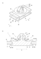
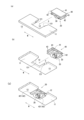
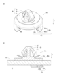
図1は第1実施形態のクリップ20をプロテクタ本体10に取付けたプロテクタ1の斜視図を示し、図2(a)は第1実施形態のクリップ20の斜視図を示し、図2(b)は取付状態のクリップ20の断面図を示している。図3(a)はクリップ20をプロテクタ本体10におけるスライド取付孔12に取付ける前の状態の上方からの斜視図を示し、図3(b)は同状態の下方からの斜視図を示し、図3(c)はクリップ20をスライド取付孔12に取付けた状態の下方からの斜視図を示している。
なお、図1において、プロテクタ本体10の内部空間13に挿通するワイヤーハーネスWHを透過状態で図示している。
Hereinafter, embodiments of the present invention will be described in detail based on the drawings.
FIG. 1 shows a perspective view of the
In addition, in FIG. 1, the wire harness WH inserted into the
プロテクタ1は、四角筒状のプロテクタ本体10におけるスライド取付孔12に、クリップ20を取付けて構成している。
プロテクタ本体10は、側面視略正方形状の倒位の四角筒状体であり、内部に長手方向Lに貫通する内部空間13を有している。この内部空間13は、ワイヤーハーネスWHを長手方向Lに挿通する空間である。
The
The protector
なお、図1に示すように、倒位の四角筒状であるプロテクタ本体10の長手方向を長手方向Lとし、長手方向Lに直交する方向を幅方向Wとしている。また、クリップ20がスライド取付孔12においてスライドする方向をスライド方向Sとしている。
As shown in FIG. 1, the longitudinal direction of the protector
プロテクタ本体10は、樹脂シートを折り曲げて構成している。詳述すると、側面視略正方形状の倒位の四角筒状体であるプロテクタ本体10は、各面を構成する部分が連続した樹脂シートを各辺部分で山折りし、一面を重ねて溶着して構成している。
なお、本実施形態では、上面部材11を重ねて構成しているが、一対の側面の一方を重ねて構成してもよいし、底面を重ねて構成してもよい。また、連続する複数面を重ねて構成してもよい。
The protector
In this embodiment, the
プロテクタ本体10を構成する熱可塑性樹脂発泡シートの密度は、特に限定されないが、例えば、機械的特性の異方性を防止、すなわち、機械的特性を等方化して、プロテクタ本体10の設計の自由度を向上させ、また、プロテクタ本体10に収容されたワイヤーハーネスWH方向への応力に対する強度をより向上させる点から、200Kg/m3以上1000Kg/m3以下が好ましく、軽量性と機械的強度とのバランスをより向上させる点から、300Kg/m3以上600Kg/m3以下がより好ましく、350Kg/m3以上550Kg/m3以下が特に好ましい。
The density of the thermoplastic resin foam sheet constituting the
プロテクタ本体10を構成する熱可塑性樹脂発泡シートの厚さは、特に限定されないが、例えば、折り曲げ容易性と機械的強度、特に、プロテクタ本体10に収容されたワイヤーハーネスWH方向への応力に対する機械的強度とのバランスをより向上させる点から、0.50mm以上4.0mm以下が好ましく、1.0mm以上2.5mm以下が特に好ましい。また、熱可塑性樹脂発泡シートには、両面または片面に、非発泡層が形成されていてもよい。すなわち、熱可塑性樹脂発泡シートは、発泡層と該発泡層上に形成された非発泡層とを有する構成としてもよい。熱可塑性樹脂発泡シートの表面に非発泡層が形成されていることにより、プロテクタ本体10の機械的強度が向上して、収容されるワイヤーハーネスWHの保護性能がより向上する。非発泡層の厚さは、特に限定されず、例えば、10μm以上100μm以下が挙げられる。
The thickness of the thermoplastic resin foam sheet constituting the protector
また、プロテクタ本体10を構成する熱可塑性樹脂発泡シートの発泡層の気泡数密度は、特に限定されず、その下限値は、機械的特性の異方性をより確実に防止する点から、800個/mm3以上が好ましく、1000個/mm3以上が特に好ましい。一方で、上記気泡数密度の上限値は、優れた機械的強度をより確実に得る点から、例えば、1010個/mm3以下を挙げることができる。
上述のような樹脂シートを折り曲げて構成したプロテクタ本体10の上面部材11を含む各面は板状に構成される。
Further, the cell number density of the foam layer of the thermoplastic resin foam sheet constituting the
Each surface of the protector
このように樹脂シートで構成された四角筒状であるプロテクタ本体10における上面部材11に複数のスライド取付孔12を、長手方向Lに所定間隔を隔てて複数設けている。本実施形態では2つのスライド取付孔12を設けているが、プロテクタ本体10の長さや、内部空間13に挿通するワイヤーハーネスWHの重量等の諸条件によって装着する適宜の数のクリップ20に対応する数のスライド取付孔12を設ければよい。
スライド取付孔12は、上面部材11の長手方向Lの両端部に設けられ、上面部材11を厚み方向に貫通する、平面視略長方形状の開口である。
As described above, a plurality of
The slide attachment holes 12 are provided at both ends of the
詳述すると、スライド取付孔12は、上面部材11の長手方向Lの両端部において、長手方向Lの外側が開口する、つまり長手方向Lの内側に向かって凹状となる、平面視角形U字状の開口である。
また、スライド取付孔12における開口側には、図3(a),(b)に示すように、開口に対して凹状となる位置決め凹部121を備えている。
To be more specific, the
Further, the opening side of the
上面部材11におけるスライド取付孔12に装着するクリップ20は、車両のエンジンルームなどの所定の装着箇所に設けたアンカー孔(図示省略)に挿着するアンカー部30と、スライド取付孔12に取付けるクリップ本体部40とで構成している。
The
アンカー部30は、アンカー部30をアンカー孔に装着した際に、車体パネルに押付けられる略皿状の皿部31と、皿部31の中央から延び、アンカー孔に挿入されて係止する挿入係止部32を有する。挿入係止部32の先端には、皿部31に向かって逆ハ字形に延びる係止アーム33を有する。このように構成されたアンカー部30は、アンカー部30をアンカー孔に装着した際に、係止アーム33が撓んでアンカー孔を通過し、皿部31と係止アーム33とで車体パネルを挟み込むように装着される。
The
クリップ本体部40は、平面視長方形で所定の高さに形成された台座部41と、台座部41の長軸側、つまり幅方向Wの両端部に、上下方向に間隔を隔てて配置するとともに、幅方向Wの外側に向かって突出するスライダ部42とで構成している。
The clip
台座部41は、上面部材11に設けたスライド取付孔12の開口幅よりわずかに小さな幅の平面視長方形状に形成されており、上面部材11の厚みより高く形成している。このように形成された台座部41の高さ方向の一方の面(図2(a)には上面)にアンカー部30を設けている。
The
スライダ部42は、台座部41の幅方向Wの両端部からそれぞれ突出するとともに、上下方向に間隔を隔てて配置されている一対のフランジ421で構成されている。
このように一対のフランジ421が上下方向に間隔を隔てて配置しているため、幅方向Wの外側に開放された横向きの角形U字状のスライダ部42を構成することができる。なお、フランジ421同士が上下方向に隔てる間隔は、スライド取付孔12を有する上面部材11の厚みに対応する間隔である。
The
Since the pair of
また、フランジ421を備えた台座部41の側面におけるスライダ部42を構成するフランジ421同士の間には、スライド方向Sの中央より一方側に、スライド取付孔12の位置決め凹部121に係止する係止凸部43を備えている。
Moreover, between the
台座部41の側面におけるスライド方向Sの中央より一方側に備えた係止凸部43は、スライド方向Sの他方側の面が幅方向Wの外側に向かって傾斜し、係止凸部43の一方側の面が幅方向Wに沿う面となる。このように構成された係止凸部43を有するクリップ20は、係止凸部43において傾斜する面が設けられたスライド方向Sの他方側がスライド取付孔12への挿入方向前側となり、係止凸部43が配置されたスライド方向Sの一方側が挿入方向後ろ側となる。なお、スライド方向Sとは、スライダ部42によって、スライド取付孔12をスライド挿入するスライド方向Sに沿う方向である。
The locking
このように構成したクリップ20は、図3(a),(b)に示すように、上面部材11のスライド取付孔12に対して、プロテクタ本体10の長手方向L(本実施形態では長手方向Lとスライド方向Sは同じ)の外側から装着する。
As shown in FIGS. 3(a) and 3(b), the
具体的には、プロテクタ本体10の長手方向Lの外側からスライド取付孔12に対し、スライダ部42でスライド取付孔12の周縁部を挟むようにスライド方向Sに挿入する。そして、スライド取付孔12の周縁部を上下から挟むスライダ部42をスライドさせる。クリップ20がスライド取付孔12における所定位置までスライドすると、係止凸部43が位置決め凹部121に係止し、図3(c)に示すように、スライド取付孔12の所定位置にクリップ20を取付けて、プロテクタ1を構成することができる。
Specifically, it is inserted into the
上述のようにプロテクタ本体10の上面部材11にクリップ20を取付けたプロテクタ1は、プロテクタ本体10の内部空間13に、ワイヤーハーネスWHを挿通させる。そして、内部空間13にワイヤーハーネスWHを挿通したプロテクタ1を、車両のエンジンルームなどの所定の装着箇所に設けたアンカー孔(図示省略)にクリップ20のアンカー部30を挿入してプロテクタ1を所定の装着箇所に装着することができる。これにより、プロテクタ1の内部空間13を挿通するワイヤーハーネスWHを所定の配索経路で配索できるとともに、内部空間13を挿通するワイヤーハーネスWHを保護することができる。
In the
このように、所定のアンカー孔に装着される、プロテクタ本体10と、プロテクタ本体10の上面部材11におけるスライド取付孔12に取付けられ、アンカー孔にプロテクタ本体10を装着するクリップ20とで構成されたプロテクタ1は、クリップ20に、スライド取付孔12に対して、上面部材11の板面に沿うスライド方向にスライドするスライダ部42が設けられ、スライダ部42によってスライド取付孔12の所定位置にスライドしたクリップ20の位置を固定する係止凸部43が設けられている。そのため、プロテクタ本体10におけるスライド取付孔12に取付けられたクリップ20が不用意に外れることを防止できる。
In this way, the
詳述すると、所定のアンカー孔に装着されるプロテクタ本体10の上面部材11におけるスライド取付孔12に取付けられ、アンカー孔にプロテクタ本体10を装着するクリップ20に、スライド取付孔12に対して、上面部材11の板面に沿うスライド方向にスライドするスライダ部42が設けられている。そして、スライダ部42によってスライド取付孔12の所定位置にスライドしたクリップ20の位置を係止凸部43が固定するため、プロテクタ本体10のスライド取付孔12における所定位置に安定してクリップ20を取付けることができる。したがって、クリップ20を介してプロテクタ本体10を所定のアンカー孔に正確に装着することができる。
To be more specific, the
また、スライダ部42によるスライド方向Sが、板面に沿うスライド方向における直線上の一方向であるため、板面に沿う直線上の一方向にスライダ部42をスライドさせて、容易にクリップ20をプロテクタ本体10におけるスライド取付孔12の所定位置に容易に取付けることができる。
Furthermore, since the sliding direction S by the
また、スライド取付孔12に凹状の位置決め凹部121が設けられるとともに、位置決め凹部121に係止する凸状の係止凸部43がクリップ20に設けられている。そのため、スライダ部42をスライド取付孔12の所定位置までスライドさせて、凹状の位置決め凹部121と、凸状の係止凸部43とを係止することで、スライド取付孔12に対してクリップ本体部40を位置固定できる。したがって、クリップ20をプロテクタ本体10におけるスライド取付孔12の所定位置に確実に取付けることができる。
また、プロテクタ本体10は、軽量であるとともに、加工性が高い樹脂シートで構成されているため、所望のスライド取付孔12を形成することができる。
Further, a
Furthermore, since the protector
また、プロテクタ本体10は、加工性が高い板状の樹脂シートを折り曲げて構成された立体構造体であるため、所望の立体形状のプロテクタ本体10を簡易に構成することができる。
Moreover, since the protector
続いて、第2実施形態の取付孔12aについて図4とともに説明する。
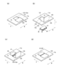
なお、図4(a)はクリップ20をプロテクタ本体10における第2実施形態の取付孔12aに取付ける前の状態の斜視図を示し、図4(b)はクリップ20を第2実施形態の取付孔12aに取付けた状態の斜視図を示している。なお、後述する挿入孔部123にクリップ本体部40を挿入する方向を挿入方向Iとする。
Next, the
Note that FIG. 4(a) shows a perspective view of the
以下の説明において、取付孔12aにおいて上述のスライド取付孔12と同じ構成については、同じ符号を付してその説明を省略し、取付孔12aにおいてスライド取付孔12と異なる構成について詳細に説明する。
In the following description, the same components in the mounting
第2実施形態は、上述の実施形態におけるクリップ20と同じものを用いるが、取付孔12aが上述の実施形態のスライド取付孔12と異なる。
具体的には、第2実施形態の取付孔12aは、上述の実施形態のスライド取付孔12と同じように、位置決め凹部121を有し、クリップ本体部40をスライドさせて取付けるスライド孔部122と、クリップ本体部40を挿入方向Iに移動させて挿入する挿入孔部123とが連通した開口である。
The second embodiment uses the
Specifically, the
詳しくは、上面部材11の長手方向Lの両端部に、長手方向Lの外側に開口するスライド取付孔12に対し、取付孔12aは上面部材11における任意の位置に設けられている。
取付孔12aは、位置決め凹部121を有するスライド孔部122に対し、スライド孔部122に向かってクリップ20のクリップ本体部40をスライドさせて取付けるスライド方向Sの後ろ側に挿入孔部123が配置されるとともに、相互に連通する一体の開口を形成している。
Specifically, the attachment holes 12a are provided at arbitrary positions in the
The
挿入孔部123は、スライダ部42を含む台座部41よりわずかに大きな相似形の開口である。そのため、スライド孔部122より幅方向Wが長い長方形状の開口となる。
また、挿入孔部123には、挿入孔部123を閉塞する閉塞カバー124を、挿入孔部123の周縁部における辺部分に設けたヒンジ125によって枢動可能に設けている。
閉塞カバー124は、挿入孔部123の内部に嵌め込んで挿入孔部123を閉塞するためのカバーである。
The
Further, a
The
このように構成された取付孔12aに対して、スライド取付孔12の上方からクリップ20を装着する。
詳しくは、スライド取付孔12の上方らクリップ20のクリップ本体部40を挿入方向Iに移動させて挿入孔部123に挿入する。そして、取付孔12aを構成する挿入孔部123に挿入されたクリップ本体部40のスライダ部42でスライド孔部122の周縁部を上下方向から挟むようにしてスライド孔部122の内部においてスライド方向Sにスライドさせて取付ける。
The
Specifically, the clip
スライド孔部122において所定位置までスライドさせると、係止凸部43が、スライド孔部122の位置決め凹部121と係止して、クリップ20を取付孔12aのスライド孔部122に取付けることができる。このように、取付孔12aの所定位置までクリップ20がスライドすると、挿入孔部123が開放される。そのため、ヒンジ125を軸として、閉塞カバー124を枢動させて、挿入孔部123に閉塞カバー124を嵌め込んで挿入孔部123を閉塞する。
When the
このように構成されたクリップ20aは、上述の第1実施形態のクリップ20における作用効果に加え、上面部材11に、スライダ部42を上面部材11の板面に交差する挿入方向Iから挿入する挿入孔部123と、挿入孔部123から挿入されたスライダ部42がスライド可能な、スライド方向Sに延びるスライド孔部122とが設けられている。そのため、挿入孔部123に挿入したスライダ部42を、スライド孔部122をスライドさせてスライド取付孔12の所定位置にクリップ20を取付けることができる。
In addition to the effects of the
また、挿入孔部123とスライド孔部122とが連通して取付孔12aを構成しているため、挿入孔部123に挿入したスライダ部42を、スライド孔部122をスライド方向Sに向かってスライドさせてスライド取付孔12の所定位置にクリップ20を取付ける動作を一連動作で行うことができる。したがって、クリップ20をスライド取付孔12の所定位置に容易に取付けることができる。
Furthermore, since the
また、挿入孔部123を塞ぐ閉塞カバー124が設けられているため、挿入孔部123から挿入したスライダ部42を、スライド孔部122をスライドさせてスライド取付孔12の所定位置に取付けた後、挿入孔部123を閉塞カバー124が塞ぐことができる。そのため、スライダ部42がスライド孔部122をスライドして不用意にスライド取付孔12の所定位置からクリップ20が脱落することを防止できる。
Further, since a
また、閉塞カバー124は、プロテクタ本体10(11)に設けられるとともに、挿入孔部123を塞ぐ閉塞位置と挿入孔部123を開放する開放位置とを枢動可能に閉塞カバー124を支持するヒンジ125が設けられている。そのため、ヒンジ125によって開放位置に閉塞カバー124を開放した状態で挿入孔部123からスライダ部42を挿入方向Iに挿入する。挿入孔部123から挿入したスライダ部42を、スライド孔部122をスライドさせてスライド取付孔12の所定位置に取付ける。その後、ヒンジ125によって閉塞カバー124を開放位置から閉塞位置に枢動させることで挿入孔部123を閉塞カバー124が確実に塞ぐことができる。また、閉塞カバー124がヒンジ125によって連結されているため、閉塞カバー124が不用意に脱落することを防止できる。
Further, the
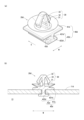
続いて、第3実施形態のクリップ20bについて図5及び図6とともに説明する。
なお、図5(a)は第3実施形態のクリップ20bの斜視図を示し、図5(b)は取付状態のクリップ20bの断面図を示している。図6(a)はクリップ20bをプロテクタ本体10におけるスライド取付孔12bに取付ける前の状態の斜視図を示し、図6(b)はクリップ20bをスライド取付孔12bに取付けた状態の斜視図を示している。
Next, a
Note that FIG. 5(a) shows a perspective view of the
以下の説明においても、クリップ20bにおいて上述のクリップ20と同じ構成については、同じ符号を付してその説明を省略し、クリップ20bにおいてクリップ20と異なる構成及びスライド取付孔12bについて詳細に説明する。
In the following description, the same components of the
クリップ20bは、アンカー部30と、クリップ本体部40bとで構成している。
クリップ本体部40bは、平面視長方形で板状の台座部41bと、台座部41bの幅方向Wの両端部に備えたスライダ部42bと、位置決め凸部43bで構成している。
The
The clip
台座部41bは、幅方向Wに長い平面視長方形状の板状に形成されている。
スライダ部42bは、平面視長方形状の台座部41bの幅方向Wの両端部から下方(アンカー部30が配置された側と反対側)に延びる側壁部421bと、側壁部421bの下端から幅方向Wの内側に向かって延びるフランジ部422bとで正面視略L字状に構成している。
The
The
なお、フランジ部422bは、台座部41bに対してスライド取付孔12bを備えた上面部材11bの厚みに対応する間隔で配置している。このように構成されたスライダ部42bは、上述の実施形態1のスライダ部42が幅方向Wの外側に向かって設けられたのに対して、幅方向Wの内側に向かうように構成されている。
Note that the
位置決め凸部43bは、図6(a)に示すように、台座部41bの底面(アンカー部30が配置された面の反対面)の略中心付近に設けられ、下方に突出する凸状である。
位置決め凸部43bは、スライド方向Sの前側に傾斜する傾斜面を有している。
As shown in FIG. 6A, the positioning
The positioning
このように構成されたクリップ本体部40bをスライドさせてクリップ20bを取付けるスライド取付孔12bは、図6(a)に示すように、幅方向Wの両端部に備えた一対のスライダ部42bに対応して2つの位置決め凹部121bが備えられている。
The slide attachment holes 12b to which the
位置決め凹部121bは、スライダ部42bをスライド方向Sにスライドさせて取付けるスライド孔部122bと、クリップ本体部40を挿入する挿入孔部123bとが連通した開口であり、一対構成された位置決め凹部121bは対称な向きで配置している。
フランジ部422bが挿入方向Iに通過する挿入孔部123bは、スライド孔部122bより幅広に形成され、挿入孔部123bとスライド孔部122bとは、幅方向Wの外側が直線状となるように一体化している。
The
The
また、一対の挿入孔部123bの間には、位置決め凸部43bがスライドするスライド方向Sに延びる凸部スライド溝124bと、挿入孔部123bのスライド方向Sの前方に所定間隔を隔てて、位置決め凸部43bが嵌合して、スライド取付孔12bの所定位置にクリップ本体部40bを規制する位置決め孔125bを設けている。
Further, between the pair of
このように構成されたスライド取付孔12bに対して、クリップ本体部40bをスライド取付孔12bに挿入して、上面部材11bに対してクリップ20bを取付ける。
詳しくは、上面部材11bの上方から挿入方向Iに沿ってクリップ20bのスライダ部42bを挿入孔部123bに挿入する。このとき、位置決め凸部43bは、凸部スライド溝124bに挿入される。そして、スライド取付孔12bを構成するスライド孔部122bに向けてスライダ部42bをスライド方向Sにスライドさせる。また、位置決め凸部43bも凸部スライド溝124bをスライド方向Sにスライドさせる。側壁部421bがスライド孔部122bの所定位置までスライドすると、位置決め凸部43bは凸部スライド溝124bを越えて位置決め孔125bに嵌合して、その位置を固定することができる。このようにして、クリップ本体部40bを備えたクリップ20bを、スライド取付孔12bを有する上面部材11bの所定位置に取付けることができる。
The clip
Specifically, the
このように構成されたクリップ20bは、上述の第1実施形態のクリップ20における作用効果に加え、スライダ部42bをスライド取付孔12bの所定位置までスライドさせて、スライド取付孔12bに設けられた位置決め孔125bに、クリップ20に設けられた位置決め凸部43bを嵌合することで、位置固定できる。したがって、クリップ20をプロテクタ本体10におけるスライド取付孔12の所定位置に確実に取付けることができる。
In addition to the effects of the
また、上面部材11に、スライダ部42を板面に交差する挿入方向Iから挿入する挿入孔部123と、挿入孔部123から挿入されたスライダ部42がスライド可能な、スライド方向Sに延びるスライド孔部122と、スライド方向Sに延びる凸部スライド溝124bとが設けられている。また、凸部スライド溝124bは、位置決め凸部43bがスライド方向Sに挿入され、且つ移動可能であり、凸部スライド溝124bのスライド方向Sの先端側に、位置決め孔125bが配置されている。
Further, the
そのため、挿入孔部123からスライダ部42を挿入し、スライド孔部122をスライド方向Sにスライドさせることで、位置決め凸部43bも凸部スライド溝124bをスライドする。そして、スライド取付孔12bの所定位置までスライダ部42がスライドすると、凸部スライド溝124bのスライド方向Sの先端側に配置された位置決め孔125bに位置決め凸部43bを嵌合することができる。したがって、クリップ20bをプロテクタ本体10におけるスライド取付孔12の所定位置に確実に取付けることができる。
Therefore, by inserting the
また、スライダ部42及びスライド孔部122がスライド方向Sに交差する幅方向Wに2組、設けられているため、複数箇所でスライダ部42がスライド孔部122にスライド可能に係止する。そのため、より安定した取付状態を構成することができる。
Further, since two sets of the
続いて、第4実施形態のクリップ20cについて図7及び図8とともに説明する。
なお、図7(a)は第4実施形態のクリップ20cの斜視図を示し、図7(b)は取付状態のクリップ20cの断面図を示している。図8(a)はクリップ20cをプロテクタ本体10におけるスライド取付孔12cに取付ける前の状態の斜視図を示し、図8(b)はクリップ20cをスライド取付孔12cに取付けた状態の斜視図を示している。
Next, a
Note that FIG. 7(a) shows a perspective view of a
以下の説明においても、クリップ20cにおいて上述のクリップ20と同じ構成については、同じ符号を付してその説明を省略し、クリップ20cにおいてクリップ20と異なる構成及びスライド取付孔12cについて詳細に説明する。
クリップ20cは、アンカー部30と、平面視円形のクリップ本体部40cとで構成している。
In the following description, the same components in the
The
クリップ本体部40cは、平面視円形板状の円形台座部41cと、円形台座部41cにおける周方向一部に形成するとともに、対向する一対の回転スライダ42cとで構成している。
The clip
回転スライダ42cは、平面視円形状の円形台座部41cの外周縁の一部から下方(アンカー部30が配置された側と反対側)に延びる平面視円弧状の側壁部421cと、側壁部421cの下端から径内側に向かって延びるフランジ部422cとで断面略L字状に構成している。なお、回転スライダ42cは、1/4円程度の長さで形成され、周方向に対向する2箇所に設けている。
The
なお、フランジ部422cは、円形台座部41cに対してスライド取付孔12cを備えた上面部材11cの厚みに対応する間隔で配置している。また、上述のように断面L字状に構成されたフランジ部422cにおいて、円弧状の側壁部421cの一方向の端部に、側壁部421cとフランジ部422cとを跨ぐ規制壁43cを備えている。なお、本実施形態において、アンカー部30が配置された側から視て時計回りの回転スライド方向Srにスライドさせるため、規制壁43cは、側壁部421cにおける時計回り後ろ側の端部に設けられている。
Note that the
このように構成されたクリップ本体部40cを回転スライド方向Srにスライドさせてクリップ20cを取付けるスライド取付孔12cは、図8(a)に示すように、上面部材11cにおいて、略半円状に形成されるとともに、対称な向きで配置されている。
スライド取付孔12cにおける周方向の中央付近には、規制壁43cが係止する位置決め凹部121cを備えている。
The
Near the center of the
なお、スライド取付孔12cにおける平面視時計回り前側(回転スライド方向Srの前側)に配置され、回転スライダ42cが回転スライド方向Srにスライドする半円状のスライド溝122cと、スライド取付孔12cにおいて平面視時計回り(スライド方向S)の後側に配置され、回転スライダ42cが挿入される挿入溝123cとで構成している。
スライド溝122cと挿入溝123cとは、径外側が連続する円弧状となるが、フランジ部422cが挿入方向Iに通過する挿入溝123cが溝幅はスライド溝122cより太く形成されている。
Note that a
The
このように構成されたスライド取付孔12cに対して、クリップ本体部40cをスライド取付孔12cに挿入して、上面部材11cに対してクリップ20cを取付ける。
詳しくは、上面部材11cの上方からクリップ20cの回転スライダ42cを挿入溝123cに挿入方向Iから挿入する。そして、スライド取付孔12cを構成するスライド溝122cに向けて回転スライダ42cを時計回り(回転スライド方向Sr)に回転スライドさせる。
The clip
Specifically, the
側壁部421cがスライド溝122cの所定位置まで回転スライドすると、規制壁43cはスライド溝122cに嵌合して、その位置を固定することができる。このようにして、クリップ本体部40cを備えたクリップ20cを、スライド取付孔12cを有する上面部材11cの所定位置に取付けることができる。
When the
このように構成されたクリップ20cは、上述の第1実施形態のクリップ20における作用効果に加え、回転スライダ42cによる回転スライド方向Srが、板面に沿うスライド方向において、所定の回転軸を中心とした回転方向である。そのため、板面に沿う回転スライド方向Srに回転スライダ42cをスライドさせてプロテクタ本体10におけるスライド取付孔12の所定位置にクリップ20cを取付けることができる。また、挿入孔部123にプロテクタ本体10を装着した装着状態において作用する振動等によって回転スライダ42cが不用意にスライドして、取付状態が予期せず解消され、挿入孔部123からプロテクタ本体10が脱落することを予防できる。
In addition to the effects of the
続いて、第5実施形態のクリップ20dについて図9及び図10とともに説明する。
なお、図9(a)は第5実施形態のクリップ20dの斜視図を示し、図9(b)は取付状態のクリップ20dの断面図を示している。図10(a)はクリップ20dをプロテクタ本体10におけるスライド取付孔12dに取付ける前の状態の斜視図を示し、図10(b)はクリップ20dをスライド取付孔12dに取付けた状態の斜視図を示している。
Next, a
Note that FIG. 9(a) shows a perspective view of a
以下の説明においても、クリップ20dにおいて上述のクリップ20と同じ構成については、同じ符号を付してその説明を省略し、クリップ20dにおいてクリップ20と異なる構成及びスライド取付孔12dについて詳細に説明する。
クリップ20dは、アンカー部30と、クリップ本体部40dとで構成している。
In the following description, the same components in the
The
クリップ本体部40dは、平面視略正方形状で板状の台座部41dと、スライダ部42dとで構成している。
スライダ部42dは、平面視正方形状の台座部41dの幅方向Wの中央から下方(アンカー部30が配置された側と反対側)に延びる中央壁部421dと、中央壁部421dの下端から幅方向Wの両外側に向かって延びるフランジ部422dとで正面視略逆T字状に構成している。
The clip
The
なお、フランジ部422dは、台座部41dに対してスライド取付孔12dを備えた上面部材11dの厚みに対応する間隔で配置している。
このように構成されたスライダ部42dにおける中央壁部421dの両側面には、それぞれ側方に突出する凸状である位置決め凸部423dを備えている。
The
Both sides of the
このように構成されたクリップ本体部40dをスライドさせてクリップ20dを取付けるスライド取付孔12dは、図10(a)に示すように、スライダ部42dを回転スライド方向Srにスライドさせて取付けるスライド孔部122dと、クリップ本体部40を挿入方向Iに挿入する挿入孔部123dとが連通した開口である。
As shown in FIG. 10(a), the
フランジ部422dが挿入方向Iに通過する挿入孔部123dは、スライド孔部122dより幅広に形成されている。
また、スライド孔部122dにおける挿入孔部123dの側の近傍には、両側面から凹状となり、位置決め凸部423dが係止する位置決め凹部121dを設けている。
The
In addition, a
このように構成されたスライド取付孔12dに対して、クリップ本体部40dをスライド取付孔12dに挿入して、上面部材11dに対してクリップ20dを取付ける。
詳しくは、上面部材11dの上方からクリップ20dのスライダ部42dを挿入方向Iに移動して挿入孔部123dに挿入する。そして、挿入孔部123dから、スライド孔部122dに向けてスライダ部42dをスライドさせる。
The clip
Specifically, the
中央壁部421dがスライド孔部122dの所定位置までスライドすると、位置決め凸部423dは位置決め凹部121dに嵌合して、その位置を固定することができる。このようにして、クリップ本体部40dを備えたクリップ20dを、スライド取付孔12dを有する上面部材11dの所定位置に取付けることができる。
When the
このように構成されたクリップ20dは、上述の第1実施形態のクリップ20における作用効果に加え、上面部材11に、スライダ部42dを上面部材11の板面に交差する挿入方向Iから挿入する挿入孔部123dと、挿入孔部123dから挿入されたスライダ部42dがスライド可能な、スライド方向Sに延びるスライド孔部122dとが設けられている。そのため、挿入孔部123dに挿入したスライダ部42dを、スライド孔部122dをスライド方向Sにスライドさせてスライド取付孔12dの所定位置にクリップ20dを取付けることができる。
In addition to the effects of the
また、挿入孔部123dとスライド孔部122dとが連通してスライド取付孔12dを構成しているため、挿入孔部123dに挿入したスライダ部42dを、スライド孔部122dをスライド方向Sに向かってスライドさせてスライド取付孔12dの所定位置にクリップ20dを取付ける動作を一連動作で行うことができる。したがって、クリップ20dをスライド取付孔12dの所定位置に容易に取付けることができる。
In addition, since the
続いて、第6実施形態のクリップ20eについて図11及び図12とともに説明する。
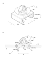
なお、図11(a)は第6実施形態のクリップ20eの上方からの斜視図を示し、図11(b)は第6実施形態のクリップ20eの下方からの斜視図を示し、図11(c)は取付状態のクリップ20eの断面図を示している。また、図12(a)はクリップ20eをプロテクタ本体10におけるスライド取付部12eに取付ける前の状態の下方からの斜視図を示し、図12(b)はクリップ20eをスライド取付部12eに取付けた状態の下方からの斜視図を示している。
Next, a
Note that FIG. 11(a) shows a perspective view from above of the
以下の説明においても、クリップ20eにおいて上述のクリップ20と同じ構成については、同じ符号を付してその説明を省略し、クリップ20eにおいてクリップ20と異なる構成及びスライド取付部12eについて詳細に説明する。
In the following description, the same components of the
クリップ20eは、アンカー部30と、クリップ本体部40eとで構成している。
クリップ本体部40eは、平面視長方形状の所定の高さで構成した直方体状の台座部41eで構成している。
The
The clip
台座部41eは、上面411eと、底面412eと、上面411e及び底面412eを上下方向に連結する平面視三方向に配置した側面413eとで中空の箱状を構成している。台座部41eにおけるスライド方向Sの一方の側面部分にスライド開口414eを形成している。
The
底面412eの幅方向中央付近には、スライド開口414eの側が支持された位置規制弾性片415eを備えている。位置規制弾性片415eの上面側には、後述するスライド取付部12eの位置決め孔121eに嵌合する嵌合凸部43eを備えている。
A position regulating
上面411eと底面412eとは、スライド取付部12eを有する上面部材11eの厚みより広い間隔を隔てて配置されている。上面411eの底面には、上下方向に対向する底面412eに向かって突出するとともに、スライド方向Sに沿って延びるスライド凸部42eを備えている。
The
このように構成されたクリップ本体部40eをスライドさせてクリップ20eを取付けるスライド取付部12eは、図12(a)に示すように、上面部材11eの端部に形成され、台座部41eの側面413eに対応するスライドスリット122eが両側に形成されて、平面視長方形状に形成されている。なお、スライド取付部12eの内部には、台座部41eの嵌合凸部43eが嵌合する位置決め孔121eが設けられている。スライドスリット122eは台座部41eの側面413eの厚みより幅広い間隔のスリットである。
As shown in FIG. 12(a), the
このように構成されたスライド取付部12eに対して、クリップ本体部40eをスライド方向Sに移動させて、スライド取付部12eに挿入して、上面部材11eに対してクリップ20eを取付ける。
詳しくは、台座部41eの側面413eをスライド取付部12eの両側のスライドスリット122eに挿入する。このとき、スライド取付部12eはスライド開口414eから嵌合凸部43eの内部に挿入される。嵌合凸部43eの内部に挿入されたスライド取付部12eは、上面411eの底面に備えたスライド凸部42eと底面412eとに上下方向から挟まれた状態でスライドする。
With respect to the
Specifically, the
さらに、スライド取付部12eに対してクリップ20eを所定位置までスライドさせると、嵌合凸部43eが位置規制弾性片415eの付勢力に抗してスライド取付部12eの端部を乗り越え、位置決め孔121eに嵌合して、その位置を固定することができる。このようにして、クリップ本体部40eを備えたクリップ20eを、スライド取付部12eを有する上面部材11eの所定位置に取付けることができる。
Furthermore, when the
このように構成されたクリップ20eは、上述の第1実施形態のクリップ20における作用効果に加え、スライド凸部42eをスライド取付部12eの所定位置までスライドさせて、スライド取付部12eに設けられた位置決め孔121eに、クリップ20eに設けられた凸状の嵌合凸部43eを嵌合することで、位置固定できる。したがって、クリップ20eをプロテクタ本体10におけるスライド取付部12eの所定位置に確実に取付けることができる。
In addition to the effects of the
この発明の構成と、上述の実施形態との対応において、この発明の装着箇所はアンカー孔に対応し、
以下同様に、
板状部は上面部材11,11a,11b,11c,11d,11eに対応し、
被装着部材はプロテクタ本体10に対応し、
係止部品はクリップ20,20b,20c,20d,20eに対応し、
スライド部はスライダ部42に対応し、
位置固定部及び係止部は係止凸部43,43d又は規制壁43cに対応し、
被装着部材の固定構造はプロテクタ1に対応し、
被係止部は位置決め凹部121,121b,121c,121dに対応し、
嵌合孔部は位置決め孔125b,121eに対応し、
嵌合凸部は位置決め凸部43b又は嵌合凸部43eに対応し、
挿入孔は挿入孔部123,123b,123d又は挿入溝123cに対応し、
スライド孔はスライド孔部122,122b,122d又はスライド溝122cに対応し、
凸部移動孔は凸部スライド溝124bに対応し、
カバー部は閉塞カバー124に対応し、
塞ぎ位置は閉塞位置に対応し、
開放位置は開放位置に対応し、
ヒンジ部はヒンジ125に対応するも、この発明は、上述の実施形態の構成のみに限定されるものではなく、多くの実施の形態を得ることができる。
In the correspondence between the configuration of this invention and the above-described embodiments, the mounting location of this invention corresponds to the anchor hole,
Similarly below,
The plate-shaped portions correspond to the
The member to be attached corresponds to the protector
The locking parts correspond to the
The slide portion corresponds to the
The position fixing part and the locking part correspond to the locking
The fixing structure of the attached member corresponds to the
The locked portions correspond to the positioning recesses 121, 121b, 121c, and 121d,
The fitting holes correspond to the positioning holes 125b and 121e,
The fitting protrusion corresponds to the
The insertion hole corresponds to the
The slide hole corresponds to the
The convex part moving hole corresponds to the convex
The cover portion corresponds to the
The occluded position corresponds to the occluded position,
The open position corresponds to the open position,
Although the hinge portion corresponds to the
なお、上述の説明では、プロテクタ本体10の上面部材11に設けたスライド取付孔12にクリップ20を取付けたが、プロテクタ本体10の側面や底面にクリップ20を取付けてもよい。さらには、プロテクタ本体10の異なる面にクリップ20を取付けてもよい。
In the above description, the
プロテクタ本体10は、倒位の四角筒状であったが、扁平な長方形断面の四角筒状や三角筒状などの多角筒状体であってもよいし、円筒状であってもよい。さらには、断面角形U字状断面であっても、断面L字状であってもよい。
また、係止凸部43をクリップ20に備え、位置決め凹部121をスライド取付孔12に形成したが、係止凸部をスライド取付孔12に備え、位置決め凹部をクリップ20に形成してもよい。
Although the protector
Further, although the
また、上述の第2実施形態の説明では、スライド孔部122と挿入孔部123とが連通した開口である取付孔12aにおいて、挿入孔部123を閉塞する閉塞カバー124を、挿入孔部123の周縁部における辺部分に設けたヒンジ125によって枢動可能に設けたが、閉塞カバー124がクリップ20に設けられてもよいし、閉塞カバー124をクリップ20や取付孔12aと別体でもうけてもよい。
In addition, in the above description of the second embodiment, in the
また、スライダ部42は、樹脂シートで構成されたプロテクタ本体10を構成する上面部材11の厚み方向の内部に食い込んでスライドしてもよい。この場合、取付状態において、スライダ部42がプロテクタ本体10の肉厚内部に喰込むため、クリップ20の取付状態をより安定させることができる。
Further, the
1…プロテクタ
10…プロテクタ本体
11,11a,11b,11c,11d,11e…上面部材
20,20a,20b,20c,20d,20e…クリップ
42,42b,42c,42d,42e…スライダ部
43,43d…係止凸部
43b…位置決め凸部
43c…規制壁
43e…嵌合凸部
121…位置決め凹部
122,122b,122d…スライド孔部
122c…スライド溝
123,123b,123d…挿入孔部
123c…挿入溝
124…閉塞カバー
124b…凸部スライド溝
125…ヒンジ
125b…位置決め孔
1...
Claims (13)
該板状部における取付箇所に取付けられ、前記装着箇所に前記被装着部材を装着する係止部品とで構成され、
前記係止部品に、前記取付箇所に対して、前記板状部の板面に沿うスライド方向にスライドするスライド部が設けられ、
前記スライド部によって前記取付箇所の所定位置にスライドした前記係止部品の位置を固定する位置固定部が設けられ、
前記被装着部材は、樹脂シートで構成され、
前記スライド部は、
前記樹脂シートで構成された前記被装着部材の厚み方向の内部に食い込んでスライドする
被装着部材の固定構造。 an attached member having a plate-like portion that is attached to a predetermined attachment location;
a locking part that is attached to an attachment point in the plate-shaped part and that attaches the member to be attached to the attachment point;
The locking component is provided with a sliding portion that slides in a sliding direction along the plate surface of the plate-like portion with respect to the attachment location,
A position fixing part is provided for fixing the position of the locking component that has been slid to a predetermined position of the attachment location by the slide part ,
The mounted member is made of a resin sheet,
The slide part is
It slides into the inside of the attached member made of the resin sheet in the thickness direction.
Fixing structure for attached parts.
請求項1に記載の被装着部材の固定構造。 The fixing structure for a mounted member according to claim 1, wherein the sliding direction of the sliding portion is one direction on a straight line in the sliding direction along the plate surface.
請求項1に記載の被装着部材の固定構造。 2. The fixing structure for a mounted member according to claim 1, wherein the sliding direction of the sliding portion is a rotating direction about a predetermined rotation axis in a sliding direction along the plate surface.
前記取付箇所及び前記係止部品の一方に設けられた凹状の被係止部と、
前記取付箇所及び前記係止部品の他方に設けられ、前記被係止部に係止する凸状の係止部とで構成された
請求項1乃至請求項3のうちいずれかに記載の被装着部材の固定構造。 The position fixing part is
a concave locked portion provided at one of the attachment location and the locking component;
The attachment target according to any one of claims 1 to 3, comprising a convex locking part that is provided on the other side of the attachment part and the locking part and that locks on the locked part. Fixed structure of members.
前記取付箇所及び前記係止部品の一方に設けられた嵌合孔部と、
前記取付箇所及び前記係止部品の他方に設けられ、前記嵌合孔部に嵌合する凸状の嵌合凸部とで構成された
請求項1乃至請求項3のうちいずれかに記載の被装着部材の固定構造。 The position fixing part is
a fitting hole provided in one of the attachment location and the locking component;
The cover according to any one of claims 1 to 3, comprising a fitting convex portion provided on the other side of the attachment portion and the locking part and fitting into the fitting hole portion. Fixing structure for mounting parts.
前記スライド部を前記板面に交差する方向から挿入する挿入孔と、
該挿入孔から挿入された前記スライド部がスライド可能な、前記スライド方向に延びるスライド孔と、
前記スライド方向に延びる凸部移動孔とが設けられ、
前記凸部移動孔は、前記嵌合凸部が前記スライド方向に挿入され、且つ移動可能であり、
前記凸部移動孔の前記スライド方向の先端側に、前記嵌合孔部が配置された
請求項5に記載の被装着部材の固定構造。 In the plate-shaped part,
an insertion hole into which the slide portion is inserted from a direction intersecting the plate surface;
a slide hole extending in the sliding direction, into which the slide portion inserted through the insertion hole can slide;
a protrusion moving hole extending in the sliding direction;
The fitting protrusion is inserted into the protrusion moving hole and movable in the sliding direction,
6. The fixing structure for a mounted member according to claim 5, wherein the fitting hole portion is disposed on a distal end side of the convex portion moving hole in the sliding direction.
前記スライド部を前記板面に交差する方向から挿入する挿入孔と、
該挿入孔から挿入された前記スライド部がスライド可能な、前記スライド方向に延びるスライド孔とが設けられた
請求項1乃至請求項4のうちいずれかに記載の被装着部材の固定構造。 In the plate-shaped part,
an insertion hole into which the slide portion is inserted from a direction intersecting the plate surface;
5. The fixing structure for a mounted member according to claim 1, further comprising a slide hole extending in the sliding direction, into which the slide portion inserted through the insertion hole can slide.
請求項6又は請求項7に記載の被装着部材の固定構造。 The fixing structure for a mounted member according to claim 6 or 7, wherein the insertion hole and the slide hole communicate with each other.
請求項6乃至請求項8のうちいずれかに記載の被装着部材の固定構造。 The fixing structure for a mounted member according to any one of claims 6 to 8, further comprising a cover portion that closes the insertion hole.
前記挿入孔を塞ぐ塞ぎ位置と前記挿入孔を開放する開放位置とを枢動可能に前記カバー部を支持するヒンジ部が設けられた
請求項9に記載の被装着部材の固定構造。 The cover part is provided on the mounted member, and
10. The fixing structure for a mounted member according to claim 9, further comprising a hinge portion that supports the cover portion so as to be pivotable between a closed position for closing the insertion hole and an open position for opening the insertion hole.
請求項6乃至請求項10のうちいずれかに記載の被装着部材の固定構造。 The fixing structure for a mounted member according to any one of claims 6 to 10, wherein a plurality of the slide portions and the slide holes are provided in a direction intersecting the slide direction.
請求項1に記載の被装着部材の固定構造。 The mounted member is a three-dimensional structure formed by bending the plate-shaped resin sheet.
A fixing structure for a mounted member according to claim 1 .
前記取付箇所に対して、前記板状部の板面に沿うスライド方向にスライドするスライド部と、
前記取付箇所の所定位置にスライドした前記スライド部の位置を固定する位置固定部とが設けられ、
前記被装着部材は、樹脂シートで構成され、
前記スライド部は、
前記樹脂シートで構成された前記被装着部材の厚み方向の内部に食い込んでスライドする
係止部品。 A locking component that is attached to a mounting location on the plate-like part of a member to be mounted having a plate-shaped part, which is mounted to a predetermined mounting location, and for mounting the member to be mounted to the mounting location,
a sliding portion that slides in a sliding direction along the plate surface of the plate-like portion with respect to the attachment location;
a position fixing part for fixing the position of the slide part slid to a predetermined position of the attachment point ;
The mounted member is made of a resin sheet,
The slide part is
It slides into the inside of the attached member made of the resin sheet in the thickness direction.
Locking parts.
Priority Applications (1)
| Application Number | Priority Date | Filing Date | Title |
|---|---|---|---|
| JP2020043536A JP7449727B2 (en) | 2020-03-12 | 2020-03-12 | Fixing structure and locking parts for attached parts |
Applications Claiming Priority (1)
| Application Number | Priority Date | Filing Date | Title |
|---|---|---|---|
| JP2020043536A JP7449727B2 (en) | 2020-03-12 | 2020-03-12 | Fixing structure and locking parts for attached parts |
Publications (2)
| Publication Number | Publication Date |
|---|---|
| JP2021145498A JP2021145498A (en) | 2021-09-24 |
| JP7449727B2 true JP7449727B2 (en) | 2024-03-14 |
Family
ID=77767470
Family Applications (1)
| Application Number | Title | Priority Date | Filing Date |
|---|---|---|---|
| JP2020043536A Active JP7449727B2 (en) | 2020-03-12 | 2020-03-12 | Fixing structure and locking parts for attached parts |
Country Status (1)
| Country | Link |
|---|---|
| JP (1) | JP7449727B2 (en) |
Families Citing this family (1)
| Publication number | Priority date | Publication date | Assignee | Title |
|---|---|---|---|---|
| JP2025150473A (en) * | 2024-03-27 | 2025-10-09 | 住友電装株式会社 | protector |
Citations (10)
| Publication number | Priority date | Publication date | Assignee | Title |
|---|---|---|---|---|
| JP2003032853A (en) | 2001-07-12 | 2003-01-31 | Sumitomo Wiring Syst Ltd | Mounting structure of grommet |
| JP2007282480A (en) | 2006-03-17 | 2007-10-25 | Furukawa Electric Co Ltd:The | Wire harness clamp |
| JP2009030804A (en) | 2007-07-03 | 2009-02-12 | Daiwa Kasei Ind Co Ltd | Two-member fastening structure |
| JP2011043230A (en) | 2009-08-24 | 2011-03-03 | Daikyonishikawa Corp | Clip attaching structure |
| JP2012186986A (en) | 2011-02-15 | 2012-09-27 | Sumitomo Wiring Syst Ltd | Wire holder and wire holding structure |
| JP2013013230A (en) | 2011-06-29 | 2013-01-17 | Auto Network Gijutsu Kenkyusho:Kk | Wiring tool and wire harness |
| JP2013241971A (en) | 2012-05-18 | 2013-12-05 | Piolax Inc | Clip |
| JP2016059101A (en) | 2014-09-05 | 2016-04-21 | 株式会社オートネットワーク技術研究所 | Electric wire module |
| JP2017055510A (en) | 2015-09-08 | 2017-03-16 | 株式会社オートネットワーク技術研究所 | Wire Harness |
| WO2019131848A1 (en) | 2017-12-28 | 2019-07-04 | 古河電気工業株式会社 | Exterior body for wire and a wire harness with exterior body |
Family Cites Families (4)
| Publication number | Priority date | Publication date | Assignee | Title |
|---|---|---|---|---|
| JPS58146110U (en) * | 1982-03-26 | 1983-10-01 | 加藤発条株式会社 | locking device |
| JPS59107319U (en) * | 1983-01-11 | 1984-07-19 | ソニー株式会社 | Rotation fixing device |
| JPH071521Y2 (en) * | 1990-11-30 | 1995-01-18 | 豊田合成株式会社 | Resin product clip assembly structure |
| JP2559515Y2 (en) * | 1991-12-16 | 1998-01-19 | 株式会社ニフコ | Mounting clip fixing structure |
-
2020
- 2020-03-12 JP JP2020043536A patent/JP7449727B2/en active Active
Patent Citations (10)
| Publication number | Priority date | Publication date | Assignee | Title |
|---|---|---|---|---|
| JP2003032853A (en) | 2001-07-12 | 2003-01-31 | Sumitomo Wiring Syst Ltd | Mounting structure of grommet |
| JP2007282480A (en) | 2006-03-17 | 2007-10-25 | Furukawa Electric Co Ltd:The | Wire harness clamp |
| JP2009030804A (en) | 2007-07-03 | 2009-02-12 | Daiwa Kasei Ind Co Ltd | Two-member fastening structure |
| JP2011043230A (en) | 2009-08-24 | 2011-03-03 | Daikyonishikawa Corp | Clip attaching structure |
| JP2012186986A (en) | 2011-02-15 | 2012-09-27 | Sumitomo Wiring Syst Ltd | Wire holder and wire holding structure |
| JP2013013230A (en) | 2011-06-29 | 2013-01-17 | Auto Network Gijutsu Kenkyusho:Kk | Wiring tool and wire harness |
| JP2013241971A (en) | 2012-05-18 | 2013-12-05 | Piolax Inc | Clip |
| JP2016059101A (en) | 2014-09-05 | 2016-04-21 | 株式会社オートネットワーク技術研究所 | Electric wire module |
| JP2017055510A (en) | 2015-09-08 | 2017-03-16 | 株式会社オートネットワーク技術研究所 | Wire Harness |
| WO2019131848A1 (en) | 2017-12-28 | 2019-07-04 | 古河電気工業株式会社 | Exterior body for wire and a wire harness with exterior body |
Also Published As
| Publication number | Publication date |
|---|---|
| JP2021145498A (en) | 2021-09-24 |
Similar Documents
| Publication | Publication Date | Title |
|---|---|---|
| JP7449727B2 (en) | Fixing structure and locking parts for attached parts | |
| CN105531892B (en) | Harness bending is restricted component and the harness laying structure of component is restricted using harness bending | |
| JP5892604B2 (en) | Arm feeder | |
| JP6445431B2 (en) | Vehicle door lining and its mounting structure | |
| JP5286736B2 (en) | Grommet | |
| JP2014023247A (en) | Arm power supply | |
| CN104471811A (en) | Arm power supply device | |
| JPH1198659A (en) | Harness assembly structure for vehicle floor | |
| JP7449728B2 (en) | Fixing structure and locking parts for attached parts | |
| JP2006226394A (en) | Clamp | |
| JP4931694B2 (en) | Wire harness clamp | |
| JP2020015466A (en) | Attachment device of vehicle interior member | |
| JP3046749B2 (en) | Protector | |
| JP3772724B2 (en) | Wiring harness wiring structure | |
| CA3152706A1 (en) | Access panel with encased spring | |
| JP2007252059A (en) | Harness protector harness assembly structure | |
| JP2008230260A (en) | Combination clamp | |
| JP7266001B2 (en) | Wiring harness clamp structure | |
| JP2022112598A (en) | Protector and wire harness arrangement structure | |
| CN223237546U (en) | Z-shaped semi-fixed wire harness trend fixing support | |
| JP7624211B2 (en) | Roller device and sliding door | |
| JP2007159272A (en) | Clamp mounting structure to flexible flat cable | |
| JP2024113340A (en) | Route control member and electric wire with control member | |
| JP2593148Y2 (en) | Receiver for noise absorber and noise absorber | |
| JPH11308739A (en) | Cable bundle fixing clip |
Legal Events
| Date | Code | Title | Description |
|---|---|---|---|
| A621 | Written request for application examination |
Free format text: JAPANESE INTERMEDIATE CODE: A621 Effective date: 20230124 |
|
| A977 | Report on retrieval |
Free format text: JAPANESE INTERMEDIATE CODE: A971007 Effective date: 20230821 |
|
| A131 | Notification of reasons for refusal |
Free format text: JAPANESE INTERMEDIATE CODE: A131 Effective date: 20230926 |
|
| A521 | Request for written amendment filed |
Free format text: JAPANESE INTERMEDIATE CODE: A523 Effective date: 20231124 |
|
| TRDD | Decision of grant or rejection written | ||
| A01 | Written decision to grant a patent or to grant a registration (utility model) |
Free format text: JAPANESE INTERMEDIATE CODE: A01 Effective date: 20240220 |
|
| A61 | First payment of annual fees (during grant procedure) |
Free format text: JAPANESE INTERMEDIATE CODE: A61 Effective date: 20240304 |
|
| R151 | Written notification of patent or utility model registration |
Ref document number: 7449727 Country of ref document: JP Free format text: JAPANESE INTERMEDIATE CODE: R151 |