JP7488024B2 - Humerus nail - Google Patents
Humerus nail Download PDFInfo
- Publication number
- JP7488024B2 JP7488024B2 JP2018506806A JP2018506806A JP7488024B2 JP 7488024 B2 JP7488024 B2 JP 7488024B2 JP 2018506806 A JP2018506806 A JP 2018506806A JP 2018506806 A JP2018506806 A JP 2018506806A JP 7488024 B2 JP7488024 B2 JP 7488024B2
- Authority
- JP
- Japan
- Prior art keywords
- hole
- nail
- proximal
- screw
- humeral
- Prior art date
- Legal status (The legal status is an assumption and is not a legal conclusion. Google has not performed a legal analysis and makes no representation as to the accuracy of the status listed.)
- Active
Links
- 210000002758 humerus Anatomy 0.000 title claims description 39
- 210000000988 bone and bone Anatomy 0.000 claims description 12
- 210000004095 humeral head Anatomy 0.000 claims description 11
- 230000008685 targeting Effects 0.000 claims description 7
- 210000004233 talus Anatomy 0.000 claims description 3
- 230000001174 ascending effect Effects 0.000 description 12
- 230000008901 benefit Effects 0.000 description 8
- 210000003484 anatomy Anatomy 0.000 description 4
- 238000000034 method Methods 0.000 description 3
- 210000005036 nerve Anatomy 0.000 description 3
- 238000012986 modification Methods 0.000 description 2
- 230000004048 modification Effects 0.000 description 2
- 210000000653 nervous system Anatomy 0.000 description 2
- 230000002792 vascular Effects 0.000 description 2
- 208000007981 Humeral Fractures Diseases 0.000 description 1
- 206010020462 Humerus fracture Diseases 0.000 description 1
- 208000027418 Wounds and injury Diseases 0.000 description 1
- 238000010276 construction Methods 0.000 description 1
- 230000006378 damage Effects 0.000 description 1
- 238000010586 diagram Methods 0.000 description 1
- 208000014674 injury Diseases 0.000 description 1
- 238000003780 insertion Methods 0.000 description 1
- 230000037431 insertion Effects 0.000 description 1
- 210000000115 thoracic cavity Anatomy 0.000 description 1
Images


Classifications
-
- A—HUMAN NECESSITIES
- A61—MEDICAL OR VETERINARY SCIENCE; HYGIENE
- A61B—DIAGNOSIS; SURGERY; IDENTIFICATION
- A61B17/00—Surgical instruments, devices or methods
- A61B17/56—Surgical instruments or methods for treatment of bones or joints; Devices specially adapted therefor
- A61B17/58—Surgical instruments or methods for treatment of bones or joints; Devices specially adapted therefor for osteosynthesis, e.g. bone plates, screws or setting implements
- A61B17/68—Internal fixation devices, including fasteners and spinal fixators, even if a part thereof projects from the skin
- A61B17/72—Intramedullary devices, e.g. pins or nails
- A61B17/7233—Intramedullary devices, e.g. pins or nails with special means of locking the nail to the bone
- A61B17/725—Intramedullary devices, e.g. pins or nails with special means of locking the nail to the bone with locking pins or screws of special form
-
- A—HUMAN NECESSITIES
- A61—MEDICAL OR VETERINARY SCIENCE; HYGIENE
- A61B—DIAGNOSIS; SURGERY; IDENTIFICATION
- A61B17/00—Surgical instruments, devices or methods
- A61B17/56—Surgical instruments or methods for treatment of bones or joints; Devices specially adapted therefor
- A61B17/58—Surgical instruments or methods for treatment of bones or joints; Devices specially adapted therefor for osteosynthesis, e.g. bone plates, screws or setting implements
- A61B17/68—Internal fixation devices, including fasteners and spinal fixators, even if a part thereof projects from the skin
- A61B17/72—Intramedullary devices, e.g. pins or nails
- A61B17/7233—Intramedullary devices, e.g. pins or nails with special means of locking the nail to the bone
-
- A—HUMAN NECESSITIES
- A61—MEDICAL OR VETERINARY SCIENCE; HYGIENE
- A61B—DIAGNOSIS; SURGERY; IDENTIFICATION
- A61B17/00—Surgical instruments, devices or methods
- A61B17/56—Surgical instruments or methods for treatment of bones or joints; Devices specially adapted therefor
- A61B17/58—Surgical instruments or methods for treatment of bones or joints; Devices specially adapted therefor for osteosynthesis, e.g. bone plates, screws or setting implements
- A61B17/68—Internal fixation devices, including fasteners and spinal fixators, even if a part thereof projects from the skin
- A61B2017/681—Alignment, compression, or distraction mechanisms
Landscapes
- Health & Medical Sciences (AREA)
- Orthopedic Medicine & Surgery (AREA)
- Surgery (AREA)
- Life Sciences & Earth Sciences (AREA)
- Heart & Thoracic Surgery (AREA)
- Nuclear Medicine, Radiotherapy & Molecular Imaging (AREA)
- Engineering & Computer Science (AREA)
- Biomedical Technology (AREA)
- Neurology (AREA)
- Medical Informatics (AREA)
- Molecular Biology (AREA)
- Animal Behavior & Ethology (AREA)
- General Health & Medical Sciences (AREA)
- Public Health (AREA)
- Veterinary Medicine (AREA)
- Surgical Instruments (AREA)
- Prostheses (AREA)
Description
関連出願の相互参照
本願は、2015年4月24日に提出された米国仮出願第62/152339号の利益を主張するものであり、同仮出願は、参照によりその全体が本明細書中に援用される。
CROSS-REFERENCE TO RELATED APPLICATIONS This application claims the benefit of U.S. Provisional Application No. 62/152,339, filed April 24, 2015, which is incorporated herein by reference in its entirety.
上腕骨骨折の治療に上腕骨用釘を使用する際、主要血管系や神経系を避けると共に、上腕骨頭近辺にある特定の解剖学的ランドマークを効果的に標的とできることが重要である。各患者の解剖学的構造における大きさや形状は異なるため、特定の解剖学的標的は患者によりその場所が異なる。従来の一部の上腕骨用釘は患者の解剖学的ランドマークを効果的に標的とすることができなかった(従来技術として、米国特許出願公開第2007/123873号明細書、独国実用新案第2021316号明細書、及び、米国特許出願公開第2009/157078号明細書参照)。 When using humeral nails to treat humeral fractures, it is important to be able to effectively target specific anatomical landmarks near the humeral head while avoiding major vascular and nervous systems. Since each patient's anatomy is different in size and shape, the specific anatomical targets are located in different locations from patient to patient. Some prior art humeral nails have been unable to effectively target the patient's anatomical landmarks (see prior art US 2007/123873, DE 2021316, and US 2009/157078) .
本明細書で開示される器具をより良く説明するため、以下に実施例を非限定的に列挙する。 To better illustrate the devices disclosed herein, the following non-limiting examples are provided:
実施例1において、釘本体の近位部から遠位部に延びる釘長手軸線を定める釘本体と、釘本体内部に形成され、孔出口に対して前方で近位に位置する孔入口を有し、釘本体を通って前方から後方への下降ねじ軌道を定める下降貫通孔とを含む上腕骨用釘が提供される。 In Example 1, a humerus nail is provided that includes a nail body that defines a nail longitudinal axis extending from a proximal portion to a distal portion of the nail body, and a descending through hole formed within the nail body, having a hole inlet located anterior and proximal to the hole outlet, and defining a descending thread trajectory from anterior to posterior through the nail body.
実施例2において、実施例1の上腕骨用釘は、下降貫通孔が患者の小結節を標的にするために骨ねじを収容するよう任意で構成される。 In Example 2, the humeral nail of Example 1 is optionally configured with a descending bore to accommodate a bone screw for targeting the patient's tuberosity.
実施例3において、実施例1又は実施例2の上腕骨用釘は、下降貫通孔が上腕骨用釘の近位部を通って延びるよう任意で構成される。 In Example 3, the humeral nail of Example 1 or Example 2 is optionally configured such that the descending through hole extends through a proximal portion of the humeral nail.
実施例4において、実施例1~3のいずれかの上腕骨用釘は、釘本体を通って下降ねじ軌道に交差する上昇ねじ軌道を定める上昇貫通孔を任意で更に含む。 In Example 4, the humerus nail of any of Examples 1-3 optionally further includes an elevation through hole that defines an elevation screw trajectory that passes through the nail body and intersects with the descending screw trajectory.
実施例5において、実施例4の上腕骨用釘は、上昇ねじ軌道と下降ねじ軌道のなす角度が近位-遠位方向に少なくとも40°であるよう任意で構成される。 In Example 5, the humeral nail of Example 4 is optionally configured such that the angle between the ascending screw trajectory and the descending screw trajectory is at least 40° in the proximal-distal direction.
実施例6において、上腕骨用釘は、釘本体の近位部から釘本体の遠位部に延びる釘長手軸線を定める釘本体と、釘本体内に形成され、釘長手軸線を横切って延びる第1のねじ軌道を定める第1の近位貫通孔と、釘本体内に形成され、釘長手軸線を横切って延びる第2のねじ軌道を定める第2の近位貫通孔と、釘本体内に形成され、釘長手軸線を横切って延びる第3のねじ軌道を定める第3の近位貫通孔と、釘本体内に形成され、前方から後方及び近位から遠位に延びる下降ねじ軌道を定める下降貫通孔と、及び、釘本体内に形成され、前方から後方、外側から内側、及び遠位から近位に延びる距ねじ軌道を定める距貫通孔とを含む。 In Example 6, the humerus nail includes a nail body defining a nail longitudinal axis extending from a proximal portion of the nail body to a distal portion of the nail body, a first proximal through hole formed in the nail body defining a first thread trajectory extending across the nail longitudinal axis, a second proximal through hole formed in the nail body defining a second thread trajectory extending across the nail longitudinal axis, a third proximal through hole formed in the nail body defining a third thread trajectory extending across the nail longitudinal axis, a descending through hole formed in the nail body defining a descending thread trajectory extending from anterior to posterior and proximal to distal, and a distal through hole formed in the nail body defining a distal thread trajectory extending from anterior to posterior, lateral to medial, and distal to proximal.
実施例7において、実施例6の上腕骨用釘は、第1、第2、及び第3の近位貫通孔、下降貫通孔、及び距貫通孔が、釘本体の近位部を通って延びるよう任意で構成される。 In Example 7, the humeral nail of Example 6 is optionally configured such that the first, second, and third proximal through holes, the descending through hole, and the calcar through hole extend through the proximal portion of the nail body.
実施例8において、実施例6又は実施例7の上腕骨用釘は、第1の近位貫通孔が第1のねじ軌道が内側-外側軸線に沿って外側から内側に延びることを定めるよう任意で構成される。 In Example 8, the humeral nail of Example 6 or Example 7 is optionally configured such that the first proximal through hole defines a first thread trajectory extending from lateral to medial along a medial-lateral axis.
実施例9において、実施例6~8のいずれかの上腕骨用釘は、第2の近位貫通孔が第2のねじ軌道が外側から内側及び後方から前方に延びることを定めるよう任意で構成される。 In Example 9, the humeral nail of any of Examples 6-8 is optionally configured such that the second proximal through hole defines a second thread trajectory extending from lateral to medial and posterior to anterior.
実施例10において、実施例6~9のいずれかの上腕骨用釘は、第3の近位貫通孔が第3のねじ軌道が外側から内側及び前方から後方に延びることを定めるよう任意で構成される。 In Example 10, the humeral nail of any of Examples 6-9 is optionally configured such that the third proximal through hole defines a third thread trajectory extending from lateral to medial and anterior to posterior.
実施例11において、実施例6~10のいずれかの上腕骨用釘は、距貫通孔が角度可変距ねじ軌道を定めるよう任意で構成される。 In Example 11, the humeral nail of any of Examples 6-10 is optionally configured such that the calcar through hole defines a variable angle calcar screw trajectory.
実施例12において、実施例6~11のいずれかの上腕骨用釘は、釘本体内に形成され、前方から後方、遠位から近位に延びる上昇ねじ軌道を定める上昇貫通孔を任意で更に含む。 In Example 12, the humeral nail of any of Examples 6 to 11 optionally further includes an elevation through hole formed within the nail body that defines an elevation screw trajectory extending from anterior to posterior and distal to proximal.
実施例13において、上腕骨用釘は、上腕骨用釘本体の近位部から遠位部に延びる釘長手軸線を定める上腕骨用釘本体と、上腕骨用釘本体を通って延び、孔出口に対して前方及び外側に位置する孔入口を有する距貫通孔とを含み、距貫通孔は遠位から近位に延びる少なくとも2つの異なる距ねじ軌道を定める。 In Example 13, the humeral nail includes a humeral nail body defining a nail longitudinal axis extending from a proximal portion to a distal portion of the humeral nail body, and a calcar through hole extending through the humeral nail body and having a hole inlet located anteriorly and laterally relative to the hole outlet, the calcar through hole defining at least two distinct calcar screw trajectories extending distally to proximally.
実施例14において、実施例13の上腕骨用釘は、孔入口が2つの交差長円を含むよう任意で構成される。 In Example 14, the humeral nail of Example 13 is optionally configured such that the hole entrance includes two intersecting ellipses.
実施例15において、実施例13又は実施例14の上腕骨用釘は、少なくとも2つの異なる距ねじ軌道が近位-遠位方向及び内側-外側方向において異なるよう任意で構成される。 In Example 15, the humeral nail of Example 13 or Example 14 is optionally configured with at least two different talar screw trajectories that differ in the proximal-distal direction and the medial-lateral direction.
実施例16において、実施例13~15の上腕骨用釘は、孔入口が数字の8の字状の開口を含むよう任意で構成される。 In Example 16, the humeral nail of Examples 13-15 is optionally configured such that the hole entrance includes a figure eight shaped opening.
実施例17において、実施例13~16のいずれかの上腕骨用釘は、距貫通孔が少なくとも3つの異なる距ねじ軌道を定めるよう任意で構成される。 In Example 17, the humeral nail of any of Examples 13-16 is optionally configured such that the calcar through hole defines at least three different calcar screw trajectories.
実施例18において、実施例13~17のいずれかの上腕骨用釘は、孔入口が3つの交差長円を含むよう任意で構成される。 In Example 18, the humerus nail of any of Examples 13-17 is optionally configured such that the hole entrance includes three intersecting ellipses.
実施例19において、実施例13~18のいずれかの上腕骨用釘は、異なる距ねじ軌道のそれぞれが釘長手軸線から40°~60°の角度で延びるよう任意で構成される。 In Example 19, the humerus nail of any of Examples 13-18 is optionally configured such that each of the different talar screw trajectories extends at an angle between 40° and 60° from the nail longitudinal axis.
実施例20において、実施例13~19のいずれかの上腕骨用釘は、孔入口が内側-外側軸線から前方に約50°の角度で配置され、孔出口が内側-外側軸線から後方に約50°の角度で配置されるよう任意で構成される。 In Example 20, the humeral nail of any of Examples 13-19 is optionally configured such that the hole inlet is disposed at an angle of approximately 50° anterior to the medial-lateral axis and the hole outlet is disposed at an angle of approximately 50° posterior to the medial-lateral axis.
実施例21において、実施例1~20のいずれか一つ、又は、いずれかの組み合わせの装置、システム、又は方法は、上述した全ての要素又は任意の要素を使用可能又は選択可能なように任意で構成できる。 In Example 21, the device, system, or method of any one or any combination of Examples 1 to 20 can be optionally configured to use or select all or any of the elements described above.
本装置、システム、及び方法の上記及びその他の実施例や特徴は、その一部が以下の「発明を実施するための形態」に規定される。本概要は、本特許出願の主題の概説を提供することを意図している。本「発明を実施するための形態」は、本特許出願の更なる情報を提供するために含まれる。 These and other embodiments and features of the present devices, systems, and methods are defined in part in the Detailed Description below. This Summary is intended to provide an overview of the subject matter of this patent application. This Detailed Description is included to provide further information about this patent application.
図面は必ずしも実物大に描かれたものではないが、異なる図面間の同様の数字は同様の構成要素を表すことがある。同様の数字が異なる接尾文字を有する場合、同様の構成要素の異なるインスタンスを表すことがある。概して、図面は一例として非限定的に本明細書で解説される各種実施例を描写する。 The drawings are not necessarily drawn to scale, but like numerals between different drawings may represent like components. Like numerals with different letter suffixes may represent different instances of like components. Generally, the drawings depict, by way of example and not by way of limitation, various embodiments discussed herein.
上腕骨用釘は、近位部から遠位部に延びる釘長手軸線を定める釘本体を含むことがある。一部の実施例では、上腕骨用釘の近位部は、例えば、下降貫通孔、距貫通孔、及び複数の近位貫通孔などの、釘本体を通って形成された複数の貫通孔を含む。一部の実施例では、下降貫通孔は前方から後方及び近位から遠位に延びる下降ねじ軌道を定めることがある。一部の実施例では、上腕骨用釘は、下降ねじ軌道に交差する上昇ねじ軌道を定める上昇貫通孔を更に含むことがある。一部の実施例では、距貫通孔は角度可変距ねじ軌道を定めることがある。 The humeral nail may include a nail body defining a nail longitudinal axis extending from a proximal portion to a distal portion. In some embodiments, the proximal portion of the humeral nail includes a plurality of through holes formed therethrough, such as, for example, a descending through hole, a calcaneal through hole, and a plurality of proximal through holes. In some embodiments, the descending through hole may define a descending screw trajectory extending from anterior to posterior and proximal to distal. In some embodiments, the humeral nail may further include an ascending through hole defining an ascending screw trajectory that intersects the descending screw trajectory. In some embodiments, the calcaneal through hole may define a variable angle calcaneal screw trajectory.
少なくとも一つの実施例では、上腕骨用釘は、重要な血管系や神経系を避けながら、上腕骨頭近辺の解剖学的ランドマークを標的にしたねじ軌道を提供することがある。更に、上腕骨用釘を通るこれらねじ軌道によって安定した固定性能が提供されるが、これはねじが不良骨質に埋め込まれる場合に特に重要となる。少なくとも一つの実施例では、上腕骨用釘は、患者特異的な解剖学的ランドマークを標的にすることを可能にするねじ軌道を提供することができる。 In at least one embodiment, the humeral nail may provide screw trajectories that target anatomical landmarks near the humeral head while avoiding important vascular and nervous systems. Additionally, these screw trajectories through the humeral nail provide stable fixation performance, which is particularly important when the screws are embedded in poor bone quality. In at least one embodiment, the humeral nail may provide screw trajectories that allow for targeting of patient-specific anatomical landmarks.
一部の実施例では、下降ねじ軌道は患者の小結節を標的にできる。少なくとも一つの実施例では、従来の前方から後方へのねじ軌道は釘長手軸線を横切って延び一部の患者に対しては低すぎて小結節を捉えられないことがあったが、下降ねじ軌道は小結節をより効果的に標的にすることができる。 In some embodiments, the descending screw trajectory can target the patient's nodules. In at least one embodiment, the descending screw trajectory can more effectively target the nodules than a conventional anterior-to-posterior screw trajectory that extends across the nail's longitudinal axis and may be too low for some patients to capture the nodules.
一部の実施例では、角度可変距ねじ軌道は、上腕骨頭の距領域を標的にすることがある。少なくとも一つの実施例では、従来の固定軌道システムに比べて、角度可変距ねじ軌道は患者特定の距領域をより効果的に標的にすることができる。 In some embodiments, a variable-angle calcaneal screw trajectory may target the calcaneal region of the humeral head. In at least one embodiment, a variable-angle calcaneal screw trajectory may more effectively target a patient-specific calcaneal region as compared to a conventional fixed trajectory system.
その他の適用可能分野は、本明細書に提供される説明から明確になるであろう。本発明の概要中の説明や特定の実施例は描写の目的のみが意図されており、本開示の範囲を限定することは意図されない。本明細書中で「横切って」という言葉は、概して「法線として」又は「直行して」と置き換え可能である。近位、遠位、内側、外側、前、後、という言葉は、上腕骨用釘が患者の上腕骨に埋め込まれる際の上腕骨用釘の向きに関して説明するものである。図1A~図2Fは、軸線の向きの方位記号を含み、「P」は近位軸線、「D」は遠位軸線、「M」は内側軸線、「L」は外側軸線、「A」は前方軸線、「B」は後方軸線を示す。 Other areas of applicability will become apparent from the description provided herein. The descriptions and specific examples in this Summary of the Invention are intended for illustrative purposes only and are not intended to limit the scope of the present disclosure. In this specification, the term "across" is generally interchangeable with "normally" or "orthogonally." The terms proximal, distal, medial, lateral, anterior, and posterior are used to describe the orientation of the humeral nail as it is implanted into the patient's humerus. Figures 1A-2F include arrowheads for the orientation of the axes, where "P" indicates the proximal axis, "D" the distal axis, "M" the medial axis, "L" the lateral axis, "A" the anterior axis, and "B" the posterior axis.
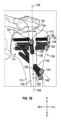
図1Aは、本開示の少なくとも一つの実施例に係わる、上腕骨用釘100の前面図である。上腕骨用釘100は、近位端104と遠位端106とを有する上腕骨用釘本体102を含み、上腕骨用釘本体102は上腕骨用釘本体102の長さに沿って近位端104から遠位端106まで延びる釘長手軸線108を定める。図例では、上腕骨用釘本体102が患者の上腕骨110内に埋め込まれている様子が描かれており、概して上腕骨頭112や距領域114を含む。
1A is a front view of a
一部の実施例では、上腕骨用釘本体102は、上腕骨用釘本体102内に形成され、遠位部106を通って延びる一以上の遠位貫通孔116、118を含むことがある。各遠位貫通孔116、118は遠位ねじ軌道120、122を定める。少なくとも1つの実施例では、一以上の遠位貫通孔116、118は、遠位ねじ軌道120、122を定めることがあり、釘長手軸線108を横切って延びる。一部の実施例では、一以上の遠位貫通孔116、118のそれぞれは、上腕骨用釘本体102の遠位部106を通って、いずれかの角度でいずれかの方向に延びる遠位ねじ軌道120、122を定めることがある。図例では、2つの遠位貫通孔116、118が描かれるが、他の実施例では、上腕骨用釘本体102が遠位貫通孔を含まない場合、遠位貫通孔を一つ含む場合、又は、遠位貫通孔を3つ以上含む場合がある。
In some embodiments, the
図1Bは、本開示の少なくとも一つの実施例に係わる、図1Aの上腕骨用釘100の近位部104の拡大図である。少なくとも一つの実施例では、上腕骨用釘本体102は第1の近位貫通孔124と、第2の近位貫通孔126と、第3の近位貫通孔128とを含むことがあり、近位貫通孔124、126、128のそれぞれは近位部104を通って延び、各貫通孔は上腕骨用釘本体102内に形成される。
1B is an enlarged view of the
少なくとも1つの実施例では、第1の近位貫通孔124は、上腕骨用釘本体102の最も近位にある貫通孔であってもよい。一部の実施例では、第1の近位貫通孔124は、上腕骨用釘本体102の近位端130から約10mm~15mm遠位に位置することがある。少なくとも一つの実施例では、第1の近位貫通孔124は上腕骨用釘本体102の近位端130から約12.5mm遠位に位置することがある。一部の実施例では、第1の近位貫通孔124は、近位部104を通って延びる第1のねじ軌道132を定めることがある。少なくとも一つの実施例では、第1のねじ軌道132は釘長手軸線108を横切って延びることがある。少なくとも一つの実施例では、第1のねじ軌道132は内側-外側軸線に沿って、外側から内側に延びることがある。
In at least one embodiment, the first proximal through
少なくとも1つの実施例では、第2の近位貫通孔126は、上腕骨用釘本体102の2番目に近位にある貫通孔であってもよい。一部の実施例では、第2の近位貫通孔126は、上腕骨用釘本体102の近位端130から約17mm~21mm遠位に位置することがある。少なくとも一つの実施例では、第2の近位貫通孔126は、上腕骨用釘本体102の近位端130から約19mm離れて位置することがある。一部の実施例では、第2の近位貫通孔126は、近位部104を通って延びる第2のねじ軌道134を定めることがある。少なくとも一つの実施例では、第2のねじ軌道134は釘長手軸線108を横切って延びることがある。少なくとも一つの実施例では、第2のねじ軌道134は外側から内側及び後方から前方に延びることがある。
In at least one embodiment, the second proximal through
少なくとも1つの実施例では、第3の近位貫通孔128は、上腕骨用釘本体102の3番目に近位にある貫通孔であってもよい。一部の実施例では、第3の近位貫通孔128は、上腕骨用釘本体102の近位端130から約23mm~28mm遠位に位置することがある。少なくとも一つの実施例では、第3の近位貫通孔128は上腕骨用釘本体102の近位端130から約25.5mm離れて位置することがある。一部の実施例では、第3の近位貫通孔128は、近位部104を通って延びる第3のねじ軌道136を定めることがある。少なくとも一つの実施例では、第3のねじ軌道136は釘長手軸線108を横切って延びることがある。少なくとも一つの実施例では、第3のねじ軌道136は外側から内側及び前方から後方に延びることがある。
In at least one embodiment, the third proximal through
他の実施例では、上腕骨用釘本体102はより多くの近位貫通孔、より少ない近位貫通孔を含むことがあり、それぞれの近位貫通孔はいずれの位置でいずれの向きでもよい。
In other embodiments, the
一部の実施例では、上腕骨用釘本体102は近位部104を通って延びる下降貫通孔138を含むことがある。少なくとも1つの実施例では、下降貫通孔138は、上腕骨用釘本体102の4番目に近位にある貫通孔であってもよい。一部の実施例では、下降貫通孔138は、上腕骨用釘本体102の近位端130から約30mm~34mm遠位に位置することがある。一部の実施例では、下降貫通孔138は、上腕骨用釘本体102の近位端130から約32mm遠位に位置することがある。一部の実施例では、下降貫通孔138は、近位部104を通って延びる下降ねじ軌道140を定めることがある。少なくとも一つの実施例では、下降ねじ軌道140は前方から後方及び近位から遠位に延びることがある。
In some embodiments, the
一部の実施例では、上腕骨用釘本体102は近位部104を通って延びる距貫通孔142を含むことがある。少なくとも1つの実施例では、距貫通孔142は、上腕骨用釘本体102の5番目に近位にある貫通孔であってもよい。一部の実施例では、距貫通孔142は、上腕骨用釘本体102の近位端130から約45mm~50mm遠位に位置することがある。少なくとも一つの実施例では、距貫通孔142は上腕骨用釘本体102の近位端130から約47.5mm離れて位置することがある。
In some embodiments, the
一部の実施例では、距貫通孔142は、近位部104を通って延びる一以上の距ねじ軌道144、146を定めることがある。一部の実施例では、一以上の距ねじ軌道144、146のそれぞれは、角度可変軌道からなることがある。一部の実施例では、距貫通孔142は、少なくとも2つの距ねじ軌道144、146を定めることがある。一部の実施例では、距貫通孔142は、少なくとも3つの距ねじ軌道を定めることがある。少なくとも一つの実施例では、距ねじ軌道140は前方から後方、外側から内側、そして遠位から近位に延びることがある。少なくとも一つの実施例では、距ねじ軌道140は釘長手軸線108又は近位-遠位軸線に対して、様々な角度180、182を有する。少なくとも一つの実施例では、距ねじ軌道144、146のそれぞれは、釘長手軸線108から40°~60°の角度で延びることがある。少なくとも一つの実施例では、一つの距ねじ軌道146の角度180は釘長手軸線108から40°であり、別の距ねじ軌道144の角度182は釘長手軸線108から60°であってもよい。一部の実施例では、距貫通孔142は、複数の軌道を可能にする可変距ねじ軌道144、146を提供するように長円又はその他の扁平開口からなることがある。少なくとも一つの実施例では、距貫通孔142はねじが40°から60°のいずれかの角度で配置されるのを可能にする。
In some embodiments, the talar through
図1Cは、本開示の少なくとも一つの実施例に係わる、図1Aと図1Bの上腕骨用釘100の上面図である。図例では、上腕骨用釘本体102が内腔148を形成することがある。少なくとも一つの実施例では、内腔148は釘長手軸線108に沿って、上腕骨用釘本体102の長さだけ延びることがある。
1C is a top view of the
図例に見られるように、第1のねじ軌道132はおおよそ内側-外側軸線に沿って、外側から内側に延びることがある。一部の実施例では、第2のねじ軌道134は外側から内側、後方から前方に延びることがある。少なくとも一つの実施例では、第2のねじ軌道134は内側-外側軸線から後方に角度150で延びることがある。少なくとも一つの実施例では、第2のねじ軌道134の角度150は、内側-外側軸線の後方に約30°であってもよい。少なくとも一つの実施例では、第2のねじ軌道134は、内側-外側平面の後方に約25°~30°の冠状面角度で延びることがある。
As seen in the illustrated example, the
一部の実施例では、第3のねじ軌道136は外側から内側及び前方から後方に延びることがある。少なくとも一つの実施例では、第3のねじ軌道136は内側-外側軸線の前方に角度152で延びることがある。少なくとも一つの実施例では、第3のねじ軌道136の角度152は、内側-外側軸線の前方に約25°であってもよい。少なくとも一つの実施例では、第3のねじ軌道136は、内側-外側平面の前方に約20°~30°の冠状面角度で延びることがある。
In some embodiments, the
一部の実施例では、下降ねじ軌道140は近位から遠位及び前方から後方に延びることがある。少なくとも一つの実施例では、下降ねじ軌道140は近位から遠位、前方から後方、内側から外側に延びることがある。少なくとも一つの実施例では、下降ねじ軌道140は内側-外側軸線の前方に角度154で延びることがある。少なくとも一つの実施例では、下降ねじ軌道140の角度154は、内側-外側軸線の前方に約95°であってもよい。少なくとも一つの実施例では、下降ねじ軌道140は、釘長手軸線108から約60°~80°の角度で前-後方向に延びることがある。
In some embodiments, the descending
一部の実施例では、一以上の距ねじ軌道144、146は、前方から後方、外側から内側、及び遠位から近位に延びることがある。少なくとも一つの実施例では、一以上の距ねじ軌道144、146は、内側-外側軸線の前方に角度156で延びることがある。少なくとも一つの実施例では、一以上の距ねじ軌道144、146の角度156は、内側-外側軸線の前方に約50°であってもよい。少なくとも一つの実施例では、一以上の距ねじ軌道144、146は、釘長手軸線108から約45°~60°の角度で前-後方向に延びる。
In some embodiments, the one or more talar screw tracks 144, 146 may extend from anterior to posterior, lateral to medial, and distal to proximal. In at least one embodiment, the one or more talar screw tracks 144, 146 may extend at an
少なくとも一つの実施例では、一以上の距ねじ軌道144、146は、内側-外側軸線から約45°~55°の冠状面角度、及び、釘長手軸線108から約40°~60°の角度で延びる。少なくとも一つの実施例では、角度可変距ねじ軌道は、釘長手軸線108から約40°、約50°、約60°で釘本体102内に位置することがある。少なくとも一つの実施例では。少なくとも一つの実施例では、角度可変距ねじ軌道は、釘長手軸線108から約40°及び内側-外側軸線から約35°~40°の冠状面角度、釘長手軸線108から約50°及び内側-外側軸線から約50°の冠状面角度、また、釘長手軸線108から約60°の角度及び内側-外側軸線から約60°~65°の冠状面角度、で釘本体102内に位置することがある。
In at least one embodiment, the one or more talar screw tracks 144, 146 extend at a coronal angle of about 45° to 55° from the medial-lateral axis and at an angle of about 40° to 60° from the nail
図例では、第1の近位貫通孔124、第2の近位貫通孔126、第3の近位貫通孔128は、それぞれ第1、第2、第3のねじ軌道132、134、136が上腕骨頭112を標的とするように構成される。図例では、下降貫通孔138は下降ねじ軌道140が小結節158を標的とするように構成される。図例では、距貫通孔142は一以上の可変距ねじ軌道144、146が距領域114を標的とするように構成される。
In the illustrated example, the first proximal through
図例に見られるように、軌道132、134、136、140、144、146は、上腕骨頭112をより良く支持するように上面図において広がっている。少なくとも一つの実施例では、上面図において(図1Cの上面図のように)軌道が広がり、複数の解剖学的ランドマークを標的にできるようになっている。
As can be seen in the illustrated example, the
図1Dは、本開示の少なくとも一つの実施例に係わる、図1A~1Cの上腕骨用釘100の外側面図であって、図1Eは、図1Dの上腕骨用釘100の近位部104の拡大図である。図例では、距ねじ軌道146の一つは別の距ねじ軌道144よりも目的の距をより良く標的にできる。このように、医師は、骨ねじを距貫通孔142を通って延びるよう方向付けることができ、骨ねじは選択された距ねじ軌道146に沿って前進し、距領域を標的とする。少なくとも一つの実施例では、医師は複数の距ねじ軌道から一つの選択距ねじ軌道を選択することで、患者特異的な解剖学的ランドマークを標的とすることができる。
1D is a lateral view of the
一部の実施例では、下降ねじ軌道140は近位から遠位に延びることがある。一部の実施例では、下降ねじ軌道140は内側-外側軸線162から近位に角度160で延びることがある。少なくとも一つの実施例では、下降ねじ軌道140の角度160は、内側-外側軸線162から近位に約30°のことがある。
In some embodiments, the descending
各穿孔124、126、128、138、142は、孔入口と孔出口とを含み、図例ではねじ軌道132、134、136、140、144、146を示すねじの方向によって示される。つまり、ねじは貫通孔の孔入口から入り、貫通孔の孔出口を通って延びる。図例では、各ねじの頭部は各貫通孔の孔入口側にあり、ねじ先が各貫通孔の孔出口側にある。ねじ軌道132、134、136、140、144、146は、概して、各穿孔124、126、128、138、142の孔入口から孔出口まで延びる方向に描かれている。例えば、前方から後方に延びるねじ軌道は、概して、上腕骨用釘本体102の前側にねじ頭があり、上腕骨用釘本体102の後側にねじ先があるように描かれている。
Each
図2A~図2Fは、本開示の少なくとも一つの実施例に係わる、上腕骨用釘本体202を含む上腕骨用釘200の各種図である。一部の実施例では、上腕骨用釘200の上腕骨用釘本体202は、概して、図1A~図1Eを参照して説明された上腕骨用釘100の上腕骨用釘本体102と同様だが、上腕骨用釘本体202が上昇貫通孔204を含み得る点において異なる。少なくとも一つの実施例では、上昇貫通孔204は上昇ねじ軌道206を定めることがある。
2A-2F are various views of a
一部の実施例では、上昇貫通孔204は前方から後方及び遠位から近位に延びる上昇ねじ軌道206を定めることがある。少なくとも一つの実施例では、上昇ねじ軌道206は前方から後方、遠位から近位、及び内側から外側に延びることがある。少なくとも一つの実施例では、上昇ねじ軌道206は内側-外側軸線より前方に角度254で延びることがある。少なくとも一つの実施例では、上昇ねじ軌道206の角度254は、内側-外側軸線より前方に約95°のことがある。図2Cの図例では、上腕骨用釘200の上面図で上昇ねじ軌道206と下降ねじ軌道140が一列に並ぶように、内側-外側軸線に対する上昇ねじ軌道206の角度254は内側-外側軸線に対する下降ねじ軌道140の角度154と同じことがある。
In some embodiments, the elevation through-
図例に見られるように、軌道132、134、136、140、144、146、206は、上腕骨頭112をより良く支持するため釘長手軸線108を中心に広がっている。少なくとも一つの実施例では、上面図において(図2Cの上面図のように)軌道が広がり、複数の解剖学的ランドマークを標的にできるようになっている。
As can be seen in the illustrated example, the
一部の実施例では、上昇ねじ軌道206が前-後軸線より遠位に角度208で延びることがある。一部の実施例では、上腕骨用釘本体202内で、上昇ねじ軌道206は下降ねじ軌道140と交差点218で交差することがある。少なくとも一つの実施例では、上腕骨用釘本体202の内腔148内で、上昇ねじ軌道206は下降ねじ軌道140に交差することがある。一部の実施例では、ねじは一度に上昇貫通孔204と下降貫通孔138の一つのみに使用されうる。このように、上昇貫通孔204と下降貫通孔138があることよって、医師は特定の患者の解剖学的構造に基づいて、患者特定のねじ軌道140、206を選択することができる。例えば、下降ねじ軌道206は患者の小結節を標的にする場合に選択されることがあり、また、上昇ねじ軌道140は上腕骨頭112の距領域114を標的にする場合に選択されることがある。
In some embodiments, the ascending
一部の実施例では、釘長手軸線108に沿ってあるいは近位-遠位方向で、下降ねじ軌道206と上昇ねじ軌道140はその間の角度220を定めることができる。一部の実施例では、角度220は角度106と角度208の組み合わせであってもよい。少なくとも一つの実施例では、角度220は、少なくとも上昇貫通孔204及び下降貫通孔138の構造統合性を維持するための最小角度であってもよい。少なくとも一つの実施例では、最小角度220は約40°であってもよい。一部の実施例では、上昇ねじ軌道206と下降ねじ軌道140のそれぞれは、2つの軌道のなす角度220が遠位-近位軸線に対して少なくとも40°のいかなる角度で延びてもよい。少なくとも一つの実施例では、角度208は約45°であってもよい。少なくとも一つの実施例では、角度160は約10°であってもよい。一部の実施例では、角度208は約45°でもよく、角度160は約15°でもよい。
In some embodiments, along the nail
図2Fの図例では、下降貫通孔138は孔入口210と孔出口212とを含むことがある。一部の実施例では、孔入口210は孔出口212に対して前方で近位にあってもよい。少なくとも一つの実施例では、孔入口210は孔出口212に対して近位で内側及び前方にあってもよい。一部の実施例では、孔入口210と孔出口212は下降ねじ軌道140を定めることがある。図例では、上昇貫通孔204は孔入口214と孔出口216とを含むことがある。一部の実施例では、孔入口214は孔出口216に対して前方で遠位にあってもよい。少なくとも一つの実施例では、孔入口214は孔出口216に対して遠位で内側及び前方にあってもよい。一部の実施例では、孔入口214と孔出口216は上昇ねじ軌道206を定める。
In the example of FIG. 2F, the descending through
各穿孔124、126、128、138、142、204は孔入口と孔出口とを含み、図例ではねじ軌道132、134、136、140、144、146、206を示すねじの方向によって示される。すなわち、ねじは貫通孔の孔入口から入り、貫通孔の孔出口を通って延びる。図例では、各ねじの頭部は各貫通孔の孔入口側にあり、ねじ先が各貫通孔の孔出口側にある。ねじ軌道132、134、136、140、144、146、206は、概して、各穿孔124、126、128、138、142、204の孔入口から孔出口まで延びるように方向を付けて描かれる。例えば、前方から後方に延びるねじ軌道は、概して、上腕骨用釘本体102、202の前側にねじ頭があり、上腕骨用釘本体102、202の後側にねじ先があるように描かれている。
Each of the
図3Aは、本開示の少なくとも一つの実施例に係わる、上腕骨用釘本体302内に形成された距貫通孔342の孔入口304の透視図である。距貫通孔142を参照して上述したように、距貫通孔342は角度可変ねじ軌道を定めることがある。図面では、距貫通孔342は距ねじ軌道144、146(図1A~図2E参照)に対応する2つの異なる距ねじ軌道を定める。
3A is a perspective view of a
一部の実施例では、孔入口304は2つの交差する長円344、346を含むことがある。少なくとも一つの実施例では、孔入口304はおよそ数字の8の字状の開口を含むことがある。一部の実施例では、第1の曲座面344(第1の距ねじ軌道144に対応)は第2の曲座面346(第2の距ねじ軌道に対応)よりも近位に位置することがある。少なくとも一つの実施例では、第1の曲座面344と第2の曲座面346は係止端306、308で交わることがある。一部の実施例では、係止端306、308は、第1の距ねじ軌道144又は第2の距ねじ軌道146のいずれかにねじを保持するよう構成されることがある。一部の実施例では、曲座面344、346は、上腕骨用釘本体302の外径から内腔148にかけて傾斜又は先細りになっていることがある。少なくとも一つの実施例では、傾斜又は先細りによって、距ねじ軌道に望ましい角度を作る座面が提供され得る。
In some embodiments, the
図3Bは、本開示の少なくとも一つの実施例に係わる、図3Aの距貫通孔342の孔出口310の透視図である。一部の実施例では、距ねじ軌道144、146が遠位から近位に延びるように、孔入口304は孔出口310よりも遠位に位置することがある。一部の実施例では、孔入口304は孔出口310に対して前方で外側に位置してもよい。少なくとも一つの実施例では、孔入口304は内側-外側軸線から50°前方に位置してもよく、孔出口310は内側-外側軸線から約50°後方に位置してもよい。
FIG. 3B is a perspective view of the
少なくとも一つの実施例では、この距ねじ軌道は、上腕骨頭の内側-後部の四分円にねじの挿入を可能にし、従来の距ねじ軌道よりも利用者に安定性を提供するものである。釘の前部をこのように配置することで、従来の距ねじ軌道では傷つけてしまうこともあった腋窩神経の主幹分枝も避けられる。この配置によって、ねじ頭はこの領域を避けた腋窩神経が小分枝となった領域に挿入されるため、腋窩神経は損傷を受け難くなる。 In at least one embodiment, the talar screw track allows for insertion of the screw in the medial-posterior quadrant of the humeral head, providing more stability to the patient than traditional talar screw tracks. Positioning the anterior portion of the nail in this manner also avoids the main branch of the axillary nerve, which can be injured with traditional talar screw tracks. This positioning allows the screw head to be inserted into the area of the minor axillary nerve branch, avoiding this area, making the axillary nerve less susceptible to injury.
一部の実施例では、孔出口310は2つの交差する長円344、346を含むことがある。少なくとも一つの実施例では、孔出口310はおよそ数字の8の字状の開口を含むことがある。一部の実施例では、第1の曲座面344(第1の距ねじ軌道144に対応)は第2の曲座面346(第2の距ねじ軌道に対応)よりも遠位に位置することがある。少なくとも一つの実施例では、第1の曲座面344と第2の曲座面346は係止端306、308で交わることがある。一部の実施例では、係止端306、308は、第1の距ねじ軌道144又は第2の距ねじ軌道146のいずれかにねじを保持するよう構成されることがある。一部の実施例では、特に釘が不良骨質に埋め込まれる場合に、骨ねじが上腕骨用釘を通って固定されることが重要である。少なくとも一つの実施例では、距貫通孔342は、近位-遠位軸線に対して位置の異なる2つの距ねじ軌道144、146を定めることがある。一部の実施例では、曲座面344、346及び係止端306、308は、孔入口304から孔出口310までの大きさ、向き、寸法が異なることがある。
In some embodiments, the
一部の実施例では、曲座面344、346は、上腕骨用釘本体302の外径から内腔148にかけて傾斜又は先細りになっていることがある。少なくとも一つの実施例では、傾斜又は先細りによって、距ねじ軌道に望ましい角度を作る座面が提供され得る。図例では、医師が一度に距貫通孔342を通して挿入するねじが一つだけとなるように、第1の距ねじ軌道144と第2の距ねじ軌道146が交差する。一部の実施例では、医師は、患者特定の解剖学的構造に基づいて、第1の距ねじ軌道144と第2の距ねじ軌道146から患者特定の軌道を選択することができる。
In some embodiments, the curved bearing surfaces 344, 346 may be tapered or tapered from the outer diameter of the
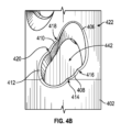
図4Aは、本開示の少なくとも一つの実施例に係わる、上腕骨用釘本体402内に形成された距貫通孔442の孔入口404の透視図である。距貫通孔142を参照して上述したように、距貫通孔442は角度可変ねじ軌道を定めることがある。図面では、距貫通孔442は3つの異なる距ねじ軌道を定める。
4A is a perspective view of a
一部の実施例では、孔入口404は4つの曲座面406、408、410、412を含むことがあり、各曲座面は3つのねじ軌道のうち1つに沿ってねじを受け入れるよう構成される。一部の実施例では、孔入口404は3つの交差する長円406、412、(曲座面408、410は組み合わさって3つの交差長円の1つを形成する)を含むことがある。少なくとも一つの実施例では、第1の曲座面406は、第2の曲座面408、410と第3の曲座面412に対して遠位で外側に位置することがある。少なくとも一つの実施例では、第3の曲座面412は、第1の曲座面406と第2の曲座面408、410に対して近位で内側に位置することがある。少なくとも一つの実施例では、曲座面406、408、410、412は係止端414、416、418、420で交わることがある。一部の実施例では、係止端414、416、418、420は、ねじを第1、第2、第3の距ねじ軌道のそれぞれに保持するよう構成されることがある。一部の実施例では、特に骨ねじが不良骨質に埋め込まれる場合に、ねじが上腕骨用釘を通って固定されることが重要である。
In some embodiments, the
一部の実施例では、曲座面406、408、410、412は、上腕骨用釘本体402の外径から内腔148にかけて傾斜又は先細りになっていることがある。少なくとも一つの実施例では、傾斜又は先細りによって、距ねじ軌道に望ましい角度を作る座面が提供され得る。少なくとも一つの実施例では、距貫通孔442が4つ以上の異なる距ねじ軌道を定められるように、距貫通孔442は5つ以上の曲座面406、408、410、412と5つ以上の係止端414、416、418、420とを含むことがある。
In some embodiments, the curved bearing surfaces 406, 408, 410, 412 may be tapered or tapered from the outer diameter of the
図4Bは、本開示の少なくとも一つの実施例に係わる、図4Aの距貫通孔402の孔出口422の透視図である。一部の実施例では、各距ねじ軌道が遠位から近位に延びるように、孔入口404は孔出口422より遠位に位置することがある。一部の実施例では、孔入口404は孔出口422に対して前方で外側に位置してもよい。少なくとも一つの実施例では、孔入口404は内側-外側軸線から50°前方に位置してもよく、孔出口422は内側-外側軸線からおよそ50°後方に位置してもよい。
FIG. 4B is a perspective view of the
一部の実施例では、孔出口422は4つの曲座面406、408、410、412を含むことがあり、各曲座面は3つのねじ軌道のうち1つに沿ってねじを受け入れるよう構成される。一部の実施例では、孔出口422は3つの交差長円406、412(曲座面408、410が組み合わさって3つの交差長円の1つを形成する)を含むことがある。少なくとも一つの実施例では、第1の曲座面406は、第2の曲座面408、410と第3の曲座面412に対して近位で内側に位置することがある。少なくとも一つの実施例では、第3の曲座面412は、第1の曲座面406と第2の曲座面408、410に対して遠位で外側に位置することがある。少なくとも一つの実施例では、曲座面406、408、410、412は、係止端414、416、418、420で交わることがある。一部の実施例では、係止端414、416、418、420は、ねじを第1、第2、第3の距ねじ軌道のそれぞれに保持するよう構成されることがある。一部の実施例では、特に骨ねじが不良骨質に埋め込まれる場合に、ねじが上腕骨用釘を通って固定されることが重要である。
In some embodiments, the
一部の実施例では、曲座面406、408、410、412は、上腕骨用釘本体402の外径から内腔148にかけて傾斜又は先細りになっていることがある。少なくとも一つの実施例では、傾斜又は先細りによって、距ねじ軌道に望ましい角度を作る座面が提供され得る。少なくとも一つの実施例では、距貫通孔442が4つ以上の異なる距ねじ軌道を定められるように、距貫通孔442は5つ以上の曲座面406、408、410、412と5つ以上の係止端414、416、418、420とを含むことがある。図例では、医師が一度に距貫通孔442を通して挿入するねじが一つだけとなるように、第1、第2、第3の距ねじ軌道が交差する。一部の実施例では、医師は、患者特定の解剖学的構造に基づいて、第1、第2、第3の距ねじ軌道から患者特定の軌道を選択することができる。少なくとも一つの実施例では、距貫通孔442は、近位-遠位軸線及び内側-外側軸線に対して異なる少なくとも3つの距ねじ軌道を定めることがある。
In some embodiments, the curved bearing surfaces 406, 408, 410, 412 may be tapered or tapered from the outer diameter of the
上述の「発明を実施するための形態」では、効率的に開示するために各種特徴が一つの例にまとめられていることが分かる。この開示方法は、記載された実施例が各請求項に明記されるよりも多くの特徴を要するという意図が反映されていると解釈してはならない。むしろ、以下の請求項に反映されるように、発明の主題は一つの開示例の特徴の全てよりも少ない特徴を持つものである。つまり、以下の特許請求の範囲は、明細書中の「発明を実施するための形態」に内包され、各請求項は別々の例として確立されている。 In the foregoing Detailed Description, it will be appreciated that various features are grouped together in a single example for purposes of efficient disclosure. This method of disclosure is not to be interpreted as reflecting an intention that the described embodiments require more features than are expressly recited in each claim. Rather, as the following claims reflect, inventive subject matter possesses fewer than all of the features of a single disclosed example. Thus, the following claims are hereby incorporated into the Detailed Description, with each claim standing on its own as a separate example.
なお、上記一般的な説明で述べた作用又は構成要素の全てが必要とされるものではなく、特定の作用又は装置の一部は必要とされないことがある。また、説明されたものに加えて、一以上の更なる作用が実施されたり、構成要素が含まれることがある。更に、作用が列挙される順番は、必ずしも作用が実施される順番ではない。また、発明の概念は特定の実施例を用いて説明された。しかしながら、当業者にとって当然のことながら、以下の特許請求の範囲に規定される本開示の範囲から逸脱することなく各種改変や変更が実施され得る。よって、本明細書と図面は限定的なものではなく、説明的なものであると解釈されるべきであり、そのような改変は本開示の範囲内に含まれることが意図される。 It should be noted that not all of the acts or components described in the general description above are required, and that certain acts or parts of the apparatus may not be required. Also, one or more additional acts may be performed or components may be included in addition to those described. Moreover, the order in which the acts are listed is not necessarily the order in which the acts are performed. Also, the inventive concepts have been described using specific examples. However, it should be understood by those skilled in the art that various modifications and changes may be made without departing from the scope of the present disclosure, as defined in the following claims. Thus, the present specification and drawings should be interpreted as illustrative rather than restrictive, and such modifications are intended to be included within the scope of the present disclosure.
利益、その他の利点、問題への解決策が特定の実施例に関連して上述された。しかしながら、これら利益、利点、問題への解決策、及び、今後発生する又はより強調される利益、利点、問題への解決策は、特許請求の範囲のいずれか又は全てに不可欠、必要、あるいは重要な特徴であると解釈されるべきではない。また、開示された主題は本明細書の開示事項から利益を享受する当業者にとっては明確な、異なるが同等の様式で改変されて実施され得るため、上記特定の実施例は説明のためにのみ開示されている。以下の特許請求の範囲に明記されない限り、本明細書に示された構成体又は設計の詳細にはいかなる制限も意図されない。したがって、当然のことながら、上述された特定の実施例は変更、改変されてもよく、そのような変形例の全ては開示された主題の範囲内にあると解釈される。また、本明細書中で求められる保護は以下の特許請求の範囲に規定される。
本発明は、以下の発明も含む。
第1の態様は、
釘本体の近位部から遠位部に延びる釘長手軸線を定める釘本体と、
前記釘本体内に形成され、孔出口に対して前方で近位に位置する孔入口を有し、前記釘本体を通る前方から後方への下降ねじ軌道を定める下降貫通孔とを備える上腕骨用釘である。
第2の態様は、
前記下降貫通孔は患者の小結節を標的にするために骨ねじを収容するよう構成される、第1の態様における上腕骨用釘である。
第3の態様は、
前記下降貫通孔が前記上腕骨用釘の前記近位部を通って延びる、第1の態様又は第2の態様における上腕骨用釘である。
第4の態様は、
前記釘本体を通り、前記下降ねじ軌道に交差する上昇ねじ軌道を定める上昇貫通孔を更に備える、第1の態様~第3の態様のいずれか一つにおける上腕骨用釘である。
第5の態様は、
前記上昇ねじ軌道と前記下降ねじ軌道のなす角度が近位-遠位方向に少なくとも40°であるよう構成される、第4の態様における上腕骨用釘である。
第6の態様は、
釘本体の近位部から前記釘本体の遠位部に延びる釘長手軸線を定める釘本体と、
前記釘本体内に形成され、前記釘長手軸線を横切って延びる第1のねじ軌道を定める第1の近位貫通孔と、
前記釘本体内に形成され、前記釘長手軸線を横切って延びる第2のねじ軌道を定める第2の近位貫通孔と、
前記釘本体内に形成され、前記釘長手軸線を横切って延びる第3のねじ軌道を定める第3の近位貫通孔と、
前記釘本体内に形成され、前方から後方及び近位から遠位に延びる下降ねじ軌道を定める下降貫通孔と、
前記釘本体内に形成され、前方から後方、外側から内側、及び遠位から近位に延びる距ねじ軌道を定める距貫通孔とを備える、上腕骨用釘である。
第7の態様は、
前記第1の近位貫通孔、前記第2の近位貫通孔、前記第3の近位貫通孔、前記下降貫通孔、及び前記距貫通孔は、前記釘本体の前記近位部を通って延びる、第6の態様における上腕骨用釘である。
第8の態様は、
前記第1の近位貫通孔は、前記第1のねじ軌道が内側-外側軸線に沿って外側から内側に延びることを定める、第6の態様又は第7の態様における上腕骨用釘である。
第9の態様は、
前記第2の近位貫通孔は、前記第2のねじ軌道が外側から内側及び後方から前方に延びることを定める、第6の態様~第8の態様のいずれか一つにおける上腕骨用釘である。
第10の態様は、
前記第3の近位貫通孔は、前記第3のねじ軌道が外側から内側及び前方から後方に延びることを定める、第6の態様~第9の態様のいずれか一つにおける上腕骨用釘である。
第11の態様は、
前記距貫通孔が角度可変距ねじ軌道を定める、第6の態様~第10の態様のいずれか一つにおける上腕骨用釘である。
第12の態様は、
前記釘本体内に形成され、前方から後方及び遠位から近位に延びる上昇ねじ軌道を定める上昇貫通孔を更に含む、第6の態様~第11の態様のいずれか一つにおける上腕骨用釘である。
第13の態様は、
上腕骨用釘本体の近位部から遠位部に延びる釘長手軸線を定める、上腕骨用釘本体と、
前記上腕骨用釘本体を通って延び、孔出口に対して前方及び外側に位置する孔入口を有する距貫通孔とを備え、
前記距貫通孔は遠位から近位に延びる少なくとも2つの異なる距ねじ軌道を定める、上腕骨用釘である。
第14の態様は、
前記孔入口は2つの交差長円を備える第13の態様における上腕骨用釘である。
第15の態様は、
前記少なくとも2つの異なる距ねじ軌道は近位-遠位方向及び内側-外側方向に異なる、第13の態様又は第14の態様における上腕骨用釘である。
第16の態様は、
前記孔入口は数字の8の字状の開口を備える、第13の態様~第15の態様のいずれか一つにおける上腕骨用釘である。
第17の態様は、
前記距貫通孔は少なくとも3つの異なる距ねじ軌道を定める、第13の態様~第16の態様のいずれか一つにおける上腕骨用釘である。
第18の態様は、
前記孔入口は3つの交差長円を備える、第13の態様~第17の態様のいずれか一つにおける上腕骨用釘である。
第19の態様は、
前記異なる距ねじ軌道のそれぞれは前記釘長手軸線から40°~60°の角度で延びる、第13の態様~第18の態様のいずれか一つにおける上腕骨用釘である。
第20の態様は、
前記孔入口は内側-外側軸線から前方におよそ50°に配置され、前記孔出口は内側-外側軸線から後方におよそ50°に配置される、第13の態様~第19の態様のいずれか一つにおける上腕骨用釘である。
Benefits, other advantages, and solutions to problems have been described above with respect to specific embodiments. However, these benefits, advantages, solutions to problems, and any benefits, advantages, solutions to problems that arise or are more clearly evident below, should not be construed as essential, necessary, or critical features of any or all of the claims. Moreover, the disclosed subject matter may be practiced in different but equivalent manners apparent to those skilled in the art having the benefit of the disclosure herein. No limitations are intended to the details of construction or design shown herein, unless expressly set forth in the following claims. It is therefore to be understood that the particular embodiments described above may be altered or modified, and all such variations are intended to be within the scope of the disclosed subject matter. Moreover, the protection sought herein is defined in the following claims.
The present invention also includes the following inventions.
The first aspect is
a nail body defining a nail longitudinal axis extending from a proximal portion to a distal portion of the nail body;
a descending through hole formed within the nail body, the through hole having a hole entry located anteriorly and proximally relative to the hole exit, the descending through hole defining an anterior-to-posterior descending thread trajectory through the nail body.
The second aspect is
The humeral nail in a first aspect, wherein the descending through-bore is configured to receive a bone screw for targeting the patient's tuberosity.
The third aspect is
The humeral nail of the first or second aspect, wherein the descending throughbore extends through the proximal portion of the humeral nail.
The fourth aspect is
The humerus nail of any one of the first to third aspects, further comprising an elevation throughbore passing through the nail body and defining an elevation screw trajectory that intersects with the descending screw trajectory.
The fifth aspect is
The humeral nail of a fourth aspect, wherein the angle between the ascending thread trajectory and the descending thread trajectory is at least 40° in a proximal-distal direction.
The sixth aspect is
a nail body defining a nail longitudinal axis extending from a proximal portion of the nail body to a distal portion of the nail body;
a first proximal throughbore formed within the nail body and defining a first thread trajectory extending transverse to the nail longitudinal axis;
a second proximal throughbore formed within the nail body and defining a second thread track extending transverse to the nail longitudinal axis;
a third proximal throughbore formed within the nail body and defining a third thread track extending transverse to the nail longitudinal axis;
a descending throughbore formed within the nail body and defining a descending thread trajectory extending anteriorly to posteriorly and proximally to distally;
and a calcaneal through hole formed within the nail body that defines a calcaneal screw trajectory extending anterior to posterior, lateral to medial, and distal to proximal.
The seventh aspect is
A sixth aspect of the humerus nail, wherein the first proximal through hole, the second proximal through hole, the third proximal through hole, the descending through hole, and the anterior through hole extend through the proximal portion of the nail body.
The eighth aspect is
The first proximal throughbore is the humeral nail of the sixth or seventh aspect, wherein the first thread trajectory defines a lateral-to-medial extension along a medial-lateral axis.
The ninth aspect is
The humeral nail according to any one of the sixth to eighth aspects, wherein the second proximal through hole defines the second screw trajectory extending from lateral to medial and posterior to anterior.
A tenth aspect is
The humeral nail according to any one of the sixth to ninth aspects, wherein the third proximal through hole defines the third thread trajectory extending from lateral to medial and anterior to posterior.
An eleventh aspect is
The humerus nail according to any one of the sixth to tenth aspects, wherein the calcaneal through hole defines an angle variable calcaneal screw trajectory.
A twelfth aspect is
The humerus nail of any one of the sixth to eleventh aspects further includes an elevation through hole formed within the nail body and defining an elevation screw trajectory extending from anterior to posterior and distal to proximal.
A thirteenth aspect is
a humeral nail body defining a nail longitudinal axis extending from a proximal portion to a distal portion of the humeral nail body;
a calcaneal through hole extending through the humeral nail body and having a hole entrance located anteriorly and laterally relative to the hole exit;
The calcaneal through hole is a humeral nail that defines at least two different calcaneal screw trajectories extending distally to proximally.
A fourteenth aspect is
The humerus nail in a thirteenth aspect, wherein the hole entry comprises two intersecting ellipses.
A fifteenth aspect is
The humeral nail according to the thirteenth or fourteenth aspect, wherein the at least two different talar screw trajectories differ in the proximal-distal direction and the medial-lateral direction.
A sixteenth aspect is
The humerus nail according to any one of the thirteenth to fifteenth aspects, wherein the hole entrance has a figure eight shaped opening.
A seventeenth aspect is
The humerus nail according to any one of the thirteenth to sixteenth aspects, wherein the calcaneal through hole defines at least three different calcaneal screw trajectories.
The eighteenth aspect is
The humerus nail according to any one of the thirteenth to seventeenth aspects, wherein the hole entrance comprises three intersecting ellipses.
A nineteenth aspect is
The humeral nail according to any one of the thirteenth to eighteenth aspects, wherein each of the different calcaneal screw tracks extends at an angle of between 40° and 60° from the nail longitudinal axis.
A twentieth aspect is
A humerus nail in any one of the thirteenth to nineteenth aspects, wherein the hole inlet is positioned approximately 50° anterior from the medial-lateral axis and the hole outlet is positioned approximately 50° posterior from the medial-lateral axis.
Claims (10)
前記釘本体内に形成され、前記釘長手軸線を横切って延びる第1のねじ軌道を定める第1の近位貫通孔と、
前記釘本体内に形成され、前記釘長手軸線を横切って延びる第2のねじ軌道を定める第2の近位貫通孔と、
前記釘本体内に形成され、前記釘長手軸線を横切って延びる第3のねじ軌道を定める第3の近位貫通孔と、
前記釘本体内に形成され、患者の上腕が基本肢位にあるときに、患者の上腕骨の前方に対応する前方及び患者の上腕骨の近位に対応する近位から患者の上腕骨の後方に対応する後方及び患者の上腕骨の遠位に対応する遠位に延びる、患者の小結節を標的にする下降ねじ軌道を定める下降貫通孔と、
前記釘本体内に形成されておりかつ患者の上腕骨の距領域を標的にするように構成された距ねじ軌道を定める上腕骨用距貫通孔であって、前記距ねじ軌道が上腕骨頭の内側かつ後部の象限にねじを位置決めするように構成されるように、患者の上腕が基本肢位にあるときに、前記距ねじ軌道が患者の上腕骨の前方に対応する前方から患者の上腕骨後方に対応する後方に、患者の上腕骨の外側に対応する外側から患者の上腕骨の内側に対応する内側に、及び患者の上腕骨の遠位に対応する遠位から患者の上腕骨の近位に対応する近位に延びる、上腕骨用距貫通孔とを備え、
前記第1の近位貫通孔、前記第2の近位貫通孔、前記第3の近位貫通孔、前記下降貫通孔、及び前記上腕骨用距貫通孔は、前記釘本体の前記近位部を通って延びる、上腕骨用釘。 a nail body defining a nail longitudinal axis extending from a proximal portion of the nail body to a distal portion of the nail body;
a first proximal throughbore formed within the nail body and defining a first thread trajectory extending transverse to the nail longitudinal axis;
a second proximal throughbore formed within the nail body and defining a second thread track extending transverse to the nail longitudinal axis;
a third proximal throughbore formed within the nail body and defining a third thread track extending transverse to the nail longitudinal axis;
a descending through hole formed within the nail body and defining a descending screw trajectory for targeting the patient's tuberosity, the descending through hole extending from an anterior corresponding to an anterior of the patient's humerus and a proximal corresponding to a proximal portion of the patient's humerus to a posterior corresponding to a posterior portion of the patient's humerus and a distal corresponding to a distal portion of the patient's humerus when the patient's upper arm is in a home position;
a humeral calcaneal through hole formed within the nail body and defining a calcaneal screw trajectory configured to target a calcaneal region of the patient's humerus, the calcaneal screw trajectory extending from anterior to posterior to posterior of the patient's humerus, from lateral to medial to medial, and from distal to proximal to proximal of the patient's humerus when the patient's upper arm is in a home position such that the calcaneal screw trajectory is configured to position a screw in the medial and posterior quadrants of the humeral head;
The humeral nail, wherein the first proximal through-hole, the second proximal through-hole, the third proximal through-hole, the descending through-hole, and the humeral calcar through-hole extend through the proximal portion of the nail body.
前記釘長手軸線を横切って前記上腕骨用釘本体を通って延び、孔入口及び孔出口を有する、上腕骨用距貫通孔であって、前記孔入口が前記孔出口に対して患者の上腕が基本肢位にあるときに患者の上腕骨の前方に対応する前方及び患者の上腕骨の外側に対応する外側に位置する、上腕骨用距貫通孔とを備え、
上腕骨用距ねじ軌道が上腕骨頭の内側かつ後部の象限にねじを位置決めするように構成されるように、前記上腕骨用距貫通孔は、患者の上腕が基本肢位にあるときに、患者の上腕骨の前方に対応する前方から患者の上腕骨の後方に対応する後方かつ患者の上腕骨の遠位に対応する遠位から患者の上腕骨の近位に対応する近位に延びる、上腕骨の距領域を標的にする少なくとも4つの異なる上腕骨用距ねじ軌道を定め、
骨ねじは選択された前記上腕骨用距ねじ軌道に沿って前進する、上腕骨用釘。 a humeral nail body defining a nail longitudinal axis extending from a proximal portion to a distal portion of the humeral nail body and adapted to be implanted into a patient's humerus;
a humerus calcaneal through-hole extending through the humerus nail body transverse to the nail longitudinal axis and having an inlet and an outlet, the inlet being positioned anteriorly to the inlet and laterally to the lateral side of the patient's humerus when the patient's upper arm is in a home position;
the humeral calcaneal through holes define at least four different humeral calcaneal screw trajectories for targeting a calcaneal region of the humerus, the humeral calcaneal screw trajectories extending from anterior corresponding to an anterior of the patient's humerus to posterior corresponding to a posterior of the patient's humerus and from distal corresponding to a distal portion of the patient's humerus to proximal corresponding to a proximal portion of the patient's humerus when the patient's upper arm is in a home position, such that the humeral calcaneal screw trajectories are configured to position screws in the medial and posterior quadrants of the humeral head;
A humeral nail, wherein the bone screw advances along the selected humeral talus screw trajectory.
Priority Applications (1)
| Application Number | Priority Date | Filing Date | Title |
|---|---|---|---|
| JP2022017290A JP2022080896A (en) | 2015-04-24 | 2022-02-07 | Humerus nail |
Applications Claiming Priority (3)
| Application Number | Priority Date | Filing Date | Title |
|---|---|---|---|
| US201562152339P | 2015-04-24 | 2015-04-24 | |
| US62/152,339 | 2015-04-24 | ||
| PCT/US2016/028998 WO2016172594A1 (en) | 2015-04-24 | 2016-04-22 | Humeral nail |
Related Child Applications (1)
| Application Number | Title | Priority Date | Filing Date |
|---|---|---|---|
| JP2022017290A Division JP2022080896A (en) | 2015-04-24 | 2022-02-07 | Humerus nail |
Publications (2)
| Publication Number | Publication Date |
|---|---|
| JP2018514359A JP2018514359A (en) | 2018-06-07 |
| JP7488024B2 true JP7488024B2 (en) | 2024-05-21 |
Family
ID=55910418
Family Applications (2)
| Application Number | Title | Priority Date | Filing Date |
|---|---|---|---|
| JP2018506806A Active JP7488024B2 (en) | 2015-04-24 | 2016-04-22 | Humerus nail |
| JP2022017290A Pending JP2022080896A (en) | 2015-04-24 | 2022-02-07 | Humerus nail |
Family Applications After (1)
| Application Number | Title | Priority Date | Filing Date |
|---|---|---|---|
| JP2022017290A Pending JP2022080896A (en) | 2015-04-24 | 2022-02-07 | Humerus nail |
Country Status (7)
| Country | Link |
|---|---|
| US (1) | US12011198B2 (en) |
| EP (2) | EP3294167B1 (en) |
| JP (2) | JP7488024B2 (en) |
| CN (1) | CN108124424B (en) |
| AU (1) | AU2016252884B2 (en) |
| CA (1) | CA2983664C (en) |
| WO (1) | WO2016172594A1 (en) |
Families Citing this family (15)
| Publication number | Priority date | Publication date | Assignee | Title |
|---|---|---|---|---|
| EP2604225A1 (en) | 2011-10-31 | 2013-06-19 | Tornier Orthopedics Ireland Ltd. | Modular reverse shoulder prosthesis |
| EP4603062A3 (en) | 2012-10-29 | 2025-10-22 | Stryker European Operations Limited | System for a modular reverse shoulder prosthesis |
| FR3029769A1 (en) | 2014-12-10 | 2016-06-17 | Tornier Sa | KIT FOR A PROSTHESIS OF SHOULDER |
| WO2016172594A1 (en) | 2015-04-24 | 2016-10-27 | Scott Van Dyke | Humeral nail |
| AU2017253113B2 (en) | 2016-04-19 | 2021-10-07 | Stryker European Operations Limited | Pre-operatively planned humeral implant and planning method |
| WO2018069554A1 (en) * | 2016-10-10 | 2018-04-19 | Ferrero Manzanal Francisco | Intramedullary nailing system of variable angle to treat femur fractures |
| US10610270B2 (en) | 2018-01-15 | 2020-04-07 | Glw, Inc. | Hybrid intramedullary rods |
| EP3520738B1 (en) | 2018-01-31 | 2021-01-06 | Tornier | Prosthesis for a fractured long bone |
| USD938590S1 (en) | 2019-10-01 | 2021-12-14 | Howmedica Osteonics Corp. | Humeral implant |
| WO2021176274A1 (en) | 2020-03-06 | 2021-09-10 | Stryker European Operations Limited | Set screw for femoral nail |
| WO2021176272A1 (en) | 2020-03-06 | 2021-09-10 | Stryker European Operations Limited | Set screw for femoral nail |
| WO2021223755A1 (en) * | 2020-05-08 | 2021-11-11 | Lifespans Limited | Bone fixation system and elements thereof |
| WO2021240242A1 (en) | 2020-05-29 | 2021-12-02 | Stryker European Operations Limited | Funnel hole for intramedullary nail |
| AU2022239629B2 (en) * | 2021-03-17 | 2024-11-14 | Howmedica Osteonics Corp. | Humeral implant and systems and methods for implanting the same |
| WO2022251501A1 (en) * | 2021-05-28 | 2022-12-01 | Acumed Llc | Bone fixation systems and nail having compressive threading |
Citations (5)
| Publication number | Priority date | Publication date | Assignee | Title |
|---|---|---|---|---|
| JP2002253566A (en) | 2001-03-01 | 2002-09-10 | Mizuho Co Ltd | Intramedullary nail |
| US20060122600A1 (en) | 1999-06-10 | 2006-06-08 | Orthodyne, Inc. | Femoral intramedullary rod system |
| JP2007125388A (en) | 2005-10-31 | 2007-05-24 | Depuy Products Inc | Multipurpose nail having slanting opening |
| JP2011519658A (en) | 2008-05-07 | 2011-07-14 | トゥルニエ | Humeral nail |
| JP2014531232A (en) | 2011-09-16 | 2014-11-27 | ストライカー トラウマ ゲーエムベーハー | Multi-axis locking hole configuration |
Family Cites Families (21)
| Publication number | Priority date | Publication date | Assignee | Title |
|---|---|---|---|---|
| US5480402A (en) * | 1993-08-05 | 1996-01-02 | Kim; Andrew C. | Shoulder compression interlocking system |
| US5472444A (en) * | 1994-05-13 | 1995-12-05 | Acumed, Inc. | Humeral nail for fixation of proximal humeral fractures |
| US5549610A (en) * | 1994-10-31 | 1996-08-27 | Smith & Nephew Richards Inc. | Femoral intramedullary nail |
| US6296645B1 (en) * | 1999-04-09 | 2001-10-02 | Depuy Orthopaedics, Inc. | Intramedullary nail with non-metal spacers |
| US7914532B2 (en) * | 2005-10-21 | 2011-03-29 | Acumed Llc | Orthopedic rod with locking aperture |
| DE20213166U1 (en) | 2002-08-28 | 2004-01-08 | Stryker Trauma Gmbh | humeral |
| ES2379877T3 (en) | 2003-12-01 | 2012-05-04 | Smith & Nephew, Inc. | Humeral nail with an insert to fix a screw |
| FR2881340B1 (en) | 2005-02-01 | 2008-01-11 | Tornier Sas | HUMERAL NUTS |
| US7232442B2 (en) | 2005-02-22 | 2007-06-19 | Advanced Orthopaedic Solutions | Humeral nail |
| US8961516B2 (en) * | 2005-05-18 | 2015-02-24 | Sonoma Orthopedic Products, Inc. | Straight intramedullary fracture fixation devices and methods |
| US20070123873A1 (en) | 2005-10-31 | 2007-05-31 | Czartoski Timothy J | Intramedullary nail with oblique openings |
| US20070233102A1 (en) | 2006-03-31 | 2007-10-04 | Metzinger Anthony J | Variable angle fixture, kit and method of presetting a nail assembly |
| US9308031B2 (en) * | 2007-01-26 | 2016-04-12 | Biomet Manufacturing, Llc | Lockable intramedullary fixation device |
| EP2207503B1 (en) | 2007-09-27 | 2014-04-23 | Synthes GmbH | Nail-plate combination |
| US20090157078A1 (en) * | 2007-12-17 | 2009-06-18 | Mikol Edward J | Apparatus and Methods of Repairing Bone Defects |
| JP5801297B2 (en) | 2009-06-30 | 2015-10-28 | スミス アンド ネフュー インコーポレーテッド | Orthopedic graft and fastener assembly |
| US8771271B2 (en) * | 2011-02-14 | 2014-07-08 | DePuy Synthes Products, LLC | Intramedullary nail having self-retaining compression slot |
| US8876822B2 (en) * | 2012-04-13 | 2014-11-04 | Orthopedic Designs North American, Inc. | Intramedullary nail system with tang fixation after lock screw placement |
| CN204033457U (en) | 2014-05-12 | 2014-12-24 | 万承兴 | A kind of modified form femoral intertrochanteric fixture |
| CN204072294U (en) | 2014-08-07 | 2015-01-07 | 上海市第一人民医院 | A kind of intramedullary pin for implanting humerus medullary cavity |
| WO2016172594A1 (en) | 2015-04-24 | 2016-10-27 | Scott Van Dyke | Humeral nail |
-
2016
- 2016-04-22 WO PCT/US2016/028998 patent/WO2016172594A1/en not_active Ceased
- 2016-04-22 EP EP16720299.3A patent/EP3294167B1/en active Active
- 2016-04-22 AU AU2016252884A patent/AU2016252884B2/en active Active
- 2016-04-22 CN CN201680032929.XA patent/CN108124424B/en active Active
- 2016-04-22 CA CA2983664A patent/CA2983664C/en active Active
- 2016-04-22 EP EP21174513.8A patent/EP3884892B1/en active Active
- 2016-04-22 US US15/136,700 patent/US12011198B2/en active Active
- 2016-04-22 JP JP2018506806A patent/JP7488024B2/en active Active
-
2022
- 2022-02-07 JP JP2022017290A patent/JP2022080896A/en active Pending
Patent Citations (5)
| Publication number | Priority date | Publication date | Assignee | Title |
|---|---|---|---|---|
| US20060122600A1 (en) | 1999-06-10 | 2006-06-08 | Orthodyne, Inc. | Femoral intramedullary rod system |
| JP2002253566A (en) | 2001-03-01 | 2002-09-10 | Mizuho Co Ltd | Intramedullary nail |
| JP2007125388A (en) | 2005-10-31 | 2007-05-24 | Depuy Products Inc | Multipurpose nail having slanting opening |
| JP2011519658A (en) | 2008-05-07 | 2011-07-14 | トゥルニエ | Humeral nail |
| JP2014531232A (en) | 2011-09-16 | 2014-11-27 | ストライカー トラウマ ゲーエムベーハー | Multi-axis locking hole configuration |
Non-Patent Citations (1)
| Title |
|---|
| 寺田忠司、髄内釘(1)、MB Orthopaedics、日本、2014,発行、第27巻 第8号、43-55ページ |
Also Published As
| Publication number | Publication date |
|---|---|
| US12011198B2 (en) | 2024-06-18 |
| EP3884892B1 (en) | 2023-09-27 |
| WO2016172594A1 (en) | 2016-10-27 |
| AU2016252884A1 (en) | 2017-11-30 |
| JP2022080896A (en) | 2022-05-30 |
| CN108124424A (en) | 2018-06-05 |
| CA2983664C (en) | 2023-09-19 |
| AU2016252884B2 (en) | 2021-05-06 |
| EP3884892A3 (en) | 2021-12-08 |
| EP3294167B1 (en) | 2021-05-19 |
| CA2983664A1 (en) | 2016-10-27 |
| JP2018514359A (en) | 2018-06-07 |
| US20160310176A1 (en) | 2016-10-27 |
| EP3884892A2 (en) | 2021-09-29 |
| CN108124424B (en) | 2021-06-22 |
| EP3294167A1 (en) | 2018-03-21 |
Similar Documents
| Publication | Publication Date | Title |
|---|---|---|
| JP7488024B2 (en) | Humerus nail | |
| US11779382B2 (en) | Alignment guide apparatus, methods and systems | |
| US20240032977A1 (en) | Bone fixation system, assembly, implants, devices, alignment guides, and methods of use | |
| JP5270375B2 (en) | Tibial plateau leveling rib plate | |
| KR101711003B1 (en) | plating concept for distal radial fractures | |
| JP5073668B2 (en) | Bone fixation assembly and bushes and screws used therewith | |
| US9545273B2 (en) | Polyaxial locking hole arrangement | |
| AU2015284584A1 (en) | Locking first metacarpal plate | |
| WO2014165158A1 (en) | Hammertoe implant with asymmetrical head | |
| EP3820382B1 (en) | Systems comprising alignment guides and implants | |
| US20160135857A1 (en) | Curved tibiotalar fusion nail and method of use | |
| US10932828B2 (en) | Bone nail | |
| EP3160371B1 (en) | Phalangeal head plate | |
| CN114711942A (en) | Intramedullary nail with blocking bolt and aiming system thereof | |
| JP6270933B2 (en) | Treatment instrument and fixation plate for femoral fracture |
Legal Events
| Date | Code | Title | Description |
|---|---|---|---|
| A521 | Request for written amendment filed |
Free format text: JAPANESE INTERMEDIATE CODE: A523 Effective date: 20171115 Free format text: JAPANESE INTERMEDIATE CODE: A523 Effective date: 20171206 |
|
| A621 | Written request for application examination |
Free format text: JAPANESE INTERMEDIATE CODE: A621 Effective date: 20190419 |
|
| A977 | Report on retrieval |
Free format text: JAPANESE INTERMEDIATE CODE: A971007 Effective date: 20200214 |
|
| A131 | Notification of reasons for refusal |
Free format text: JAPANESE INTERMEDIATE CODE: A131 Effective date: 20200225 |
|
| A601 | Written request for extension of time |
Free format text: JAPANESE INTERMEDIATE CODE: A601 Effective date: 20200522 |
|
| A521 | Request for written amendment filed |
Free format text: JAPANESE INTERMEDIATE CODE: A523 Effective date: 20200825 |
|
| A131 | Notification of reasons for refusal |
Free format text: JAPANESE INTERMEDIATE CODE: A131 Effective date: 20200915 |
|
| A601 | Written request for extension of time |
Free format text: JAPANESE INTERMEDIATE CODE: A601 Effective date: 20201214 |
|
| A521 | Request for written amendment filed |
Free format text: JAPANESE INTERMEDIATE CODE: A523 Effective date: 20210121 |
|
| A131 | Notification of reasons for refusal |
Free format text: JAPANESE INTERMEDIATE CODE: A131 Effective date: 20210302 |
|
| A601 | Written request for extension of time |
Free format text: JAPANESE INTERMEDIATE CODE: A601 Effective date: 20210531 |
|
| A521 | Request for written amendment filed |
Free format text: JAPANESE INTERMEDIATE CODE: A523 Effective date: 20210730 |
|
| A02 | Decision of refusal |
Free format text: JAPANESE INTERMEDIATE CODE: A02 Effective date: 20211005 |
|
| A521 | Request for written amendment filed |
Free format text: JAPANESE INTERMEDIATE CODE: A523 Effective date: 20220207 |
|
| A711 | Notification of change in applicant |
Free format text: JAPANESE INTERMEDIATE CODE: A711 Effective date: 20220207 |
|
| C60 | Trial request (containing other claim documents, opposition documents) |
Free format text: JAPANESE INTERMEDIATE CODE: C60 Effective date: 20220207 |
|
| C12 | Written invitation by the commissioner to file intermediate amendments |
Free format text: JAPANESE INTERMEDIATE CODE: C12 Effective date: 20220308 |
|
| A911 | Transfer to examiner for re-examination before appeal (zenchi) |
Free format text: JAPANESE INTERMEDIATE CODE: A911 Effective date: 20220517 |
|
| C21 | Notice of transfer of a case for reconsideration by examiners before appeal proceedings |
Free format text: JAPANESE INTERMEDIATE CODE: C21 Effective date: 20220524 |
|
| A912 | Re-examination (zenchi) completed and case transferred to appeal board |
Free format text: JAPANESE INTERMEDIATE CODE: A912 Effective date: 20220902 |
|
| C211 | Notice of termination of reconsideration by examiners before appeal proceedings |
Free format text: JAPANESE INTERMEDIATE CODE: C211 Effective date: 20220906 |
|
| C22 | Notice of designation (change) of administrative judge |
Free format text: JAPANESE INTERMEDIATE CODE: C22 Effective date: 20221004 |
|
| C13 | Notice of reasons for refusal |
Free format text: JAPANESE INTERMEDIATE CODE: C13 Effective date: 20221115 |
|
| C28A | Non-patent document cited |
Free format text: JAPANESE INTERMEDIATE CODE: C2838 Effective date: 20221115 |
|
| C27B | Notice of submission of publications, etc. [third party observations] |
Free format text: JAPANESE INTERMEDIATE CODE: C2714 Effective date: 20221122 |
|
| A521 | Request for written amendment filed |
Free format text: JAPANESE INTERMEDIATE CODE: A523 Effective date: 20230215 |
|
| C13 | Notice of reasons for refusal |
Free format text: JAPANESE INTERMEDIATE CODE: C13 Effective date: 20230411 |
|
| C22 | Notice of designation (change) of administrative judge |
Free format text: JAPANESE INTERMEDIATE CODE: C22 Effective date: 20230411 |
|
| C27B | Notice of submission of publications, etc. [third party observations] |
Free format text: JAPANESE INTERMEDIATE CODE: C2714 Effective date: 20230411 |
|
| A521 | Request for written amendment filed |
Free format text: JAPANESE INTERMEDIATE CODE: A523 Effective date: 20230711 |
|
| A521 | Request for written amendment filed |
Free format text: JAPANESE INTERMEDIATE CODE: A523 Effective date: 20240130 |
|
| A61 | First payment of annual fees (during grant procedure) |
Free format text: JAPANESE INTERMEDIATE CODE: A61 Effective date: 20240509 |
|
| R150 | Certificate of patent or registration of utility model |
Ref document number: 7488024 Country of ref document: JP Free format text: JAPANESE INTERMEDIATE CODE: R150 |