JP7513751B2 - Battery housing, battery, power consumption device, battery manufacturing method and device - Google Patents
Battery housing, battery, power consumption device, battery manufacturing method and device Download PDFInfo
- Publication number
- JP7513751B2 JP7513751B2 JP2022567658A JP2022567658A JP7513751B2 JP 7513751 B2 JP7513751 B2 JP 7513751B2 JP 2022567658 A JP2022567658 A JP 2022567658A JP 2022567658 A JP2022567658 A JP 2022567658A JP 7513751 B2 JP7513751 B2 JP 7513751B2
- Authority
- JP
- Japan
- Prior art keywords
- housing
- liquid
- battery
- wall
- gravity
- Prior art date
- Legal status (The legal status is an assumption and is not a legal conclusion. Google has not performed a legal analysis and makes no representation as to the accuracy of the status listed.)
- Active
Links
Images


Classifications
-
- H—ELECTRICITY
- H01—ELECTRIC ELEMENTS
- H01M—PROCESSES OR MEANS, e.g. BATTERIES, FOR THE DIRECT CONVERSION OF CHEMICAL ENERGY INTO ELECTRICAL ENERGY
- H01M50/00—Constructional details or processes of manufacture of the non-active parts of electrochemical cells other than fuel cells, e.g. hybrid cells
- H01M50/60—Arrangements or processes for filling or topping-up with liquids; Arrangements or processes for draining liquids from casings
- H01M50/691—Arrangements or processes for draining liquids from casings; Cleaning battery or cell casings
-
- A—HUMAN NECESSITIES
- A62—LIFE-SAVING; FIRE-FIGHTING
- A62C—FIRE-FIGHTING
- A62C3/00—Fire prevention, containment or extinguishing specially adapted for particular objects or places
- A62C3/16—Fire prevention, containment or extinguishing specially adapted for particular objects or places in electrical installations, e.g. cableways
-
- H—ELECTRICITY
- H01—ELECTRIC ELEMENTS
- H01M—PROCESSES OR MEANS, e.g. BATTERIES, FOR THE DIRECT CONVERSION OF CHEMICAL ENERGY INTO ELECTRICAL ENERGY
- H01M10/00—Secondary cells; Manufacture thereof
- H01M10/04—Construction or manufacture in general
- H01M10/0404—Machines for assembling batteries
-
- H—ELECTRICITY
- H01—ELECTRIC ELEMENTS
- H01M—PROCESSES OR MEANS, e.g. BATTERIES, FOR THE DIRECT CONVERSION OF CHEMICAL ENERGY INTO ELECTRICAL ENERGY
- H01M10/00—Secondary cells; Manufacture thereof
- H01M10/42—Methods or arrangements for servicing or maintenance of secondary cells or secondary half-cells
-
- H—ELECTRICITY
- H01—ELECTRIC ELEMENTS
- H01M—PROCESSES OR MEANS, e.g. BATTERIES, FOR THE DIRECT CONVERSION OF CHEMICAL ENERGY INTO ELECTRICAL ENERGY
- H01M10/00—Secondary cells; Manufacture thereof
- H01M10/60—Heating or cooling; Temperature control
-
- H—ELECTRICITY
- H01—ELECTRIC ELEMENTS
- H01M—PROCESSES OR MEANS, e.g. BATTERIES, FOR THE DIRECT CONVERSION OF CHEMICAL ENERGY INTO ELECTRICAL ENERGY
- H01M10/00—Secondary cells; Manufacture thereof
- H01M10/60—Heating or cooling; Temperature control
- H01M10/61—Types of temperature control
- H01M10/613—Cooling or keeping cold
-
- H—ELECTRICITY
- H01—ELECTRIC ELEMENTS
- H01M—PROCESSES OR MEANS, e.g. BATTERIES, FOR THE DIRECT CONVERSION OF CHEMICAL ENERGY INTO ELECTRICAL ENERGY
- H01M10/00—Secondary cells; Manufacture thereof
- H01M10/60—Heating or cooling; Temperature control
- H01M10/62—Heating or cooling; Temperature control specially adapted for specific applications
- H01M10/625—Vehicles
-
- H—ELECTRICITY
- H01—ELECTRIC ELEMENTS
- H01M—PROCESSES OR MEANS, e.g. BATTERIES, FOR THE DIRECT CONVERSION OF CHEMICAL ENERGY INTO ELECTRICAL ENERGY
- H01M50/00—Constructional details or processes of manufacture of the non-active parts of electrochemical cells other than fuel cells, e.g. hybrid cells
- H01M50/20—Mountings; Secondary casings or frames; Racks, modules or packs; Suspension devices; Shock absorbers; Transport or carrying devices; Holders
- H01M50/202—Casings or frames around the primary casing of a single cell or a single battery
-
- H—ELECTRICITY
- H01—ELECTRIC ELEMENTS
- H01M—PROCESSES OR MEANS, e.g. BATTERIES, FOR THE DIRECT CONVERSION OF CHEMICAL ENERGY INTO ELECTRICAL ENERGY
- H01M50/00—Constructional details or processes of manufacture of the non-active parts of electrochemical cells other than fuel cells, e.g. hybrid cells
- H01M50/20—Mountings; Secondary casings or frames; Racks, modules or packs; Suspension devices; Shock absorbers; Transport or carrying devices; Holders
- H01M50/204—Racks, modules or packs for multiple batteries or multiple cells
-
- H—ELECTRICITY
- H01—ELECTRIC ELEMENTS
- H01M—PROCESSES OR MEANS, e.g. BATTERIES, FOR THE DIRECT CONVERSION OF CHEMICAL ENERGY INTO ELECTRICAL ENERGY
- H01M50/00—Constructional details or processes of manufacture of the non-active parts of electrochemical cells other than fuel cells, e.g. hybrid cells
- H01M50/20—Mountings; Secondary casings or frames; Racks, modules or packs; Suspension devices; Shock absorbers; Transport or carrying devices; Holders
- H01M50/233—Mountings; Secondary casings or frames; Racks, modules or packs; Suspension devices; Shock absorbers; Transport or carrying devices; Holders characterised by physical properties of casings or racks, e.g. dimensions
- H01M50/24—Mountings; Secondary casings or frames; Racks, modules or packs; Suspension devices; Shock absorbers; Transport or carrying devices; Holders characterised by physical properties of casings or racks, e.g. dimensions adapted for protecting batteries from their environment, e.g. from corrosion
-
- H—ELECTRICITY
- H01—ELECTRIC ELEMENTS
- H01M—PROCESSES OR MEANS, e.g. BATTERIES, FOR THE DIRECT CONVERSION OF CHEMICAL ENERGY INTO ELECTRICAL ENERGY
- H01M50/00—Constructional details or processes of manufacture of the non-active parts of electrochemical cells other than fuel cells, e.g. hybrid cells
- H01M50/20—Mountings; Secondary casings or frames; Racks, modules or packs; Suspension devices; Shock absorbers; Transport or carrying devices; Holders
- H01M50/249—Mountings; Secondary casings or frames; Racks, modules or packs; Suspension devices; Shock absorbers; Transport or carrying devices; Holders specially adapted for aircraft or vehicles, e.g. cars or trains
-
- H—ELECTRICITY
- H01—ELECTRIC ELEMENTS
- H01M—PROCESSES OR MEANS, e.g. BATTERIES, FOR THE DIRECT CONVERSION OF CHEMICAL ENERGY INTO ELECTRICAL ENERGY
- H01M50/00—Constructional details or processes of manufacture of the non-active parts of electrochemical cells other than fuel cells, e.g. hybrid cells
- H01M50/20—Mountings; Secondary casings or frames; Racks, modules or packs; Suspension devices; Shock absorbers; Transport or carrying devices; Holders
- H01M50/271—Lids or covers for the racks or secondary casings
-
- H—ELECTRICITY
- H01—ELECTRIC ELEMENTS
- H01M—PROCESSES OR MEANS, e.g. BATTERIES, FOR THE DIRECT CONVERSION OF CHEMICAL ENERGY INTO ELECTRICAL ENERGY
- H01M50/00—Constructional details or processes of manufacture of the non-active parts of electrochemical cells other than fuel cells, e.g. hybrid cells
- H01M50/30—Arrangements for facilitating escape of gases
- H01M50/394—Gas-pervious parts or elements
-
- H—ELECTRICITY
- H01—ELECTRIC ELEMENTS
- H01M—PROCESSES OR MEANS, e.g. BATTERIES, FOR THE DIRECT CONVERSION OF CHEMICAL ENERGY INTO ELECTRICAL ENERGY
- H01M50/00—Constructional details or processes of manufacture of the non-active parts of electrochemical cells other than fuel cells, e.g. hybrid cells
- H01M50/50—Current conducting connections for cells or batteries
- H01M50/572—Means for preventing undesired use or discharge
- H01M50/584—Means for preventing undesired use or discharge for preventing incorrect connections inside or outside the batteries
-
- H—ELECTRICITY
- H01—ELECTRIC ELEMENTS
- H01M—PROCESSES OR MEANS, e.g. BATTERIES, FOR THE DIRECT CONVERSION OF CHEMICAL ENERGY INTO ELECTRICAL ENERGY
- H01M50/00—Constructional details or processes of manufacture of the non-active parts of electrochemical cells other than fuel cells, e.g. hybrid cells
- H01M50/60—Arrangements or processes for filling or topping-up with liquids; Arrangements or processes for draining liquids from casings
- H01M50/609—Arrangements or processes for filling with liquid, e.g. electrolytes
- H01M50/627—Filling ports
-
- H—ELECTRICITY
- H01—ELECTRIC ELEMENTS
- H01M—PROCESSES OR MEANS, e.g. BATTERIES, FOR THE DIRECT CONVERSION OF CHEMICAL ENERGY INTO ELECTRICAL ENERGY
- H01M50/00—Constructional details or processes of manufacture of the non-active parts of electrochemical cells other than fuel cells, e.g. hybrid cells
- H01M50/60—Arrangements or processes for filling or topping-up with liquids; Arrangements or processes for draining liquids from casings
- H01M50/673—Containers for storing liquids; Delivery conduits therefor
- H01M50/682—Containers for storing liquids; Delivery conduits therefor accommodated in battery or cell casings
-
- H—ELECTRICITY
- H01—ELECTRIC ELEMENTS
- H01M—PROCESSES OR MEANS, e.g. BATTERIES, FOR THE DIRECT CONVERSION OF CHEMICAL ENERGY INTO ELECTRICAL ENERGY
- H01M2220/00—Batteries for particular applications
- H01M2220/20—Batteries in motive systems, e.g. vehicle, ship, plane
-
- Y—GENERAL TAGGING OF NEW TECHNOLOGICAL DEVELOPMENTS; GENERAL TAGGING OF CROSS-SECTIONAL TECHNOLOGIES SPANNING OVER SEVERAL SECTIONS OF THE IPC; TECHNICAL SUBJECTS COVERED BY FORMER USPC CROSS-REFERENCE ART COLLECTIONS [XRACs] AND DIGESTS
- Y02—TECHNOLOGIES OR APPLICATIONS FOR MITIGATION OR ADAPTATION AGAINST CLIMATE CHANGE
- Y02E—REDUCTION OF GREENHOUSE GAS [GHG] EMISSIONS, RELATED TO ENERGY GENERATION, TRANSMISSION OR DISTRIBUTION
- Y02E60/00—Enabling technologies; Technologies with a potential or indirect contribution to GHG emissions mitigation
- Y02E60/10—Energy storage using batteries
Landscapes
- Chemical & Material Sciences (AREA)
- Chemical Kinetics & Catalysis (AREA)
- Electrochemistry (AREA)
- General Chemical & Material Sciences (AREA)
- Engineering & Computer Science (AREA)
- Manufacturing & Machinery (AREA)
- Health & Medical Sciences (AREA)
- Public Health (AREA)
- Business, Economics & Management (AREA)
- Emergency Management (AREA)
- Aviation & Aerospace Engineering (AREA)
- Battery Mounting, Suspending (AREA)
- Gas Exhaust Devices For Batteries (AREA)
- Secondary Cells (AREA)
Description
本願は電池技術分野に関し、特に、電池用筐体、電池、電力消費装置、電池の製造方法及びその装置に関する。 This application relates to the field of battery technology, and in particular to a battery case, a battery, a power consumption device, and a method and device for manufacturing a battery.
電池は重要な動力用新エネルギーとして、ますます重視されている。電池は使用中に温度が変化するため、従来技術における電池は、一般的に電池の温度を下げる又は加熱するための熱管理部材を備えている。熱管理部材が電池の温度を下げる時に、筐体内の熱管理部材と接触する全ての部材に凝縮水が生成され、凝縮水は筐体内の帯電構造と接触して短絡を引き起こすことがある。 Batteries are increasingly being considered as an important new energy source for power. Because the temperature of a battery changes during use, batteries in the prior art are generally equipped with a thermal management member to lower or heat the temperature of the battery. When the thermal management member lowers the temperature of the battery, condensation is generated on all components in the housing that come into contact with the thermal management member, and the condensation can come into contact with charged structures in the housing and cause a short circuit.
従って、電池の安全性を向上させるために、凝縮水による電池の短絡を防止する筐体構造を設計する必要がある。 Therefore, to improve battery safety, it is necessary to design a housing structure that prevents short-circuiting of the battery due to condensed water.
本願は、凝縮水による電池の短絡を防止することができる電池用筐体、電池、電力消費装置、電池の製造方法及びその装置を提供する。 This application provides a battery casing, a battery, a power consumption device, a method for manufacturing a battery, and an apparatus for manufacturing the battery that can prevent short circuits in the battery caused by condensed water.
本願の第1態様によれば、電池を載置するために用いられる載置板と、前記載置板に設置される一方向重力弁と、を含み、前記一方向重力弁は前記筐体内の液体の重力が閾値より小さい時に閉じて、且つ前記筐体内の液体の重力が前記閾値に達した時に開くように構成され、それにより前記一方向重力弁を介して前記液体を排出させる電池用筐体を提供する。 According to a first aspect of the present application, a battery housing is provided that includes a mounting plate used for mounting a battery, and a one-way gravity valve installed on the mounting plate, the one-way gravity valve being configured to close when the gravity of the liquid in the housing is less than a threshold value and to open when the gravity of the liquid in the housing reaches the threshold value, thereby allowing the liquid to be discharged via the one-way gravity valve.
いくつかの実施例において、前記一方向重力弁は、液体排出部材と、可動アセンブリと、を含み、前記液体排出部材は第1貫通孔を有し、前記液体排出部材は前記筐体内の液体の重力が前記閾値に達した時に前記第1貫通孔を介して前記液体を排出するために用いられ、前記可動アセンブリは、前記液体排出部材に取り付けられ且つ前記第1貫通孔に対して移動させることができ、それにより前記可動アセンブリは、前記筐体内の液体の重力が前記閾値より小さい時に前記第1貫通孔を密封し、前記筐体内の液体の重力が前記閾値に達した時に前記第1貫通孔が開く。 In some embodiments, the one-way gravity valve includes a liquid ejection member and a movable assembly, the liquid ejection member having a first through hole, the liquid ejection member is adapted to eject the liquid through the first through hole when the gravity of the liquid in the housing reaches the threshold, and the movable assembly is attached to the liquid ejection member and movable relative to the first through hole, such that the movable assembly seals the first through hole when the gravity of the liquid in the housing is less than the threshold and the first through hole opens when the gravity of the liquid in the housing reaches the threshold.
いくつかの実施例において、前記載置板に接続されて貯水キャビティを形成するために用いられる底板をさらに含み、前記貯水キャビティは前記第1貫通孔と連通し、前記第1貫通孔から排出された前記液体を収集する。 In some embodiments, the device further includes a bottom plate connected to the mounting plate to form a water storage cavity, the water storage cavity communicating with the first through hole and collecting the liquid discharged from the first through hole.
いくつかの実施例において、前記載置板に接続されて前記電池を収容する収容キャビティを形成するように構成される第1壁をさらに含み、前記第1壁に液体排出孔が設けられ、前記液体排出孔は前記筐体内の前記液体の液面の重力方向における高さが前記液体排出孔以上の時に、前記液体排出孔の高さを超える液体を排出するために用いられる。 In some embodiments, the housing further includes a first wall configured to be connected to the mounting plate and form a housing cavity for housing the battery, the first wall being provided with a liquid drainage hole, which is used to drain liquid that exceeds the height of the liquid drainage hole when the height of the liquid surface in the direction of gravity in the housing is equal to or greater than the liquid drainage hole.
いくつかの実施例において、前記第1壁は第1サブ壁及び第2サブ壁を含み、前記第1サブ壁と前記第2サブ壁との間にキャビティが形成され、前記第1サブ壁は前記筐体の内壁であり、前記第2サブ壁は前記筐体の外壁であり、前記第1サブ壁に前記液体排出孔が設けられ、前記液面の重力方向における高さが前記液体排出孔以上の前記液体が前記キャビティに収集される。 In some embodiments, the first wall includes a first sub-wall and a second sub-wall, a cavity is formed between the first sub-wall and the second sub-wall, the first sub-wall is an inner wall of the housing, the second sub-wall is an outer wall of the housing, the liquid discharge hole is provided in the first sub-wall, and the liquid whose height in the gravity direction of the liquid surface is equal to or greater than the liquid discharge hole is collected in the cavity.
いくつかの実施例において、前記第1壁は前記筐体の内外を連通するために用いられる通気孔をさらに含み、前記筐体は、前記通気孔を遮蔽することで前記通気孔を通って前記筐体の内部に流入したガスを凝縮するための凝縮部材をさらに含む。 In some embodiments, the first wall further includes a vent hole used to communicate between the inside and outside of the housing, and the housing further includes a condensing member for condensing gas that has flowed into the inside of the housing through the vent hole by blocking the vent hole.
いくつかの実施例において、前記凝縮部材は前記筐体の内表面に設置される。 In some embodiments, the condensation member is disposed on an inner surface of the housing.
いくつかの実施例において、前記筐体は前記電池の温度を調節するために用いられる熱管理部材をさらに含み、前記熱管理部材は前記第1壁と交差し、前記凝縮部材の第1部分は前記熱管理部材に沿って延伸して、前記熱管理部材に取り付けられ、前記凝縮部材の第2部分は前記第1壁に沿って延伸して、前記通気孔を遮蔽する。 In some embodiments, the housing further includes a thermal management member used to regulate the temperature of the battery, the thermal management member intersecting the first wall, a first portion of the condensation member extending along and attached to the thermal management member, and a second portion of the condensation member extending along and shielding the vent.
いくつかの実施例において、前記凝縮部材は、前記通気孔を遮蔽するフード状構造を含む。 In some embodiments, the condensation member includes a hood-like structure that covers the vent.
いくつかの実施例において、前記フード状構造は前記通気孔の周囲の前記第1壁の領域に取り付けられ、且つガスを前記筐体に流入させるための第1開口を有する。 In some embodiments, the hood-like structure is attached to an area of the first wall surrounding the vent and has a first opening for allowing gas to enter the housing.
いくつかの実施例において、前記第1開口は、重力方向とは反対の方向である前記フード状構造の第1方向に設けられる。 In some embodiments, the first opening is located in a first direction of the hood-like structure that is opposite to the direction of gravity.
いくつかの実施例において、前記第1開口はさらに消防システムの配管の接続箇所に流体が漏れた時に、前記接続箇所に漏れた流体を収集するために用いられる。 In some embodiments, the first opening is further used to collect fluid leaking into a connection in a fire protection system piping.
いくつかの実施例において、前記フード状構造の前記第1壁における投影面はU形面、V形面又は矩形面である。 In some embodiments, the projection surface of the first wall of the hood-like structure is a U-shaped surface, a V-shaped surface, or a rectangular surface.
いくつかの実施例において、前記凝縮部材は、前記フード状構造の凝縮水を前記一方向重力弁に誘導するために用いられる流路をさらに含む。 In some embodiments, the condensation member further includes a flow path that is used to direct condensed water from the hood-like structure to the one-way gravity valve.
いくつかの実施例において、前記凝縮部材の、前記流路の両側の部分は、前記第1壁に取り付けられる。 In some embodiments, portions of the condensation member on either side of the flow path are attached to the first wall.
いくつかの実施例において、前記フード状構造は前記流路に対向する第2開口を有し、前記第2開口は前記フード状構造の凝縮水を前記流路に誘導するために用いられる。 In some embodiments, the hood-like structure has a second opening facing the flow path, the second opening being used to direct condensed water from the hood-like structure to the flow path.
いくつかの実施例において、前記第2開口部は、重力方向である前記フード状構造の第2方向に設けられる。 In some embodiments, the second opening is located in a second direction of the hood-like structure, which is the direction of gravity.
いくつかの実施例において、前記一方向重力弁はさらに前記流路内の凝縮水の重力が前記閾値に達した時に、前記流路内の凝縮水を前記筐体から排出するために用いられる。 In some embodiments, the one-way gravity valve is further adapted to drain condensed water in the flow passage from the housing when the gravity of the condensed water in the flow passage reaches the threshold value.
いくつかの実施例において、前記筐体は、前記筐体の内外の圧力を平衡させるための圧力平衡機構をさらに含む。 In some embodiments, the housing further includes a pressure balancing mechanism for balancing the pressure inside and outside the housing.
いくつかの実施例において、前記圧力平衡機構は前記第2サブ壁に設置され、前記筐体の外部から前記圧力平衡機構を通過して前記キャビティに流入するガスは、前記通気孔を通って前記筐体の内部に流入する。 In some embodiments, the pressure balance mechanism is installed in the second sub-wall, and gas flowing from outside the housing through the pressure balance mechanism into the cavity flows into the interior of the housing through the vent.
いくつかの実施例において、前記筐体は、前記筐体の内表面に設置される液体貯蔵部材をさらに含み、前記液体貯蔵部材は、前記筐体内の前記液体の液面における重力方向に沿った高さが前記液体貯蔵部材の高さに達する時に、前記液体貯蔵部材に流入する液体を収集し、且つ前記液体貯蔵部材に流入した液体を前記一方向重力弁に排出するために用いられる。 In some embodiments, the housing further includes a liquid storage member installed on the inner surface of the housing, and the liquid storage member is used to collect liquid flowing into the liquid storage member when the height of the liquid level in the housing along the direction of gravity reaches the height of the liquid storage member, and to discharge the liquid that has flowed into the liquid storage member to the one-way gravity valve.
本願の第2態様によれば、上記の筐体を含み、前記筐体に収容される電池を提供する。 According to a second aspect of the present application, there is provided a battery that includes the above-described housing and is housed in the housing.
本願の第3態様によれば、電気エネルギーを供給するために用いられる上記の電池を含む、電力消費装置を提供する。 According to a third aspect of the present application, there is provided a power consumption device including the above-described battery used to supply electrical energy.
本願の第4態様によれば、電池を載置板に取り付けるステップと、前記載置板に一方向重力弁を設置するステップと、を含み、前記一方向重力弁は前記筐体内の液体の重力が閾値より小さい時に閉じて、且つ前記筐体内の液体の重力が前記閾値に達した時に開くように構成され、それにより前記一方向重力弁を介して前記液体を排出させる、電池の製造方法を提供する。 According to a fourth aspect of the present application, there is provided a method for manufacturing a battery, comprising the steps of attaching a battery to a mounting plate and providing a one-way gravity valve on the mounting plate, the one-way gravity valve being configured to close when the gravity of the liquid in the housing is less than a threshold value and to open when the gravity of the liquid in the housing reaches the threshold value, thereby discharging the liquid via the one-way gravity valve.
本願の第5態様によれば、電池を載置板に取り付けるために用いられる第1装置と、前記載置板に一方向重力弁を設置するために用いられる第2装置と、を含み、前記一方向重力弁は筐体内の液体の重力が閾値より小さい時に閉じて、且つ前記筐体内の液体の重力が前記閾値に達した時に開くように構成され、それにより前記一方向重力弁を介して前記液体を排出させる、電池の製造装置を提供する。 According to a fifth aspect of the present application, there is provided a battery manufacturing device that includes a first device used to attach a battery to a mounting plate and a second device used to install a one-way gravity valve on the mounting plate, the one-way gravity valve being configured to close when the gravity of the liquid in the housing is less than a threshold value and to open when the gravity of the liquid in the housing reaches the threshold value, thereby discharging the liquid through the one-way gravity valve.
本願の実施例が提供する電池用筐体によれば、一方向重力弁を設置し、且つ一方向重力弁の閾値に基づいて筐体内の液体を排出するタイミングを決定し、筐体内の液体が多すぎる場合、筐体内の液体を直ちに排出して、過剰な液体が筐体内に長時間滞留することを回避して、短絡等の安全上のリスクを減少させ、電池の耐用年数を延ばすことができる。筐体内の液体が少なく、一方向重力弁を開けるには足りない時には、筐体内に残された少量の液体は電池の安全性に影響を与えない状況で、筐体内部の電池の温度を下げる役割を果たすことができる。 According to the battery housing provided in the embodiment of the present application, a one-way gravity valve is installed, and the timing for draining the liquid in the housing is determined based on the threshold value of the one-way gravity valve. When there is too much liquid in the housing, the liquid in the housing is drained immediately to avoid excess liquid remaining in the housing for a long time, thereby reducing safety risks such as short circuits and extending the service life of the battery. When there is little liquid in the housing and it is not enough to open the one-way gravity valve, the small amount of liquid remaining in the housing can play a role in lowering the temperature of the battery inside the housing without affecting the safety of the battery.
本願の実施例又は従来技術における技術的解決手段をより明確に説明するために、以下に実施例又は従来技術の説明に必要な図面を簡単に説明し、以下に示される図面は本願のいくつかの実施例に過ぎず、当業者であれば、創造的な労力を要することなく、これらの図面に基づいて他の関連する図面を取得できることは自明である。 In order to more clearly explain the embodiments of the present application or the technical solutions in the prior art, the drawings necessary for the description of the embodiments or the prior art are briefly described below. The drawings shown below are only some embodiments of the present application, and it is obvious that a person skilled in the art can obtain other related drawings based on these drawings without any creative effort.
ここで説明される図面は本願に対する更なる理解を提供するために用いられ、本願の一部を構成し、本願の例示的な実施例及びその説明は本願を解釈するために用いられ、本願に対する不当な限定を構成するものではない。 The drawings described herein are used to provide further understanding of the present application and constitute a part of the present application, and the exemplary embodiments and the description thereof are used to interpret the present application and do not constitute undue limitations on the present application.
本願の目的、技術的解決手段及び利点をより明確にするために、以下に図面及び実施例を参照しながら、本願の実施例を詳細に説明する。なお、ここで説明される具体的な実施例は本願を説明するためのもので、本願の好ましい実施例であるに過ぎず、これによって本願の保護範囲を限定するものではなく、従って、本願の構造、形状、原理に基づいて行われる等価変更は、いずれも本願の保護範囲内に含まれるべきである。 In order to clarify the purpose, technical solution and advantages of the present application, the embodiments of the present application are described in detail below with reference to the drawings and examples. Note that the specific embodiments described herein are for the purpose of explaining the present application and are merely preferred embodiments of the present application, and do not limit the scope of protection of the present application. Therefore, any equivalent modifications made based on the structure, shape and principles of the present application should be included within the scope of protection of the present application.
別途定義されない限り、本明細書で使用される全ての技術用語及び科学用語は、当業者が一般的に理解するものと同じ意味を有する。本願において出願の明細書で使用される用語は、単に具体的な実施例を説明することが目的であり、本願を限定することを意図したものではない。本願の明細書と特許請求の範囲及び図面の説明における「含む」及び「有する」という用語及びそれらの類語は、排他的ではないものを意図している。 Unless otherwise defined, all technical and scientific terms used herein have the same meaning as commonly understood by one of ordinary skill in the art. The terms used in the specification of the application are intended to describe specific examples only and are not intended to limit the scope of the application. The terms "including" and "having" and their equivalents in the specification, claims, and description of the drawings of the application are intended to be non-exclusive.
本明細書における「実施例」への言及は、実施例に関連して説明される特定の特徴、構造又は特性が、本願の少なくとも1つの実施例に含まれ得ることを意味する。本明細書の各所に該「実施例」という語が出現しても、必ずしも全てが同じ実施例を指すわけではなく、他の実施例と相互に排他的で独立した又は代替的な実施例を指すものでもない。当業者は、本明細書に記載の実施例は他の実施例と組み合わせることができることを明示的かつ暗示的に理解する。 References herein to an "embodiment" mean that a particular feature, structure, or characteristic described in connection with the embodiment may be included in at least one embodiment of the present application. The appearances of the term "embodiment" in various places in this specification do not necessarily all refer to the same embodiment, nor do they refer to embodiments that are mutually exclusive, independent, or alternative to other embodiments. Those skilled in the art will understand, both explicitly and implicitly, that the embodiments described herein can be combined with other embodiments.
本明細書における「及び/又は」という用語は、単に関連対象の関連、関係を説明しているに過ぎず、3種類の関係が存在可能であることを示し、例として、A及び/又はBは、Aが単独で存在する、AとBが同時に存在する、Bが単独で存在する、という3つの状況を示すことができる。なお、本明細書において記号「/」は、一般的に前後の関連対象が「又は」の関係であることを示す。 The term "and/or" in this specification merely describes the relationship between related objects, and indicates that three types of relationships can exist. For example, A and/or B can indicate three situations: A exists alone, A and B exist simultaneously, and B exists alone. In this specification, the symbol "/" generally indicates that the related objects before and after it are in an "or" relationship.
本願の明細書と特許請求の範囲又は上記図面における「第1」、「第2」等の用語は異なる対象を区別するために用いられ、特定の順序を説明するために用いられるものではなく、1つ又は複数の該特徴を明示的又は暗黙的に含むことができる。 Terms such as "first", "second", etc. in the specification and claims of this application or in the drawings are used to distinguish different objects, not to describe a particular order, and may explicitly or implicitly include one or more of the features.
本願の説明において、別途説明されない限り、「複数」は2つ以上(2つを含む)を指し、同様に、「複数組」は2組以上(2組を含む)を指す。 In the description of this application, unless otherwise stated, "plurality" refers to two or more (including two), and similarly, "multiple sets" refers to two or more sets (including two sets).
本願の記載において、さらに、特に明確に規定及び限定しない限り、「取り付ける」、「つながっている」、「接続」、「取り付け」という用語は広義に理解すべきであり、例えば、機械的構造の「つながっている」又は「接続」は物理的接続を指してもよく、例えば、物理的接続は固定接続であってもよく、例えば固定部材で固定接続されてもよく、例えばネジ、ボルト又は他の固定部材で固定接続されてもよい。物理的接続は取り外し可能な接続であってもよく、例えば互いに係着又は係合した接続であってもよい。物理的接続は一体接続であってもよく、例えば、溶接、接着又は一体成形して接続を形成するものであってもよい。回路構造の「つながっている」又は「接続」は、物理的接続を指す以外に、電気的接続又は信号接続を指すこともでき、例えば、直接接続、すなわち物理的接続であってもよく、中間の少なくとも1つの素子を介して間接的に接続されてもよく、回路の連通が達成されていればよく、さらには2つの素子内部の導通であってもよい。信号接続とは、回路による信号接続以外に、無線電波等の媒体を介した信号接続であってもよい。当業者であれば、具体的な状況に応じて上記用語の本願実施例における具体的な意味を理解することができる。 In the description of this application, unless otherwise clearly specified and limited, the terms "attach", "connected", "connection", and "attachment" should be understood in a broad sense, and for example, "connected" or "connected" of a mechanical structure may refer to a physical connection, and for example, the physical connection may be a fixed connection, for example, a fixed connection with a fixed member, for example, a fixed connection with a screw, a bolt, or other fixed member. The physical connection may be a removable connection, for example, a connection that is engaged or engaged with each other. The physical connection may be an integral connection, and for example, a connection formed by welding, bonding, or integral molding. "Connected" or "connected" of a circuit structure may refer to an electrical connection or a signal connection in addition to a physical connection, and may be, for example, a direct connection, i.e., a physical connection, or may be indirectly connected through at least one intermediate element, as long as communication of the circuit is achieved, and may even be internal conduction between two elements. In addition to a signal connection by a circuit, a signal connection may be a signal connection via a medium such as a wireless wave. A person skilled in the art would be able to understand the specific meaning of the above terms in the present application examples depending on the specific situation.
以下の実施例において各方位を明確に説明するために、いくつかの方位用語を使用することができ、例えば、図1-Dにおける座標系で電池の各方位方向を定義すると、x方向は電池セル400の長さ方向を表し、y方向は水平面内でx方向に垂直であり、電池セル400の幅方向を表し、z方向はx方向及びy方向に垂直であり、電池の高さ方向を表す。また、上述したx方向、y方向、z方向等の、本実施例の電池の各部材の動作及び構成を説明するための指示方向の表現は、絶対的なものではなく相対的なものであり、電池の各部材が図に示される位置にある場合には適切であるが、その位置が変更された場合、それらの方向は変更に応じて異なる解釈がされるべきである。
In the following examples, some orientation terms can be used to clearly explain each orientation. For example, when defining each orientation direction of the battery in the coordinate system in FIG. 1-D, the x direction represents the length direction of the
同じ方位に基づいて理解すると、本願の説明においては、「中心」、「縦方向」、「横方向」、「長さ」、「幅」、「厚さ」、「上」、「下」、「前」、「後」、「左」、「右」、「垂直」、「水平」、「上部」、「底部」、「内」、「外」、「時計回り」、「反時計回り」、「軸方向」、「径方向」、「周方向」等の用語が指示する方位又は位置関係は、図面に示す方位又は位置関係に基づき、本願を説明しやすくし、説明を簡略化するためのものに過ぎず、対象の装置や素子が特定の方位を有し、特定の方位で構成され及び操作されるべきであることを指示又は暗示するものではなく、従って本願を限定するものと理解すべきではない。 When understood based on the same orientation, in the description of this application, the orientations or positional relationships indicated by terms such as "center," "longitudinal," "lateral," "length," "width," "thickness," "up," "down," "front," "rear," "left," "right," "vertical," "horizontal," "top," "bottom," "inner," "outer," "clockwise," "counterclockwise," "axial," "radial," and "circumferential" are merely intended to facilitate and simplify the description of this application based on the orientations or positional relationships shown in the drawings, and do not indicate or imply that the subject device or element has a specific orientation or should be configured and operated in a specific orientation, and therefore should not be understood as limiting this application.
充電式電池は二次電池又は動力電池と呼ばれ、現在、幅広く使用されている充電式電池はリチウム電池であり、例えば、リチウム硫黄電池、ナトリウムリチウムイオン電池又はマグネシウムイオン電池であるが、これに限定されない。説明の便宜上、本明細書では充電式電池を電池と総称する。 Rechargeable batteries are also called secondary batteries or power batteries, and currently, the most widely used rechargeable batteries are lithium batteries, such as, but not limited to, lithium-sulfur batteries, sodium-lithium ion batteries, and magnesium ion batteries. For ease of explanation, rechargeable batteries are collectively referred to as batteries in this specification.
電池の安全特性は電池の重要な特性を評価して、使用又は充電時に電池の安全性を可能な限り保証する必要がある。 The safety characteristics of a battery must be evaluated to ensure as much as possible that the battery is safe when in use or charging.
電池は一般的に複数の電池セルを接続し組み合わせて構成され、電池セルの使用中には、温度が変化する。温度が高すぎる時には熱管理部材によって電池セルの温度を下げて、電池セルの温度が高すぎることによる電池セルの故障、熱暴走、爆発等の事故の発生を防ぐ必要がある。 Batteries are generally made up of multiple battery cells connected together, and the temperature of the battery cells changes during use. When the temperature is too high, it is necessary to use thermal management components to lower the temperature of the battery cells, thereby preventing accidents such as battery cell failure, thermal runaway, and explosions caused by the battery cells being too hot.
しかしながら、熱管理部材等の部材内の液体が配管を通って筐体内部の電池を冷却する時に、上記液体の温度と筐体内部のガスとの間に温度差があるため、配管壁に凝縮水が形成されやすい。大量の凝縮水と電池が同一の筐体内に一緒に存在すると、短絡等の安全上の問題が発生しやすく、電池の耐用年数に深刻な影響を及ぼす。上記問題を解決するために、発明者は筐体内の導電部材を絶縁材料で被覆して導電部材と凝縮水との接触による短絡を防止するが、発明者らは、このような被覆は導電部材を完全に被覆することが難しく、且つ不規則な形状の導電部材に対して、このような被覆はより困難であることに気付いた。これに基づいて、発明者らは、筐体の熱管理部材が冷却した過剰な凝縮水を筐体内から排出することで短絡等の安全上の問題を解決することを試みた。 However, when the liquid in the thermal management member or other member passes through the piping to cool the battery inside the housing, there is a temperature difference between the temperature of the liquid and the gas inside the housing, so condensation water is likely to form on the walls of the piping. If a large amount of condensation water and the battery are present together in the same housing, safety problems such as short circuits are likely to occur, which will seriously affect the service life of the battery. To solve the above problem, the inventors have covered the conductive members in the housing with an insulating material to prevent short circuits caused by contact between the conductive members and the condensation water, but the inventors have noticed that such a covering is difficult to completely cover the conductive members, and that such covering is even more difficult for conductive members with irregular shapes. Based on this, the inventors have attempted to solve safety problems such as short circuits by discharging excess condensation water cooled by the thermal management member of the housing from inside the housing.
これに鑑み、本願は、電池内部の凝縮水を排出しやすく、大量の凝縮水が電池内部で長時間凝集して安全上のリスクをもたらすことを防ぐ電池用筐体を提供する。本願の電池用筐体は、電池内部の凝縮水を直ちに排出することができるだけでなく、熱管理部材に接続された配管の管壁外側の凝縮水が排出しやすい位置にあるようにして、凝縮水が電池に及ぼす影響をさらに減少させ、これは電池セルが過剰な凝縮水により短絡するリスクを減少させることを含む。 In view of this, the present application provides a battery casing that makes it easy to drain condensed water from inside the battery and prevents a large amount of condensed water from accumulating inside the battery for a long period of time, thereby posing a safety risk. The battery casing of the present application not only allows condensed water from inside the battery to be drained immediately, but also positions the condensed water on the outside of the pipe wall of the piping connected to the thermal management member in a position that makes it easy to drain, thereby further reducing the impact of condensed water on the battery, which includes reducing the risk of the battery cell being short-circuited due to excess condensed water.
本願の実施例における電池は、電気エネルギーを動力として供給することができる様々な電力消費装置に応用することができる。ここでの電力消費装置は電気自動車、電車、電動自転車、ゴルフカート、ドローン又は船舶等であってもよいがこれらに限定されない。また、電力消費装置は、電池だけを使用して動力を供給する装置であってもよく、ハイブリッド型装置であってもよい。電池は電力消費装置に電気エネルギーを提供し、且つモータによって電動装置を駆動して走行させる。 The battery in the embodiment of the present application can be applied to various power consumption devices that can be powered by electrical energy. The power consumption device here may be, but is not limited to, an electric car, a train, an electric bicycle, a golf cart, a drone, or a ship. The power consumption device may be a device that is powered only by a battery, or may be a hybrid device. The battery provides electrical energy to the power consumption device, and the motor drives the electric device to run.
例えば、図1-Aは本願の一実施例に係る電力消費装置の構造概略図を示し、電力消費装置は自動車であってもよく、自動車はガソリン自動車、天然ガス自動車又は新エネルギー自動車であってもよく、新エネルギー自動車は純粋な電気自動車、ハイブリッド自動車又はレンジエクステンダー自動車等であってもよい。自動車は電池200と、コントローラ210と、モータ220と、を含む。電池200は、自動車の動作電源及び駆動電源としてコントローラ210及びモータ220への給電に用いられ、例えば、電池200は自動車の起動、ナビゲーション及び走行時の作業電力の必要を賄う。例えば、電池200はコントローラ210に電力を供給し、コントローラ210は電池200がモータ220に電力を供給するように制御し、モータ220は電池200の電力を受け取り且つ自動車の駆動電源として使用し、燃料又は天然ガスを代替又は部分的に代替して自動車に駆動動力を提供する。
For example, FIG. 1-A shows a structural schematic diagram of a power consumption device according to an embodiment of the present application, where the power consumption device may be a car, where the car may be a gasoline car, a natural gas car or a new energy car, where the new energy car may be a pure electric car, a hybrid car or a range extender car, etc. The car includes a
電池が高機能を達成して使用ニーズを満たせるようにするため、電池200は互いに電気的に接続される複数の電池モジュールを含むことができ、図1-Bに示すように、電池200は第1筐体201と、第2筐体202と、複数の電池モジュール300と、を含み、第1筐体201と第2筐体202は互いに係合され、複数の電池モジュール300は、第1筐体201と第2筐体202で囲まれて形成される空間内に配置される。いくつかの実施例において、第1筐体201と第2筐体202は密閉接続される。
In order to enable the battery to achieve high performance and meet the needs of use, the
図1-Cに示すように、電池モジュール300は複数の電池セル400を含み、複数の電池セル400は、より大きな電流又は電圧を実現するために、直列接続、並列接続、又は直並列接続の形態で接続されてもよく、直並列接続とは直列接続と並列接続の組み合わせを指す。例えば、図1-Cに示すように、電池セル400を立てることができ、電池セル400の高さ方向はz方向と一致し、電池セル400の長さ方向はx方向と一致し、複数の電池セル400はその幅方向に沿ってy方向に並べて設置される。又は、電池セル400を平置きすることができ、電池セル400の幅方向はz方向と一致し、電池セル400の長さ方向はx方向と一致し、複数の電池セル400はz方向に沿って少なくとも一層積み重ねることができ、各層はx方向に沿って間隔をあけて設置された複数の電池セル400を含む。
As shown in FIG. 1-C, the
本願の改良点を当業者に対してはっきりさせるために、まず、電池セル400の全体構成について説明する。
To make the improvements of this application clear to those skilled in the art, we will first explain the overall configuration of the
図1-Dに示すように、電池セル400はハウジング40、電極アセンブリ30及びエンドカバーアセンブリ10を含み、エンドカバーアセンブリ10はエンドカバープレート10´を含み、エンドカバープレート10´はハウジング40と接続(例えば溶接)されて電池セル400のハウジングを形成し、電極アセンブリ30はハウジング40内に設置され、且つハウジング40内に電解液が充填される。電池セル400は、立方体形状、直方体形状、又は円筒形状であってもよい。
As shown in FIG. 1-D, the
電池セル30は実際の使用ニーズに応じて1つ又は複数設置することができる。図1-Dに示すように、電池内に独立して巻回された少なくとも2つの電極アセンブリ30を設置することもできる。電極アセンブリ30は第1極性シート、第2極性シート及び隣接する第1極性シートと第2極性シートとの間に位置するセパレータを一緒に巻回又は積層することによって本体部を形成することができ、セパレータは隣接する第1極性シートと第2極性シートとの間に介在する絶縁体である。本実施例において、例示的に第1極性シートを正極シートとし、第2極性シートを負極シートとして説明する。正極活物質は正極シートの塗布領域に塗布され、負極活物質は負極シートの塗布領域に塗布される。本体部の塗布領域から伸び出す複数の未塗布領域が積層されてタブとなる。電極アセンブリ30は、2つのタブ301、すなわち正極タブ及び負極タブを含む。正極タブは正極タブの塗布領域から伸び出し、負極タブは負極タブの塗布領域から伸び出す。
The
エンドカバーアセンブリ10は電極アセンブリ30の上部に設けられ、図1-Dに示すように、エンドカバーアセンブリ10はエンドカバープレート10´及び2つの電極端子5を含み、2つの電極端子5はそれぞれ正極端子及び負極端子であり、各電極端子5に対応して1つの接続部材20が設けられ、接続部材20はエンドカバープレート10´と電極アセンブリ30との間に位置する。
The
例えば、図1-Dにおける電極アセンブリ30のタブ301は上部に位置し、正極タブは1つの接続部材20を介して正極端子に接続され、負極タブは別の接続部材20を介して負極端子に接続される。好ましくは、電池セル400は、それぞれハウジング40の両端に設置され2つのエンドカバーアセンブリ10を含むことができ、各エンドカバーアセンブリ10に1つの電極端子5が設置される。
For example, the
エンドカバープレート10´にさらに防爆部材を設置することができ、電池セル400内のガスが多すぎる場合に電池セル400内のガスを直ちに放出して、爆発の発生を防ぐ。
An explosion-proof member can be further installed on the end cover plate 10', which immediately releases the gas in the
エンドカバープレート10´に排気孔が設けられ、排気孔はエンドカバープレート10´の長手方向に沿った中間位置に設けられてもよい。防爆部材は減圧機構6を含み、減圧機構6は排気孔に設けられ、正常な状態で、減圧機構6は排気孔に密封して取り付けられるが、電池セル400が膨張してハウジング内の気圧がプリセット値を超えた場合、減圧機構6が作動して開き、ガスは減圧機構6を通過して外部へ放出される。
An exhaust hole may be provided in the end cover plate 10', and the exhaust hole may be provided at an intermediate position along the longitudinal direction of the end cover plate 10'. The explosion-proof member includes a pressure reducing mechanism 6, which is provided in the exhaust hole. Under normal conditions, the pressure reducing mechanism 6 is attached to the exhaust hole in a sealed manner, but when the
減圧機構6とは、電池セル400の内部圧力又は内部温度が所定の閾値に達した時に作動して、内部圧力及び/又は内部の物質を逃がす素子又は部材である。減圧機構6は具体的に防爆弁、空気弁、減圧弁又は安全弁等の形式を用いることができ、且つ具体的には感圧又は感温の素子又は構造を用いることができ、すなわち、電池セル400の内部圧力又は温度が所定の閾値に達すると、減圧機構6が動作を実行するか又は減圧機構6に設けられた弱い構造が破壊され、内部圧力を逃がすことができる開口又は流路を形成する。本願で言及する閾値は圧力閾値又は温度閾値であってもよく、該閾値の設計は設計要件に応じて異なり、例えば危険又は暴走リスクが存在すると考えられる電池セル400の内部圧力又は内部温度値に基づいて、該閾値を設計又は決定することができる。且つ、該閾値は、例えば、電池セル400における正極シート、負極シート、電解液及びセパレータのうちの1つ又は複数に使用される材料に依存する可能性がある。
The pressure reducing mechanism 6 is an element or member that operates when the internal pressure or temperature of the
本願で言及する「作動」とは、減圧機構6が動作し又は一定の状態まで活性化され、それにより電池セル400の内部圧力を逃がすことである。減圧機構6が動作することは、減圧機構6の少なくとも一部が破裂する、破砕する、引き裂かれる又は開く等を含むがこれらに限定されない。減圧機構6が作動すると、電池セル400の内部の高温高圧物質が、排出物として作動した箇所から外に排出される。この方式により、制御可能な圧力又は温度の状況下で電池セル400から圧力を逃がすことができ、潜在的でより深刻な事故の発生を回避する。本願で言及する電池セル400からの排出物は、電解液、溶解又は分裂した正負極シート、セパレータの破片、反応により生成された高温高圧ガス、火炎等を含むがこれらに限定されない。高温高圧の排出物は電池セル400の減圧機構6が設置された方向に向かって排出され、より具体的には減圧機構6が作動する領域に向かう方向に沿って排出されることがあり、このような排出物の威力及び破壊力は非常に大きく、該方向における1つ又は複数の構造を破壊するのに十分である可能性がある。
The term "operation" as used herein refers to the operation of the pressure reducing mechanism 6 or activation to a certain state, thereby releasing the internal pressure of the
いくつかの実施例において、図1-Dに示すように、エンドカバープレート10´に、電池セル400内に電解液を注入するための貫通孔が設けられ、貫通孔は円孔、楕円孔、多角形孔又は他の形状の孔を用いることができ、且つエンドカバープレート10´の高さ方向に沿って延伸させることができる。エンドカバープレート10´に、貫通孔を封止するための液注入部材2が設けられる。
In some embodiments, as shown in FIG. 1-D, the end cover plate 10' is provided with a through hole for injecting electrolyte into the
図2及び図3に示すように、本願の実施例が提供する電池200用筐体500は、載置板510及び一方向重力弁520を含み、載置板510は主に電池200を載置するために用いられ、一方向重力弁520は載置板510に設置されて、筐体500内の液体の重力が閾値より小さい時に閉じて、且つ筐体500内の液体の重力が前記閾値に達した時に開くように構成され、それにより一方向重力弁520を介して液体を排出させる。
As shown in Figures 2 and 3, the
本願の実施例が提供する筐体500は、一方向重力弁520を設置することにより、筐体内の液体が多すぎて、例えば液体の重力が閾値に達した時に、筐体500内の液体を直ちに排出することができ、それにより過剰な液体が筐体500内に長時間滞留することを回避して、安全上のリスクを減少させ、電池200の耐用年数を延ばすことができる。
The
なお、筐体500内の液体は、熱管理部材に接続された配管の外壁で発生される凝縮水以外に、電池セル400の減圧機構6が作動した時に放出される排出物等もあり、上記凝縮水及び排出物はいずれも筐体500内に滞留する可能性があり、電池200の耐用年数に影響し、ひいては安全上のリスクをもたらす可能性がある。本願の実施例は筐体内に一方向重力弁520を設置することにより、筐体500内の液体を直ちに排出することができ、上記液体が筐体500内に長時間滞留することを回避して、電池200の耐用年数を延ばし、使用の安全性を向上させることができる。
In addition to condensed water generated on the outer wall of the piping connected to the thermal management member, the liquid in the
本願の実施例において、電池200を載置するための載置板510は一般的に筐体500の底部に設置され、従って、載置板510に設置された一方向重力弁520も筐体500の底部に設置され、筐体500内の液体の排出に有利である。
In the embodiment of the present application, the mounting
図2及び図3に示すように、本願の実施例において、一方向重力弁520は筐体500の側壁に近づけて設置されてもよく、上記側壁には熱管理部材に接続された配管を通すための貫通孔が設置されており、貫通孔付近の配管の外壁には凝縮水が発生されやすい。従って、一方向重力弁520を貫通孔に近い位置に設置することにより、凝縮水の排出に役立つ。
As shown in Figures 2 and 3, in the embodiment of the present application, the one-
実際の応用において、閾値の大きさは実際の必要に応じて設定することができ、且つ閾値の大きさに基づいて一方向重力弁520の構造及びサイズを決定し、筐体500内部における液体排出の要件を満たすことができる。本願の実施例はこれについて特に限定しない。
In practical applications, the threshold value can be set according to actual needs, and the structure and size of the one-
なお、本願の実施例で用いた液体を排出する構造は、重力に関連する一方向重力弁520であるため、閾値も重力に関連する値である。
Note that the structure for discharging liquid used in the examples of this application is a one-
なお、本願の実施例が提供する一方向重力弁520による液体の排出以外に、さらに他の構造を用いて筐体500内の液体を排出することができ、筐体500内の液体の排出に役立つ任意の構造はいずれも本願の実施例の保護範囲内に属する。
In addition, in addition to the one-
図4及び図5に示すように、一例として、本願の実施例において、使用される装置は一方向重力弁520であり、且つ上記一方向重力弁520は液体排出部材521と、可動アセンブリ522と、を含み、液体排出部材521は第1貫通孔523を有し、液体排出部材521は筐体500内の液体の重力が閾値に達した時に第1貫通孔523を介して上記凝縮水及び排出物等の液体を排出するために用いられる。可動アセンブリ522は、液体排出部材521に取り付けられ且つ第1貫通孔523に対して移動させることができ、それにより可動アセンブリ522は、筐体500内の液体の重力が上記閾値より小さい時に第1貫通孔523を密封し、筐体500内の液体の重力が上記閾値に達した時に第1貫通孔523を開ける。
As shown in FIG. 4 and FIG. 5, as an example, in the embodiment of the present application, the device used is a one-
ここで、図4に示すのは筐体500内の液体の重力が閾値より小さい時に、可動アセンブリ522が第1貫通孔523を密封する場合であり、筐体500内の液体が少ないか又は液体がなく、液体を排出する必要がない時に、筐体500を密封する役割を果たす。図5に示すのは筐体500内の液体の重力が閾値に達した時に、可動アセンブリ522が第1貫通孔523を開ける場合であり、筐体500内の液体が多く、液体を排出する必要がある時に、第1貫通孔523を開くことにより、液体を排出できるようにして、液体が筐体500の内部に長時間滞留して電池200の正常な使用に影響を与えることを回避する。
Here, FIG. 4 shows a case where the
実際の応用において、可動アセンブリ522の具体的な設置位置は複数あってもよく、例えば、可動アセンブリ522は第1貫通孔523の底部に設置されてもよく、第1貫通孔523の側壁に設置されてもよく、本願の実施例はこれについて特に限定しない。
In practical applications, there may be multiple specific installation positions for the
本願の実施例において、引き続き図4及び図5を参照し、液体排出部材521は収容キャビティ524を有することができ、可動アセンブリ522は該収容キャビティ524内に設置され、且つ収容キャビティ524内を上下に移動することができる。可動アセンブリ522が収容キャビティ524内を上下に移動することにより、第1貫通孔523の密封又は開放を実現する。
In the embodiment of the present application, still referring to FIG. 4 and FIG. 5, the
実際の応用において、可動アセンブリ522は収容キャビティ524の内部で第1貫通孔523を密封及び開放する必要があり、従って、収容キャビティ524は第1貫通孔523と連通させる必要があり、それにより第1貫通孔523に流入する液体は収容キャビティ524から流れやすく、液体が排出されやすい。
In practical application, the
実際の応用において、収容キャビティ524は第1貫通孔523の底部に設置されてもよく、第1貫通孔523の中央部に設置されてもよく、且つ、収容キャビティ524の中心軸は第1貫通孔523の中心軸と同軸であってもよく、それにより可動アセンブリ522と第1貫通孔523との中心合わせに役立ち、より高い密封効果を達成する。
In practical application, the receiving
実際の応用において、可動アセンブリ522の構造形態は様々であってもよく、重力の作用で第1貫通孔523の可動密封又は開放を実現できればよい。本願の実施例はこれについて特に限定しない。
In practical applications, the structure of the
図6に示すように、本願の実施例において、可動アセンブリ522はさらにシール部材5221及び弾性部材5222を含み、シール部材5221は収容キャビティ524内に可動的に接続されて第1貫通孔523を密封又は開放する。弾性部材5222はシール部材5221に所定の支持力を提供するために用いられ、該所定の支持力の大きさは上記閾値と同じであり、筐体500内の液体の重力が所定の支持力より小さい時に、シール部材5221は第1貫通孔523を密封することができ、筐体500内の液体の重力が所定の支持力に達すると第1貫通孔523が開き、液体を排出することができる。
6, in the embodiment of the present application, the
本願の実施例においては、簡単な接続方式として、シール部材5221は弾性部材5222に直接接続することができ、弾性部材5222はシール部材5221を直接支持し、シール部材5221に所定の支持力を提供する。
In the embodiment of the present application, as a simple connection method, the sealing
実際の応用において、シール部材5221は、断面積が第1貫通孔523の断面積より大きいガスケット等の構造部材であってもよく、弾性部材5222はバネであってもよく、且つバネの上端はシール部材5221に接続され、バネの下端はバネベース5223に支持される。バネベース5223は、バネの下端に対して固定ストッパの役割を果たすことができ、バネが伸縮過程でねじれてシール部材5221と第1貫通孔523の中心合わせに影響を与えることを回避して、シール効果に対する影響を小さくする。また、バネベース5223にさらに第2貫通孔5224を設ける必要があり、それにより収容キャビティ524内に流入した液体が第2貫通孔5224から排出される。
In practical application, the sealing
本願の実施例が提供する筐体500は、載置板510に接続されて貯水キャビティを形成するために用いられる底板530をさらに含み、貯水キャビティは第1貫通孔523と連通し、第1貫通孔523から排出された液体を収集して、液体が筐体500から流出した後に電池200を使用する電力消費装置にそのまま流れて、安全上のリスクをもたらすことを回避する。
The
実際の応用において、底板530は載置板510と取り外し可能に接続され、貯水キャビティ内の液体が一定量に達すると、底板530を取り外して貯水キャビティ内の液体を排出することができる。底板530に液体排出口を開設して、取り外し可能な封止栓で液体排出口を封止し、必要な時に封止栓を開けて、貯水キャビティ内の液体を排出することもできる。
In practical application, the bottom plate 530 is removably connected to the mounting
図2に示すように、本願の実施例において、筐体500は、載置板510に接続されて電池200を収容する収容キャビティを形成するように構成される第1壁540をさらに含み、第1壁540に液体排出孔5403が設けられ、液体排出孔5403は筐体500内の液体の液面の重力方向における高さが液体排出孔5403以上の時に、液体排出孔5403の高さを超える液体を排出するために用いられる。これにより、筐体500内の液体が多すぎる時に、一方向重力弁520だけを使用するため、液体を直ちに、迅速に排出するという必要を満たせないという状況が生じることを回避して、筐体500内の液体が直ちに排出されることを保証する。
2, in the embodiment of the present application, the
実際の応用において、液体排出孔5403の設置位置は実際の状況に応じて設定することができ、例えば液体排出孔5403は第1壁540の載置板510に近い位置等に設置され、本願の実施例はこれについて特に限定しない。また、液体排出孔5403の形状は円形、楕円形、半円形等であってもよく、液体排出孔5403の大きさは筐体500の大きさに基づいて決定することができ、本願の実施例はこれについて特に限定しない。
In practical applications, the installation position of the
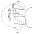
図7は第1壁540にある液体排出孔5403の構造概略図を示し、本願の実施例において、第1壁540は第1サブ壁5401及び第2サブ壁5402を含み、第1サブ壁5401と第2サブ壁5402との間にキャビティが形成され、第1サブ壁5401は筐体500の内壁であり、第2サブ壁5402は筐体500の外壁であり、第1サブ壁5401に液体排出孔5403が設けられ、即ち液体排出孔5403は第1壁540の第1サブ壁5401のみを貫通して、それにより液面の重力方向における高さが液体排出孔5403以上の液体はキャビティ内に収集され、筐体500内の液体を直ちに排出することができる。
Figure 7 shows a schematic diagram of the structure of the
図8に示すように、第1壁540は、筐体500の内外を連通するために用いられる通気孔5404をさらに含む。実際の応用において、液体排出孔5403は通気孔5404の一部であってもよく、それにより液体排出の役割を果たすと同時に、通気の役割を果たすことができる。
As shown in FIG. 8, the
図2に示すように、本願の実施例において、筐体500は、通気孔5404を遮蔽し(すなわち液体排出孔5403の位置を遮蔽する)、通気孔5404を通って筐体500の内部に流入したガスを凝縮するために用いられる凝縮部材550をさらに含む。凝縮部材550によって、筐体500の内部に流入するガスを予め凝縮することができ、凝縮後の液体を所定の位置に収集することができ、ガスが筐体500内に拡散した後に凝縮が発生しても、凝縮した液体が筐体500内の各位置に分散することを回避して、凝縮水を収集する目的を達成し、凝縮水の排出に役立つ。
2, in the embodiment of the present application, the
本願の実施例において、凝縮部材550は筐体500の内表面の、通気孔5404に対向する位置に設置され、それによりガスが通気孔5404から流入する時に、最初に凝縮部材550に接触し、ガスが筐体内で凝縮して筐体内部の導電部材に接触することを防止するという目的を達成する。
In the present embodiment, the
実際の応用において、図3に示すように、筐体500は、電池200の温度を調節するために用いられる熱管理部材560をさらに含み、熱管理部材560は第1壁540と交差し、第1壁540を介して筐体500の内部に入り、電池200の温度調節を実現する。熱管理部材560は水冷プレート等の部材であってもよく、本願の実施例はこれについて特に限定しない。
In practical applications, as shown in FIG. 3, the
引き続き図3を参照し、本願の実施例において、凝縮部材550の第1部分は熱管理部材560に沿って延伸して、上記熱管理部材560に取り付けられ、それにより凝縮部材550は熱管理部材560と熱伝達を行うことができるようになり、凝縮部材550は良好な凝縮効果を有する。凝縮部材550の第2部分は、通気孔5404を遮蔽するように第1壁540に沿って延伸し、通気孔5404から入ったガスが凝縮された凝縮水も凝縮部材550内に収集され、凝縮水が筐体500の他の位置に流れることを回避して、凝縮水の排出に役立つ。
Continuing to refer to FIG. 3, in the embodiment of the present application, the first part of the
実際の応用において、凝縮部材550の構造形式は様々であり、本願の実施例において、凝縮部材550はフード状構造であってもよく、該フード状構造は通気孔5404を遮蔽することができ、通気孔5404から入ったガスはフード状構造に接触し、且つフード状構造において凝縮させることができ、且つ凝縮した凝縮水はフード状構造に沿って凝縮部材550の箇所に収集することができる。
In practical applications, the structure of the
本願の実施例において、凝縮部材550と筐体500で囲まれた空間は一方向重力弁520の第1貫通孔523と連通し、凝縮部材550内に収集された凝縮水を一方向重力弁520に流すことができ、液体の重力が閾値に達すると、第1貫通孔523から排出される。
In the embodiment of the present application, the space surrounded by the
引き続き図2及び図8を参照すると、フード状構造の凝縮部材550は、通気孔5404の周囲の第1壁540の領域に取り付けられ、且つガスを筐体500に流入させるための第1開口5501を有する。フード状構造内で凝縮されたガスは、第1開口5501から筐体500内に入る。上記ガスは既に1回凝縮されているため、筐体500内に入ったガスが再び凝縮する確率は低下し、凝縮したとしても、発生した凝縮水が多すぎることで安全上のリスクをもたらすことはない。
With continued reference to Figures 2 and 8, the condensing
本願の実施例において、第1開口5501は、重力方向とは反対の方向であるフード状構造の第1方向に設けられる。
In this embodiment, the
実際の応用において、電池セル400に熱暴走が発生した時に、電池セル400の内部から排出された高温高圧の排出物がより深刻な損害をもたらすことを防止するために、通常は筐体500の内部に消防システムが設置され、電池セル400に対する消防を実施する。
In practical applications, when thermal runaway occurs in the
本願の実施例において、第1開口5501の位置は消防システムの配管の接続箇所と対向していてもよく、消防システムの配管の接続箇所に流体漏れが発生した場合、第1開口5501は消防システムの配管の接続箇所に漏れた流体を収集することができ、それにより消防システムの配管の接続箇所に漏れた流体が筐体500の内部に流れて電池200に影響を与えることを回避する。
In the embodiment of the present application, the position of the
実際の応用において、第1開口5501のサイズを大きく設定することができ、消防システムの配管の接続箇所から漏れた流体を受け止めることができるものであれば、本願の実施例は具体的なサイズを限定しない。
In practical applications, the size of the
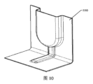
実際の応用において、フード状構造の第1壁540における投影面は様々な形状、例えば、図9に示す矩形面、図10に示すU形面、図11に示すV形面等を有してもよく、本願の実施例はこれについて特に限定しない。且つフード状構造の具体的な寸法は、筐体500が実際に収容可能な空間の大きさに基づいて決定することができ、本願の実施例はこれについて特に限定しない。
In practical applications, the projection surface of the
図9~図11に示すように、凝縮部材550のフード状構造に、フード状構造の凝縮水を一方向重力弁520に誘導するために用いられる流路5502がさらに設置される。凝縮部材550の、流路5502の両側の部分は、第1壁540に取り付けられる。
As shown in Figures 9 to 11, the hood-like structure of the
実際の応用において、上記取り付けは溶接、接着等の様々な接続方式であってもよく、本願の実施例はこれについて限定しない。 In practical applications, the above attachment may be by various connection methods such as welding, adhesives, etc., and the embodiments of this application are not limited thereto.
本願の実施例において、フード状構造は流路5502に対向する第2開口5503を有し、第2開口5503はフード状構造の凝縮水を流路5502に誘導し、且つ流路5502を通して一方向重力弁520に流入させるために用いられ、一方向重力弁520はさらに、流路5502内の凝縮水の重力が上記閾値に達した時に、流路5502内の凝縮水を筐体500から排出するために用いられる。第2開口5503は重力方向であるフード状構造の第2方向に設けることができる。
In the embodiment of the present application, the hood-like structure has a
実際の応用において、流路5502を細いストリップ状に設計することができ、それにより流路の高さを大きくし、液体の圧力を増加させて、流路内の液体が一方向重力弁520の閾値に達し、且つ一方向重力弁が直ちに開くことを保証する。
In practical applications, the flow path 5502 can be designed as a thin strip, which increases the height of the flow path and increases the liquid pressure to ensure that the liquid in the flow path reaches the threshold of the one-
図12に示すように、筐体500は、筐体500の内外の圧力を平衡させるための圧力平衡機構570をさらに含む。実際の応用において、圧力平衡機構570は筐体にある通気孔5404に取り付けることができ、且つ筐体500の外部ガスは圧力平衡機構570を通して筐体500の内部に流入させることができる。
As shown in FIG. 12, the
図13に示すように、本願の実施例において、筐体500は、筐体500の内表面に設置される液体貯蔵部材580をさらに含み、液体貯蔵部材580は、筐体500内の液体の液面における重力方向に沿った高さが液体貯蔵部材580の高さに達する時に、液体貯蔵部材580に流入する液体を収集し、且つ液体貯蔵部材580に流入した液体を一方向重力弁520に排出するために用いられる。
As shown in FIG. 13, in an embodiment of the present application, the
実際の応用において、液体貯蔵部材580は高さ制限板5801及び導流板5802を含み、高さ制限板5801は第1サブ壁5401の内表面と接触し、且つ高さ制限板5801と第1サブ壁5401との間に重力方向に沿って、上部が開口した液体高さ制限キャビティ5803が形成され、液体高さ制限キャビティ5803は、液体の表面が重力方向において液体高さ制限キャビティ5803より高い場合、液体を流入させることに用いられるように構成される。導流板5802は載置板510の電池セル400に向けられた表面と接触し、導流板5802と載置板510との間に導流路が設けられ、導流路の両端はそれぞれ液体高さ制限キャビティ5803及び一方向重力弁520に連通し、導流路は液体高さ制限キャビティ5803内の液体を一方向重力弁520に排出するために用いられる。
In practical application, the liquid storage member 580 includes a height limiting plate 5801 and a
他の態様によれば、本願は上記の筐体500を含む電池であって、筐体500は電池200を収容するために用いられる電池をさらに提供する。ここで、筐体500の具体的な構造形態及び動作原理は上記実施例において詳細に説明しており、本実施例はこれ以上説明しない。
According to another aspect, the present application further provides a battery including the above-mentioned
以上より、本願の実施例が提供する電池200は、上記の筐体500を設置し、筐体500に一方向重力弁520を設置することにより、一方向重力弁520の閾値に基づいて筐体500内の液体を排出するタイミングを決定し、筐体500内の液体が多すぎる場合、筐体500内の液体を直ちに排出して、安全上のリスクを減少させ、電池200の耐用年数を延ばすことができる。筐体500内の液体が少なく、一方向重力弁520を開けるには足りない時には、筐体内に残された少量の液体は電池200の安全性に影響を与えない状況で、筐体500内部の電池200の温度を下げる役割を果たすことができる。
In view of the above, the
他の態様によれば、上記の電池200を含む電力消費装置であって、電池200は電気エネルギーを供給するために用いられる電力消費装置をさらに提供する。電池200は筐体500内に設置され、且つ筐体500は内部の液体を直ちに排出して、液体が筐体500内に長時間滞留することによる安全上のリスクを回避することができる。ここで、筐体500の具体的な構造形態及び動作原理は上記実施例において詳細に説明しており、本実施例はこれ以上説明しない。
According to another aspect, there is further provided a power consumption device including the above-mentioned
以上は本願の実施例の電池及び電力消費装置を説明し、以下では本願の実施例の電池の製造方法及びその装置を説明し、ここで詳細に説明しない部分は上記各実施例を参照することができる。 The above describes the battery and power consumption device of the embodiment of the present application, and below describes the battery manufacturing method and device of the embodiment of the present application. For parts that are not described in detail here, please refer to the above embodiments.
他の態様によれば、本願の実施例は、電池の製造方法をさらに提供し、図14に示すように、該電池の製造方法は以下のステップを含むことができる。 According to another aspect, the embodiment of the present application further provides a method for manufacturing a battery, which may include the following steps, as shown in FIG. 14:
ステップS1410では、電池を載置板に取り付ける。 In step S1410, the battery is attached to the mounting plate.
ステップS1420では、前記載置板に一方向重力弁が設置され、前記一方向重力弁は前記筐体内の液体の重力が閾値より小さい時に閉じて、且つ前記筐体内の液体の重力が前記閾値に達した時に開くように構成され、それにより前記一方向重力弁を介して前記液体を排出させる。 In step S1420, a one-way gravity valve is installed on the loading plate, and the one-way gravity valve is configured to close when the gravity of the liquid in the housing is less than a threshold value and to open when the gravity of the liquid in the housing reaches the threshold value, thereby discharging the liquid through the one-way gravity valve.
筐体500の部分の実施例から分かるように、電池200は筐体500内に設置され、筐体500内の液体が多い場合、筐体500内に設置された一方向重力弁520を通して液体を排出することができ、それにより安全上のリスクを減少させ、電池200の耐用年数を延ばすことができる。
As can be seen from the example of the
筐体500の部分の実施例から分かるように、筐体500はさらに他の部材を含み、対応する方法によってこれらの部材を製造して、最終的に必要とされる液体を排出しやすい筐体500を得ることができる。実際の応用において、任意の可能な関連部材の製造及び関連部材の接続方法はいずれも本願の実施例の保護範囲内に属し、本願の実施例はここでの説明を省略する。
As can be seen from the embodiment of the part of the
他の態様によれば、本願の実施例は電池の製造装置をさらに提供し、図15は、本願の実施例に係る電池の製造装置のブロック図を示す。図15に示すように、該電池の製造装置1500は、第1装置1510と、第2装置1520とを含むことができる。
According to another aspect, the present embodiment further provides a battery manufacturing apparatus, and FIG. 15 shows a block diagram of the battery manufacturing apparatus according to the present embodiment. As shown in FIG. 15, the
第1装置1510は、電池を載置板に取り付けるために用いられ、載置板は筐体の一部に属し、筐体の底部に設置されることができる。 The first device 1510 is used to attach the battery to a mounting plate, which is part of the housing and can be installed at the bottom of the housing.
第2装置1520は、前記載置板に一方向重力弁が設置されるために用いられることができる。
The
一方向重力弁は筐体内の液体の重力が閾値より小さい時に閉じて、且つ筐体内の液体の重力が前記閾値に達した時に開くように構成され、それにより前記一方向重力弁を介して前記液体を排出させる。 The one-way gravity valve is configured to close when the gravity of the liquid in the housing is less than a threshold value and to open when the gravity of the liquid in the housing reaches the threshold value, thereby allowing the liquid to be discharged through the one-way gravity valve.
上記の各電池の製造装置の具体的な詳細は対応する電池用筐体の実施例で詳細に説明しているため、ここでの説明は省略する。 Specific details of the manufacturing equipment for each of the above batteries are explained in detail in the examples of the corresponding battery casings, so explanations will be omitted here.
本願の上記特許請求される主題及び各実施例における特徴の間は相互に参照することができ、構造が許容される場合、当業者は異なる実施例における技術的特徴を柔軟に組み合わせて、より多くの実施例を形成することができる。 The features of the subject matter claimed herein and each embodiment may be cross-referenced, and where structure permits, a person skilled in the art may flexibly combine technical features of different embodiments to form more embodiments.
以上、本発明が提供する電池、電力消費装置、電池の製造方法及びその装置について詳細を紹介した。本明細書は具体的な実施例を用いて本願の原理及び実施形態を説明したが、以上の実施例の説明は、本願の方法及びその中心となる発想の理解を助けるためのものに過ぎない。指摘すべきこととして、当業者であれば、本願の原理から逸脱しない前提で、さらにいくつかの改良及び変更を行うことができ、それらの改良及び変更も本願の保護範囲とみなされるべきである。 The above provides a detailed introduction of the battery, power consumption device, battery manufacturing method, and device provided by the present invention. This specification uses specific examples to explain the principles and embodiments of the present application, but the explanation of the above examples is merely intended to aid in the understanding of the method and central idea of the present application. It should be noted that a person skilled in the art may make further improvements and modifications without departing from the principles of the present application, and such improvements and modifications should also be considered to be within the scope of protection of the present application.
200 電池
500 筐体
510 載置板
520 一方向重力弁
200
Claims (22)
前記載置板に設置される一方向重力弁と、
前記載置板に接続されて前記電池を収容する収容キャビティを形成するように構成される第1壁であって、前記第1壁に液体排出孔が設けられ、前記液体排出孔は前記筐体内の前記液体の液面の重力方向における高さが前記液体排出孔以上の時に、前記液体排出孔の高さを超える液体を排出するために用いられる、第1壁と、
を含み、
前記一方向重力弁は筐体内の液体の重力が閾値より小さい時に閉じて、且つ前記筐体内の液体の重力が前記閾値に達した時に開くように構成され、それにより前記一方向重力弁を介して前記液体を排出させるために用いられる、電池用筐体。 A mounting plate for mounting the battery;
A one-way gravity valve installed on the mounting plate;
a first wall configured to be connected to the mounting plate and to form an accommodating cavity for accommodating the battery, the first wall being provided with a liquid drainage hole, the liquid drainage hole being used to drain liquid exceeding a height of the liquid drainage hole when a height of a liquid surface of the liquid in the housing in a direction of gravity is equal to or greater than the liquid drainage hole;
Including,
A battery housing, wherein the one-way gravity valve is configured to close when the gravity of the liquid in the housing is less than a threshold value, and to open when the gravity of the liquid in the housing reaches the threshold value, thereby allowing the liquid to be drained through the one-way gravity valve.
前記液体排出部材は第1貫通孔を有し、前記液体排出部材は前記筐体内の液体の重力が前記閾値に達した時に前記第1貫通孔を介して前記液体を排出するために用いられ、
前記可動アセンブリは、前記液体排出部材に取り付けられ且つ前記第1貫通孔に対して移動させることができ、それにより前記可動アセンブリは、前記筐体内の液体の重力が前記閾値より小さい時に前記第1貫通孔を密封し、前記筐体内の液体の重力が前記閾値に達した時に前記第1貫通孔が開く、請求項1に記載の筐体。 The one-way gravity valve includes a liquid discharge member and a movable assembly;
the liquid discharge member has a first through hole, and the liquid discharge member is used to discharge the liquid through the first through hole when the gravity of the liquid in the housing reaches the threshold value;
2. The housing of claim 1, wherein the movable assembly is attached to the liquid ejection member and is movable relative to the first through hole, such that the movable assembly seals the first through hole when the gravity of the liquid in the housing is less than the threshold and the first through hole opens when the gravity of the liquid in the housing reaches the threshold.
Applications Claiming Priority (1)
| Application Number | Priority Date | Filing Date | Title |
|---|---|---|---|
| PCT/CN2020/121996 WO2022082393A1 (en) | 2020-10-19 | 2020-10-19 | Box body for battery, battery, electric apparatus, and battery manufacturing method and device |
Publications (2)
| Publication Number | Publication Date |
|---|---|
| JP2023525281A JP2023525281A (en) | 2023-06-15 |
| JP7513751B2 true JP7513751B2 (en) | 2024-07-09 |
Family
ID=81289524
Family Applications (1)
| Application Number | Title | Priority Date | Filing Date |
|---|---|---|---|
| JP2022567658A Active JP7513751B2 (en) | 2020-10-19 | 2020-10-19 | Battery housing, battery, power consumption device, battery manufacturing method and device |
Country Status (6)
| Country | Link |
|---|---|
| US (1) | US11894583B2 (en) |
| EP (1) | EP4064449B1 (en) |
| JP (1) | JP7513751B2 (en) |
| KR (1) | KR102707154B1 (en) |
| HU (1) | HUE068408T2 (en) |
| WO (1) | WO2022082393A1 (en) |
Families Citing this family (4)
| Publication number | Priority date | Publication date | Assignee | Title |
|---|---|---|---|---|
| CN116557615B (en) * | 2023-07-11 | 2023-12-01 | 宁德时代新能源科技股份有限公司 | Electromagnetic liquid discharge valve, battery and electricity utilization device |
| CN116683116B (en) * | 2023-07-20 | 2023-12-22 | 宁德时代新能源科技股份有限公司 | Liquid discharge valve of battery, battery and electricity utilization device |
| CN117317446A (en) * | 2023-11-09 | 2023-12-29 | 湖北亿纬动力有限公司 | A kind of vapor chamber and battery component |
| DE212024000109U1 (en) * | 2023-11-09 | 2025-07-21 | Eve Power Co., Ltd. | Battery and battery pack |
Citations (5)
| Publication number | Priority date | Publication date | Assignee | Title |
|---|---|---|---|---|
| JP2012094313A (en) | 2010-10-26 | 2012-05-17 | Sanyo Electric Co Ltd | Battery unit cooling structure |
| JP2013086641A (en) | 2011-10-18 | 2013-05-13 | Mitsubishi Motors Corp | Battery pack mounting structure for electric vehicle |
| JP2017073211A (en) | 2015-10-05 | 2017-04-13 | トヨタ自動車株式会社 | Hermetically sealed type battery |
| CN207441762U (en) | 2017-11-29 | 2018-06-01 | 宁德时代新能源科技股份有限公司 | Box assembly and battery case |
| JP2019185970A (en) | 2018-04-06 | 2019-10-24 | トヨタ自動車株式会社 | Power storage device |
Family Cites Families (9)
| Publication number | Priority date | Publication date | Assignee | Title |
|---|---|---|---|---|
| WO2006098130A1 (en) * | 2005-03-14 | 2006-09-21 | Nec Lamilion Energy, Ltd. | Housing for film-coated electric device |
| WO2010064255A1 (en) | 2008-12-05 | 2010-06-10 | Shatendra Kumar Sharma | An improved battery casing for enhanced battery performance and life |
| KR102198000B1 (en) * | 2014-02-17 | 2021-01-04 | 삼성에스디아이 주식회사 | Case for battery pack |
| CN203910893U (en) * | 2014-05-28 | 2014-10-29 | 沭阳天泓工贸有限公司 | High-flame-retardancy ABS reversible battery outer shell |
| JP2016062712A (en) * | 2014-09-17 | 2016-04-25 | トヨタ自動車株式会社 | Manufacturing method of all-solid lithium secondary battery |
| CN105762428B (en) * | 2016-03-03 | 2019-06-04 | 宁德时代新能源科技股份有限公司 | battery pack |
| CN207250619U (en) | 2017-09-11 | 2018-04-17 | 惠州市蓝微新源技术有限公司 | A kind of check valve of battery pack babinet |
| CN207441811U (en) * | 2017-11-20 | 2018-06-01 | 宁德时代新能源科技股份有限公司 | Babinet and battery pack |
| CN111584792B (en) * | 2020-04-21 | 2022-11-29 | 重庆金康动力新能源有限公司 | Battery module |
-
2020
- 2020-10-19 WO PCT/CN2020/121996 patent/WO2022082393A1/en not_active Ceased
- 2020-10-19 EP EP20957976.2A patent/EP4064449B1/en active Active
- 2020-10-19 JP JP2022567658A patent/JP7513751B2/en active Active
- 2020-10-19 KR KR1020227038503A patent/KR102707154B1/en active Active
- 2020-10-19 HU HUE20957976A patent/HUE068408T2/en unknown
-
2022
- 2022-11-10 US US18/054,314 patent/US11894583B2/en active Active
Patent Citations (5)
| Publication number | Priority date | Publication date | Assignee | Title |
|---|---|---|---|---|
| JP2012094313A (en) | 2010-10-26 | 2012-05-17 | Sanyo Electric Co Ltd | Battery unit cooling structure |
| JP2013086641A (en) | 2011-10-18 | 2013-05-13 | Mitsubishi Motors Corp | Battery pack mounting structure for electric vehicle |
| JP2017073211A (en) | 2015-10-05 | 2017-04-13 | トヨタ自動車株式会社 | Hermetically sealed type battery |
| CN207441762U (en) | 2017-11-29 | 2018-06-01 | 宁德时代新能源科技股份有限公司 | Box assembly and battery case |
| JP2019185970A (en) | 2018-04-06 | 2019-10-24 | トヨタ自動車株式会社 | Power storage device |
Also Published As
| Publication number | Publication date |
|---|---|
| US11894583B2 (en) | 2024-02-06 |
| EP4064449A1 (en) | 2022-09-28 |
| KR102707154B1 (en) | 2024-09-13 |
| US20230084044A1 (en) | 2023-03-16 |
| WO2022082393A1 (en) | 2022-04-28 |
| EP4064449B1 (en) | 2024-07-10 |
| JP2023525281A (en) | 2023-06-15 |
| EP4064449A4 (en) | 2023-09-27 |
| HUE068408T2 (en) | 2024-12-28 |
| EP4064449C0 (en) | 2024-07-10 |
| KR20220163454A (en) | 2022-12-09 |
Similar Documents
| Publication | Publication Date | Title |
|---|---|---|
| JP7700235B2 (en) | Battery housing, battery, power consumption device, and battery manufacturing method and device | |
| JP7513751B2 (en) | Battery housing, battery, power consumption device, battery manufacturing method and device | |
| CN112018320B (en) | Box for battery, electric device, method and equipment for preparing battery | |
| JP7350213B2 (en) | Batteries, power consumption devices, battery manufacturing methods and devices | |
| JP7696902B2 (en) | Battery housing, battery, power consumption device, battery manufacturing method and device | |
| JP7784521B2 (en) | Batteries, power consumption devices, battery manufacturing methods and devices | |
| CN112018300B (en) | Battery box, battery, electric device, and method and device for preparing battery | |
| JP7580575B2 (en) | Battery, electric device, and battery manufacturing method and device | |
| JP2023528296A (en) | BATTERY, POWER CONSUMER, METHOD AND APPARATUS FOR BATTERY MANUFACTURE | |
| JP7417763B2 (en) | Batteries, power consuming devices, methods and apparatus for manufacturing batteries | |
| JP2023524121A (en) | Batteries, electrical devices, methods and devices for manufacturing batteries | |
| US12142787B2 (en) | Battery, electric apparatus, and method and device for preparing battery | |
| WO2022082391A1 (en) | Battery, electric apparatus, and battery manufacturing method and device | |
| US11926225B2 (en) | Case of battery, battery, power consumption device, and method and device for producing battery | |
| CN112018322B (en) | Battery box, battery, electric device, and method and device for preparing battery | |
| EP4254591B1 (en) | Battery, electrical apparatus, and method and apparatus for manufacturing battery | |
| JP7473737B2 (en) | Battery housing, battery, power utilization device, and method and device for manufacturing battery | |
| JP2023544070A (en) | Batteries, power consumption devices, battery manufacturing methods and devices | |
| CN223462282U (en) | Battery module and single battery | |
| JP7741310B2 (en) | Housing, battery, electrical device, method and apparatus for manufacturing battery |
Legal Events
| Date | Code | Title | Description |
|---|---|---|---|
| A521 | Request for written amendment filed |
Free format text: JAPANESE INTERMEDIATE CODE: A523 Effective date: 20221107 |
|
| A621 | Written request for application examination |
Free format text: JAPANESE INTERMEDIATE CODE: A621 Effective date: 20221107 |
|
| RD02 | Notification of acceptance of power of attorney |
Free format text: JAPANESE INTERMEDIATE CODE: A7422 Effective date: 20230601 |
|
| RD04 | Notification of resignation of power of attorney |
Free format text: JAPANESE INTERMEDIATE CODE: A7424 Effective date: 20230721 |
|
| A977 | Report on retrieval |
Free format text: JAPANESE INTERMEDIATE CODE: A971007 Effective date: 20231205 |
|
| A131 | Notification of reasons for refusal |
Free format text: JAPANESE INTERMEDIATE CODE: A131 Effective date: 20231211 |
|
| A521 | Request for written amendment filed |
Free format text: JAPANESE INTERMEDIATE CODE: A523 Effective date: 20240229 |
|
| TRDD | Decision of grant or rejection written | ||
| A01 | Written decision to grant a patent or to grant a registration (utility model) |
Free format text: JAPANESE INTERMEDIATE CODE: A01 Effective date: 20240603 |
|
| A61 | First payment of annual fees (during grant procedure) |
Free format text: JAPANESE INTERMEDIATE CODE: A61 Effective date: 20240627 |
|
| R150 | Certificate of patent or registration of utility model |
Ref document number: 7513751 Country of ref document: JP Free format text: JAPANESE INTERMEDIATE CODE: R150 |