JP7514432B2 - Lighting equipment - Google Patents
Lighting equipment Download PDFInfo
- Publication number
- JP7514432B2 JP7514432B2 JP2022066836A JP2022066836A JP7514432B2 JP 7514432 B2 JP7514432 B2 JP 7514432B2 JP 2022066836 A JP2022066836 A JP 2022066836A JP 2022066836 A JP2022066836 A JP 2022066836A JP 7514432 B2 JP7514432 B2 JP 7514432B2
- Authority
- JP
- Japan
- Prior art keywords
- lighting
- emergency
- plate
- fixture
- lighting fixture
- Prior art date
- Legal status (The legal status is an assumption and is not a legal conclusion. Google has not performed a legal analysis and makes no representation as to the accuracy of the status listed.)
- Active
Links
Images


Landscapes
- Arrangement Of Elements, Cooling, Sealing, Or The Like Of Lighting Devices (AREA)
- Non-Portable Lighting Devices Or Systems Thereof (AREA)
- Fastening Of Light Sources Or Lamp Holders (AREA)
Description
本発明の実施形態は、非常灯組み込み形の照明装置に関する。 An embodiment of the present invention relates to a lighting device with an integrated emergency light.
例えば住宅や、商業施設、工場等の天井面に直接取り付けられる従来の照明装置の一例として、常用点灯用光源を有する照明装置の器具本体内に非常灯を組み込んだ非常灯組み込み形の照明装置が開発されている。この非常灯組み込み形の照明装置は、通常時は商用電源のような外部電源の電力を用いて光源を点灯させ、外部電源からの給電が停止した非常時には、内蔵した蓄電池の電力を用いて光源を点灯させる構成になっている。 As an example of a conventional lighting device that can be directly attached to the ceiling of a house, commercial facility, factory, etc., a lighting device with an emergency light built in has been developed that has an emergency light built into the fixture body of a lighting device that has a light source for normal use. This lighting device with an emergency light built in is configured to normally light the light source using power from an external power source such as a commercial power source, and in an emergency when the power supply from the external power source is stopped, light the light source using power from a built-in storage battery.
天井面に形成された装着用の凹部(埋め込み穴)に埋め込み状態で装着される埋め込み形の照明装置(埋め込み器具)は、リニューアル施工をする場合に、埋め込み穴の寸法は、標準器具と同じであることが望ましい。そのため、従来の組み込み形の非常灯器具では、標準器具と埋め込み穴の寸法を同じにするために、常用光源部の全長を標準器具に対し短くし、空いたスペースに非常用点灯用の構成部品を組み込む構成としていた。 When a recessed lighting device (recessed fixture) is installed in a recessed mounting hole (recessed hole) formed in the ceiling surface, it is desirable for the dimensions of the recessed hole to be the same as that of a standard fixture when undergoing renovation work. Therefore, in conventional built-in emergency lighting fixtures, in order to make the dimensions of the recessed hole the same as those of a standard fixture, the overall length of the normal light source unit was made shorter than that of a standard fixture, and the emergency lighting components were installed in the freed space.
上記従来構造の非常灯組み込み形の照明装置の場合、標準器具と異なる寸法形状の常用点灯用光源の機種を新たにラインナップしなければならない。このため、新たな常用点灯用光源のラインナップ分の開発工数が増えるとともに、在庫が増大する等の課題がある。 In the case of lighting devices with built-in emergency lights of the conventional structure described above, new models of light sources for normal use with different dimensions and shapes from standard fixtures must be added to the lineup. This increases the amount of development work required for the lineup of new light sources for normal use, and creates issues such as an increase in inventory.
実施形態の照明装置によれば、長尺状の常用点灯用光源と、器具本体と、非常用照明器具とを具備する。器具本体は、第1面と第1面の裏面側である第2面とを有する底板と、側板とを有し、底板の第1面と側板とにより形成される開口を覆うように常用点灯用光源が着脱可能に取り付けられる。非常用照明器具は、器具本体の底板の第2面に固定される板状の部材を介して、常用点灯用光源の長手方向と直交する方向に隣接して配置される。 According to an embodiment, the lighting device includes an elongated normal operation light source, a fixture body, and an emergency lighting fixture. The fixture body has a bottom plate having a first surface and a second surface that is the reverse side of the first surface , and a side plate, and the normal operation light source is detachably attached so as to cover an opening formed by the first surface of the bottom plate and the side plate. The emergency lighting fixture is disposed adjacent to the normal operation light source in a direction perpendicular to the longitudinal direction thereof via a plate-shaped member fixed to the second surface of the bottom plate of the fixture body.
本発明によれば、器具本体内のスペースを有効利用できることが期待できる。 This invention is expected to enable effective use of the space inside the device body.
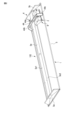
図1乃至図11は、第1の実施の形態を示す。図1は、例えば住宅や、商業施設、工場等の天井面に直接取り付けられる第1の実施の形態の非常灯組み込み形の照明装置100の全体の外観を示す斜視図である。図2は、照明装置100の裏面側を示す斜視図である。
Figures 1 to 11 show the first embodiment. Figure 1 is a perspective view showing the overall appearance of an emergency light-embedded
本実施形態の照明装置100は、図示しない天井面に形成された装着用の凹部に埋め込み状態で装着される埋め込み形の照明器具である。この照明装置100は、常用の第1の照明器具1と、非常用の第2の照明器具2と、を具備する。
The
本実施形態の照明装置100の第1の照明器具1は、図1に示すように、長尺状の常用点灯用光源としての直管形のLEDバー3と、LEDバー3を保持する器具本体4とを備える。さらに、第1の照明器具1は、通常時にLEDバー3を点灯させる図示しない常用電源ユニットと、常用電源ユニットを外部電源に接続する図示しない電源端子台と、反射板4aとを有する常用点灯用の構成部品を備える。LEDバー3は、複数種類の機種が予め準備されており、適宜選択的に使用可能になっている。
As shown in FIG. 1, the
第1の照明器具1の器具本体4は、図1に示すように、常用点灯用の構成部品を収容する埋め込みシャーシであるケース部材5を有する。このケース部材5は、対向配置された一対の端板5a、5bを有し、さらにこれらの端板5a、5b間に配置された一対の傾斜板5c、5dと、図2に示すように断面形状がほぼU字状のチャンネル部材5e(図3参照)とを有する。チャンネル部材5eは、図3に示すように底板5e1と、この底板5e1の両端に連接された一対の側板5e2、5e3とを有する。各側板5e2、5e3の図3中で下端部には、傾斜板5c、5dの各上端部がそれぞれ連結されている。これら一対の傾斜板5c、5dと、チャンネル部材5eとは金属製板部材を用いて一体に成形されている。
As shown in FIG. 1, the
本実施形態では、器具本体4は、図3中で下方を開放している。そして、一対の傾斜板5c、5dは、反射板4aとして機能する。一対の傾斜板5c、5d間のチャンネル部材5eは、内部空間に常用点灯用の構成部品を収容する収容部を形成している。このチャンネル部材5eの内部空間には、常用電源ユニットと、電源端子台などの常用点灯用の構成部品を収容している。このチャンネル部材5eの両端部には、LEDバー3を取り付ける図示しないソケットがそれぞれ配置されている。これらのソケットにはLEDバー3の両端の口金部がそれぞれ着脱可能に結合されている。これにより、チャンネル部材5eの下面の開口部にLEDバー3が着脱可能に装着され、このチャンネル部材5eの下面の開口部に常用点灯用光源の装着部5fが形成されている。
In this embodiment, the
また、ソケットからLEDバー3に電力が供給され、常用電源ユニットを介して通常時にLEDバー3を点灯させる。器具本体4も複数種類の機種が予め準備されており、適宜選択的に使用可能になっている。LEDバー3と器具本体4との組み合わせも任意に選択可能になっている。
Power is also supplied from the socket to the
第1の照明器具1の器具本体4には、一方の傾斜板5dの一方の端板5b側の端部に、非常用の第2の照明器具2をLEDバー3の長手方向と直交する方向に横並び状態で隣接配置している。本実施形態では、器具本体4の反射板4aの一方の傾斜板5dに長方形状の切欠き部分6を設け、この切欠き部分6に第2の照明器具2を装着している。
The
図3は、器具本体4の内部構造を示す横断面図、図4は、第2の照明器具2の取付け状態を示す要部の斜視図、図5は、器具本体4から第2の照明器具2を取り外した状態を説明するための斜視図である。なお、図3は、本実施形態の照明装置100を天井面に取り付けた状態を示している。また、図8は、第2の照明器具2の分解斜視図である。
Figure 3 is a cross-sectional view showing the internal structure of the
第2の照明器具2は、LED非常灯(非常用点灯用の非常用光源)7と、LED非常灯7を保持する非常灯器具本体8とを備える。LED非常灯7は、図8に示すように多数のLEDチップを基板に直接実装した構造のチップオンボードであるCOB基板9と、レンズ10と、パッキンと、レンズ固定金具12とを備える。
The
非常灯器具本体8は、非常用電源の一例である蓄電池13と、非常用点灯ユニット14とを有する非常用点灯用の構成部品を備える。非常用点灯ユニット14は、図8に示すようにシャーシ15と、ユニット樹脂ケース16と、ユニット基板17と、サブ基板18と、光源放熱板を兼ねる電池収納用板金部品19と、を具備する。サブ基板18は、例えば赤・緑モニターや、点検SWリモコン受光部の実装基板である。
The emergency lighting device
シャーシ15は、図8中で下面に配置される底板15aと、この底板15aの図8中で前端側に配置される前端板15bと、後端側に配置される後端板15cとを有する。シャーシ15の前端板15bの上端部には、内側に向けて直角に折り曲げた折り曲げ部15b1が形成されている。この折り曲げ部15b1には、ねじ穴15b2が形成されている。
シャーシ15の後端板15cの上端部には、内側に向けて直角に折り曲げた幅広の折り曲げ部15c1が形成されている。この折り曲げ部15c1には、2つのねじ穴15c2と、電池収納用板金部品19との位置決め用の角穴15c3とが形成されている。
The
A wide bent portion 15c1 is formed by bending the upper end of the
ユニット樹脂ケース16は、シャーシ15上に配置される。このユニット樹脂ケース16は、上面側に蓄電池13を保持する電池受部16aと、電池受部16aよりも高さが高く立設された立設部16bとを有する。図9に示すように電池受部16aと、立設部16bとの間の境界部分には、電池受部16aの上に装着される蓄電池13の角部の形状に合わせた湾曲面16a1が形成されている。電池受部16aの下方にはシャーシ15の底板15aとの間に適宜のスペースSが形成されている。このスペースSには、ユニット基板17の前端部分が挿入状態で装着されている。立設部16bの上部には、サブ基板18を保持する基板保持部16cが形成されている。
The
図9に示すようにユニット樹脂ケース16の下部には、ユニット基板17が装着されている。このユニット樹脂ケース16の立設部16bの基板保持部16cには、サブ基板18が装着されている。
As shown in FIG. 9, a
ユニット基板17は、図11に示すように矩形状の基板本体17aの一端側の両側を切欠させた切欠部17b1、17b2を有する幅狭部分17bと、基板本体17aの両側の切欠部17b1、17b2が形成されていない幅広部分17cとを含むT字状の基板形状を有する。基板本体17aは、幅広部分17cの一側部に入力側の1次側回路20aを配置し、幅広部分17cの他側部に出力側の2次側回路20bを配置している。さらに、基板本体17aには、幅広部分17cにおける1次側回路20aを配置した側の切欠部17b1との対向部に、1次側回路20aに接続させた第1コネクタ21aを配設している。
As shown in FIG. 11, the
この第1コネクタ21aには、入力側のAC電源に接続される1次側配線を接続している。また、幅広部分17cにおける2次側回路20bを配置した側の切欠部17b2との対向部に、2次側回路20bに接続させた第2コネクタ21bを配設している。この第2コネクタ21bには、2次側回路20b側の充電回路や、非常灯点灯回路などに接続される2次側配線を配置している。
The primary wiring connected to the input side AC power supply is connected to this
さらに、ユニット基板17には、幅広部分17cの1次側回路20aと2次側回路20bとの間にトランス回路20cを配置している。幅狭部分17bには、非常用点灯ユニット14を制御する制御回路20dを配置した。
Furthermore, a
図9に示すようにシャーシ15の底板15aと、ユニット樹脂ケース16の電池受部16aとの間には、ユニット基板17に接続される配線を収容する左右一対の配線収容部22a、22b(図10参照)が形成されている。一方の配線収容部22aには、第1コネクタ21aに接続される1次側配線23aが収容されている。他方の配線収容部22bには、第2コネクタ21bに接続される2次側配線23bが収容されている。
As shown in FIG. 9, a pair of left and right
電池収納用板金部品19は、シャーシ15の前端板15bおよび後端板15cの上端部にそれぞれねじ止め固定される。この電池収納用板金部品19の上には、LED非常灯7のCOB基板9が熱伝導性の高いグリースを介して装着される。さらに、COB基板9の上にレンズ10と、パッキンと、レンズ固定金具12とが順次積層された状態で、ねじによってレンズ固定金具12が電池収納用板金部品19とともにシャーシ15に共締め固定される。これにより、LED非常灯7の光源ユニット全体が一体的に組み付けられる。
The battery housing
さらに、電池収納用板金部品19の板面には、下向きに3つのガイド片25が形成されている。このガイド片25は、電池収納用板金部品19の板面に形成されたU字状の切り込み部分を下向きに切り起こして形成されている。1つのガイド片25は、シャーシ15の一方の側板15cの上端部の角穴15c3に挿入され、電池収納用板金部品19とシャーシ15との位置決め用に使用される。
In addition, three
電池収納用板金部品19とユニット樹脂ケース16の電池受部16aとの間には蓄電池13を収納する電池収納部31が形成されている。蓄電池13は、後述するとおりこの電池収納部31に第1の照明器具1のチャンネル部材5eの下面の開口部側から挿入される。このとき、電池収納用板金部品19のガイド片25によって蓄電池13がガイドされ、蓄電池13が電池収納用板金部品19の固定ねじに当たることが防止されている。そして、LED非常灯7の光源ユニットから発生する熱や、蓄電池13の熱を電池収納用板金部品19によって効率よく放熱することができる。
A
さらに、第2の照明器具2は、非常用点灯用の構成部品を保持する保持金具41と、化粧枠(カバー部材)42とを有する。保持金具41は、矩形平板状の底板41aと、この底板41aの両側に立設された2つの側板41b、41cと、底板41aの図8中で背面に立設された2つの背面板41d、41eとを有する。2つの側板41b、41cの図8中で前面には、第1の照明器具1の一方の傾斜板5dの傾斜に合わせた傾斜の切欠部41b1、41c1が形成されている。底板41aの前端部には、1つの舌片41fが前向きに突設されている。
The
2つの側板41b、41cの上端部には、それぞれ内側に直角に折り返した折曲部41b3、41c3が形成されている。同様に、2つの側板41b、41cの切欠部41b1、41c1の上縁部には、それぞれ内側に直角に折り返した折曲部41b3、41c3が形成されている。さらに、2つの背面板41d、41eの上端部には、それぞれ外側に直角に折り返した折曲部41d1、41e1が形成されている。これらの折曲部41d1、41e1と、2つの背面板41d、41eの上端部との接合部には、角穴41d2、41e2がそれぞれ形成されている。そして、第2の照明器具2の非常用点灯用の構成部品は、保持金具41の上に収容される状態で組み付けられている。このとき、シャーシ15は、後端板15cが2つの背面板41d、41e側に配置され、前端板15bが保持金具41の前面開口部側に配置される状態で組み付けられている。これにより、図7に示すように保持金具41の前面開口部側に蓄電池13の出し入れ口43が形成されている。
The upper ends of the two
化粧枠42は、平板状の天板42aと、この天板42aの図8中で前端を斜めに屈曲させた傾斜板42bとを有する。天板42aには、LED非常灯7のレンズ10を配置する円孔42a1と、この円孔42a1の横に配置された長孔42a2とが形成されている。
さらに、天板42aの図8中で背面側の端縁部には、保持金具41の角穴41d2、41e2とそれぞれ対応する位置に係合凸部42c1、42c2がそれぞれ形成されている。
天板42aの長孔42a2は、サブ基板18の上に配置された点検SW45と対応する位置に配置されている。
The
Furthermore, at the edge portion of the
The
傾斜板42bは、第1の照明器具1の一方の傾斜板5dの傾斜に合わせた傾斜角度で形成されている。この傾斜板42bの図8中で下端部には、保持金具41の舌片41fと対応する位置に舌片42b1が形成されている。
The
そして、化粧枠42は、係合凸部42c1、42c2がそれぞれ保持金具41の角穴41d2、41e2に挿入された状態で、傾斜板42bの舌片42b1が保持金具41の舌片41fと接合された状態でねじ止め固定されている。そして、化粧枠42は、係合凸部42c1、42c2と、保持金具41の角穴41d2、41e2との係合部を回動中心として保持金具41に対して回動可能に支持されている。これにより、例えば蓄電池13の出し入れ時などの作業時に必要に応じて化粧枠42を開閉して蓄電池13の出し入れ時などの作業を行うことができる。この化粧枠42を開閉操作時には、点検SW45が長孔42a2に沿って移動することで、点検SW45が化粧枠42に引っかかることを防止できる。
The
また、第2の照明器具2は、図5に示すように裏面側(保持金具41の底板41aの外面側)が第1の照明器具1の反射板4aに対し略C字形状の補強部材44を介して取り付けられている。補強部材44は、長板部材44aと、この長板部材44aの長手方向の両端にそれぞれ固定されるL字状の屈曲部材44b、44cとを有する。図3に示すように長板部材44aは、チャンネル部材5eの底板5e1に固定されている。一方の屈曲部材44bの末端部は、一方の傾斜板5cの端縁部、他方の屈曲部材44cの末端部は、他方の傾斜板5dの端縁部にそれぞれ固定されている。
As shown in FIG. 5, the back side (the outer surface side of the
また、第2の照明器具2は、器具本体4の反射板4aの切欠き部分6に装着した状態で、図3に示すように器具本体4の一部が切欠き部分6から反射板4aの下方に突出される状態で設置されている。そして、第2の照明器具2の器具本体4の大部分は、第1の照明器具1の反射板4aの裏側に埋設された状態で配置されている。そのため、第2の照明器具2の非常点灯用の構成部品は、第1の照明器具1の器具本体4を天井面に埋め込み状態で施工した際に天井面より奥まった位置に配置されている。これにより、天井面から非常用の第2の照明器具2の構成部品が突出している場合のように照明装置100を施工した空間において非常用の第2の照明器具2の構成部分が第1の照明器具1の器具本体4の外に露出されることがない。そのため、天井面から非常用の第2の照明器具2の構成部品が突出している場合のように第1の照明器具1の器具本体4の外から第2の照明器具2の構成部品が見えてしまうことがなく、外観が悪くなることを防止することができる。また、照明装置100の全体の梱包容積をコンパクトにすることができ、輸送費が高くなるという課題を解決できる。
In addition, the
さらに、第2の照明器具2は、器具本体4の反射板4aの切欠き部分6に装着した状態で、図3に示すように化粧枠42のLEDバー3側に傾斜板42bを設けた形状としている。これにより、LEDバー3からの放射光が非常用の第2の照明器具2によって遮られる量を少なくすることができる。そのため、LEDバー3の配光の遮断を低減することができる。
Furthermore, when the
また、本実施形態では、第2の照明器具2の化粧枠42は、LED非常灯7の周囲に平板状の天板42aを設け、この天板42aを天井面と平行に設けている。このように、非常点灯用構成部品の化粧枠42における光源面が天井面と平行な平面とすることでLED非常灯7の配光の遮断が低減される。また、光源面が平面である形状であることで、化粧枠42の加工が簡易化され、化粧枠42のコストを抑えることができる。
In addition, in this embodiment, the
さらに、本実施形態では、図6に示すように器具本体4からLEDバー3と、化粧枠42とを取り外した状態で、第2の照明器具2の電池収納部31が反射板4aの切欠き部分6に露出される。この状態で、保持金具41の前面開口部側に蓄電池13の出し入れ口43が配置されている。このように、チャンネル部材5eの下面の開口部に形成されるLEDバー3の装着部5fと対向する位置に第2の照明器具2の蓄電池13の出し入れ口43を配置したことにより、装着部5fからLEDバー3を外した後の装着部5fの大きな空間を利用して図6中に矢印で示した方向で蓄電池13の出し入れ作業を行うことができる。そのため、蓄電池13の出し入れ作業を容易に行うことができる。
Furthermore, in this embodiment, as shown in FIG. 6, when the
上記構成の本実施形態の照明装置100は、共通の器具本体4に常用の第1の照明器具1と、非常用の第2の照明器具2とをLEDバー3の長手方向と直交する方向に横並び状態で隣接配置している。さらに、第1の照明器具1の反射板4aに切欠き部分6を設け、その切欠き部分6に第2の照明器具2を配置することで標準器具と同じLEDバー3を搭載することができる。これにより、照明装置100の常用の第1の照明器具1の設計変更が不要となり、従来の課題である新たなLEDバー3のラインナップ分の開発工数が増えるとともに、在庫が増大する等の課題が解決される。
The
第2の照明器具2は、図9に示すように非常用点灯ユニット14の上に非常用電源である蓄電池13を配置し、蓄電池13の上にLED非常灯7を配置している。そのため、第2の照明器具2の全体の大きさの小型化を実現する際に好適な部品配置にすることができる。
As shown in FIG. 9, the
第2の照明器具2のユニット基板17は、図11に示すように幅狭部分17bと、幅広部分17cとを含むT字状の基板形状を有する。そして、幅広部分17cの一側部に入力側の1次側回路20aを配置し、幅広部分17cの他側部に出力側の2次側回路20bを配置している。これにより、1次側回路20aと2次側回路20bとをユニット基板17の上で分けることができる。そして、1次側回路20aの配線と、2次側回路20bの配線とはそれぞれ部品が実装されていない場所を通るため、1次側回路20aと2次側回路20bとの間の部品干渉や、発熱の影響や、配線を介して予期せぬノイズが発生することを防ぐことが可能である。
The
第2の照明器具2のユニット基板17をT字形状にすることで、幅狭部分17bの両端の空いた空間に1次側回路20a側の配線23aと、2次側回路20b側の配線23bとが通る構造にしている。さらに、シャーシ15の底板15aと、ユニット樹脂ケース16の電池受部16aとの間に左右一対の配線収容部22a、22bを形成し、配線収容部22aには、1次側配線23aが収容され、配線収容部22bには、2次側配線23bが収容されている。これにより、シンプルな配線仕様とすることができる。
By making the
また、ユニット基板17には、幅広部分17cの1次側回路20aと2次側回路20bとの間にトランス回路20cを配置し、幅狭部分17bには、非常用点灯ユニット14を制御する制御回路20dを配置している。これにより、高さが高い部品が多い1次側回路20aと、2次側回路20bと、トランス回路20cとを幅広部分17cに集中的に配置することができるので、高さが低い部品が多い制御回路20dを配置した幅狭部分17bのみを蓄電池13と上下方向に重なる位置に配置することができる。そのため、第2の照明器具2の全体の大きさの小型化を実現する際に好適な部品配置にすることができる。
In addition, the
さらに、制御回路20dを他の部品(1次側回路20aと、2次側回路20bと、トランス回路20cと)に干渉されないように配置することが可能であるため、自動点検や、リモコン操作による誤動作も防ぐことができる。
Furthermore, the
また、本実施形態では、第1の照明器具1の一方の傾斜板5dの一方の端板5b側の端部に、非常用の第2の照明器具2をLEDバー3の長手方向と直交する方向に横並び状態で隣接配置している例を示したがこれに限定されるものではない。例えば、第1の照明器具1の一方の傾斜板5dにおけるLEDバー3の長手方向の中央位置に非常用の第2の照明器具2をLEDバー3の長手方向と直交する方向に横並び状態で隣接配置する構成にしてもよい。この場合は、LEDバー3の長手方向の中央位置から第2の照明器具2のLED非常灯7の照明光を照射できる。そのため、照明装置100の取付け時に器具本体4を取り付ける方向(向き)を格別に規定する必要がないので、照明装置100の取付け作業を容易に行うことができる。
In addition, in this embodiment, an example is shown in which the second
上記実施形態によれば、第1の照明器具と前記第2の照明器具とを共通の器具本体に前記常用点灯用光源の長手方向と直交する方向に横並び状態で隣接配置した。さらに、前記第1の照明器具は、前記反射板に切欠き部分を設け、前記切欠き部分に前記第2の照明器具を装着した。これにより、新たな常用点灯用光源のラインナップ分の開発工数が増えるとともに、在庫が増大する等の課題を解決することが期待できる非常灯組み込み形照明器具を提供することができる。 According to the above embodiment, the first lighting fixture and the second lighting fixture are arranged side-by-side in a common fixture body in a direction perpendicular to the longitudinal direction of the normal lighting light source. Furthermore, the first lighting fixture has a notch in the reflector, and the second lighting fixture is attached to the notch. This increases the number of development steps for the lineup of new normal lighting light sources, and provides a lighting fixture with an integrated emergency light that is expected to solve problems such as increasing inventory.
本発明の実施形態を説明したが、この実施形態は、例として提示したものであり、発明の範囲を限定することは意図していない。例えば、第1の照明器具は、常用電源ユニットが常用点灯光源の上面にセットされた電源一体形光源モジュールでもよい。また、収容部の態様は、光源ユニット側に設けられた点灯装置が、光源ユニットが器具本体に取付けられることで収容部内に位置(収容)するように設けられる形態も含む。これら新規な実施形態は、その他の様々な形態で実施されることが可能であり、発明の要旨を逸脱しない範囲で、種々の省略、置き換え、変更を行うことができる。これら実施形態やその変形は、発明の範囲や要旨に含まれるとともに、特許請求の範囲に記載された発明とその均等の範囲に含まれる。 Although an embodiment of the present invention has been described, this embodiment is presented as an example and is not intended to limit the scope of the invention. For example, the first lighting fixture may be a power supply integrated light source module in which a normal power supply unit is set on the upper surface of a normal lighting light source. The configuration of the storage section also includes a form in which a lighting device provided on the light source unit side is positioned (stored) in the storage section by attaching the light source unit to the fixture body. These new embodiments can be embodied in various other forms, and various omissions, substitutions, and modifications can be made without departing from the gist of the invention. These embodiments and their modifications are included in the scope and gist of the invention, and are included in the scope of the invention and its equivalents described in the claims.
1…第1の照明器具、2…第2の照明器具、3…LEDバー(常用点灯用光源)、4
…器具本体、4a…反射板、5…ケース部材、5a…端板、5b…端板、5c…傾斜板、
5d…傾斜板、5e…チャンネル部材、5e1…底板、5e2…側板、5e3…側板、5
f…装着部、6…切欠き部分、7…LED非常灯(非常用光源)、8…非常灯器具本体、
9…COB基板、10…レンズ、12…レンズ固定金具、13…蓄電池(非常用電源)、
14…非常用点灯ユニット、15…シャーシ、15a…底板、15b…前端板、15b1
…折り曲げ部、15b2…ねじ穴、15c…後端板、15c…側板、15c1…折り曲げ
部、15c2…ねじ穴、15c3…角穴、16…ユニット樹脂ケース、16a…電池受部
、16a1…湾曲面、16b…立設部、16c…基板保持部、17…ユニット基板、17
a…基板本体、17b…幅狭部分、17b1…切欠部、17b2…切欠部、17c…幅広
部分、18…サブ基板、19…電池収納用板金部品、20a…次側回路、20b…次側回
路、20c…トランス回路、20d…制御回路、21a…第1コネクタ、21b…第2コ
ネクタ、22a…配線収容部、22b…配線収容部、23a…1次側配線、23b…2次
側配線、25…ガイド片、31…電池収納部、41…保持金具、41a…底板、41b…
側板、41b1…切欠部、41b3…折曲部、41c…側板、41c1…切欠部、41c
3…折曲部、41d…背面板、41d1…折曲部、41d2…角穴、41e…背面板、4
1e1…折曲部、41e2…角穴、41f…舌片、42…化粧枠(カバー部材)、42a
…天板、42a1…円孔、42a2…長孔、42b…傾斜板、42b1…舌片、42c1
…係合凸部、42c2…係合凸部、43…出し入れ口、44…補強部材、44a…長板部
材、44b…屈曲部材、44c…屈曲部材、100…非常灯組み込み形照明器具。
1...First lighting fixture, 2...Second lighting fixture, 3...LED bar (light source for regular lighting), 4
... fixture body, 4a... reflector plate, 5... case member, 5a... end plate, 5b... end plate, 5c... inclined plate,
5d... inclined plate, 5e... channel member, 5e1... bottom plate, 5e2... side plate, 5e3... side plate, 5
f... mounting portion, 6... notch portion, 7... LED emergency light (emergency light source), 8... emergency light device main body,
9: COB board, 10: lens, 12: lens fixing bracket, 13: storage battery (emergency power source),
14: emergency lighting unit, 15: chassis, 15a: bottom plate, 15b: front end plate, 15b1
...bent portion, 15b2...screw hole, 15c...rear end plate, 15c...side plate, 15c1...bent portion, 15c2...screw hole, 15c3...rectangular hole, 16...unit resin case, 16a...battery receiving portion, 16a1...curved surface, 16b...standing portion, 16c...board holding portion, 17...unit board, 17
a...board body, 17b...narrow width portion, 17b1...notch, 17b2...notch, 17c...wide width portion, 18...sub-board, 19...sheet metal part for battery storage, 20a...primary circuit, 20b...primary circuit, 20c...transformer circuit, 20d...control circuit, 21a...first connector, 21b...second connector, 22a...wiring housing, 22b...wiring housing, 23a...primary wiring, 23b...secondary wiring, 25...guide piece, 31...battery storage section, 41...holding metal fitting, 41a...bottom plate, 41b...
Side plate, 41b1...notch portion, 41b3...bent portion, 41c...side plate, 41c1...notch portion, 41c
3...Bent portion, 41d...Rear plate, 41d1...Bent portion, 41d2...Square hole, 41e...Rear plate, 4
1e1: bent portion; 41e2: rectangular hole; 41f: tongue piece; 42: decorative frame (cover member); 42a
...top plate, 42a1...circular hole, 42a2...long hole, 42b...inclined plate, 42b1...tongue piece, 42c1
...engaging protrusion, 42c2...engaging protrusion, 43...access opening, 44...reinforcing member, 44a...long plate member, 44b...bending member, 44c...bending member, 100...emergency light integrated lighting fixture.
Claims (1)
第1面と前記第1面の裏面側である第2面とを有する底板と、側板とを有し、前記底板の前記第1面と前記側板とにより形成される開口を覆うように前記常用点灯用光源が着脱可能に取り付けられる器具本体と;
前記器具本体の前記底板の前記第2面に固定される板状の部材を介して、前記常用点灯用光源の長手方向と直交する方向に隣接して配置される非常用光源を有する非常用照明器具と;
を備えたことを特徴とする照明装置。 A long-shaped light source for regular lighting;
an appliance main body having a bottom plate having a first surface and a second surface that is a reverse side of the first surface , and a side plate, to which the regular lighting light source is detachably attached so as to cover an opening formed by the first surface of the bottom plate and the side plate;
an emergency lighting device having an emergency light source disposed adjacent to the normal lighting light source in a direction perpendicular to a longitudinal direction thereof via a plate-shaped member fixed to the second surface of the bottom plate of the device body;
A lighting device comprising:
Priority Applications (4)
| Application Number | Priority Date | Filing Date | Title |
|---|---|---|---|
| JP2022066836A JP7514432B2 (en) | 2020-02-13 | 2022-04-14 | Lighting equipment |
| JP2024017571A JP7765750B2 (en) | 2020-02-13 | 2024-02-08 | lighting equipment |
| JP2024110971A JP7765751B2 (en) | 2020-02-13 | 2024-07-10 | lighting equipment |
| JP2025173592A JP2025185182A (en) | 2020-02-13 | 2025-10-15 | lighting equipment |
Applications Claiming Priority (3)
| Application Number | Priority Date | Filing Date | Title |
|---|---|---|---|
| JP2020022513A JP6886627B2 (en) | 2020-02-13 | 2020-02-13 | Lighting device |
| JP2021080171A JP7061276B2 (en) | 2020-02-13 | 2021-05-11 | Lighting equipment |
| JP2022066836A JP7514432B2 (en) | 2020-02-13 | 2022-04-14 | Lighting equipment |
Related Parent Applications (1)
| Application Number | Title | Priority Date | Filing Date |
|---|---|---|---|
| JP2021080171A Division JP7061276B2 (en) | 2020-02-13 | 2021-05-11 | Lighting equipment |
Related Child Applications (1)
| Application Number | Title | Priority Date | Filing Date |
|---|---|---|---|
| JP2024017571A Division JP7765750B2 (en) | 2020-02-13 | 2024-02-08 | lighting equipment |
Publications (2)
| Publication Number | Publication Date |
|---|---|
| JP2022087271A JP2022087271A (en) | 2022-06-09 |
| JP7514432B2 true JP7514432B2 (en) | 2024-07-11 |
Family
ID=70610223
Family Applications (6)
| Application Number | Title | Priority Date | Filing Date |
|---|---|---|---|
| JP2020022513A Active JP6886627B2 (en) | 2020-02-13 | 2020-02-13 | Lighting device |
| JP2021080171A Active JP7061276B2 (en) | 2020-02-13 | 2021-05-11 | Lighting equipment |
| JP2022066836A Active JP7514432B2 (en) | 2020-02-13 | 2022-04-14 | Lighting equipment |
| JP2024017571A Active JP7765750B2 (en) | 2020-02-13 | 2024-02-08 | lighting equipment |
| JP2024110971A Active JP7765751B2 (en) | 2020-02-13 | 2024-07-10 | lighting equipment |
| JP2025173592A Pending JP2025185182A (en) | 2020-02-13 | 2025-10-15 | lighting equipment |
Family Applications Before (2)
| Application Number | Title | Priority Date | Filing Date |
|---|---|---|---|
| JP2020022513A Active JP6886627B2 (en) | 2020-02-13 | 2020-02-13 | Lighting device |
| JP2021080171A Active JP7061276B2 (en) | 2020-02-13 | 2021-05-11 | Lighting equipment |
Family Applications After (3)
| Application Number | Title | Priority Date | Filing Date |
|---|---|---|---|
| JP2024017571A Active JP7765750B2 (en) | 2020-02-13 | 2024-02-08 | lighting equipment |
| JP2024110971A Active JP7765751B2 (en) | 2020-02-13 | 2024-07-10 | lighting equipment |
| JP2025173592A Pending JP2025185182A (en) | 2020-02-13 | 2025-10-15 | lighting equipment |
Country Status (1)
| Country | Link |
|---|---|
| JP (6) | JP6886627B2 (en) |
Families Citing this family (1)
| Publication number | Priority date | Publication date | Assignee | Title |
|---|---|---|---|---|
| JP7683916B2 (en) * | 2021-07-26 | 2025-05-27 | アイリスオーヤマ株式会社 | Lighting equipment |
Citations (2)
| Publication number | Priority date | Publication date | Assignee | Title |
|---|---|---|---|---|
| JP2011249090A (en) | 2010-05-25 | 2011-12-08 | Panasonic Electric Works Co Ltd | Lighting fixture |
| JP2015198049A (en) | 2014-04-02 | 2015-11-09 | パナソニックIpマネジメント株式会社 | lighting equipment |
Family Cites Families (15)
| Publication number | Priority date | Publication date | Assignee | Title |
|---|---|---|---|---|
| JPH0250909U (en) * | 1988-10-05 | 1990-04-10 | ||
| JPH02170303A (en) * | 1988-12-22 | 1990-07-02 | Takenaka Komuten Co Ltd | Emergency lighting device embedded in ceiling space |
| JPH0492316U (en) * | 1990-12-28 | 1992-08-11 | ||
| JPH05217409A (en) * | 1992-02-03 | 1993-08-27 | Toshiba Lighting & Technol Corp | Emergency luminaire |
| JP3325012B2 (en) * | 2000-05-17 | 2002-09-17 | ラボ・スフィア株式会社 | lighting equipment |
| JP2002170424A (en) * | 2000-11-30 | 2002-06-14 | Toshiba Lighting & Technology Corp | lighting equipment |
| KR200322120Y1 (en) * | 2003-04-22 | 2003-08-02 | 미미라이팅주식회사 | interior lighting apparatus with light emitting diode as emergency lighting |
| WO2010011850A2 (en) * | 2008-07-23 | 2010-01-28 | Value Lighting, Inc. | Emergency egress lighting system |
| KR101012303B1 (en) * | 2009-03-31 | 2011-02-08 | 방만복 | Automatic control circuit such as sleeping lights attached to the headlights such as ceiling direct lighting |
| JP2010272217A (en) * | 2009-05-19 | 2010-12-02 | Nec Lighting Ltd | lighting equipment |
| US8628209B2 (en) * | 2009-11-28 | 2014-01-14 | Larry N. Shew | Light assembly |
| US20110211330A1 (en) * | 2010-03-01 | 2011-09-01 | Wen Wen Wang | Lighting apparatus |
| JP2014093122A (en) * | 2012-10-31 | 2014-05-19 | Panasonic Corp | Emergency lighting fixture |
| JP6132099B2 (en) | 2013-09-25 | 2017-05-24 | 東芝ライテック株式会社 | Lighting device |
| JP6238162B2 (en) * | 2013-11-01 | 2017-11-29 | パナソニックIpマネジメント株式会社 | lighting equipment |
-
2020
- 2020-02-13 JP JP2020022513A patent/JP6886627B2/en active Active
-
2021
- 2021-05-11 JP JP2021080171A patent/JP7061276B2/en active Active
-
2022
- 2022-04-14 JP JP2022066836A patent/JP7514432B2/en active Active
-
2024
- 2024-02-08 JP JP2024017571A patent/JP7765750B2/en active Active
- 2024-07-10 JP JP2024110971A patent/JP7765751B2/en active Active
-
2025
- 2025-10-15 JP JP2025173592A patent/JP2025185182A/en active Pending
Patent Citations (2)
| Publication number | Priority date | Publication date | Assignee | Title |
|---|---|---|---|---|
| JP2011249090A (en) | 2010-05-25 | 2011-12-08 | Panasonic Electric Works Co Ltd | Lighting fixture |
| JP2015198049A (en) | 2014-04-02 | 2015-11-09 | パナソニックIpマネジメント株式会社 | lighting equipment |
Also Published As
| Publication number | Publication date |
|---|---|
| JP2021114482A (en) | 2021-08-05 |
| JP2024138416A (en) | 2024-10-08 |
| JP6886627B2 (en) | 2021-06-16 |
| JP7765751B2 (en) | 2025-11-07 |
| JP2022087271A (en) | 2022-06-09 |
| JP7061276B2 (en) | 2022-04-28 |
| JP2025185182A (en) | 2025-12-18 |
| JP2024036629A (en) | 2024-03-15 |
| JP7765750B2 (en) | 2025-11-07 |
| JP2020074345A (en) | 2020-05-14 |
Similar Documents
| Publication | Publication Date | Title |
|---|---|---|
| JP6661990B2 (en) | Lighting equipment | |
| JP7016378B2 (en) | Lighting equipment | |
| JP2006340598A (en) | Monolithic uninterruptible power system enclosure | |
| JP2025185182A (en) | lighting equipment | |
| JP6756463B2 (en) | Lighting equipment and lighting equipment and board unit equipment | |
| JP6794615B2 (en) | Emergency light built-in lighting equipment | |
| JP6956541B2 (en) | lighting equipment | |
| JP6628174B2 (en) | lighting equipment | |
| JP6468940B2 (en) | lighting equipment | |
| JP2011258420A (en) | Lighting fixture | |
| JP7630898B2 (en) | Lighting fixtures | |
| JP2021068644A (en) | Lighting tool and lighting device using the same | |
| JP6937625B2 (en) | lighting equipment | |
| JP6489928B2 (en) | Substrate unit device and lighting apparatus | |
| JP6820988B2 (en) | Lighting device | |
| JP7561805B2 (en) | Functional component and lighting device equipped with the functional component | |
| JP4748097B2 (en) | lighting equipment | |
| JP2019012624A (en) | Lighting device | |
| JP6878175B2 (en) | lighting equipment | |
| JP5211186B2 (en) | Showcase | |
| JP2016219138A (en) | Substrate unit device and luminaire | |
| JP2014175089A (en) | Led illumination device | |
| JP2019153520A (en) | Lighting device | |
| JP2011172936A (en) | Showcase |
Legal Events
| Date | Code | Title | Description |
|---|---|---|---|
| A621 | Written request for application examination |
Free format text: JAPANESE INTERMEDIATE CODE: A621 Effective date: 20220418 |
|
| A977 | Report on retrieval |
Free format text: JAPANESE INTERMEDIATE CODE: A971007 Effective date: 20230228 |
|
| A131 | Notification of reasons for refusal |
Free format text: JAPANESE INTERMEDIATE CODE: A131 Effective date: 20230302 |
|
| A521 | Request for written amendment filed |
Free format text: JAPANESE INTERMEDIATE CODE: A523 Effective date: 20230428 |
|
| RD02 | Notification of acceptance of power of attorney |
Free format text: JAPANESE INTERMEDIATE CODE: A7422 Effective date: 20230428 |
|
| A131 | Notification of reasons for refusal |
Free format text: JAPANESE INTERMEDIATE CODE: A131 Effective date: 20230601 |
|
| A02 | Decision of refusal |
Free format text: JAPANESE INTERMEDIATE CODE: A02 Effective date: 20231109 |
|
| A521 | Request for written amendment filed |
Free format text: JAPANESE INTERMEDIATE CODE: A523 Effective date: 20240208 |
|
| A911 | Transfer to examiner for re-examination before appeal (zenchi) |
Free format text: JAPANESE INTERMEDIATE CODE: A911 Effective date: 20240216 |
|
| TRDD | Decision of grant or rejection written | ||
| A01 | Written decision to grant a patent or to grant a registration (utility model) |
Free format text: JAPANESE INTERMEDIATE CODE: A01 Effective date: 20240530 |
|
| A61 | First payment of annual fees (during grant procedure) |
Free format text: JAPANESE INTERMEDIATE CODE: A61 Effective date: 20240612 |
|
| R150 | Certificate of patent or registration of utility model |
Ref document number: 7514432 Country of ref document: JP Free format text: JAPANESE INTERMEDIATE CODE: R150 |