JP7518924B2 - Battery energy processing device and method, and vehicle - Google Patents
Battery energy processing device and method, and vehicle Download PDFInfo
- Publication number
- JP7518924B2 JP7518924B2 JP2022573424A JP2022573424A JP7518924B2 JP 7518924 B2 JP7518924 B2 JP 7518924B2 JP 2022573424 A JP2022573424 A JP 2022573424A JP 2022573424 A JP2022573424 A JP 2022573424A JP 7518924 B2 JP7518924 B2 JP 7518924B2
- Authority
- JP
- Japan
- Prior art keywords
- bridge arm
- inductor
- battery
- phase bridge
- terminal
- Prior art date
- Legal status (The legal status is an assumption and is not a legal conclusion. Google has not performed a legal analysis and makes no representation as to the accuracy of the status listed.)
- Active
Links
Images





Classifications
-
- B—PERFORMING OPERATIONS; TRANSPORTING
- B60—VEHICLES IN GENERAL
- B60L—PROPULSION OF ELECTRICALLY-PROPELLED VEHICLES; SUPPLYING ELECTRIC POWER FOR AUXILIARY EQUIPMENT OF ELECTRICALLY-PROPELLED VEHICLES; ELECTRODYNAMIC BRAKE SYSTEMS FOR VEHICLES IN GENERAL; MAGNETIC SUSPENSION OR LEVITATION FOR VEHICLES; MONITORING OPERATING VARIABLES OF ELECTRICALLY-PROPELLED VEHICLES; ELECTRIC SAFETY DEVICES FOR ELECTRICALLY-PROPELLED VEHICLES
- B60L58/00—Methods or circuit arrangements for monitoring or controlling batteries or fuel cells, specially adapted for electric vehicles
- B60L58/10—Methods or circuit arrangements for monitoring or controlling batteries or fuel cells, specially adapted for electric vehicles for monitoring or controlling batteries
- B60L58/24—Methods or circuit arrangements for monitoring or controlling batteries or fuel cells, specially adapted for electric vehicles for monitoring or controlling batteries for controlling the temperature of batteries
- B60L58/27—Methods or circuit arrangements for monitoring or controlling batteries or fuel cells, specially adapted for electric vehicles for monitoring or controlling batteries for controlling the temperature of batteries by heating
-
- H—ELECTRICITY
- H01—ELECTRIC ELEMENTS
- H01M—PROCESSES OR MEANS, e.g. BATTERIES, FOR THE DIRECT CONVERSION OF CHEMICAL ENERGY INTO ELECTRICAL ENERGY
- H01M10/00—Secondary cells; Manufacture thereof
- H01M10/42—Methods or arrangements for servicing or maintenance of secondary cells or secondary half-cells
- H01M10/44—Methods for charging or discharging
-
- H—ELECTRICITY
- H01—ELECTRIC ELEMENTS
- H01M—PROCESSES OR MEANS, e.g. BATTERIES, FOR THE DIRECT CONVERSION OF CHEMICAL ENERGY INTO ELECTRICAL ENERGY
- H01M10/00—Secondary cells; Manufacture thereof
- H01M10/60—Heating or cooling; Temperature control
- H01M10/61—Types of temperature control
- H01M10/615—Heating or keeping warm
-
- H—ELECTRICITY
- H01—ELECTRIC ELEMENTS
- H01M—PROCESSES OR MEANS, e.g. BATTERIES, FOR THE DIRECT CONVERSION OF CHEMICAL ENERGY INTO ELECTRICAL ENERGY
- H01M10/00—Secondary cells; Manufacture thereof
- H01M10/60—Heating or cooling; Temperature control
- H01M10/62—Heating or cooling; Temperature control specially adapted for specific applications
- H01M10/625—Vehicles
-
- H—ELECTRICITY
- H01—ELECTRIC ELEMENTS
- H01M—PROCESSES OR MEANS, e.g. BATTERIES, FOR THE DIRECT CONVERSION OF CHEMICAL ENERGY INTO ELECTRICAL ENERGY
- H01M10/00—Secondary cells; Manufacture thereof
- H01M10/60—Heating or cooling; Temperature control
- H01M10/63—Control systems
-
- H—ELECTRICITY
- H01—ELECTRIC ELEMENTS
- H01M—PROCESSES OR MEANS, e.g. BATTERIES, FOR THE DIRECT CONVERSION OF CHEMICAL ENERGY INTO ELECTRICAL ENERGY
- H01M10/00—Secondary cells; Manufacture thereof
- H01M10/60—Heating or cooling; Temperature control
- H01M10/63—Control systems
- H01M10/633—Control systems characterised by algorithms, flow charts, software details or the like
-
- H—ELECTRICITY
- H01—ELECTRIC ELEMENTS
- H01M—PROCESSES OR MEANS, e.g. BATTERIES, FOR THE DIRECT CONVERSION OF CHEMICAL ENERGY INTO ELECTRICAL ENERGY
- H01M10/00—Secondary cells; Manufacture thereof
- H01M10/60—Heating or cooling; Temperature control
- H01M10/63—Control systems
- H01M10/637—Control systems characterised by the use of reversible temperature-sensitive devices, e.g. NTC, PTC or bimetal devices; characterised by control of the internal current flowing through the cells, e.g. by switching
-
- H—ELECTRICITY
- H01—ELECTRIC ELEMENTS
- H01M—PROCESSES OR MEANS, e.g. BATTERIES, FOR THE DIRECT CONVERSION OF CHEMICAL ENERGY INTO ELECTRICAL ENERGY
- H01M10/00—Secondary cells; Manufacture thereof
- H01M10/60—Heating or cooling; Temperature control
- H01M10/65—Means for temperature control structurally associated with the cells
-
- H—ELECTRICITY
- H01—ELECTRIC ELEMENTS
- H01M—PROCESSES OR MEANS, e.g. BATTERIES, FOR THE DIRECT CONVERSION OF CHEMICAL ENERGY INTO ELECTRICAL ENERGY
- H01M10/00—Secondary cells; Manufacture thereof
- H01M10/60—Heating or cooling; Temperature control
- H01M10/65—Means for temperature control structurally associated with the cells
- H01M10/657—Means for temperature control structurally associated with the cells by electric or electromagnetic means
-
- H—ELECTRICITY
- H01—ELECTRIC ELEMENTS
- H01M—PROCESSES OR MEANS, e.g. BATTERIES, FOR THE DIRECT CONVERSION OF CHEMICAL ENERGY INTO ELECTRICAL ENERGY
- H01M10/00—Secondary cells; Manufacture thereof
- H01M10/60—Heating or cooling; Temperature control
- H01M10/65—Means for temperature control structurally associated with the cells
- H01M10/657—Means for temperature control structurally associated with the cells by electric or electromagnetic means
- H01M10/6571—Resistive heaters
-
- H—ELECTRICITY
- H02—GENERATION; CONVERSION OR DISTRIBUTION OF ELECTRIC POWER
- H02J—ELECTRIC POWER NETWORKS; CIRCUIT ARRANGEMENTS OR SYSTEMS FOR SUPPLYING OR DISTRIBUTING ELECTRIC POWER; SYSTEMS FOR STORING ELECTRIC ENERGY
- H02J7/00—Circuit arrangements for charging or discharging batteries or for supplying loads from batteries
- H02J7/50—Circuit arrangements for charging or discharging batteries or for supplying loads from batteries acting upon multiple batteries simultaneously or sequentially
- H02J7/575—Parallel/serial switching of connection of batteries to charge or load circuit
-
- H—ELECTRICITY
- H02—GENERATION; CONVERSION OR DISTRIBUTION OF ELECTRIC POWER
- H02J—ELECTRIC POWER NETWORKS; CIRCUIT ARRANGEMENTS OR SYSTEMS FOR SUPPLYING OR DISTRIBUTING ELECTRIC POWER; SYSTEMS FOR STORING ELECTRIC ENERGY
- H02J7/00—Circuit arrangements for charging or discharging batteries or for supplying loads from batteries
- H02J7/90—Regulation of charging or discharging current or voltage
-
- B—PERFORMING OPERATIONS; TRANSPORTING
- B60—VEHICLES IN GENERAL
- B60L—PROPULSION OF ELECTRICALLY-PROPELLED VEHICLES; SUPPLYING ELECTRIC POWER FOR AUXILIARY EQUIPMENT OF ELECTRICALLY-PROPELLED VEHICLES; ELECTRODYNAMIC BRAKE SYSTEMS FOR VEHICLES IN GENERAL; MAGNETIC SUSPENSION OR LEVITATION FOR VEHICLES; MONITORING OPERATING VARIABLES OF ELECTRICALLY-PROPELLED VEHICLES; ELECTRIC SAFETY DEVICES FOR ELECTRICALLY-PROPELLED VEHICLES
- B60L2270/00—Problem solutions or means not otherwise provided for
- B60L2270/10—Emission reduction
- B60L2270/14—Emission reduction of noise
- B60L2270/147—Emission reduction of noise electro magnetic [EMI]
-
- H—ELECTRICITY
- H01—ELECTRIC ELEMENTS
- H01M—PROCESSES OR MEANS, e.g. BATTERIES, FOR THE DIRECT CONVERSION OF CHEMICAL ENERGY INTO ELECTRICAL ENERGY
- H01M2220/00—Batteries for particular applications
- H01M2220/20—Batteries in motive systems, e.g. vehicle, ship, plane
-
- Y—GENERAL TAGGING OF NEW TECHNOLOGICAL DEVELOPMENTS; GENERAL TAGGING OF CROSS-SECTIONAL TECHNOLOGIES SPANNING OVER SEVERAL SECTIONS OF THE IPC; TECHNICAL SUBJECTS COVERED BY FORMER USPC CROSS-REFERENCE ART COLLECTIONS [XRACs] AND DIGESTS
- Y02—TECHNOLOGIES OR APPLICATIONS FOR MITIGATION OR ADAPTATION AGAINST CLIMATE CHANGE
- Y02E—REDUCTION OF GREENHOUSE GAS [GHG] EMISSIONS, RELATED TO ENERGY GENERATION, TRANSMISSION OR DISTRIBUTION
- Y02E60/00—Enabling technologies; Technologies with a potential or indirect contribution to GHG emissions mitigation
- Y02E60/10—Energy storage using batteries
-
- Y—GENERAL TAGGING OF NEW TECHNOLOGICAL DEVELOPMENTS; GENERAL TAGGING OF CROSS-SECTIONAL TECHNOLOGIES SPANNING OVER SEVERAL SECTIONS OF THE IPC; TECHNICAL SUBJECTS COVERED BY FORMER USPC CROSS-REFERENCE ART COLLECTIONS [XRACs] AND DIGESTS
- Y02—TECHNOLOGIES OR APPLICATIONS FOR MITIGATION OR ADAPTATION AGAINST CLIMATE CHANGE
- Y02T—CLIMATE CHANGE MITIGATION TECHNOLOGIES RELATED TO TRANSPORTATION
- Y02T10/00—Road transport of goods or passengers
- Y02T10/60—Other road transportation technologies with climate change mitigation effect
- Y02T10/70—Energy storage systems for electromobility, e.g. batteries
-
- Y—GENERAL TAGGING OF NEW TECHNOLOGICAL DEVELOPMENTS; GENERAL TAGGING OF CROSS-SECTIONAL TECHNOLOGIES SPANNING OVER SEVERAL SECTIONS OF THE IPC; TECHNICAL SUBJECTS COVERED BY FORMER USPC CROSS-REFERENCE ART COLLECTIONS [XRACs] AND DIGESTS
- Y02—TECHNOLOGIES OR APPLICATIONS FOR MITIGATION OR ADAPTATION AGAINST CLIMATE CHANGE
- Y02T—CLIMATE CHANGE MITIGATION TECHNOLOGIES RELATED TO TRANSPORTATION
- Y02T90/00—Enabling technologies or technologies with a potential or indirect contribution to GHG emissions mitigation
- Y02T90/10—Technologies relating to charging of electric vehicles
- Y02T90/14—Plug-in electric vehicles
Landscapes
- Engineering & Computer Science (AREA)
- Manufacturing & Machinery (AREA)
- Chemical & Material Sciences (AREA)
- Chemical Kinetics & Catalysis (AREA)
- Electrochemistry (AREA)
- General Chemical & Material Sciences (AREA)
- Automation & Control Theory (AREA)
- Power Engineering (AREA)
- Life Sciences & Earth Sciences (AREA)
- Sustainable Development (AREA)
- Sustainable Energy (AREA)
- Transportation (AREA)
- Mechanical Engineering (AREA)
- Physics & Mathematics (AREA)
- Electromagnetism (AREA)
- Charge And Discharge Circuits For Batteries Or The Like (AREA)
- Dc-Dc Converters (AREA)
- Secondary Cells (AREA)
Description
(関連出願の相互参照)
本願は、ビーワイディーカンパニーリミテッドが2020年5月29日に提出した、発明の名称が「電池のエネルギー処理装置及び方法、並びに車両」である中国特許出願第「202010476447.1」号の優先権を主張するものである。
CROSS-REFERENCE TO RELATED APPLICATIONS
This application claims priority to Chinese Patent Application No. “202010476447.1” filed by BYD Company Limited on May 29, 2020, and entitled “Battery Energy Processing Device and Method, and Vehicle.”
本開示は、車両制御の分野に関し、具体的には、電池のエネルギー処理装置及び方法、並びに車両に関する。 The present disclosure relates to the field of vehicle control, and more specifically to a battery energy processing device and method, and a vehicle.
現在の石油エネルギー不足を解決しかつ都市の空気汚染を軽減するために、電動車両産業の発展は、切迫している。動力電池は、電動車両のコア動力部品として、その充放電性能が電動車両の運転性能及びユーザ体験を直接的に決定する。動力電池は、低温環境下で、その放電能力が大幅に低下し、電動車両の航続距離に大きな影響を与え、動力電池の低温環境下での充電性能及び充電時間を保証することもできない。動力電池が適切な温度範囲内で動作することを保証して、その充放電性能及びその耐用年数を保証するために、必要な場合に動力電池を加熱する必要がある。 The development of the electric vehicle industry is urgent in order to solve the current petroleum energy shortage and reduce urban air pollution. As the core power component of an electric vehicle, the charging and discharging performance of the power battery directly determines the driving performance and user experience of the electric vehicle. In a low temperature environment, the discharge capacity of the power battery is greatly reduced, which greatly affects the driving range of the electric vehicle, and the charging performance and charging time of the power battery in a low temperature environment cannot be guaranteed. In order to ensure that the power battery operates within an appropriate temperature range and guarantee its charging and discharging performance and its service life, it is necessary to heat the power battery when necessary.
車載大電力電子装置には、常に深刻な電磁干渉が発生するため、新エネルギー車両の電磁両立の問題がますます顕著になる。動力電池を加熱する関連技術において、多くの場合に、回路トポロジーが複雑であり、電磁干渉が深刻であるという欠陥が存在する。 The problem of electromagnetic compatibility in new energy vehicles is becoming more and more prominent, because in-vehicle high-power electronic devices always generate serious electromagnetic interference. In the related technologies for heating power batteries, there are often defects such as complex circuit topology and serious electromagnetic interference.
本開示は、電磁両立性に優れた電池のエネルギー処理装置及び方法、並びに車両を提供することを目的とする。 The present disclosure aims to provide a battery energy processing device and method, as well as a vehicle, that have excellent electromagnetic compatibility.
上記目的を達成するために、本開示は、電池のエネルギー処理装置を提供する。前記装置は、
第1端子が前記電池の正極に接続された第1インダクタと、
第1端子が前記電池の正極に接続された第2インダクタと、
中間点が前記第1インダクタの第2端子に接続された第1相ブリッジアームと、
中間点が前記第2インダクタの第2端子に接続された第2相ブリッジアームであって、前記第1相ブリッジアームの第1端子と前記第2相ブリッジアームの第1端子が共通接続されて第1バス端子を形成し、前記第1相ブリッジアームの第2端子と前記第2相ブリッジアームの第2端子が共通接続されて第2バス端子を形成し、前記第2バス端子が前記電池の負極に接続される、第2相ブリッジアームと、
第1端子が前記第1バス端子に接続され、第2端子が前記第2バス端子に接続されたエネルギー貯蔵素子と、
前記第1相ブリッジアーム及び前記第2相ブリッジアームを制御することにより、前記電池に前記第1インダクタと前記第2インダクタにより充電と放電を行って、前記電池への加熱を実現するように構成されたコントローラであって、前記第1インダクタ及び前記第2インダクタが異なる動作状態にある、コントローラと、を含む。
In order to achieve the above object, the present disclosure provides an energy processing device for a battery, the device comprising:
a first inductor having a first terminal connected to the positive terminal of the battery;
a second inductor having a first terminal connected to the positive terminal of the battery;
a first phase bridge arm having a midpoint connected to the second terminal of the first inductor;
a second phase bridge arm having a midpoint connected to a second terminal of the second inductor, a first terminal of the first phase bridge arm and a first terminal of the second phase bridge arm being commonly connected to form a first bus terminal, a second terminal of the first phase bridge arm and a second terminal of the second phase bridge arm being commonly connected to form a second bus terminal, and the second bus terminal being connected to a negative electrode of the battery;
an energy storage element having a first terminal connected to the first bus terminal and a second terminal connected to the second bus terminal;
a controller configured to control the first phase bridge arm and the second phase bridge arm to charge and discharge the battery through the first inductor and the second inductor to realize heating of the battery, wherein the first inductor and the second inductor are in different operating states.
好ましくは、前記動作状態は、エネルギー貯蔵状態、フリーホイール状態及び非動作状態を含み、前記コントローラは、前記第1相ブリッジアーム及び前記第2相ブリッジアームを制御することにより、前記電池と前記エネルギー貯蔵素子が前記第1インダクタと前記第2インダクタにより充電と放電を行って、前記電池への加熱を実現するように構成される。 Preferably, the operating states include an energy storage state, a freewheel state, and a non-operating state, and the controller is configured to control the first phase bridge arm and the second phase bridge arm so that the battery and the energy storage element are charged and discharged by the first inductor and the second inductor to realize heating of the battery.
好ましくは、前記コントローラは、前記第1相ブリッジアーム及び前記第2相ブリッジアームを制御することにより、前記電池又は前記エネルギー貯蔵素子が前記第1インダクタに放電して、前記電池への加熱を実現するように構成され、前記第1インダクタがエネルギー貯蔵状態にあり、前記第2インダクタが非動作状態にある。 Preferably, the controller is configured to control the first phase bridge arm and the second phase bridge arm so that the battery or the energy storage element discharges into the first inductor to achieve heating of the battery, the first inductor being in an energy storage state, and the second inductor being in a non-operating state.
好ましくは、前記コントローラは、前記第1相ブリッジアーム及び前記第2相ブリッジアームを制御することにより、前記電池及び前記エネルギー貯蔵素子のうちの一方が前記第2インダクタに放電し、他方が前記第1インダクタにより充電され、前記電池への加熱を実現するように構成され、前記第2インダクタがエネルギー貯蔵状態にあり、前記第1インダクタがフリーホイール状態にある。 Preferably, the controller is configured to control the first phase bridge arm and the second phase bridge arm so that one of the battery and the energy storage element is discharged to the second inductor and the other is charged by the first inductor, thereby realizing heating of the battery, the second inductor being in an energy storage state, and the first inductor being in a freewheeling state.
好ましくは、前記コントローラは、前記第1相ブリッジアーム及び前記第2相ブリッジアームを制御することにより、前記電池又は前記エネルギー貯蔵素子を前記第2インダクタにより充電を行って、前記電池への加熱を実現するように構成され、前記第2インダクタがフリーホイール状態にあり、前記第1インダクタが非動作状態にある。 Preferably, the controller is configured to charge the battery or the energy storage element through the second inductor by controlling the first phase bridge arm and the second phase bridge arm, and to realize heating of the battery, the second inductor being in a freewheeling state and the first inductor being in a non-operating state.
好ましくは、前記電池は、車載電池であり、前記第1インダクタ及び前記第2インダクタは、車両の電圧変換器におけるインダクタであり、前記第1相ブリッジアーム及び前記第2相ブリッジアームは、前記電圧変換器におけるブリッジアームであり、前記エネルギー貯蔵素子は、バスキャパシタである。 Preferably, the battery is an on-board battery, the first inductor and the second inductor are inductors in a voltage converter of the vehicle, the first phase bridge arm and the second phase bridge arm are bridge arms in the voltage converter, and the energy storage element is a bus capacitor.
好ましくは、前記電池は、車載電池であり、前記第1相ブリッジアーム及び前記第2相ブリッジアームは、車両のモータコントローラにおけるブリッジアームであり、前記エネルギー貯蔵素子は、バスキャパシタである。 Preferably, the battery is an on-board battery, the first phase bridge arm and the second phase bridge arm are bridge arms in a motor controller of the vehicle, and the energy storage element is a bus capacitor.
好ましくは、前記装置は、
第1端子が前記電池の正極に接続され、第2端子が前記エネルギー貯蔵素子の第1端子に接続された第1スイッチモジュールと、
第1端子が前記第1相ブリッジアームの中間点に接続され、第2端子がモータの第1相巻線に接続された第2スイッチモジュールと、
第1端子が前記第2相ブリッジアームの中間点に接続され、第2端子が前記モータの第2相巻線に接続された第3スイッチモジュールと、をさらに含み、
前記コントローラは、オフにするように前記第1スイッチモジュール、前記第2スイッチモジュール及び前記第3スイッチモジュールを制御することにより、前記電池への加熱を実現するように構成される。
Preferably, the apparatus comprises:
a first switch module having a first terminal connected to the positive electrode of the battery and a second terminal connected to a first terminal of the energy storage element;
a second switch module having a first terminal connected to a midpoint of the first phase bridge arm and a second terminal connected to a first phase winding of a motor;
a third switch module having a first terminal connected to a midpoint of the second phase bridge arm and a second terminal connected to a second phase winding of the motor;
The controller is configured to provide heating to the battery by controlling the first switch module, the second switch module, and the third switch module to be off.
好ましくは、前記装置は、第1端子が前記電池の正極に接続され、第2端子がそれぞれ前記第1インダクタの第1端子と前記第2インダクタの第1端子に接続された第4スイッチモジュールをさらに含み、
前記コントローラは、さらに、オフにするように前記第4スイッチモジュールを制御し、オンにするように前記第1スイッチモジュール、前記第2スイッチモジュール及び前記第3スイッチモジュールを制御することにより、前記電池の前記モータへの駆動を実現するように構成される。
Preferably, the device further includes a fourth switch module having a first terminal connected to the positive terminal of the battery and a second terminal connected to the first terminal of the first inductor and the first terminal of the second inductor, respectively;
The controller is further configured to realize power supply from the battery to the motor by controlling the fourth switch module to be off and controlling the first switch module, the second switch module and the third switch module to be on.
好ましくは、前記コントローラは、前記第1相ブリッジアーム及び前記第2相ブリッジアームを制御することにより、前記電池と前記エネルギー貯蔵素子が前記第1インダクタと前記第2インダクタにより充電と放電を繰り返し行って、前記電池への加熱を実現するように構成され、前記第1インダクタと前記第2インダクタが異なる動作状態にある。 Preferably, the controller is configured to control the first phase bridge arm and the second phase bridge arm so that the battery and the energy storage element are repeatedly charged and discharged by the first inductor and the second inductor to achieve heating of the battery, and the first inductor and the second inductor are in different operating states.
さらに、本開示に係る電池のエネルギー処理方法は、
前記電池を加熱する必要があると判定すると、第1相ブリッジアーム及び第2相ブリッジアームを制御することにより、前記電池が第1インダクタと第2インダクタにより充電と放電を行って、前記電池への加熱を実現するステップであって、前記第1インダクタと前記第2インダクタが異なる動作状態にあり、
前記第1インダクタの第1端子が前記電池の正極に接続され、前記第2インダクタの第1端子が前記電池の正極に接続され、前記第1相ブリッジアームの中間点が前記第1インダクタの第2端子に接続され、前記第2相ブリッジアームの中間点が前記第2インダクタの第2端子に接続され、前記第1相ブリッジアームの第1端子と前記第2相ブリッジアームの第1端子が共通接続されて第1バス端子を形成し、前記第1相ブリッジアームの第2端子と前記第2相ブリッジアームの第2端子が共通接続されて第2バス端子を形成し、前記第2バス端子が前記電池の負極に接続され、前記エネルギー貯蔵素子の第1端子が前記第1バス端子に接続され、前記エネルギー貯蔵素子の第2端子が前記第2バス端子に接続される、ステップを含む。
Furthermore, the energy processing method for a battery according to the present disclosure includes:
When it is determined that the battery needs to be heated, the first phase bridge arm and the second phase bridge arm are controlled so that the battery is charged and discharged by the first inductor and the second inductor, thereby achieving heating of the battery, wherein the first inductor and the second inductor are in different operating states;
a first terminal of the first inductor is connected to a positive electrode of the battery, a first terminal of the second inductor is connected to a positive electrode of the battery, a midpoint of the first phase bridge arm is connected to a second terminal of the first inductor, a midpoint of the second phase bridge arm is connected to a second terminal of the second inductor, the first terminal of the first phase bridge arm and the first terminal of the second phase bridge arm are connected in common to form a first bus terminal, the second terminal of the first phase bridge arm and the second terminal of the second phase bridge arm are connected in common to form a second bus terminal, the second bus terminal is connected to a negative electrode of the battery, a first terminal of the energy storage element is connected to the first bus terminal, and a second terminal of the energy storage element is connected to the second bus terminal.
好ましくは、前記動作状態は、エネルギー貯蔵状態、フリーホイール状態及び非動作状態を含む。 Preferably, the operating states include an energy storage state, a freewheel state, and a non-operating state.
前記電池を加熱する必要があると判定すると、第1相ブリッジアーム及び第2相ブリッジアームを制御することにより、前記電池を第1インダクタと第2インダクタにより充電と放電を行って、前記電池への加熱を実現するステップは、前記電池を加熱する必要があると判定すると、第1相ブリッジアーム及び第2相ブリッジアームを制御することにより、前記電池と前記エネルギー貯蔵素子が第1インダクタと第2インダクタにより充電と放電を行って、前記電池への加熱を実現するステップを含む。 When it is determined that the battery needs to be heated, the step of controlling the first phase bridge arm and the second phase bridge arm to charge and discharge the battery through a first inductor and a second inductor to realize heating of the battery includes the step of controlling the first phase bridge arm and the second phase bridge arm to charge and discharge the battery and the energy storage element through a first inductor and a second inductor to realize heating of the battery when it is determined that the battery needs to be heated.
好ましくは、第1相ブリッジアーム及び第2相ブリッジアームを制御することにより、前記電池とエネルギー貯蔵素子を第1インダクタと第2インダクタにより充電と放電を行って、前記電池への加熱を実現するステップは、
前記第1相ブリッジアーム及び前記第2相ブリッジアームを制御することにより、前記電池又は前記エネルギー貯蔵素子が前記第1インダクタに放電して、前記電池への加熱を実現するステップであって、前記第1インダクタがエネルギー貯蔵状態にあり、前記第2インダクタが非動作状態にあるステップ、
又は、
前記第1相ブリッジアーム及び前記第2相ブリッジアームを制御することにより、前記電池及び前記エネルギー貯蔵素子のうちの一方が前記第2インダクタに放電し、他方が前記第1インダクタにより充電を行って、前記電池への加熱を実現するステップであって、前記第2インダクタがエネルギー貯蔵状態にあり、前記第1インダクタがフリーホイール状態にあるステップ、
又は、
前記第1相ブリッジアーム及び前記第2相ブリッジアームを制御することにより、前記電池又は前記エネルギー貯蔵素子が前記第2インダクタにより充電を行って、前記電池への加熱を実現するステップであって、前記第2インダクタがフリーホイール状態にあり、前記第1インダクタが非動作状態にあるステップを含む。
Preferably, the step of controlling a first phase bridge arm and a second phase bridge arm to charge and discharge the battery and the energy storage element through a first inductor and a second inductor to realize heating of the battery includes:
A step of controlling the first phase bridge arm and the second phase bridge arm so that the battery or the energy storage element discharges to the first inductor to realize heating of the battery, wherein the first inductor is in an energy storage state and the second inductor is in a non-operating state;
Or,
A step of controlling the first phase bridge arm and the second phase bridge arm so that one of the battery and the energy storage element discharges to the second inductor and the other charges through the first inductor to realize heating of the battery, wherein the second inductor is in an energy storage state and the first inductor is in a freewheeling state;
Or,
A step of controlling the first phase bridge arm and the second phase bridge arm so that the battery or the energy storage element charges through the second inductor to realize heating of the battery, wherein the second inductor is in a freewheeling state and the first inductor is in a non-operating state.
好ましくは、第1相ブリッジアーム及び第2相ブリッジアームを制御することにより、前記電池とエネルギー貯蔵素子が第1インダクタと第2インダクタにより充電と放電を行うステップは、
オンにするように前記第1相ブリッジアームの下ブリッジアームを制御し、オフにするように前記第1相ブリッジアームの上ブリッジアーム、前記第2相ブリッジアームの上ブリッジアーム及び下ブリッジアームを制御することにより、前記電池から前記第1インダクタに対して充電を行うステップと、
オンにするように前記第1相ブリッジアームの上ブリッジアーム及び前記第2相ブリッジアームの下ブリッジアームを制御し、オフにするように前記第1相ブリッジアームの下ブリッジアーム及び前記第2相ブリッジアームの上ブリッジアームを制御することにより、前記電池が前記第2インダクタに対して充電を行い、前記第1インダクタが前記エネルギー貯蔵素子に対して充電を行うステップと、
オンにするように前記第2相ブリッジアームの上ブリッジアームを制御し、オフにするように前記第2相ブリッジアームの下ブリッジアーム、前記第1相ブリッジアームの上ブリッジアーム及び下ブリッジアームを制御することにより、前記第2インダクタが前記エネルギー貯蔵素子に対して充電を行うステップと、
オンにするように前記第2相ブリッジアームの上ブリッジアームを制御し、オフにするように前記第2相ブリッジアームの下ブリッジアーム、前記第1相ブリッジアームの上ブリッジアーム及び下ブリッジアームを制御することにより、前記エネルギー貯蔵素子が前記第2インダクタにより前記電池に対して充電を行うステップと、
オンにするように前記第1相ブリッジアームの上ブリッジアーム及び前記第2相ブリッジアームの下ブリッジアームを制御し、オフにするように前記第1相ブリッジアームの下ブリッジアーム及び前記第2相ブリッジアームの上ブリッジアームを制御することにより、前記エネルギー貯蔵素子が前記第1インダクタにより前記電池に対して充電を行い、前記第2インダクタが前記電池に対して充電を行うステップと、
オンにするように前記第1相ブリッジアームの下ブリッジアームを制御し、オフにするように前記第1相ブリッジアームの上ブリッジアーム、前記第2相ブリッジアームの上ブリッジアーム及び下ブリッジアームを制御することにより、前記第1インダクタが前記電池に対して充電を行うステップと、を含む。
Preferably, the step of controlling the first phase bridge arm and the second phase bridge arm to charge and discharge the battery and the energy storage element through the first inductor and the second inductor comprises:
charging the first inductor from the battery by controlling a lower bridge arm of the first phase bridge arm to be turned on and controlling an upper bridge arm of the first phase bridge arm and an upper bridge arm and a lower bridge arm of the second phase bridge arm to be turned off;
controlling an upper bridge arm of the first phase bridge arm and a lower bridge arm of the second phase bridge arm to be turned on and controlling a lower bridge arm of the first phase bridge arm and an upper bridge arm of the second phase bridge arm to be turned off, so that the battery charges the second inductor and the first inductor charges the energy storage element;
controlling an upper bridge arm of the second phase bridge arm to be turned on and controlling a lower bridge arm of the second phase bridge arm, and the upper bridge arm and the lower bridge arm of the first phase bridge arm to be turned off, so that the second inductor charges the energy storage element;
controlling an upper bridge arm of the second phase bridge arm to be turned on and controlling a lower bridge arm of the second phase bridge arm, and an upper bridge arm and a lower bridge arm of the first phase bridge arm to be turned off, so that the energy storage element charges the battery through the second inductor;
controlling an upper bridge arm of the first phase bridge arm and a lower bridge arm of the second phase bridge arm to be turned on and controlling a lower bridge arm of the first phase bridge arm and an upper bridge arm of the second phase bridge arm to be turned off, so that the energy storage element charges the battery through the first inductor and the second inductor charges the battery;
and controlling a lower bridge arm of the first phase bridge arm to be turned on and an upper bridge arm of the first phase bridge arm and an upper bridge arm and a lower bridge arm of the second phase bridge arm to be turned off, thereby causing the first inductor to charge the battery.
好ましくは、第1相ブリッジアーム及び第2相ブリッジアームを制御することにより、前記電池とエネルギー貯蔵素子が第1インダクタと第2インダクタにより充電と放電を行うステップは、
オンにするように前記第1相ブリッジアームの下ブリッジアームを制御し、オフにするように前記第1相ブリッジアームの上ブリッジアーム、前記第2相ブリッジアームの上ブリッジアーム及び下ブリッジアームを制御することにより、前記電池が前記第1インダクタに対して充電を行うステップと、
オンにするように前記第1相ブリッジアームの上ブリッジアーム及び前記第2相ブリッジアームの下ブリッジアームを制御し、オフにするように前記第1相ブリッジアームの下ブリッジアーム及び前記第2相ブリッジアームの上ブリッジアームを制御することにより、前記電池が前記第2インダクタに対して充電を行い、前記第1インダクタが前記エネルギー貯蔵素子に対して充電を行うステップと、
オンにするように前記第2相ブリッジアームの上ブリッジアームを制御し、オフにするように前記第2相ブリッジアームの下ブリッジアーム、前記第1相ブリッジアームの上ブリッジアーム及び下ブリッジアームを制御することにより、前記第2インダクタが前記エネルギー貯蔵素子に対して充電を行うステップと、
オンにするように前記第1相ブリッジアームの上ブリッジアームを制御し、オフにするように前記第1相ブリッジアームの下ブリッジアーム、前記第2相ブリッジアームの上ブリッジアーム及び下ブリッジアームを制御することにより、前記エネルギー貯蔵素子が前記第1インダクタにより前記電池に対して充電を行うステップと、
オンにするように前記第1相ブリッジアームの下ブリッジアーム及び前記第2相ブリッジアームの上ブリッジアームを制御し、オフにするように前記第1相ブリッジアームの上ブリッジアーム及び前記第2相ブリッジアームの下ブリッジアームを制御することにより、前記エネルギー貯蔵素子が前記第2インダクタにより前記電池に対して充電を行い、前記第1インダクタが前記電池に対して充電を行うステップと、
オンにするように前記第2相ブリッジアームの下ブリッジアームを制御し、オフにするように前記第2相ブリッジアームの上ブリッジアーム、前記第1相ブリッジアームの上ブリッジアーム及び下ブリッジアームを制御することにより、前記第2インダクタが前記電池に対して充電を行うステップと、を含む。
Preferably, the step of controlling the first phase bridge arm and the second phase bridge arm to charge and discharge the battery and the energy storage element through the first inductor and the second inductor comprises:
controlling a lower bridge arm of the first phase bridge arm to be turned on and controlling an upper bridge arm of the first phase bridge arm, and an upper bridge arm and a lower bridge arm of the second phase bridge arm to be turned off, so that the battery charges the first inductor;
controlling an upper bridge arm of the first phase bridge arm and a lower bridge arm of the second phase bridge arm to be turned on and controlling a lower bridge arm of the first phase bridge arm and an upper bridge arm of the second phase bridge arm to be turned off, so that the battery charges the second inductor and the first inductor charges the energy storage element;
controlling an upper bridge arm of the second phase bridge arm to be turned on and controlling a lower bridge arm of the second phase bridge arm, and the upper bridge arm and the lower bridge arm of the first phase bridge arm to be turned off, so that the second inductor charges the energy storage element;
controlling an upper bridge arm of the first phase bridge arm to be turned on and controlling a lower bridge arm of the first phase bridge arm and an upper bridge arm and a lower bridge arm of the second phase bridge arm to be turned off, so that the energy storage element charges the battery through the first inductor;
controlling the lower bridge arm of the first phase bridge arm and the upper bridge arm of the second phase bridge arm to be turned on and controlling the upper bridge arm of the first phase bridge arm and the lower bridge arm of the second phase bridge arm to be turned off, so that the energy storage element charges the battery through the second inductor and the first inductor charges the battery;
and controlling the lower bridge arm of the second phase bridge arm to be turned on and the upper bridge arm of the second phase bridge arm and the upper bridge arm and the lower bridge arm of the first phase bridge arm to be turned off, thereby causing the second inductor to charge the battery.
好ましくは、前記第1インダクタと前記第2インダクタのうちの一方がエネルギー貯蔵状態にあり、他方がフリーホイール状態にある段階において、動作するようにインダクタのフリーホイールを行うブリッジアームを制御した後、所定の時間を遅延して、動作するようにインダクタのエネルギー貯蔵を行うブリッジアームを制御する。 Preferably, when one of the first inductor and the second inductor is in an energy storage state and the other is in a freewheeling state, a bridge arm that freewheels the inductor is controlled to operate, and then, after a predetermined time delay, a bridge arm that stores energy in the inductor is controlled to operate.
好ましくは、前記加熱期間において、前記第1相ブリッジアーム及び前記第2相ブリッジアームにおけるスイッチング周波数又はデューティ比を調整することにより、前記電池を流れる電流値が最適な電流値に達する。 Preferably, during the heating period, the switching frequency or duty ratio of the first phase bridge arm and the second phase bridge arm is adjusted so that the current value flowing through the battery reaches an optimal current value.
好ましくは、前記加熱期間において、前記第1相ブリッジアーム及び前記第2相ブリッジアームのデューティ比を調整することにより、前記電池を流れる電流値が最適な電流値に達するステップは、
前記加熱期間において、前記電池を流れる電流と前記最適な電流値との比較結果及び前記第1相ブリッジアームと前記第2相ブリッジアームの現在のキャリア周波数周期におけるデューティ比に基づいて、前記第1相ブリッジアーム及び前記第2相ブリッジアームの次のキャリア周波数周期におけるデューティ比を調整することにより、前記電池を流れる電流値が前記最適な電流値に達するステップを含む。
Preferably, the step of adjusting a duty ratio of the first phase bridge arm and the second phase bridge arm during the heating period so that a current value flowing through the battery reaches an optimal current value includes:
The heating period includes a step of adjusting the duty ratios of the first phase bridge arm and the second phase bridge arm in the next carrier frequency cycle based on a comparison result between the current flowing through the battery and the optimal current value and the duty ratios of the first phase bridge arm and the second phase bridge arm in the current carrier frequency cycle, so that the value of the current flowing through the battery reaches the optimal current value.
好ましくは、前記加熱期間において、前記電池を流れる電流と前記最適な電流値との比較結果及び前記第1相ブリッジアームと前記第2相ブリッジアームの現在のキャリア周波数周期におけるデューティ比に基づいて、前記第1相ブリッジアーム及び前記第2相ブリッジアームの次のキャリア周波数周期におけるデューティ比を調整することにより、前記電池を流れる電流値が前記最適な電流値に達するステップは、
前記電池の充電又は放電期間において、前記電池を流れる電流が前記最適な電流値より小さい場合、現在のキャリア周波数周期におけるデューティ比より大きいように前記第1相ブリッジアーム及び前記第2相ブリッジアームの次のキャリア周波数周期におけるデューティ比を制御するステップと、前記電池を流れる電流が前記最適な電流値より大きい場合、前記電池を流れる電流値が前記最適な電流値に達するまで、現在のキャリア周波数周期におけるデューティ比より小さいように前記第1相ブリッジアーム及び前記第2相ブリッジアームの次のキャリア周波数周期におけるデューティ比を制御する。
Preferably, the step of adjusting the duty ratios of the first phase bridge arm and the second phase bridge arm in the next carrier frequency cycle based on a comparison result between the current flowing through the battery and the optimal current value and the duty ratios of the first phase bridge arm and the second phase bridge arm in the current carrier frequency cycle during the heating period so that the current value flowing through the battery reaches the optimal current value includes:
a step of controlling the duty ratios of the first phase bridge arm and the second phase bridge arm in the next carrier frequency period so that they are larger than the duty ratio in the current carrier frequency period when the current flowing through the battery is smaller than the optimal current value during the charging or discharging period of the battery; and a step of controlling the duty ratios of the first phase bridge arm and the second phase bridge arm in the next carrier frequency period so that they are smaller than the duty ratio in the current carrier frequency period when the current flowing through the battery is larger than the optimal current value, until the current value flowing through the battery reaches the optimal current value.
本開示は、電池と、本開示の提供する上記電池のエネルギー処理装置とを含む車両をさらに提供する。 The present disclosure further provides a vehicle including a battery and an energy processing device for the battery as provided by the present disclosure.
上記技術手段により、電池とエネルギー貯蔵素子は、第1インダクタと第2インダクタにより充電と放電を行うことにより、電池への加熱を実現する。かつ、電池加熱期間において、第1インダクタと第2インダクタは、異なる動作状態にある。1つのインダクタを用いるか又は同じ動作状態にある複数のインダクタを用いる電池加熱制御方式と比較し、本解決手段における2つのインダクタを交互に制御する方式は、同じ電流を出力する場合に、回路におけるリップル電流が小さいため、電池のエネルギー処理装置の電磁両立性を顕著に向上させる。 By using the above technical means, the battery and the energy storage element realize heating of the battery by charging and discharging through the first inductor and the second inductor. Furthermore, during the battery heating period, the first inductor and the second inductor are in different operating states. Compared with battery heating control methods that use one inductor or multiple inductors in the same operating state, the method of alternately controlling two inductors in this solution means significantly improves the electromagnetic compatibility of the battery's energy processing device because the ripple current in the circuit is small when the same current is output.
本開示の他の特徴及び利点については、以下の具体的な実施形態において詳細に説明する。 Other features and advantages of the present disclosure are described in detail in the specific embodiments below.
図面は、本開示の更なる理解を提供し、明細書の一部を構成するものであり、以下の具体的な実施形態と共に本開示を説明するものであるが、本開示を限定するものではない。 The drawings provide a further understanding of the present disclosure, constitute a part of the specification, and explain the present disclosure together with the following specific embodiments, but do not limit the present disclosure.
以下、図面を参照しながら、本開示の具体的な実施形態を詳細に説明する。ここで記述した具体的な実施形態は、本開示を説明し解釈するためのものに過ぎず、本開示を限定するものではないことを理解されたい。 Specific embodiments of the present disclosure will be described in detail below with reference to the drawings. It should be understood that the specific embodiments described herein are merely intended to explain and interpret the present disclosure, and are not intended to limit the present disclosure.
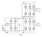
図1は、例示的な実施例に係る電池のエネルギー処理装置の構造ブロック図である。該電池のエネルギー処理装置は、第1インダクタL1と、第2インダクタL2と、第1相ブリッジアーム10と、第2相ブリッジアーム20と、エネルギー貯蔵素子30と、コントローラ40と、を含んでもよい。
Figure 1 is a structural block diagram of an energy processing device of a battery according to an exemplary embodiment. The energy processing device of the battery may include a first inductor L1, a second inductor L2, a first
第1インダクタL1の第1端子(左端)は、電池の正極(+)に接続され、第2インダクタL2の第1端子(左端)は、電池の正極に接続され、第1相ブリッジアーム10の中間点Aは、第1インダクタL1の第2端子(右端)に接続され、第2相ブリッジアーム20の中間点Bは、第2インダクタL2の第2端子(右端)に接続される。第1相ブリッジアーム10の第1端子10aと第2相ブリッジアーム20の第1端子20aは、共通接続されて第1バス端子を形成し、第1相ブリッジアーム10の第2端子10bと第2相ブリッジアーム20の第2端子20bは、共通接続されて第2バス端子を形成し、第2バス端子は、電池の負極(-)に接続される。
The first terminal (left end) of the first inductor L1 is connected to the positive pole (+) of the battery, the first terminal (left end) of the second inductor L2 is connected to the positive pole of the battery, the midpoint A of the first
エネルギー貯蔵素子30の第1端子(図1における上端)は、第1バス端子に接続され、エネルギー貯蔵素子30の第2端子(図1における下端)は、第2バス端子に接続される。 The first terminal of the energy storage element 30 (the upper end in FIG. 1) is connected to the first bus terminal, and the second terminal of the energy storage element 30 (the lower end in FIG. 1) is connected to the second bus terminal.
コントローラ40は、それぞれ第1相ブリッジアーム10と、第2相ブリッジアーム20に接続され、第1相ブリッジアーム10及び第2相ブリッジアーム20を制御することにより、電池が第1インダクタL1と第2インダクタL2により充電と放電を行って、電池への加熱を実現するように構成される。第1インダクタL1と第2インダクタL2は、異なる動作状態にある。
The controller 40 is connected to the first
図2は、例示的な実施例に係る電池のエネルギー処理装置における回路構造概略図である。図2に示すように、第1相ブリッジアーム10は、上ブリッジアームS1及び下ブリッジアームS2を含み、第2相ブリッジアーム20は、上ブリッジアームS3及び下ブリッジアームS4を含む。図2において、各ブリッジアームは、並列接続されたトランジスタ及びダイオードを例示的に含む。トランジスタは、さらに、他のスイッチトランジスタ、例えば、絶縁ゲートバイポーラトランジスタ(Insulated Gate Bipolar Transistor、IGBT)、金属-酸化物半導体電界効果トランジスタ(Metal-Oxide-Semiconductor Field-Effect Transistor、MOSFET)などで代替することができる。図2において、エネルギー貯蔵素子30は、例示的にキャパシタの形式で示され、さらにインダクタなどの他のタイプのエネルギー貯蔵素子であってもよい。
2 is a schematic diagram of a circuit structure in an energy processing device of a battery according to an exemplary embodiment. As shown in FIG. 2, the first
第1インダクタL1の第1端子L1aは、電池の正極(+)に接続され、第2インダクタL2の第1端子L2aは、電池の正極に接続され、第1相ブリッジアーム10の中間点Aは、第1インダクタL1の第2端子L1bに接続され、第2相ブリッジアーム20の中間点Bは、第2インダクタL2の第2端子L2bに接続される。第1相ブリッジアーム10の第1端子10aと第2相ブリッジアーム20の第1端子20aは、共通接続されて第1バス端子を形成し、第1相ブリッジアーム10の第2端子10bと第2相ブリッジアーム20の第2端子20bは、共通接続されて第2バス端子を形成し、第2バス端子は、電池の負極(-)に接続される。
The first terminal L1a of the first inductor L1 is connected to the positive pole (+) of the battery, the first terminal L2a of the second inductor L2 is connected to the positive pole of the battery, the midpoint A of the first
本解決手段において、第1インダクタL1と第2インダクタL2は、電池加熱の過程において、常に異なる動作状態にあり、実際に2つの異なるインダクタとして使用される。本解決手段における2つのインダクタを交互に(異なる動作状態)制御する方式は、一定の程度で互いに補い、互いに制約する作用を果たすことができ、回路におけるリップル電流が小さく、電磁両立性が高く、電池の発熱は、電池が充電又は放電を行う場合、電池を流れる電流により電池の内部抵抗を発熱させることによるものであり、電池が内から外へ昇温するため、電池の加熱効率が高い。 In this solution, the first inductor L1 and the second inductor L2 are always in different operating states during the battery heating process, and are actually used as two different inductors. The method of alternately controlling the two inductors (different operating states) in this solution allows them to complement and constrain each other to a certain extent, resulting in small ripple current in the circuit and high electromagnetic compatibility. When the battery is charging or discharging, the current flowing through the battery causes the internal resistance of the battery to heat up, and the battery heats up from the inside out, resulting in high battery heating efficiency.
図2に示す回路構造図では、電池加熱期間において、異なる電流の流れ方向による複数の段階を設定することができ、それに応じて、2つのインダクタの動作状態は、エネルギー貯蔵状態、フリーホイール状態及び非動作状態を含んでもよい。エネルギー貯蔵状態にある場合、インダクタ自体が充電を行い、インダクタ両端の電圧が大きくなり、フリーホイール状態にある場合、インダクタ自体が放電を行い、インダクタ両端の電圧が小さくなり、非動作状態にある場合、インダクタ自体が充電及び放電を行わず、インダクタ両端の電圧が変化しない。 In the circuit structure diagram shown in FIG. 2, multiple stages with different current flow directions can be set during the battery heating period, and the operating states of the two inductors may accordingly include an energy storage state, a freewheel state, and a non-operating state. In the energy storage state, the inductor itself charges, and the voltage across the inductor becomes large; in the freewheel state, the inductor itself discharges, and the voltage across the inductor becomes small; in the non-operating state, the inductor itself does not charge or discharge, and the voltage across the inductor does not change.
上記異なる動作状態に基づいて、具体的には、2つのインダクタをそれぞれエネルギー貯蔵、フリーホイール及び非動作の3種の状態のうちの2種の状態にさせ、好ましい状態の多様化は、設定可能な電流の流れ方向ポリシーを多様化させるだけでなく、試験の方式で様々なポリシーを比較し、リップル電流が相対的に小さく、より優れた電流の流れ方向ポリシーを選択することができる。 Based on the above different operating states, specifically, the two inductors are each put into two of the three states of energy storage, freewheeling, and non-operating. Diversifying the preferred states not only diversifies the configurable current flow direction policies, but also allows the comparison of various policies in a test manner to select a better current flow direction policy with a relatively small ripple current.
さらに別の実施例において、コントローラ40は、第1相ブリッジアーム10及び第2相ブリッジアーム20を制御することにより、電池とエネルギー貯蔵素子30が第1インダクタL1と第2インダクタL2により充電と放電を行って、電池への加熱を実現するように構成される。
In yet another embodiment, the controller 40 is configured to control the first
電池とエネルギー貯蔵素子30が充電と放電を行うことは、電池充電、エネルギー貯蔵素子30放電の過程、及び/又は、電池放電、エネルギー貯蔵素子30充電の過程を含んでもよい。
Charging and discharging the battery and
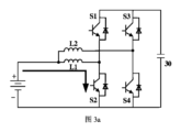
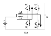
例えば、図3a~図3fは、それぞれ例示的な実施例に係る1つの電流周期における6つの段階の電流方向概略図である。該実施例の1つの電流周期において、コントローラは、それぞれ6つの段階で以下の6つのステップを実行するように第1相ブリッジアームと第2相ブリッジアームを制御してもよい。 For example, Figures 3a-3f are schematic diagrams of current directions for six stages in one current cycle according to an exemplary embodiment. In one current cycle of the embodiment, the controller may control the first phase bridge arm and the second phase bridge arm to perform the following six steps in each of the six stages:
ステップ1では、オンにするように第1相ブリッジアームの下ブリッジアームS2を制御し、オフにするように第1相ブリッジアームの上ブリッジアームS1、第2相ブリッジアームの上ブリッジアームS3及び下ブリッジアームS4を制御することにより、電池が第1インダクタL1に対して充電を行う。図3aに示すように、電流は、電池の正極から流出し、第1インダクタL1、第1相ブリッジアームの下ブリッジアームS2を流れて電池の負極に戻る。
In
ステップ2では、オンにするように第1相ブリッジアームの上ブリッジアームS1及び第2相ブリッジアームの下ブリッジアームS4を制御し、オフにするように第1相ブリッジアームの下ブリッジアームS2及び第2相ブリッジアームの上ブリッジアームS3を制御することにより、電池が第2インダクタL2に対して充電を行い、第1インダクタL1がエネルギー貯蔵素子30に対して充電を行う。図3bに示すように、電流は、電池の正極から流出し、一部が第1インダクタL1、第1相ブリッジアームの上ブリッジアームS1、エネルギー貯蔵素子30を流れて電池の負極に戻り、他の一部が第2インダクタL2、第2相ブリッジアームの下ブリッジアームS4を流れて電池の負極に戻る。
In
ステップ3では、オンにするように第2相ブリッジアームの上ブリッジアームS3を制御し、オフにするように第2相ブリッジアームの下ブリッジアームS4、第1相ブリッジアームの上ブリッジアームS1及び下ブリッジアームS2を制御することにより、第2インダクタL2がエネルギー貯蔵素子30に対して充電を行う。図3cに示すように、電流は、電池の正極から流出し、第2インダクタL2、第2相ブリッジアームの上ブリッジアームS3、エネルギー貯蔵素子30を流れて電池の負極に戻る。
In step 3, the second inductor L2 charges the
ステップ4では、オンにするように第2相ブリッジアームの上ブリッジアームS3を制御し、オフにするように第2相ブリッジアームの下ブリッジアームS4、第1相ブリッジアームの上ブリッジアームS1及び下ブリッジアームS2を制御することにより、エネルギー貯蔵素子30が第2インダクタL2により電池に対して充電を行う。図3dに示すように、電流は、電池の負極から流出し、エネルギー貯蔵素子30、第2相ブリッジアームの上ブリッジアームS3、第2インダクタL2を流れて電池の正極に戻る。
In
ステップ5では、オンにするように第1相ブリッジアームの上ブリッジアームS1及び第2相ブリッジアームの下ブリッジアームS4を制御し、オフにするように第1相ブリッジアームの下ブリッジアームS2及び第2相ブリッジアームの上ブリッジアームS3を制御することにより、エネルギー貯蔵素子30が第1インダクタL1により電池に対して充電を行い、第2インダクタL2が電池に対して充電を行う。図3eに示すように、電流は、電池の負極から流出し、一部がエネルギー貯蔵素子30、第1相ブリッジアームの上ブリッジアームS1、第1インダクタL1を流れて電池の正極に戻り、他の一部が第2相ブリッジアームの下ブリッジアームS4、第2インダクタL2を流れて電池の正極に戻る。
In step 5, the upper bridge arm S1 of the first phase bridge arm and the lower bridge arm S4 of the second phase bridge arm are controlled to be turned on, and the lower bridge arm S2 of the first phase bridge arm and the upper bridge arm S3 of the second phase bridge arm are controlled to be turned off, so that the
ステップ6では、オンにするように第1相ブリッジアームの下ブリッジアームS2を制御し、オフにするように第1相ブリッジアームの上ブリッジアームS1、第2相ブリッジアームの上ブリッジアームS3及び下ブリッジアームS4を制御することにより、第1インダクタL1が電池に対して充電を行う。図3fに示すように、電流は、電池の負極から流出し、第1相ブリッジアームの下ブリッジアームS2、第1インダクタL1を流れて電池の正極に戻る。 In step 6, the first inductor L1 charges the battery by controlling the lower bridge arm S2 of the first phase bridge arm to be turned on and the upper bridge arm S1 of the first phase bridge arm, the upper bridge arm S3 of the second phase bridge arm, and the lower bridge arm S4 to be turned off. As shown in FIG. 3f, current flows from the negative terminal of the battery, through the lower bridge arm S2 of the first phase bridge arm and the first inductor L1, and returns to the positive terminal of the battery.
該実施例において、上記第3段階から第4段階への切り替えは、ブリッジアームの動作を制御する必要がなく、エネルギー貯蔵素子30に対して充電を行った後にエネルギー貯蔵素子30が自動的に放電することにより、状態が切り替えられる。このように、電流周期には同じ数のステップを有する場合、コントローラの制御動作を減少させ、コントローラの制御フローを簡略化し、電池の加熱をより確実にする。
In this embodiment, the switching from the third stage to the fourth stage does not require control of the operation of the bridge arm, and the state is switched by automatically discharging the
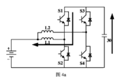
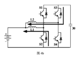
別の実施例において、コントローラも、それぞれ6つの段階で6つのステップを実行するように制御する。該実施例の1つの電流周期において、前の3つの段階は、前の実施例における前の3つの段階(図3a~図3c)と同じであってもよい。図4a~図4cは、それぞれ別の例示的な実施例に係る1つの電流周期における後の3つの段階の電流方向概略図である。 In another embodiment, the controller also controls to execute six steps with six stages each. In one current cycle of this embodiment, the first three stages may be the same as the first three stages in the previous embodiment (FIGS. 3a-3c). FIGS. 4a-4c are schematic diagrams of the current direction of the last three stages in one current cycle according to another exemplary embodiment.
第4段階において、オンにするように第1相ブリッジアームの上ブリッジアームS1を制御し、オフにするように第1相ブリッジアームの下ブリッジアームS2、第2相ブリッジアームの上ブリッジアームS3及び下ブリッジアームS4を制御することにより、エネルギー貯蔵素子30が第1インダクタL1により電池に対して充電を行う。図4aに示すように、電流は、電池の負極から流出し、エネルギー貯蔵素子30、第1相ブリッジアームの上ブリッジアームS1、第1インダクタL1を流れて電池の正極に戻る。
In the fourth stage, the upper bridge arm S1 of the first phase bridge arm is controlled to be turned on, and the lower bridge arm S2 of the first phase bridge arm, the upper bridge arm S3 of the second phase bridge arm, and the lower bridge arm S4 of the second phase bridge arm are controlled to be turned off, so that the
第5段階において、オンにするように第1相ブリッジアームの下ブリッジアームS2及び第2相ブリッジアームの上ブリッジアームS3を制御し、オフにするように第1相ブリッジアームの上ブリッジアームS1及び第2相ブリッジアームの下ブリッジアームS4を制御することにより、エネルギー貯蔵素子30が第2インダクタL2により電池に対して充電を行い、第1インダクタL1が電池に対して充電を行う。図4bに示すように、電流は、電池の負極から流出し、一部がエネルギー貯蔵素子30、第2相ブリッジアームの上ブリッジアームS3、第2インダクタL2を流れて電池の正極に戻り、他の一部が第1相ブリッジアームの下ブリッジアームS2、第1インダクタL1を流れて電池の正極に戻る。
In the fifth stage, the lower bridge arm S2 of the first phase bridge arm and the upper bridge arm S3 of the second phase bridge arm are controlled to be turned on, and the upper bridge arm S1 of the first phase bridge arm and the lower bridge arm S4 of the second phase bridge arm are controlled to be turned off, so that the
第6段階において、オンにするように第2相ブリッジアームの下ブリッジアームS4を制御し、オフにするように第2相ブリッジアームの上ブリッジアームS3、第1相ブリッジアームの上ブリッジアームS1及び下ブリッジアームS2を制御することにより、第2インダクタL2が電池に対して充電を行う。図4cに示すように、電流は、第2インダクタL2から流出し、電池、第2相ブリッジアームの下ブリッジアームS4を流れて第2インダクタL2に戻る。 In the sixth stage, the second inductor L2 charges the battery by controlling the lower bridge arm S4 of the second phase bridge arm to be turned on and the upper bridge arm S3 of the second phase bridge arm, the upper bridge arm S1 of the first phase bridge arm, and the lower bridge arm S2 of the first phase bridge arm to be turned off. As shown in FIG. 4c, the current flows out of the second inductor L2, through the battery, the lower bridge arm S4 of the second phase bridge arm, and back to the second inductor L2.
前の実施例(図3a~図3f)と比較し、該実施例(図3a~図3c、図4a~図4c)において、電流周期には同じ数のステップを有し、コントローラが各ステップを能動的に制御することにより、電位エネルギーが大きくなり、電池加熱の効率が高くなる。 Compared to the previous embodiment (Figs. 3a-3f), in this embodiment (Figs. 3a-3c, 4a-4c), the current cycle has the same number of steps, and the controller actively controls each step, resulting in a larger potential energy and more efficient battery heating.
本開示の解決手段において、第1インダクタと第2インダクタの状態は、いくつかの異なる組み合わせを有してもよい。図3a~図3c、図4a~図4cを1つの電流周期とする実施例を例とし、1つの電流周期における6つの段階は、3種の組み合わせを含んでもよい。 In the solution of the present disclosure, the states of the first inductor and the second inductor may have several different combinations. Taking the examples of Figs. 3a to 3c and 4a to 4c as one current cycle, the six stages in one current cycle may include three combinations.
第1種の組み合わせは、第1インダクタがエネルギー貯蔵状態にあり、第2インダクタが非動作状態にあり、図3a及び図4aの段階を含むことである。コントローラは、第1相ブリッジアーム及び第2相ブリッジアームを制御することにより、電池又はエネルギー貯蔵素子30が第1インダクタL1に放電して、電池への加熱を実現するように構成される。図3aの段階において、電池は、第1インダクタL1に放電し、図4aの段階において、エネルギー貯蔵素子30は、第1インダクタL1に放電する。
The first type of combination is that the first inductor is in an energy storage state and the second inductor is in a non-operating state, and includes the stages of Fig. 3a and Fig. 4a. The controller is configured to control the first phase bridge arm and the second phase bridge arm to cause the battery or
このような組み合わせにおいて、1つのインダクタのみを用いてエネルギーを貯蔵する。他のインダクタが動作しないため、一定の程度で電池を流れる電流が大きすぎないように制限することにより、発生した電流リップルが小さい。 In this type of combination, only one inductor is used to store energy. Since the other inductor is not in operation, the current flowing through the battery is limited to a certain extent so that it does not become too large, resulting in a small current ripple.
第2種の組み合わせは、第2インダクタがエネルギー貯蔵状態にあり、第1インダクタがフリーホイール状態にあり、図3b及び図4bの段階を含むことである。コントローラは、第1相ブリッジアーム及び第2相ブリッジアームを制御することにより、電池及びエネルギー貯蔵素子30のうちの一方が第2インダクタL2に放電し、他方が第1インダクタL1により充電を行って、電池への加熱を実現するように構成される。
The second type of combination is that the second inductor is in an energy storage state and the first inductor is in a freewheeling state, and includes the steps of Figures 3b and 4b. The controller is configured to control the first phase bridge arm and the second phase bridge arm so that one of the battery and the
図3bの段階において、電池は、第2インダクタL2に放電し、エネルギー貯蔵素子30は、第1インダクタL1により充電を行い、図4bの段階において、エネルギー貯蔵素子30は、第2インダクタL2に放電し、電池は、第1インダクタL1により充電を行う。
At the stage in FIG. 3b, the battery discharges to the second inductor L2 and the
このような組み合わせにおいて、1つのインダクタがエネルギーを貯蔵し、もう1つのインダクタがフリーホイーリングし、2つのインダクタが同時に動作するが、両者は、交互相補的な傾向があるため、大きな電流リップルの発生を回避するとともに、加熱効率を向上させる。 In such a combination, one inductor stores energy and the other freewheels, and the two inductors operate simultaneously, but tend to complement each other, thus avoiding large current ripples and improving heating efficiency.
第3種の組み合わせは、第2インダクタがフリーホイール状態にあり、第1インダクタが非動作状態にあり、図3c及び図4cの段階を含むことである。コントローラは、第1相ブリッジアーム及び第2相ブリッジアームを制御することにより、電池又はエネルギー貯蔵素子が第2インダクタにより充電を行って、電池への加熱を実現するように構成される。図3cの段階において、エネルギー貯蔵素子は、第2インダクタにより充電を行い、図4cの段階において、電池は、第2インダクタにより充電を行う。 The third combination is that the second inductor is in a freewheeling state and the first inductor is in a non-operating state, and includes the stages of Fig. 3c and Fig. 4c. The controller is configured to control the first phase bridge arm and the second phase bridge arm to make the battery or the energy storage element charge through the second inductor to realize heating of the battery. In the stage of Fig. 3c, the energy storage element charges through the second inductor, and in the stage of Fig. 4c, the battery charges through the second inductor.
このような組み合わせにおいて、1つのインダクタのみを用いてフリーホイーリングする。他のインダクタが動作しないため、一定の程度で電池を流れる電流が大きすぎないように制限することにより、発生した電流リップルが小さい。 In this type of combination, only one inductor is used for freewheeling. Since the other inductors are not in operation, the current flowing through the battery is limited to a certain extent so that it does not become too large, resulting in a small current ripple.
図2における回路構造は、電池加熱専用の回路として設置されてもよく、電池と同じ装置内にある関連デバイス内の回路を多重化してもよい。例えば、電池は、車載電池であり、第1インダクタ及び第2インダクタは、車両の電圧変換器におけるインダクタであり、第1相ブリッジアーム及び第2相ブリッジアームは、電圧変換器におけるブリッジアームであり、エネルギー貯蔵素子は、バスキャパシタである。電圧変換器は、昇圧直流(Direct Current、DC)モジュールであってもよい。また、例えば、電池は、車載電池であり、第1相ブリッジアーム及び第2相ブリッジアームは、車両のモータコントローラにおけるブリッジアームであり、エネルギー貯蔵素子は、バスキャパシタである。 The circuit structure in FIG. 2 may be installed as a circuit dedicated to battery heating, or may multiplex the circuit in an associated device in the same apparatus as the battery. For example, the battery is an on-board battery, the first and second inductors are inductors in a voltage converter of the vehicle, the first and second phase bridge arms are bridge arms in the voltage converter, and the energy storage element is a bus capacitor. The voltage converter may be a step-up direct current (DC) module. Also, for example, the battery is an on-board battery, the first and second phase bridge arms are bridge arms in a motor controller of the vehicle, and the energy storage element is a bus capacitor.
このように、類似する回路構造を有するデバイスについて、該デバイスが動作しない場合にその回路を多重化すると、ハードウェアの配置を節約し、回路接続を減少させ、かつ空間を節約し、デバイスの体積を増大させず、デバイスの小型化に役立ち、車両の従来の構造を変更せず、電池加熱を実現し、解決手段のコストが低い。 In this way, for devices with similar circuit structures, multiplexing the circuits when the devices are not working saves on hardware layout, reduces circuit connections, and saves space, does not increase the volume of the device, helps to miniaturize the device, does not change the existing structure of the vehicle, realizes battery heating, and has a low cost solution.
他のデバイスにおける回路を多重化すると、回路にスイッチモジュールを設置し、スイッチモジュールのオンオフを制御することにより、多重化回路の機能を切り替えるという目的を達成することができる。図5は、別の例示的な実施例に係る電池のエネルギー処理装置における回路構造概略図である。図5の実施例において、電池は、車載電池であり、多重化されたのは、車両のモータコントローラにおける回路であり、図2を基に、該電池のエネルギー処理装置は、第1スイッチモジュールK1、第2スイッチモジュールK2及び第3スイッチモジュールK3をさらに含んでもよい。 When a circuit in another device is multiplexed, a switch module is installed in the circuit, and the purpose of switching the function of the multiplexed circuit can be achieved by controlling the on/off of the switch module. Figure 5 is a schematic diagram of the circuit structure in a battery energy processing device according to another exemplary embodiment. In the embodiment of Figure 5, the battery is an on-board battery, and the multiplexed circuit is a circuit in a motor controller of the vehicle. Based on Figure 2, the battery energy processing device may further include a first switch module K1, a second switch module K2, and a third switch module K3.
第1スイッチモジュールK1の第1端子(図5におけるK1の左端)は、電池の正極に接続され、第1スイッチモジュールK1の第2端子(図5におけるK1の右端)は、エネルギー貯蔵素子30の第1端子(図5におけるエネルギー貯蔵素子30の上端)に接続される。
The first terminal of the first switch module K1 (the left end of K1 in FIG. 5) is connected to the positive electrode of the battery, and the second terminal of the first switch module K1 (the right end of K1 in FIG. 5) is connected to the first terminal of the energy storage element 30 (the upper end of the
第2スイッチモジュールK2の第1端子(図5におけるK2の左端)は、第1相ブリッジアーム10の中間点に接続され、第2スイッチモジュールK2の第2端子(図5におけるK2の右端)は、モータGの第1相巻線(図示せず)に接続される。
The first terminal of the second switch module K2 (the left end of K2 in FIG. 5) is connected to the midpoint of the first
第3スイッチモジュールK3の第1端子(図5におけるK3の左端)は、第2相ブリッジアーム20の中間点に接続され、第3スイッチモジュールK3の第2端子(図5におけるK3の右端)は、モータGの第2相巻線(図示せず)に接続される。
The first terminal of the third switch module K3 (the left end of K3 in FIG. 5) is connected to the midpoint of the second
該実施例において、コントローラは、オフにするように第1スイッチモジュールK1、第2スイッチモジュールK2及び第3スイッチモジュールK3を制御することにより、電池への加熱を実現するように構成される。K1、K2及びK3がオフになると、第1相ブリッジアーム10及び第2相ブリッジアーム20のモータへの制御をオフにし、電池加熱用に変換し、回路設計及び制御ポリシーは、いずれも簡単であり、電池加熱用の機能に迅速に変換することができ、信頼性が高い。
In this embodiment, the controller is configured to realize heating of the battery by controlling the first switch module K1, the second switch module K2, and the third switch module K3 to be turned off. When K1, K2, and K3 are turned off, the control of the first
図5に示すように、該装置は、第4スイッチモジュールK4をさらに含んでもよい。第4スイッチモジュールK4の第1端子(図5におけるK4の左端)は、電池の正極に接続され、第4スイッチモジュールK4の第2端子(図5におけるK4の右端)は、それぞれ第1インダクタL1の第1端子(図5におけるL1の左端)と第2インダクタL2の第1端子(図5におけるL2の左端)に接続される。 As shown in FIG. 5, the device may further include a fourth switch module K4. A first terminal of the fourth switch module K4 (the left end of K4 in FIG. 5) is connected to the positive electrode of the battery, and a second terminal of the fourth switch module K4 (the right end of K4 in FIG. 5) is connected to the first terminal of the first inductor L1 (the left end of L1 in FIG. 5) and the first terminal of the second inductor L2 (the left end of L2 in FIG. 5), respectively.
該実施例において、コントローラは、さらに、オフにするように第4スイッチモジュールK4を制御し、オンにするように第1スイッチモジュールK1、第2スイッチモジュールK2及び第3スイッチモジュールK3を制御することにより、電池のモータへの駆動を実現するように構成される。キャパシタCは、バスキャパシタである。図5から分かるように、K4がオフになり、K1、K2及びK3がオンになると、線路において第1インダクタL1及び第2インダクタL2がオフになり、3相ブリッジアームによりモータGへの制御を実現することができ、すなわち線路がモータコントローラとして機能するように変換され、該切り替え回路の設計及び制御ポリシーは、いずれも簡単であり、モータを駆動する機能に迅速に変換することができ、信頼性が高い。 In this embodiment, the controller is further configured to control the fourth switch module K4 to be turned off and the first switch module K1, the second switch module K2 and the third switch module K3 to be turned on, thereby realizing the driving of the battery to the motor. The capacitor C is a bus capacitor. As can be seen from FIG. 5, when K4 is turned off and K1, K2 and K3 are turned on, the first inductor L1 and the second inductor L2 are turned off in the line, and the control of the motor G can be realized by the three-phase bridge arm, that is, the line is converted to function as a motor controller, and the design and control policy of the switching circuit are both simple, can be quickly converted to the function of driving the motor, and is highly reliable.
上記実施例において、1つの電流周期におけるブリッジアーム動作、電流の流れ方向及び充放電状態を説明した。さらに別の実施例において、コントローラは、第1相ブリッジアーム及び第2相ブリッジアームを制御することにより、電池及びエネルギー貯蔵素子が第1インダクタ及び第2インダクタにより充電及び放電を繰り返し行って、電池への加熱を実現するように構成されてもよい。第1インダクタと第2インダクタは、異なる動作状態にある。すなわち、電池加熱を停止する条件に達するまで、上記電流周期を繰り返し実行してもよい。電池加熱を停止する条件は、例えば、電池温度が所定の温度閾値に達することであってもよい。 In the above embodiment, the bridge arm operation, current flow direction, and charge/discharge state in one current cycle have been described. In yet another embodiment, the controller may be configured to control the first phase bridge arm and the second phase bridge arm so that the battery and the energy storage element are repeatedly charged and discharged by the first inductor and the second inductor to realize heating of the battery. The first inductor and the second inductor are in different operating states. That is, the above current cycle may be repeatedly executed until a condition for stopping battery heating is reached. The condition for stopping battery heating may be, for example, the battery temperature reaching a predetermined temperature threshold.
該実施例において、所定のステップを繰り返し実行することにより、電池に対して充電を連続的に行うという目的を達成するとともに、制御ポリシーが簡単であり、誤りが発生しにくく、信頼性が高い。 In this embodiment, the purpose of continuously charging the battery is achieved by repeatedly executing certain steps, while the control policy is simple, errors are unlikely to occur, and reliability is high.
図6aは、例示的な実施例に係る1つのインダクタを利用して加熱する場合に回路における電流の経時変化の曲線図である。図6bは、例示的な実施例に係る本解決手段における2つのインダクタを利用して加熱する場合に回路における電流の経時変化の曲線図である。横座標は、時間であり、縦座標は、回路における電流であり、すなわち動力電池を流れる電流である。図6a及び図6bに示すように、1つのインダクタのみを用いて加熱する場合、曲線における電流のリップルが大きく、2つのインダクタを用いて加熱する場合、曲線における電流リップルは、単一のインダクタの場合に比べて明らかに減少する。これから分かるように、本開示の解決手段を利用して電池を加熱する時に、同じ電流を出力する場合に、回路におけるリップル電流が小さいため、電池のエネルギー処理装置の電磁両立性を顕著に向上させる。 Figure 6a is a curve diagram of the current change over time in the circuit when heating using one inductor according to an exemplary embodiment. Figure 6b is a curve diagram of the current change over time in the circuit when heating using two inductors in the solution according to an exemplary embodiment. The abscissa is time, and the ordinate is the current in the circuit, i.e., the current flowing through the power battery. As shown in Figures 6a and 6b, when heating using only one inductor, the current ripple in the curve is large, and when heating using two inductors, the current ripple in the curve is obviously reduced compared to the case of a single inductor. As can be seen, when using the solution of the present disclosure to heat a battery, when the same current is output, the ripple current in the circuit is small, which significantly improves the electromagnetic compatibility of the energy processing device of the battery.
本開示は、さらに、電池のエネルギー処理方法を提供する。図7は、例示的な実施例に係る電池のエネルギー処理方法のフローチャートである。図7に示すように、該方法は、電池を加熱する必要があると判定すると、第1相ブリッジアーム及び第2相ブリッジアームを制御することにより、電池が第1インダクタと第2インダクタにより充電と放電を行って、電池への加熱を実現するステップS71を含んでもよい。第1インダクタと第2インダクタは、異なる動作状態にある。 The present disclosure further provides a method for processing energy in a battery. FIG. 7 is a flowchart of a method for processing energy in a battery according to an exemplary embodiment. As shown in FIG. 7, the method may include a step S71 of, when it is determined that the battery needs to be heated, controlling a first phase bridge arm and a second phase bridge arm to cause the battery to charge and discharge through a first inductor and a second inductor, thereby achieving heating of the battery. The first inductor and the second inductor are in different operating states.
第1インダクタの第1端子は、電池の正極に接続され、第2インダクタの第1端子は、電池の正極に接続され、第1相ブリッジアームの中間点は、第1インダクタの第2端子に接続され、第2相ブリッジアームの中間点は、第2インダクタの第2端子に接続され、第1相ブリッジアームの第1端子と第2相ブリッジアームの第1端子は、共通接続されて第1バス端子を形成し、第1相ブリッジアームの第2端子と第2相ブリッジアームの第2端子は、共通接続されて第2バス端子を形成し、第2バス端子は、電池の負極に接続され、エネルギー貯蔵素子の第1端子は、第1バス端子に接続され、エネルギー貯蔵素子の第2端子は、第2バス端子に接続される。 The first terminal of the first inductor is connected to the positive electrode of the battery, the first terminal of the second inductor is connected to the positive electrode of the battery, the midpoint of the first phase bridge arm is connected to the second terminal of the first inductor, the midpoint of the second phase bridge arm is connected to the second terminal of the second inductor, the first terminal of the first phase bridge arm and the first terminal of the second phase bridge arm are commonly connected to form a first bus terminal, the second terminal of the first phase bridge arm and the second terminal of the second phase bridge arm are commonly connected to form a second bus terminal, the second bus terminal is connected to the negative electrode of the battery, the first terminal of the energy storage element is connected to the first bus terminal, and the second terminal of the energy storage element is connected to the second bus terminal.
本解決手段において、第1インダクタと第2インダクタは、電池加熱の過程において、常に異なる動作状態にあり、実際に2つの異なるインダクタとして使用される。1つのインダクタを用いるか又は同じ動作状態にある複数のインダクタを用いる電池加熱制御方式と比較し、本解決手段における2つのインダクタを交互に(異なる動作状態)制御する方式は、一定の程度で互いに補い、互いに制約する作用を果たすことができ、同じ電流を出力する場合に、回路におけるリップル電流が小さいことにより、電池のエネルギー処理装置の電磁両立性を顕著に向上させる。 In this solution, the first inductor and the second inductor are always in different operating states during the battery heating process, and are actually used as two different inductors. Compared with a battery heating control method using one inductor or multiple inductors in the same operating state, the method of alternately controlling the two inductors (different operating states) in this solution can complement and constrain each other to a certain extent, and when the same current is output, the ripple current in the circuit is small, which significantly improves the electromagnetic compatibility of the battery energy processing device.
好ましくは、2つのインダクタの動作状態は、エネルギー貯蔵状態、フリーホイール状態及び非動作状態を含んでもよい。電池を加熱する必要があると判定すると、第1相ブリッジアーム及び第2相ブリッジアームを制御することにより、電池が第1インダクタと第2インダクタにより充電と放電を行って、電池への加熱を実現するステップ(ステップS71)は、電池を加熱する必要があると判定すると、第1相ブリッジアーム及び第2相ブリッジアームを制御することにより、電池とエネルギー貯蔵素子が第1インダクタと第2インダクタにより充電と放電を行って、電池への加熱を実現するステップを含んでもよい。 Preferably, the operating states of the two inductors may include an energy storage state, a freewheel state, and a non-operating state. The step (step S71) of controlling the first phase bridge arm and the second phase bridge arm to charge and discharge the battery through the first inductor and the second inductor when it is determined that the battery needs to be heated may include controlling the first phase bridge arm and the second phase bridge arm to charge and discharge the battery and the energy storage element through the first inductor and the second inductor when it is determined that the battery needs to be heated.
上記異なる動作状態に基づいて、具体的には、2つのインダクタをそれぞれエネルギー貯蔵、フリーホイール及び非動作の3種の状態のうちの2種の状態にさせ、好ましい状態の多様化は、設定可能な電流の流れ方向ポリシーを多様化させるだけでなく、試験の方式で様々なポリシーを比較し、リップル電流が相対的に小さく、より優れた電流の流れ方向ポリシーを選択することができる。 Based on the above different operating states, specifically, the two inductors are each put into two of the three states of energy storage, freewheeling, and non-operating. Diversifying the preferred states not only diversifies the configurable current flow direction policies, but also allows the comparison of various policies in a test manner to select a better current flow direction policy with a relatively small ripple current.
好ましくは、第1相ブリッジアーム及び第2相ブリッジアームを制御することにより、電池とエネルギー貯蔵素子が第1インダクタと第2インダクタにより充電と放電を行って、電池への加熱を実現するステップは、第1相ブリッジアーム及び第2相ブリッジアームを制御することにより、電池又はエネルギー貯蔵素子が第1インダクタに放電して、電池への加熱を実現するステップであって、第1インダクタがエネルギー貯蔵状態にあり、第2インダクタが非動作状態にあるステップ、
又は、第1相ブリッジアーム及び第2相ブリッジアームを制御することにより、電池及びエネルギー貯蔵素子のうちの一方が第2インダクタに放電し、他方が第1インダクタにより充電を行って、電池への加熱を実現するステップであって、第2インダクタがエネルギー貯蔵状態にあり、第1インダクタがフリーホイール状態にあるステップ、
又は、第1相ブリッジアーム及び第2相ブリッジアームを制御することにより、電池又はエネルギー貯蔵素子が第2インダクタにより充電を行って、電池への加熱を実現するステップであって、第2インダクタがフリーホイール状態にあり、第1インダクタが非動作状態にあるステップを含んでもよい。
Preferably, the step of controlling the first phase bridge arm and the second phase bridge arm to cause the battery and the energy storage element to charge and discharge through the first inductor and the second inductor to realize heating of the battery includes the steps of controlling the first phase bridge arm and the second phase bridge arm to cause the battery or the energy storage element to discharge into the first inductor to realize heating of the battery, in which the first inductor is in an energy storage state and the second inductor is in a non-operating state;
or controlling the first phase bridge arm and the second phase bridge arm so that one of the battery and the energy storage element discharges to the second inductor and the other charges through the first inductor, thereby achieving heating of the battery, wherein the second inductor is in an energy storage state and the first inductor is in a freewheeling state;
Alternatively, the step may include controlling the first phase bridge arm and the second phase bridge arm so that the battery or energy storage element charges through the second inductor to achieve heating of the battery, wherein the second inductor is in a freewheeling state and the first inductor is in a non-operating state.
1つのインダクタが動作し、もう1つのインダクタが動作しない場合、一定の程度で電池を流れる電流が大きすぎないように制限することにより、発生した電流リップルが小さい。1つのインダクタがエネルギーを貯蔵し、もう1つのインダクタがフリーホイーリングする場合、2つのインダクタが同時に動作するが、両者は、交互相補的な傾向があるため、大きな電流リップルの発生を回避するとともに、加熱効率を向上させる。 When one inductor is working and the other is not, the current flowing through the battery is limited to a certain extent so that it is not too large, resulting in a small current ripple. When one inductor is storing energy and the other is freewheeling, the two inductors are working simultaneously, but they tend to complement each other, thus avoiding the generation of a large current ripple and improving heating efficiency.
好ましくは、第1相ブリッジアーム及び第2相ブリッジアームを制御することにより、電池とエネルギー貯蔵素子が第1インダクタと第2インダクタにより充電と放電を行うステップは、
オンにするように第1相ブリッジアームの下ブリッジアームを制御し、オフにするように第1相ブリッジアームの上ブリッジアーム、第2相ブリッジアームの上ブリッジアーム及び下ブリッジアームを制御することにより、電池が第1インダクタに対して充電を行うステップ1と、
オンにするように第1相ブリッジアームの上ブリッジアーム及び第2相ブリッジアームの下ブリッジアームを制御し、オフにするように第1相ブリッジアームの下ブリッジアーム及び第2相ブリッジアームの上ブリッジアームを制御することにより、電池が第2インダクタに対して充電を行い、第1インダクタがエネルギー貯蔵素子に対して充電を行うステップ2と、
オンにするように第2相ブリッジアームの上ブリッジアームを制御し、オフにするように第2相ブリッジアームの下ブリッジアーム、第1相ブリッジアームの上ブリッジアーム及び下ブリッジアームを制御することにより、第2インダクタがエネルギー貯蔵素子に対して充電を行うステップ3と、
オンにするように第2相ブリッジアームの上ブリッジアームを制御し、オフにするように第2相ブリッジアームの下ブリッジアーム、第1相ブリッジアームの上ブリッジアーム及び下ブリッジアームを制御することにより、エネルギー貯蔵素子が第2インダクタにより電池に対して充電を行うステップ4と、
オンにするように第1相ブリッジアームの上ブリッジアーム及び第2相ブリッジアームの下ブリッジアームを制御し、オフにするように第1相ブリッジアームの下ブリッジアーム及び第2相ブリッジアームの上ブリッジアームを制御することにより、エネルギー貯蔵素子が第1インダクタにより電池に対して充電を行い、第2インダクタが電池に対して充電を行うステップ5と、
オンにするように第1相ブリッジアームの下ブリッジアームを制御し、オフにするように第1相ブリッジアームの上ブリッジアーム、第2相ブリッジアームの上ブリッジアーム及び下ブリッジアームを制御することにより、第1インダクタが電池に対して充電を行うステップ6と、を含んでもよい。
Preferably, the step of controlling the first phase bridge arm and the second phase bridge arm to charge and discharge the battery and the energy storage element through the first inductor and the second inductor comprises:
Step 2: controlling the upper bridge arm of the first phase bridge arm and the lower bridge arm of the second phase bridge arm to be turned on and controlling the lower bridge arm of the first phase bridge arm and the upper bridge arm of the second phase bridge arm to be turned off, so that the battery charges the second inductor and the first inductor charges the energy storage element;
Step 3: controlling the upper bridge arm of the second phase bridge arm to be turned on, and controlling the lower bridge arm of the second phase bridge arm, the upper bridge arm and the lower bridge arm of the first phase bridge arm to be turned off, so that the second inductor charges the energy storage element;
Step 4: controlling the upper bridge arm of the second phase bridge arm to be turned on, and controlling the lower bridge arm of the second phase bridge arm, the upper bridge arm and the lower bridge arm of the first phase bridge arm to be turned off, so that the energy storage element charges the battery through the second inductor;
Step 5: controlling the upper bridge arm of the first phase bridge arm and the lower bridge arm of the second phase bridge arm to be turned on and controlling the lower bridge arm of the first phase bridge arm and the upper bridge arm of the second phase bridge arm to be turned off, so that the energy storage element charges the battery through the first inductor and the second inductor charges the battery;
and step 6, in which the first inductor charges the battery by controlling the lower bridge arm of the first phase bridge arm to be turned on and controlling the upper bridge arm of the first phase bridge arm and the upper bridge arm and the lower bridge arm of the second phase bridge arm to be turned off.
該実施例において、上記第3段階から第4段階への切り替えは、ブリッジアームの動作を制御する必要がなく、エネルギー貯蔵素子30に対して充電を行った後にエネルギー貯蔵素子30が自動的に放電することにより、状態が切り替えられる。このように、電流周期には同じ数のステップを有する場合、コントローラの制御動作を減少させ、コントローラの制御フローを簡略化し、電池の加熱をより確実にする。
In this embodiment, the switching from the third stage to the fourth stage does not require control of the operation of the bridge arm, and the state is switched by automatically discharging the
好ましくは、第1相ブリッジアーム及び第2相ブリッジアームを制御することにより、電池とエネルギー貯蔵素子が第1インダクタと第2インダクタにより充電と放電を行うステップは、
オンにするように第1相ブリッジアームの下ブリッジアームを制御し、オフにするように第1相ブリッジアームの上ブリッジアーム、第2相ブリッジアームの上ブリッジアーム及び下ブリッジアームを制御することにより、電池が第1インダクタに対して充電を行うステップ1と、
オンにするように第1相ブリッジアームの上ブリッジアーム及び第2相ブリッジアームの下ブリッジアームを制御し、オフにするように第1相ブリッジアームの下ブリッジアーム及び第2相ブリッジアームの上ブリッジアームを制御することにより、電池が第2インダクタに対して充電を行い、第1インダクタがエネルギー貯蔵素子に対して充電を行うステップ2と、
オンにするように第2相ブリッジアームの上ブリッジアームを制御し、オフにするように第2相ブリッジアームの下ブリッジアーム、第1相ブリッジアームの上ブリッジアーム及び下ブリッジアームを制御することにより、第2インダクタがエネルギー貯蔵素子に対して充電を行うステップ3と、
オンにするように第1相ブリッジアームの上ブリッジアームを制御し、オフにするように第1相ブリッジアームの下ブリッジアーム、第2相ブリッジアームの上ブリッジアーム及び下ブリッジアームを制御することにより、エネルギー貯蔵素子が第1インダクタにより電池に対して充電を行うステップ4と、
オンにするように第1相ブリッジアームの下ブリッジアーム及び第2相ブリッジアームの上ブリッジアームを制御し、オフにするように第1相ブリッジアームの上ブリッジアーム及び第2相ブリッジアームの下ブリッジアームを制御することにより、エネルギー貯蔵素子が第2インダクタにより電池に対して充電を行い、第1インダクタが電池に対して充電を行うステップ5と、
オンにするように第2相ブリッジアームの下ブリッジアームを制御し、オフにするように第2相ブリッジアームの上ブリッジアーム、第1相ブリッジアームの上ブリッジアーム及び下ブリッジアームを制御することにより、第2インダクタが電池に対して充電を行うステップ6と、を含んでもよい。
Preferably, the step of controlling the first phase bridge arm and the second phase bridge arm to charge and discharge the battery and the energy storage element through the first inductor and the second inductor comprises:
Step 2: controlling the upper bridge arm of the first phase bridge arm and the lower bridge arm of the second phase bridge arm to be turned on and controlling the lower bridge arm of the first phase bridge arm and the upper bridge arm of the second phase bridge arm to be turned off, so that the battery charges the second inductor and the first inductor charges the energy storage element;
Step 3: controlling the upper bridge arm of the second phase bridge arm to be turned on, and controlling the lower bridge arm of the second phase bridge arm, the upper bridge arm and the lower bridge arm of the first phase bridge arm to be turned off, so that the second inductor charges the energy storage element;
Step 4: controlling the upper bridge arm of the first phase bridge arm to be turned on, and controlling the lower bridge arm of the first phase bridge arm, and the upper bridge arm and the lower bridge arm of the second phase bridge arm to be turned off, so that the energy storage element charges the battery through the first inductor;
Step 5: controlling the lower bridge arm of the first phase bridge arm and the upper bridge arm of the second phase bridge arm to be turned on and controlling the upper bridge arm of the first phase bridge arm and the lower bridge arm of the second phase bridge arm to be turned off, so that the energy storage element charges the battery through the second inductor and the first inductor charges the battery;
and step 6, in which the second inductor charges the battery by controlling the lower bridge arm of the second phase bridge arm to be on and controlling the upper bridge arm of the second phase bridge arm and the upper bridge arm and the lower bridge arm of the first phase bridge arm to be off.
該実施例において、コントローラが各ステップを能動的に制御することにより、電位エネルギーが大きくなり、電池加熱の効率が高くなる。 In this embodiment, the controller actively controls each step, increasing the potential energy and improving the efficiency of battery heating.
上記実施例における方法について、各ステップが操作を実行する具体的な方式は、該装置に関連する実施例において詳細に説明されており、ここで詳細に説明しない。 The specific manner in which each step performs an operation in the method in the above embodiment is described in detail in the embodiment related to the device, and will not be described in detail here.
さらに別の実施例において、第1インダクタと第2インダクタのうちの一方がエネルギー貯蔵状態にあり、他方がフリーホイール状態にある段階において、動作するようにインダクタのフリーホイールを行うブリッジアームを制御した後、所定の時間を遅延して、動作するようにインダクタのエネルギー貯蔵を行うブリッジアームを制御する。 In yet another embodiment, when one of the first inductor and the second inductor is in an energy storage state and the other is in a freewheeling state, a bridge arm that freewheels the inductor is controlled to operate, and then, after a predetermined time delay, the bridge arm that stores energy in the inductor is controlled to operate.
所定の時間は、ブリッジアームにおけるスイッチトランジスタのスイッチング周期に基づいて設定されてもよく、例えば、所定の時間は、ブリッジアームにおけるスイッチトランジスタの半周期であってもよい。 The predetermined time may be set based on the switching period of the switch transistor in the bridge arm, for example, the predetermined time may be a half period of the switch transistor in the bridge arm.
例えば、図3bの段階において、オフにするように第1インダクタL1のフリーホイールを行う第1相ブリッジアームの下ブリッジアームS2を制御し、オンにするように第2インダクタL2のエネルギー貯蔵を行う第2相ブリッジアームの下ブリッジアームS4を制御する必要がある。まず、オフにするように第1相ブリッジアームの下ブリッジアームS2を制御し、オフにした後、ブリッジアームスイッチトランジスタの半周期を経過し、次に、オンにするように第2相ブリッジアームの下ブリッジアームS4を制御する。 For example, in the stage of FIG. 3b, it is necessary to control the lower bridge arm S2 of the first phase bridge arm, which performs freewheeling of the first inductor L1, to be turned off, and control the lower bridge arm S4 of the second phase bridge arm, which performs energy storage of the second inductor L2, to be turned on. First, the lower bridge arm S2 of the first phase bridge arm is controlled to be turned off, and after it is turned off, a half period of the bridge arm switch transistor passes, and then the lower bridge arm S4 of the second phase bridge arm is controlled to be turned on.
また、例えば、図3eの段階において、オンにするように第1インダクタL1のエネルギー貯蔵を行う第1相ブリッジアームの上ブリッジアームS1を制御し、オフにするように第2インダクタL2のフリーホイールを行う第2相ブリッジアームの上ブリッジアームS3を制御する必要がある。まず、オフにするように第2相ブリッジアームの上ブリッジアームS3を制御し、オフにした後、ブリッジアームスイッチトランジスタの半周期を経過し、次に、オンにするように第1相ブリッジアームの上ブリッジアームS1を制御する。 Also, for example, in the stage of FIG. 3e, it is necessary to control the upper bridge arm S1 of the first phase bridge arm that stores the energy of the first inductor L1 to be turned on, and control the upper bridge arm S3 of the second phase bridge arm that freewheels the second inductor L2 to be turned off. First, the upper bridge arm S3 of the second phase bridge arm is controlled to be turned off, and after it is turned off, a half-cycle of the bridge arm switch transistor passes, and then the upper bridge arm S1 of the first phase bridge arm is controlled to be turned on.
上記遅延操作により、ブリッジアームを交互にオンオフにすることにより、インダクタがフリーホイールを一定の時間開始した後、もう1つのインダクタがエネルギー貯蔵を開始し、このように電流衝撃を低減することができ、電荷がゆっくりと移動することができ、これは、インダクタ自体の充放電特性に合致し、装置の耐用年数を延長することに役立つ。 The above delay operation allows the bridge arms to be alternately turned on and off, so that after one inductor starts freewheeling for a certain period of time, the other inductor starts storing energy, thus reducing the current impulse and allowing the charge to move more slowly, which matches the charging and discharging characteristics of the inductor itself and helps to extend the service life of the device.
さらに別の実施例において、加熱期間において、第1相ブリッジアーム及び第2相ブリッジアームにおけるスイッチング周波数又はデューティ比を調整することにより、電池を流れる電流値が最適な電流値に達してもよい。 In yet another embodiment, during the heating period, the current value flowing through the battery may reach an optimal current value by adjusting the switching frequency or duty ratio of the first and second phase bridge arms.
最適な電流値は、電池及び回路特性を総合的に考慮する、電池を流れる理想的な電流値である。第1相ブリッジアームと第2相ブリッジアームが電圧変換器におけるブリッジアームであれば、最適な電流値は、電池に許容される最大電流値と電圧変換器に許容される最大電流値の両者のうちの小さい値であってもよい。 The optimal current value is the ideal current value flowing through the battery, taking into consideration the battery and circuit characteristics as a whole. If the first phase bridge arm and the second phase bridge arm are bridge arms in a voltage converter, the optimal current value may be the smaller of the maximum current value allowable for the battery and the maximum current value allowable for the voltage converter.
電池に許容される最大電流値は、電池SOC、温度、交番周波数、電圧、単一の周期での充放電容量などの要因に関連する。電圧変換器に許可された最大電流値は、主にIGBTモジュールチップのジャンクション温度、インダクタコイルセンサの温度に制限され、メッセージにより収集された現在のIGBTチップの温度と、インダクタコイルセンサにより収集された現在の温度と、IGBTチップ及びインダクタコイルセンサのトルク制限温度とに基づいて、ルックアップテーブルの方式により電圧変換器に許可された最大電流を得ることができる。 The maximum current value allowed for the battery is related to factors such as the battery SOC, temperature, alternating frequency, voltage, and charge/discharge capacity in a single cycle. The maximum current value allowed for the voltage converter is mainly limited by the junction temperature of the IGBT module chip and the temperature of the inductor coil sensor, and the maximum current allowed for the voltage converter can be obtained by a lookup table method based on the current IGBT chip temperature collected by the message, the current temperature collected by the inductor coil sensor, and the torque limit temperature of the IGBT chip and the inductor coil sensor.
具体的には、最適な電流値は、以下の式により得ることができる。 Specifically, the optimal current value can be obtained by the following formula:
I(f)=min(I_max1,I_max2)
I_max1=C*f
I_max2=(U_max-OCV)/(R_ac(f))
ここで、I(f)は、最適な電流値であり、I_max1は、電池に許容される最大電流値であり、I_max2は、電圧変換器に許容される最大電流値であり、minは、最小値を求めることであり、Cは、1つのサイクルにおけるパルス充放電が超えてはならない容量であり、fは、電池の交番周波数であり、U_maxは、電池の最大電圧であり、OCVは、開放電圧であり、R_ac(f)は、電池の交流内部抵抗がfに伴って変化する関数である。
I(f)=min(I_max1, I_max2)
I_max1=C*f
I_max2=(U_max-OCV)/(R_ac(f))
where I(f) is the optimum current value, I_max1 is the maximum current value allowed for the battery, I_max2 is the maximum current value allowed for the voltage converter, and min is the minimum The object is to obtain the value, where C is the capacity that the pulse charge/discharge in one cycle must not exceed, f is the alternating frequency of the battery, U_max is the maximum voltage of the battery, and OCV is the open circuit voltage. where f is the voltage and R_ac(f) is a function of the battery's AC internal resistance that varies with f.
該実施例において、第1相ブリッジアーム及び第2相ブリッジアームにおけるスイッチング周波数又はデューティ比を調整することにより、電池を流れる電流値が最適な電流値に達することは、簡単な方法を利用することにより、電池加熱の効率が徐々に最大化に達し、制御しやすくかつ信頼性が高い。 In this embodiment, by adjusting the switching frequency or duty ratio in the first phase bridge arm and the second phase bridge arm, the current value flowing through the battery reaches an optimal current value, and by using a simple method, the efficiency of battery heating gradually reaches its maximum, which is easy to control and highly reliable.
さらに別の実施例において、加熱期間において、第1相ブリッジアーム及び第2相ブリッジアームのデューティ比を調整することにより、電池を流れる電流値が最適な電流値に達するステップは、
加熱期間において、電池を流れる電流と最適な電流値との比較結果及び第1相ブリッジアームと第2相ブリッジアームの現在のキャリア周波数周期におけるデューティ比に基づいて、第1相ブリッジアーム及び第2相ブリッジアームの次のキャリア周波数周期におけるデューティ比を調整することにより、電池を流れる電流値が最適な電流値に達するステップを含んでもよい。
In yet another embodiment, the step of adjusting the duty ratio of the first phase bridge arm and the second phase bridge arm during the heating period so that the current value flowing through the battery reaches an optimal current value includes:
The heating period may include a step of adjusting the duty ratios of the first phase bridge arm and the second phase bridge arm in the next carrier frequency cycle based on a comparison result between the current flowing through the battery and an optimal current value and the duty ratios of the first phase bridge arm and the second phase bridge arm in the current carrier frequency cycle, so that the current value flowing through the battery reaches an optimal current value.
すなわち、第1相ブリッジアームと第2相ブリッジアームの各キャリア周波数周期におけるデューティ比は、いずれも前のキャリア周波数周期におけるデューティ比の状況に応じて調整されて、最適なデューティ比(最適な電流値に対応)に徐々に達する。このように、デューティ比調整の頻度が高いことにより、最適なデューティ比及び最適な電流値に迅速に達することができ、電池加熱の効率を迅速に向上させる。 In other words, the duty ratios of the first and second phase bridge arms in each carrier frequency cycle are adjusted according to the duty ratio conditions in the previous carrier frequency cycle, gradually reaching the optimal duty ratio (corresponding to the optimal current value). In this way, by adjusting the duty ratio frequently, the optimal duty ratio and optimal current value can be quickly reached, and the efficiency of battery heating is quickly improved.
さらに別の実施例において、加熱期間において、電池を流れる電流と最適な電流値との比較結果及び第1相ブリッジアームと第2相ブリッジアームの現在のキャリア周波数周期におけるデューティ比に基づいて、第1相ブリッジアーム及び第2相ブリッジアームの次のキャリア周波数周期におけるデューティ比を調整することにより、電池を流れる電流値が最適な電流値に達するステップは、
電池の充電又は放電期間において、電池を流れる電流が最適な電流値より小さい場合、現在のキャリア周波数周期におけるデューティ比より大きいように第1相ブリッジアーム及び第2相ブリッジアームの次のキャリア周波数周期におけるデューティ比を制御するステップと、電池を流れる電流が最適な電流値より大きい場合、電池を流れる電流値が最適な電流値に達するまで、現在のキャリア周波数周期におけるデューティ比より小さいように第1相ブリッジアーム及び第2相ブリッジアームの次のキャリア周波数周期におけるデューティ比を制御するステップと、を含んでもよい。
In yet another embodiment, the step of adjusting the duty ratio of the first phase bridge arm and the second phase bridge arm in the next carrier frequency period based on a comparison result between the current flowing through the battery and the optimal current value and the duty ratio of the first phase bridge arm and the second phase bridge arm in the current carrier frequency period so that the current flowing through the battery reaches the optimal current value during the heating period includes:
The method may include a step of controlling the duty ratio of the first phase bridge arm and the second phase bridge arm in the next carrier frequency cycle so that it is larger than the duty ratio in the current carrier frequency cycle when the current flowing through the battery is smaller than an optimal current value during charging or discharging of the battery, and a step of controlling the duty ratio of the first phase bridge arm and the second phase bridge arm in the next carrier frequency cycle so that it is smaller than the duty ratio in the current carrier frequency cycle when the current flowing through the battery is larger than the optimal current value, until the current value flowing through the battery reaches the optimal current value.
すなわち、デューティ比の閉ループ制御により、回路における電流を、最終的に最適な電流値にする(又は加熱停止条件を満たすため、最適な電流値に達する前に加熱を停止する)。具体的には、初期のデューティ比を予め決定し、デューティ比調整のステップサイズを予め決定し、デューティ比の閉ループ制御過程において、初期のデューティ比及びステップサイズを利用して次のキャリア周波数周期におけるデューティ比を調整してもよい。このように、電池のエネルギー処理装置の安全を保証するだけでなく、加熱効率を向上させ、加熱時間を短縮することができる。 That is, the current in the circuit is finally brought to an optimal current value by closed-loop control of the duty ratio (or heating is stopped before reaching the optimal current value in order to satisfy the heating stop condition). Specifically, the initial duty ratio may be predetermined, and the step size for adjusting the duty ratio may be predetermined, and the duty ratio in the next carrier frequency period may be adjusted using the initial duty ratio and the step size during the closed-loop control process of the duty ratio. In this way, not only is the safety of the battery's energy processing device ensured, but the heating efficiency can be improved and the heating time can be shortened.
図8は、例示的な実施例に係る電池のエネルギー処理方法のフローチャートである。図8に示すように、電池自己加熱前に、電池管理システムは、電池温度Tを収集してもよく、温度Tが設定された温度値Tminより小さいと、電池SOCを収集し、収集されたSOCが設定されたSOCminより大きいと判定すると、加熱を開始する。又は、収集されたSOC<SOCminである場合、加熱しない。サンプリング温度T及びサンプリングSOCが、同時に要件、すなわちT<Tmin、かつサンプリングSOC>SOCminを満たす場合のみ、電池自己加熱プログラムを起動することができる。例えば、Tminは、零下10℃であってもよく、SOCminは、10%であってもよい。また、セル間の最大温度差を考慮すると、収集された電池温度は、複数の監視点の平均値であってもよい。 FIG. 8 is a flow chart of a battery energy processing method according to an exemplary embodiment. As shown in FIG. 8, before the battery self-heating, the battery management system may collect the battery temperature T, and if the temperature T is less than a set temperature value Tmin, collect the battery SOC, and start heating when it determines that the collected SOC is greater than the set SOCmin. Or, if the collected SOC<SOCmin, do not heat. Only when the sampling temperature T and the sampling SOC simultaneously meet the requirements, i.e., T<Tmin and the sampling SOC>SOCmin, can the battery self-heating program be activated. For example, Tmin may be minus 10° C., and SOCmin may be 10%. In addition, considering the maximum temperature difference between cells, the collected battery temperature may be an average value of multiple monitoring points.
電池自己加熱プログラムを起動した後、電流の流れ方向を先に判定してもよい。電池がエネルギー貯蔵素子に対して充電を行うと、電流が0より大きく、S2、S4を制御して電池の放電を制御し、エネルギー貯蔵素子が電池に対して充電を行うと、電池の電流が0より小さく、S1、S3を制御して充電する電流を制御する。 After starting the battery self-heating program, the direction of current flow may be determined first. When the battery charges the energy storage element, the current is greater than 0, and S2 and S4 are controlled to control the discharge of the battery. When the energy storage element charges the battery, the battery current is less than 0, and S1 and S3 are controlled to control the charging current.
加熱プログラムを起動した後、電圧変換器のIGBTスイッチング周波数及び電池の交番キャリア周波数が決定された場合、初期のデューティ比をD0に設定する。電流が0より大きい場合、電池は、エネルギー貯蔵素子に対して充電を行い、オンにするようにS2を制御し、デューティ比がD0であり、半周期遅延した後、オンにするようにS4を制御し、デューティ比がD0である。同時に、この時の回路上の現在の電流値を収集し、現在の電流値が最適な電流値より小さい場合、次のキャリア周波数周期において、S2をオンにし、デューティ比がD0+ΔTであり、半周期遅延した後、S4をオンにし、デューティ比がD0+ΔTである。現在の電流値が最適な電流値より大きい場合、次のキャリア周波数周期において、オンにするようにS2を制御し、デューティ比がD0-ΔTであり、半周期遅延した後、オンにするようにS4を制御し、デューティ比がD0-ΔTである。デューティ比を調整した後、電池温度Tを再収集し、電池温度Tが設定された温度値Tminに達するか否かを判定する必要がある。電池の電流が0より小さい場合、S1と、S3を制御する方法は、類似する。 After starting the heating program, when the IGBT switching frequency of the voltage converter and the alternating carrier frequency of the battery are determined, set the initial duty ratio to D0. If the current is greater than 0, the battery charges the energy storage element, controls S2 to turn on, and the duty ratio is D0, and after a half-cycle delay, controls S4 to turn on, and the duty ratio is D0. At the same time, collect the current value on the circuit at this time, and if the current current value is less than the optimal current value, in the next carrier frequency period, control S2 to turn on, and the duty ratio is D0+ΔT, and after a half-cycle delay, control S4 to turn on, and the duty ratio is D0+ΔT. If the current current value is greater than the optimal current value, in the next carrier frequency period, control S2 to turn on, and the duty ratio is D0-ΔT, and after a half-cycle delay, control S4 to turn on, and the duty ratio is D0-ΔT. After adjusting the duty ratio, it is necessary to recollect the battery temperature T and determine whether the battery temperature T reaches the set temperature value Tmin. When the battery current is less than 0, the methods for controlling S1 and S3 are similar.
本開示は、車両をさらに提供する。図9は、例示的な実施例に係る車両の構造ブロック図である。図9に示すように、該車両は、電池100と、本開示に係る上記電池のエネルギー処理装置200とを含んでもよい。
The present disclosure further provides a vehicle. FIG. 9 is a structural block diagram of a vehicle according to an exemplary embodiment. As shown in FIG. 9, the vehicle may include a
図10は、別の例示的な実施例に係る車両の構造ブロック図である。該実施例において、車両は、ハイブリッド車両である。図10に示すように、該車両は、電池100、電圧変換器300、バスキャパシタ30、駆動モータG1、駆動モータ制御ブリッジアーム400、発電機G2、及び発電機制御ブリッジアーム500を含んでもよい。上記電池のエネルギー処理装置200は、電圧変換器300及びバスキャパシタ30を含む。電圧変換器300は、第1インダクタL1と、第2インダクタL2と、2相ブリッジアームとを含む。電圧変換器300における2相ブリッジアームの第1バス端子も駆動モータ制御ブリッジアーム400と発電機制御ブリッジアーム500の第1バス端子であり、電圧変換器300における2相ブリッジアームの第2バス端子も駆動モータ制御ブリッジアーム400と発電機制御ブリッジアーム500の第2バス端子である。
Figure 10 is a structural block diagram of a vehicle according to another exemplary embodiment. In this embodiment, the vehicle is a hybrid vehicle. As shown in Figure 10, the vehicle may include a
以上、図面を参照しながら、本開示の好ましい実施形態を詳細に説明したが、本開示は、上記実施形態における具体的な内容に限定されるものではなく、本開示の技術的概念の範囲内に、本開示の技術手段に対して複数の簡単な変更を行うことができ、これらの簡単な変更は、いずれも本開示の保護範囲内にある。 Although preferred embodiments of the present disclosure have been described in detail above with reference to the drawings, the present disclosure is not limited to the specific contents of the above embodiments, and multiple simple modifications can be made to the technical means of the present disclosure within the scope of the technical concept of the present disclosure, and all of these simple modifications fall within the scope of protection of the present disclosure.
なお、上記具体的な実施形態に説明された各具体的な技術的特徴は、矛盾しない場合に、任意の適当な方式で組み合わせることができる。不要な重複を回避するために、本開示は、可能なあらゆる組み合わせ方式を別途に説明しない。 Note that the specific technical features described in the above specific embodiments may be combined in any suitable manner, provided that there is no contradiction. In order to avoid unnecessary duplication, this disclosure does not separately describe all possible combination methods.
また、本開示の様々な実施形態は、任意に組み合わせることができ、本開示の構想から逸脱しない限り、本開示に開示されている内容と見なすべきである。 Furthermore, the various embodiments of the present disclosure may be combined in any manner and should be considered as disclosed in the present disclosure as long as such combination does not deviate from the concept of the present disclosure.
Claims (17)
第1端子が前記電池の正極に接続された第1インダクタと、
第1端子が前記電池の正極に接続された第2インダクタと、
中間点が前記第1インダクタの第2端子に接続された第1相ブリッジアームと、
中間点が前記第2インダクタの第2端子に接続された第2相ブリッジアームであって、前記第1相ブリッジアームの第1端子と前記第2相ブリッジアームの第1端子が共通接続されて第1バス端子を形成し、前記第1相ブリッジアームの第2端子と前記第2相ブリッジアームの第2端子が共通接続されて第2バス端子を形成し、前記第2バス端子が前記電池の負極に接続される、第2相ブリッジアームと、
第1端子が前記第1バス端子に接続され、第2端子が前記第2バス端子に接続されたエネルギー貯蔵素子と、
第1端子が前記電池の正極に接続され、第2端子が前記エネルギー貯蔵素子の第1端子に接続された第1スイッチモジュールと、
第1端子が前記第1相ブリッジアームの中間点に接続され、第2端子がモータの第1相巻線に接続された第2スイッチモジュールと、
第1端子が前記第2相ブリッジアームの中間点に接続され、第2端子が前記モータの第2相巻線に接続された第3スイッチモジュールと、
前記第1相ブリッジアーム及び前記第2相ブリッジアームを制御することにより、前記電池に前記第1インダクタと前記第2インダクタにより充電と放電を行って、前記電池への加熱を実現するように構成されたコントローラであって、前記第1インダクタ及び前記第2インダクタが異なる動作状態にある、コントローラと、を含み、
前記電池は、車載電池であり、前記第1相ブリッジアーム及び前記第2相ブリッジアームは、車両のモータコントローラにおけるブリッジアームであり、前記エネルギー貯蔵素子は、バスキャパシタであり、
前記コントローラは、オフにするように前記第1スイッチモジュール、前記第2スイッチモジュール及び前記第3スイッチモジュールを制御することにより、前記電池への加熱を実現するように構成されることを特徴とする、電池のエネルギー処理装置。 1. An energy processing device for a battery, comprising:
a first inductor having a first terminal connected to the positive terminal of the battery;
a second inductor having a first terminal connected to the positive terminal of the battery;
a first phase bridge arm having a midpoint connected to the second terminal of the first inductor;
a second phase bridge arm having a midpoint connected to a second terminal of the second inductor, a first terminal of the first phase bridge arm and a first terminal of the second phase bridge arm being commonly connected to form a first bus terminal, a second terminal of the first phase bridge arm and a second terminal of the second phase bridge arm being commonly connected to form a second bus terminal, and the second bus terminal being connected to a negative electrode of the battery;
an energy storage element having a first terminal connected to the first bus terminal and a second terminal connected to the second bus terminal;
a first switch module having a first terminal connected to the positive electrode of the battery and a second terminal connected to a first terminal of the energy storage element;
a second switch module having a first terminal connected to a midpoint of the first phase bridge arm and a second terminal connected to a first phase winding of a motor;
a third switch module having a first terminal connected to a midpoint of the second phase bridge arm and a second terminal connected to a second phase winding of the motor;
a controller configured to control the first phase bridge arm and the second phase bridge arm to charge and discharge the battery through the first inductor and the second inductor to realize heating of the battery, wherein the first inductor and the second inductor are in different operating states;
The battery is an on-board battery, the first phase bridge arm and the second phase bridge arm are bridge arms in a motor controller of a vehicle, and the energy storage element is a bus capacitor;
The energy treatment device of the battery, characterized in that the controller is configured to realize heating to the battery by controlling the first switch module, the second switch module and the third switch module to be turned off .
前記コントローラは、さらに、オフにするように前記第4スイッチモジュールを制御し、オンにするように前記第1スイッチモジュール、前記第2スイッチモジュール及び前記第3スイッチモジュールを制御することにより、前記電池の前記モータへの駆動を実現するように構成されることを特徴とする、請求項1に記載の装置。 a fourth switch module having a first terminal connected to the positive electrode of the battery and a second terminal connected to the first terminal of the first inductor and the first terminal of the second inductor, respectively;
2. The apparatus of claim 1, wherein the controller is further configured to realize power to the motor from the battery by controlling the fourth switch module to be off and controlling the first switch module, the second switch module, and the third switch module to be on.
電池を加熱する必要があると判定すると、第1相ブリッジアーム及び第2相ブリッジアームを制御することにより、前記電池を第1インダクタと第2インダクタにより充電と放電を行って、前記電池への加熱を実現するステップであって、前記第1インダクタと前記第2インダクタが異なる動作状態にあり、
前記第1インダクタの第1端子が前記電池の正極に接続され、前記第2インダクタの第1端子が前記電池の正極に接続され、前記第1相ブリッジアームの中間点が前記第1インダクタの第2端子に接続され、前記第2相ブリッジアームの中間点が前記第2インダクタの第2端子に接続され、前記第1相ブリッジアームの第1端子と前記第2相ブリッジアームの第1端子が共通接続されて第1バス端子を形成し、前記第1相ブリッジアームの第2端子と前記第2相ブリッジアームの第2端子が共通接続されて第2バス端子を形成し、前記第2バス端子が前記電池の負極に接続され、エネルギー貯蔵素子の第1端子が前記第1バス端子に接続され、前記エネルギー貯蔵素子の第2端子が前記第2バス端子に接続される、ステップを含み、
第1相ブリッジアーム及び第2相ブリッジアームを制御することにより、前記電池とエネルギー貯蔵素子を第1インダクタと第2インダクタにより充電と放電を行うステップは、
オンにするように前記第1相ブリッジアームの下ブリッジアームを制御し、オフにするように前記第1相ブリッジアームの上ブリッジアーム、前記第2相ブリッジアームの上ブリッジアーム及び下ブリッジアームを制御することにより、前記電池から前記第1インダクタに対して充電を行うステップと、
オンにするように前記第1相ブリッジアームの上ブリッジアーム及び前記第2相ブリッジアームの下ブリッジアームを制御し、オフにするように前記第1相ブリッジアームの下ブリッジアーム及び前記第2相ブリッジアームの上ブリッジアームを制御することにより、前記電池が前記第2インダクタに対して充電を行い、前記第1インダクタが前記エネルギー貯蔵素子に対して充電を行うステップと、
オンにするように前記第2相ブリッジアームの上ブリッジアームを制御し、オフにするように前記第2相ブリッジアームの下ブリッジアーム、前記第1相ブリッジアームの上ブリッジアーム及び下ブリッジアームを制御することにより、前記第2インダクタが前記エネルギー貯蔵素子に対して充電を行うステップと、
オンにするように前記第2相ブリッジアームの上ブリッジアームを制御し、オフにするように前記第2相ブリッジアームの下ブリッジアーム、前記第1相ブリッジアームの上ブリッジアーム及び下ブリッジアームを制御することにより、前記エネルギー貯蔵素子が前記第2インダクタにより前記電池に対して充電を行うステップと、
オンにするように前記第1相ブリッジアームの上ブリッジアーム及び前記第2相ブリッジアームの下ブリッジアームを制御し、オフにするように前記第1相ブリッジアームの下ブリッジアーム及び前記第2相ブリッジアームの上ブリッジアームを制御することにより、前記エネルギー貯蔵素子が前記第1インダクタにより前記電池に対して充電を行い、前記第2インダクタが前記電池に対して充電を行うステップと、
オンにするように前記第1相ブリッジアームの下ブリッジアームを制御し、オフにするように前記第1相ブリッジアームの上ブリッジアーム、前記第2相ブリッジアームの上ブリッジアーム及び下ブリッジアームを制御することにより、前記第1インダクタが前記電池に対して充電を行うステップと、を含むことを特徴とする、電池のエネルギー処理方法。 A method for processing energy in a battery, comprising:
When it is determined that the battery needs to be heated, the first phase bridge arm and the second phase bridge arm are controlled to charge and discharge the battery through a first inductor and a second inductor, thereby achieving heating of the battery, wherein the first inductor and the second inductor are in different operating states;
a first terminal of the first inductor is connected to a positive electrode of the battery, a first terminal of the second inductor is connected to a positive electrode of the battery, a midpoint of the first phase bridge arm is connected to a second terminal of the first inductor, a midpoint of the second phase bridge arm is connected to a second terminal of the second inductor, the first terminal of the first phase bridge arm and the first terminal of the second phase bridge arm are connected in common to form a first bus terminal, the second terminal of the first phase bridge arm and the second terminal of the second phase bridge arm are connected in common to form a second bus terminal, the second bus terminal is connected to a negative electrode of the battery , a first terminal of an energy storage element is connected to the first bus terminal, and the second terminal of the energy storage element is connected to the second bus terminal ,
Charging and discharging the battery and the energy storage element through a first inductor and a second inductor by controlling a first phase bridge arm and a second phase bridge arm,
charging the first inductor from the battery by controlling a lower bridge arm of the first phase bridge arm to be turned on and controlling an upper bridge arm of the first phase bridge arm and an upper bridge arm and a lower bridge arm of the second phase bridge arm to be turned off;
controlling an upper bridge arm of the first phase bridge arm and a lower bridge arm of the second phase bridge arm to be turned on and controlling a lower bridge arm of the first phase bridge arm and an upper bridge arm of the second phase bridge arm to be turned off, so that the battery charges the second inductor and the first inductor charges the energy storage element;
controlling an upper bridge arm of the second phase bridge arm to be turned on and controlling a lower bridge arm of the second phase bridge arm, and the upper bridge arm and the lower bridge arm of the first phase bridge arm to be turned off, so that the second inductor charges the energy storage element;
controlling an upper bridge arm of the second phase bridge arm to be turned on and controlling a lower bridge arm of the second phase bridge arm, and an upper bridge arm and a lower bridge arm of the first phase bridge arm to be turned off, so that the energy storage element charges the battery through the second inductor;
controlling an upper bridge arm of the first phase bridge arm and a lower bridge arm of the second phase bridge arm to be turned on and controlling a lower bridge arm of the first phase bridge arm and an upper bridge arm of the second phase bridge arm to be turned off, so that the energy storage element charges the battery through the first inductor and the second inductor charges the battery;
and controlling the lower bridge arm of the first phase bridge arm to be turned on and the upper bridge arm of the first phase bridge arm and the upper bridge arm and the lower bridge arm of the second phase bridge arm to be turned off, thereby causing the first inductor to charge the battery .
前記電池を加熱する必要があると判定すると、第1相ブリッジアーム及び第2相ブリッジアームを制御することにより、前記電池が第1インダクタと第2インダクタにより充電と放電を行って、前記電池への加熱を実現するステップは、前記電池を加熱する必要があると判定すると、第1相ブリッジアーム及び第2相ブリッジアームを制御することにより、前記電池と前記エネルギー貯蔵素子を第1インダクタと第2インダクタにより充電と放電を行って、前記電池への加熱を実現するステップを含むことを特徴とする、請求項9に記載の方法。 the operating states include an energy storage state, a freewheel state, and a non-operating state;
10. The method of claim 9, wherein when it is determined that the battery needs to be heated, the step of controlling a first phase bridge arm and a second phase bridge arm to cause the battery to be charged and discharged through a first inductor and a second inductor to realize heating of the battery includes the step of controlling a first phase bridge arm and a second phase bridge arm to cause the battery and the energy storage element to be charged and discharged through a first inductor and a second inductor to realize heating of the battery when it is determined that the battery needs to be heated .
前記第1相ブリッジアーム及び前記第2相ブリッジアームを制御することにより、前記電池又は前記エネルギー貯蔵素子から前記第1インダクタに放電して、前記電池への加熱を実現するステップであって、前記第1インダクタがエネルギー貯蔵状態にあり、前記第2インダクタが非動作状態にあるステップ、
又は、
前記第1相ブリッジアーム及び前記第2相ブリッジアームを制御することにより、前記電池及び前記エネルギー貯蔵素子のうちの一方から前記第2インダクタに放電し、他方を前記第1インダクタにより充電を行って、前記電池への加熱を実現するステップであって、前記第2インダクタがエネルギー貯蔵状態にあり、前記第1インダクタがフリーホイール状態にあるステップ、
又は、
前記第1相ブリッジアーム及び前記第2相ブリッジアームを制御することにより、前記電池又は前記エネルギー貯蔵素子を前記第2インダクタにより充電を行って、前記電池への加熱を実現するステップであって、前記第2インダクタがフリーホイール状態にあり、前記第1インダクタが非動作状態にあるステップを含むことを特徴とする、請求項10に記載の方法。 The step of controlling a first phase bridge arm and a second phase bridge arm to charge and discharge the battery and the energy storage element through a first inductor and a second inductor to realize heating of the battery includes:
A step of discharging the battery or the energy storage element to the first inductor by controlling the first phase bridge arm and the second phase bridge arm to realize heating of the battery, wherein the first inductor is in an energy storage state and the second inductor is in a non-operating state;
Or,
A step of controlling the first phase bridge arm and the second phase bridge arm to discharge one of the battery and the energy storage element to the second inductor and charge the other by the first inductor to realize heating of the battery, wherein the second inductor is in an energy storage state and the first inductor is in a freewheeling state;
Or,
11. The method of claim 10, further comprising the step of: charging the battery or the energy storage element through the second inductor by controlling the first phase bridge arm and the second phase bridge arm, where the second inductor is in a freewheeling state and the first inductor is in a non - operating state.
電池を加熱する必要があると判定すると、第1相ブリッジアーム及び第2相ブリッジアームを制御することにより、前記電池を第1インダクタと第2インダクタにより充電と放電を行って、前記電池への加熱を実現するステップであって、前記第1インダクタと前記第2インダクタが異なる動作状態にあり、
前記第1インダクタの第1端子が前記電池の正極に接続され、前記第2インダクタの第1端子が前記電池の正極に接続され、前記第1相ブリッジアームの中間点が前記第1インダクタの第2端子に接続され、前記第2相ブリッジアームの中間点が前記第2インダクタの第2端子に接続され、前記第1相ブリッジアームの第1端子と前記第2相ブリッジアームの第1端子が共通接続されて第1バス端子を形成し、前記第1相ブリッジアームの第2端子と前記第2相ブリッジアームの第2端子が共通接続されて第2バス端子を形成し、前記第2バス端子が前記電池の負極に接続され、エネルギー貯蔵素子の第1端子が前記第1バス端子に接続され、前記エネルギー貯蔵素子の第2端子が前記第2バス端子に接続される、ステップを含み、
第1相ブリッジアーム及び第2相ブリッジアームを制御することにより、前記電池とエネルギー貯蔵素子を第1インダクタと第2インダクタにより充電と放電を行うステップは、
オンにするように前記第1相ブリッジアームの下ブリッジアームを制御し、オフにするように前記第1相ブリッジアームの上ブリッジアーム、前記第2相ブリッジアームの上ブリッジアーム及び下ブリッジアームを制御することにより、前記電池が前記第1インダクタに対して充電を行うステップと、
オンにするように前記第1相ブリッジアームの上ブリッジアーム及び前記第2相ブリッジアームの下ブリッジアームを制御し、オフにするように前記第1相ブリッジアームの下ブリッジアーム及び前記第2相ブリッジアームの上ブリッジアームを制御することにより、前記電池が前記第2インダクタに対して充電を行い、前記第1インダクタが前記エネルギー貯蔵素子に対して充電を行うステップと、
オンにするように前記第2相ブリッジアームの上ブリッジアームを制御し、オフにするように前記第2相ブリッジアームの下ブリッジアーム、前記第1相ブリッジアームの上ブリッジアーム及び下ブリッジアームを制御することにより、前記第2インダクタが前記エネルギー貯蔵素子に対して充電を行うステップと、
オンにするように前記第1相ブリッジアームの上ブリッジアームを制御し、オフにするように前記第1相ブリッジアームの下ブリッジアーム、前記第2相ブリッジアームの上ブリッジアーム及び下ブリッジアームを制御することにより、前記エネルギー貯蔵素子が前記第1インダクタにより前記電池に対して充電を行うステップと、
オンにするように前記第1相ブリッジアームの下ブリッジアーム及び前記第2相ブリッジアームの上ブリッジアームを制御し、オフにするように前記第1相ブリッジアームの上ブリッジアーム及び前記第2相ブリッジアームの下ブリッジアームを制御することにより、前記エネルギー貯蔵素子が前記第2インダクタにより前記電池に対して充電を行い、前記第1インダクタが前記電池に対して充電を行うステップと、
オンにするように前記第2相ブリッジアームの下ブリッジアームを制御し、オフにするように前記第2相ブリッジアームの上ブリッジアーム、前記第1相ブリッジアームの上ブリッジアーム及び下ブリッジアームを制御することにより、前記第2インダクタが前記電池に対して充電を行うステップと、を含むことを特徴とする、電池のエネルギー処理方法。 A method for processing energy in a battery, comprising:
When it is determined that the battery needs to be heated, the first phase bridge arm and the second phase bridge arm are controlled to charge and discharge the battery through a first inductor and a second inductor, thereby achieving heating of the battery, wherein the first inductor and the second inductor are in different operating states;
a first terminal of the first inductor is connected to a positive electrode of the battery, a first terminal of the second inductor is connected to a positive electrode of the battery, a midpoint of the first phase bridge arm is connected to a second terminal of the first inductor, a midpoint of the second phase bridge arm is connected to a second terminal of the second inductor, the first terminal of the first phase bridge arm and the first terminal of the second phase bridge arm are connected in common to form a first bus terminal, the second terminal of the first phase bridge arm and the second terminal of the second phase bridge arm are connected in common to form a second bus terminal, the second bus terminal is connected to a negative electrode of the battery, a first terminal of an energy storage element is connected to the first bus terminal, and the second terminal of the energy storage element is connected to the second bus terminal,
Charging and discharging the battery and the energy storage element through a first inductor and a second inductor by controlling a first phase bridge arm and a second phase bridge arm,
controlling a lower bridge arm of the first phase bridge arm to be turned on and controlling an upper bridge arm of the first phase bridge arm, and an upper bridge arm and a lower bridge arm of the second phase bridge arm to be turned off, so that the battery charges the first inductor;
controlling an upper bridge arm of the first phase bridge arm and a lower bridge arm of the second phase bridge arm to be turned on and controlling a lower bridge arm of the first phase bridge arm and an upper bridge arm of the second phase bridge arm to be turned off, so that the battery charges the second inductor and the first inductor charges the energy storage element;
controlling an upper bridge arm of the second phase bridge arm to be turned on and controlling a lower bridge arm of the second phase bridge arm, and the upper bridge arm and the lower bridge arm of the first phase bridge arm to be turned off, so that the second inductor charges the energy storage element;
controlling an upper bridge arm of the first phase bridge arm to be turned on and controlling a lower bridge arm of the first phase bridge arm and an upper bridge arm and a lower bridge arm of the second phase bridge arm to be turned off, so that the energy storage element charges the battery through the first inductor;
controlling the lower bridge arm of the first phase bridge arm and the upper bridge arm of the second phase bridge arm to be turned on and controlling the upper bridge arm of the first phase bridge arm and the lower bridge arm of the second phase bridge arm to be turned off, so that the energy storage element charges the battery through the second inductor and the first inductor charges the battery;
and controlling the lower bridge arm of the second phase bridge arm to be turned on and the upper bridge arm of the second phase bridge arm and the upper bridge arm and the lower bridge arm of the first phase bridge arm to be turned off, thereby causing the second inductor to charge the battery .
電池を加熱する必要があると判定すると、第1相ブリッジアーム及び第2相ブリッジアームを制御することにより、前記電池を第1インダクタと第2インダクタにより充電と放電を行って、前記電池への加熱を実現するステップであって、前記第1インダクタと前記第2インダクタが異なる動作状態にあり、
前記第1インダクタの第1端子が前記電池の正極に接続され、前記第2インダクタの第1端子が前記電池の正極に接続され、前記第1相ブリッジアームの中間点が前記第1インダクタの第2端子に接続され、前記第2相ブリッジアームの中間点が前記第2インダクタの第2端子に接続され、前記第1相ブリッジアームの第1端子と前記第2相ブリッジアームの第1端子が共通接続されて第1バス端子を形成し、前記第1相ブリッジアームの第2端子と前記第2相ブリッジアームの第2端子が共通接続されて第2バス端子を形成し、前記第2バス端子が前記電池の負極に接続され、エネルギー貯蔵素子の第1端子が前記第1バス端子に接続され、前記エネルギー貯蔵素子の第2端子が前記第2バス端子に接続される、ステップを含み、
前記動作状態は、エネルギー貯蔵状態、フリーホイール状態及び非動作状態を含み、
前記電池を加熱する必要があると判定すると、第1相ブリッジアーム及び第2相ブリッジアームを制御することにより、前記電池が第1インダクタと第2インダクタにより充電と放電を行って、前記電池への加熱を実現するステップは、前記電池を加熱する必要があると判定すると、第1相ブリッジアーム及び第2相ブリッジアームを制御することにより、前記電池と前記エネルギー貯蔵素子を第1インダクタと第2インダクタにより充電と放電を行って、前記電池への加熱を実現するステップを含み、
前記第1インダクタと前記第2インダクタのうちの一方がエネルギー貯蔵状態にあり、他方がフリーホイール状態にある段階において、動作するようにインダクタのフリーホイールを行うブリッジアームを制御した後、所定の時間を遅延して、動作するようにインダクタのエネルギー貯蔵を行うブリッジアームを制御することを特徴とする、電池のエネルギー処理方法。 A method for processing energy in a battery, comprising:
When it is determined that the battery needs to be heated, the first phase bridge arm and the second phase bridge arm are controlled to charge and discharge the battery through a first inductor and a second inductor, thereby achieving heating of the battery, wherein the first inductor and the second inductor are in different operating states;
a first terminal of the first inductor is connected to a positive electrode of the battery, a first terminal of the second inductor is connected to a positive electrode of the battery, a midpoint of the first phase bridge arm is connected to a second terminal of the first inductor, a midpoint of the second phase bridge arm is connected to a second terminal of the second inductor, the first terminal of the first phase bridge arm and the first terminal of the second phase bridge arm are connected in common to form a first bus terminal, the second terminal of the first phase bridge arm and the second terminal of the second phase bridge arm are connected in common to form a second bus terminal, the second bus terminal is connected to a negative electrode of the battery, a first terminal of an energy storage element is connected to the first bus terminal, and the second terminal of the energy storage element is connected to the second bus terminal,
the operating states include an energy storage state, a freewheel state, and a non-operating state;
the step of controlling a first phase bridge arm and a second phase bridge arm when it is determined that the battery needs to be heated, thereby causing the battery to be charged and discharged through a first inductor and a second inductor, thereby realizing heating of the battery, includes the step of controlling a first phase bridge arm and a second phase bridge arm when it is determined that the battery needs to be heated, thereby causing the battery and the energy storage element to be charged and discharged through a first inductor and a second inductor, thereby realizing heating of the battery;
A battery energy processing method, characterized in that, when one of the first inductor and the second inductor is in an energy storage state and the other is in a freewheeling state, a bridge arm that performs freewheeling of the inductor is controlled to operate, and then, after a predetermined time delay, the bridge arm that performs energy storage of the inductor is controlled to operate.
前記加熱期間において、前記電池を流れる電流と前記最適な電流値との比較結果及び前記第1相ブリッジアームと前記第2相ブリッジアームの現在のキャリア周波数周期におけるデューティ比に基づいて、前記第1相ブリッジアーム及び前記第2相ブリッジアームの次のキャリア周波数周期におけるデューティ比を調整することにより、前記電池を流れる電流値が前記最適な電流値に達するステップを含むことを特徴とする、請求項14に記載の方法。 The step of adjusting the duty ratio of the first phase bridge arm and the second phase bridge arm during the heating period so that the current value flowing through the battery reaches an optimal current value,
15. The method according to claim 14, further comprising the step of: adjusting, during the heating period, the duty ratios of the first phase bridge arm and the second phase bridge arm in the next carrier frequency period based on a comparison result between the current flowing through the battery and the optimal current value and the duty ratios of the first phase bridge arm and the second phase bridge arm in the current carrier frequency period, so that the current value flowing through the battery reaches the optimal current value.
前記電池の充電又は放電期間において、前記電池を流れる電流が前記最適な電流値より小さい場合、現在のキャリア周波数周期におけるデューティ比より大きいように前記第1相ブリッジアーム及び前記第2相ブリッジアームの次のキャリア周波数周期におけるデューティ比を制御するステップと、前記電池を流れる電流が前記最適な電流値より大きい場合、前記電池を流れる電流値が前記最適な電流値に達するまで、現在のキャリア周波数周期におけるデューティ比より小さいように前記第1相ブリッジアーム及び前記第2相ブリッジアームの次のキャリア周波数周期におけるデューティ比を制御することを特徴とする、請求項15に記載の方法。 a step of adjusting the duty ratios of the first phase bridge arm and the second phase bridge arm in a next carrier frequency period based on a comparison result between the current flowing through the battery and the optimal current value and the duty ratios of the first phase bridge arm and the second phase bridge arm in a current carrier frequency period so that the current value flowing through the battery reaches the optimal current value during the heating period,
16. The method of claim 15, further comprising the steps of: controlling the duty ratios of the first phase bridge arm and the second phase bridge arm in the next carrier frequency period so as to be greater than the duty ratio in the current carrier frequency period when the current flowing through the battery is smaller than the optimal current value during the charging or discharging period of the battery; and controlling the duty ratios of the first phase bridge arm and the second phase bridge arm in the next carrier frequency period so as to be smaller than the duty ratio in the current carrier frequency period when the current flowing through the battery is greater than the optimal current value, until the current value flowing through the battery reaches the optimal current value.
Applications Claiming Priority (3)
| Application Number | Priority Date | Filing Date | Title |
|---|---|---|---|
| CN202010476447.1A CN113733987B (en) | 2020-05-29 | 2020-05-29 | Battery energy processing device and method, vehicle |
| CN202010476447.1 | 2020-05-29 | ||
| PCT/CN2020/130178 WO2021238103A1 (en) | 2020-05-29 | 2020-11-19 | Battery energy processing device and method, and vehicle |
Publications (2)
| Publication Number | Publication Date |
|---|---|
| JP2023527451A JP2023527451A (en) | 2023-06-28 |
| JP7518924B2 true JP7518924B2 (en) | 2024-07-18 |
Family
ID=78724733
Family Applications (1)
| Application Number | Title | Priority Date | Filing Date |
|---|---|---|---|
| JP2022573424A Active JP7518924B2 (en) | 2020-05-29 | 2020-11-19 | Battery energy processing device and method, and vehicle |
Country Status (7)
| Country | Link |
|---|---|
| US (1) | US20230238591A1 (en) |
| EP (1) | EP4159533A4 (en) |
| JP (1) | JP7518924B2 (en) |
| CN (1) | CN113733987B (en) |
| BR (1) | BR112022024118A2 (en) |
| CA (1) | CA3180352A1 (en) |
| WO (1) | WO2021238103A1 (en) |
Families Citing this family (9)
| Publication number | Priority date | Publication date | Assignee | Title |
|---|---|---|---|---|
| EP4308945A4 (en) * | 2021-03-18 | 2025-04-09 | Iontra Inc | Systems and methods for controlled battery heating sourcing current to and from the battery and discharge signal |
| CN116080422A (en) * | 2022-02-17 | 2023-05-09 | 华为电动技术有限公司 | Power battery pack device, heating control system and electric automobile |
| CN114572061B (en) * | 2022-03-17 | 2023-06-02 | 上海小至科技有限公司 | Vehicle motor system with battery preheating function and control method |
| CN114725544B (en) * | 2022-03-28 | 2024-09-17 | 华为数字能源技术有限公司 | Battery management system and battery system |
| CN117360329A (en) * | 2022-06-30 | 2024-01-09 | 比亚迪股份有限公司 | Battery self-heating device and method and electric vehicle |
| EP4557558A4 (en) * | 2022-09-22 | 2025-09-10 | Contemporary Amperex Technology Hong Kong Ltd | ADAPTATION METHOD FOR A BATTERY ADAPTING CIRCUIT, CONTROL METHOD FOR A BATTERY, AND MONITORING METHOD FOR A BATTERY |
| CN115556637B (en) * | 2022-11-08 | 2024-11-12 | 小米汽车科技有限公司 | Battery self-heating method, system, vehicle and storage medium |
| CN118082619A (en) * | 2022-11-25 | 2024-05-28 | 比亚迪股份有限公司 | Energy processing device and vehicle |
| CN116154362B (en) * | 2023-02-20 | 2024-10-22 | 吉林大学 | Current reversing high-frequency pulse self-heating device for power battery of new energy automobile |
Citations (6)
| Publication number | Priority date | Publication date | Assignee | Title |
|---|---|---|---|---|
| JP2008060047A (en) | 2006-09-04 | 2008-03-13 | Toyota Motor Corp | Power supply system and vehicle equipped with it, and temperature elevation control method of power storage device, as well as recording medium readable by computer recording program in order to carry out temperature elevation control of power storage device |
| JP2013187919A (en) | 2012-03-05 | 2013-09-19 | Nippon Soken Inc | Power converter |
| US20140286071A1 (en) | 2013-03-20 | 2014-09-25 | Samsung Sdi Co., Ltd. | Power conversion device having battery heating function |
| JP2018093608A (en) | 2016-12-01 | 2018-06-14 | 日産自動車株式会社 | Electric vehicle charging system and in-vehicle charging unit |
| JP2019071711A (en) | 2017-10-06 | 2019-05-09 | トヨタ自動車株式会社 | Power supply device |
| JP2020080620A (en) | 2018-11-13 | 2020-05-28 | トヨタ自動車株式会社 | Bidirectional power converter, electric automobile, and method for controlling bidirectional power converter |
Family Cites Families (11)
| Publication number | Priority date | Publication date | Assignee | Title |
|---|---|---|---|---|
| JPH09233709A (en) * | 1996-02-29 | 1997-09-05 | Denso Corp | Electric vehicle charger |
| JP5617473B2 (en) * | 2010-09-21 | 2014-11-05 | 株式会社デンソー | Battery heating device |
| KR101688485B1 (en) * | 2013-02-28 | 2016-12-21 | 삼성에스디아이 주식회사 | Energy storage apparatus |
| CN105762434B (en) * | 2016-05-16 | 2018-12-07 | 北京理工大学 | A kind of power-supply system and vehicle with self heating function |
| CN106787738A (en) * | 2017-03-14 | 2017-05-31 | 华中科技大学 | A kind of multiphase interleaving DC converter |
| CN108312878B (en) * | 2018-02-09 | 2020-11-13 | 合肥巨一动力系统有限公司 | Vehicle-mounted multiplexing charger |
| CN110723005B (en) * | 2018-06-29 | 2021-09-03 | 比亚迪股份有限公司 | Vehicle-mounted charger of electric vehicle, control method of vehicle-mounted charger and electric vehicle |
| CN110971173B (en) * | 2018-12-21 | 2021-01-19 | 比亚迪股份有限公司 | Charging method of power battery, motor control circuit and vehicle |
| CN110962631B (en) * | 2018-12-29 | 2020-11-17 | 宁德时代新能源科技股份有限公司 | Battery heating system and control method thereof |
| CN110970965B (en) * | 2019-06-24 | 2020-11-06 | 宁德时代新能源科技股份有限公司 | Switch control device and method, motor controller and battery pack heating control system |
| CN210468040U (en) * | 2019-09-06 | 2020-05-05 | 上海伊控动力系统有限公司 | Self-heating system for vehicle-mounted battery pack of electric vehicle |
-
2020
- 2020-05-29 CN CN202010476447.1A patent/CN113733987B/en active Active
- 2020-11-19 WO PCT/CN2020/130178 patent/WO2021238103A1/en not_active Ceased
- 2020-11-19 CA CA3180352A patent/CA3180352A1/en active Pending
- 2020-11-19 US US17/928,560 patent/US20230238591A1/en active Pending
- 2020-11-19 BR BR112022024118A patent/BR112022024118A2/en unknown
- 2020-11-19 JP JP2022573424A patent/JP7518924B2/en active Active
- 2020-11-19 EP EP20937691.2A patent/EP4159533A4/en active Pending
Patent Citations (6)
| Publication number | Priority date | Publication date | Assignee | Title |
|---|---|---|---|---|
| JP2008060047A (en) | 2006-09-04 | 2008-03-13 | Toyota Motor Corp | Power supply system and vehicle equipped with it, and temperature elevation control method of power storage device, as well as recording medium readable by computer recording program in order to carry out temperature elevation control of power storage device |
| JP2013187919A (en) | 2012-03-05 | 2013-09-19 | Nippon Soken Inc | Power converter |
| US20140286071A1 (en) | 2013-03-20 | 2014-09-25 | Samsung Sdi Co., Ltd. | Power conversion device having battery heating function |
| JP2018093608A (en) | 2016-12-01 | 2018-06-14 | 日産自動車株式会社 | Electric vehicle charging system and in-vehicle charging unit |
| JP2019071711A (en) | 2017-10-06 | 2019-05-09 | トヨタ自動車株式会社 | Power supply device |
| JP2020080620A (en) | 2018-11-13 | 2020-05-28 | トヨタ自動車株式会社 | Bidirectional power converter, electric automobile, and method for controlling bidirectional power converter |
Also Published As
| Publication number | Publication date |
|---|---|
| CN113733987A (en) | 2021-12-03 |
| CA3180352A1 (en) | 2021-12-02 |
| JP2023527451A (en) | 2023-06-28 |
| EP4159533A1 (en) | 2023-04-05 |
| CN113733987B (en) | 2023-07-14 |
| EP4159533A4 (en) | 2023-12-06 |
| US20230238591A1 (en) | 2023-07-27 |
| BR112022024118A2 (en) | 2022-12-27 |
| WO2021238103A1 (en) | 2021-12-02 |
Similar Documents
| Publication | Publication Date | Title |
|---|---|---|
| JP7518924B2 (en) | Battery energy processing device and method, and vehicle | |
| JP7564892B2 (en) | Battery energy processing device and method, and vehicle | |
| US11605967B2 (en) | On-board charger | |
| CN202121024U (en) | Heating circuit of battery | |
| CN103213543B (en) | A kind of battery-driven car running control system | |
| CN212587580U (en) | Battery energy processing devices and vehicles | |
| CN113752875A (en) | Vehicle battery heating device and method, vehicle | |
| JP5842278B2 (en) | Current reversing DC / DC boost converter | |
| CN102916233B (en) | Accumulator equipment | |
| CN111404247B (en) | Battery energy processing device, method and vehicle | |
| CN111347853A (en) | Motor control circuit, charging and discharging method, heating method and vehicle | |
| JP2023528902A (en) | Battery energy processing apparatus and method, and vehicle | |
| CN217788552U (en) | Battery heating system of electric automobile and electric automobile | |
| CN212579628U (en) | Energy conversion device and vehicle | |
| CN217994169U (en) | Electric vehicles and their charging systems | |
| CN116587900B (en) | Charging and discharging system of double-motor framework and new energy vehicle | |
| CN113196641B (en) | Voltage regulation module, charging module and charging pile | |
| CN115782692A (en) | Battery control circuit, method, battery management system and vehicle | |
| CN222601139U (en) | A battery pack heating circuit and energy storage cabinet | |
| CN217778411U (en) | Battery self-heating device and electric vehicle | |
| CN223658025U (en) | Electric vehicle, battery system and heating device thereof | |
| CN114530637B (en) | Voltage balancing device and control method for series lithium battery pack | |
| CN115489387B (en) | Energy conversion device, control method thereof and vehicle | |
| CN121448199A (en) | Charge-discharge control circuit and vehicle | |
| KR20240161698A (en) | Battery energy processing devices and vehicles |
Legal Events
| Date | Code | Title | Description |
|---|---|---|---|
| A521 | Request for written amendment filed |
Free format text: JAPANESE INTERMEDIATE CODE: A523 Effective date: 20230127 |
|
| A621 | Written request for application examination |
Free format text: JAPANESE INTERMEDIATE CODE: A621 Effective date: 20230127 |
|
| A977 | Report on retrieval |
Free format text: JAPANESE INTERMEDIATE CODE: A971007 Effective date: 20231207 |
|
| A131 | Notification of reasons for refusal |
Free format text: JAPANESE INTERMEDIATE CODE: A131 Effective date: 20231219 |
|
| A521 | Request for written amendment filed |
Free format text: JAPANESE INTERMEDIATE CODE: A523 Effective date: 20240318 |
|
| TRDD | Decision of grant or rejection written | ||
| A01 | Written decision to grant a patent or to grant a registration (utility model) |
Free format text: JAPANESE INTERMEDIATE CODE: A01 Effective date: 20240611 |
|
| A61 | First payment of annual fees (during grant procedure) |
Free format text: JAPANESE INTERMEDIATE CODE: A61 Effective date: 20240705 |
|
| R150 | Certificate of patent or registration of utility model |
Ref document number: 7518924 Country of ref document: JP Free format text: JAPANESE INTERMEDIATE CODE: R150 |