JP7526251B2 - Circulare treatment device equipped with a position fixing device - Google Patents
Circulare treatment device equipped with a position fixing device Download PDFInfo
- Publication number
- JP7526251B2 JP7526251B2 JP2022502180A JP2022502180A JP7526251B2 JP 7526251 B2 JP7526251 B2 JP 7526251B2 JP 2022502180 A JP2022502180 A JP 2022502180A JP 2022502180 A JP2022502180 A JP 2022502180A JP 7526251 B2 JP7526251 B2 JP 7526251B2
- Authority
- JP
- Japan
- Prior art keywords
- coronary sinus
- tube
- position fixing
- fixing device
- wall
- Prior art date
- Legal status (The legal status is an assumption and is not a legal conclusion. Google has not performed a legal analysis and makes no representation as to the accuracy of the status listed.)
- Active
Links
Images




Classifications
-
- A—HUMAN NECESSITIES
- A61—MEDICAL OR VETERINARY SCIENCE; HYGIENE
- A61F—FILTERS IMPLANTABLE INTO BLOOD VESSELS; PROSTHESES; DEVICES PROVIDING PATENCY TO, OR PREVENTING COLLAPSING OF, TUBULAR STRUCTURES OF THE BODY, e.g. STENTS; ORTHOPAEDIC, NURSING OR CONTRACEPTIVE DEVICES; FOMENTATION; TREATMENT OR PROTECTION OF EYES OR EARS; BANDAGES, DRESSINGS OR ABSORBENT PADS; FIRST-AID KITS
- A61F2/00—Filters implantable into blood vessels; Prostheses, i.e. artificial substitutes or replacements for parts of the body; Appliances for connecting them with the body; Devices providing patency to, or preventing collapsing of, tubular structures of the body, e.g. stents
- A61F2/02—Prostheses implantable into the body
- A61F2/24—Heart valves ; Vascular valves, e.g. venous valves; Heart implants, e.g. passive devices for improving the function of the native valve or the heart muscle; Transmyocardial revascularisation [TMR] devices; Valves implantable in the body
- A61F2/2442—Annuloplasty rings or inserts for correcting the valve shape; Implants for improving the function of a native heart valve
- A61F2/2451—Inserts in the coronary sinus for correcting the valve shape
-
- A—HUMAN NECESSITIES
- A61—MEDICAL OR VETERINARY SCIENCE; HYGIENE
- A61B—DIAGNOSIS; SURGERY; IDENTIFICATION
- A61B17/00—Surgical instruments, devices or methods
- A61B17/00234—Surgical instruments, devices or methods for minimally invasive surgery
-
- A—HUMAN NECESSITIES
- A61—MEDICAL OR VETERINARY SCIENCE; HYGIENE
- A61B—DIAGNOSIS; SURGERY; IDENTIFICATION
- A61B17/00—Surgical instruments, devices or methods
- A61B17/12—Surgical instruments, devices or methods for ligaturing or otherwise compressing tubular parts of the body, e.g. blood vessels or umbilical cord
- A61B17/12009—Implements for ligaturing other than by clamps or clips, e.g. using a loop with a slip knot
-
- A—HUMAN NECESSITIES
- A61—MEDICAL OR VETERINARY SCIENCE; HYGIENE
- A61B—DIAGNOSIS; SURGERY; IDENTIFICATION
- A61B17/00—Surgical instruments, devices or methods
- A61B17/34—Trocars; Puncturing needles
- A61B17/3468—Trocars; Puncturing needles for implanting or removing devices, e.g. prostheses, implants, seeds, wires
-
- A—HUMAN NECESSITIES
- A61—MEDICAL OR VETERINARY SCIENCE; HYGIENE
- A61F—FILTERS IMPLANTABLE INTO BLOOD VESSELS; PROSTHESES; DEVICES PROVIDING PATENCY TO, OR PREVENTING COLLAPSING OF, TUBULAR STRUCTURES OF THE BODY, e.g. STENTS; ORTHOPAEDIC, NURSING OR CONTRACEPTIVE DEVICES; FOMENTATION; TREATMENT OR PROTECTION OF EYES OR EARS; BANDAGES, DRESSINGS OR ABSORBENT PADS; FIRST-AID KITS
- A61F2/00—Filters implantable into blood vessels; Prostheses, i.e. artificial substitutes or replacements for parts of the body; Appliances for connecting them with the body; Devices providing patency to, or preventing collapsing of, tubular structures of the body, e.g. stents
- A61F2/02—Prostheses implantable into the body
- A61F2/24—Heart valves ; Vascular valves, e.g. venous valves; Heart implants, e.g. passive devices for improving the function of the native valve or the heart muscle; Transmyocardial revascularisation [TMR] devices; Valves implantable in the body
- A61F2/2442—Annuloplasty rings or inserts for correcting the valve shape; Implants for improving the function of a native heart valve
- A61F2/246—Devices for obstructing a leak through a native valve in a closed condition
-
- A—HUMAN NECESSITIES
- A61—MEDICAL OR VETERINARY SCIENCE; HYGIENE
- A61N—ELECTROTHERAPY; MAGNETOTHERAPY; RADIATION THERAPY; ULTRASOUND THERAPY
- A61N1/00—Electrotherapy; Circuits therefor
- A61N1/02—Details
- A61N1/04—Electrodes
- A61N1/05—Electrodes for implantation or insertion into the body, e.g. heart electrode
- A61N1/056—Transvascular endocardial electrode systems
- A61N1/057—Anchoring means; Means for fixing the head inside the heart
-
- A—HUMAN NECESSITIES
- A61—MEDICAL OR VETERINARY SCIENCE; HYGIENE
- A61B—DIAGNOSIS; SURGERY; IDENTIFICATION
- A61B17/00—Surgical instruments, devices or methods
- A61B17/00234—Surgical instruments, devices or methods for minimally invasive surgery
- A61B2017/00238—Type of minimally invasive operation
- A61B2017/00243—Type of minimally invasive operation cardiac
-
- A—HUMAN NECESSITIES
- A61—MEDICAL OR VETERINARY SCIENCE; HYGIENE
- A61B—DIAGNOSIS; SURGERY; IDENTIFICATION
- A61B17/00—Surgical instruments, devices or methods
- A61B17/00234—Surgical instruments, devices or methods for minimally invasive surgery
- A61B2017/00292—Surgical instruments, devices or methods for minimally invasive surgery mounted on or guided by flexible, e.g. catheter-like, means
-
- A—HUMAN NECESSITIES
- A61—MEDICAL OR VETERINARY SCIENCE; HYGIENE
- A61F—FILTERS IMPLANTABLE INTO BLOOD VESSELS; PROSTHESES; DEVICES PROVIDING PATENCY TO, OR PREVENTING COLLAPSING OF, TUBULAR STRUCTURES OF THE BODY, e.g. STENTS; ORTHOPAEDIC, NURSING OR CONTRACEPTIVE DEVICES; FOMENTATION; TREATMENT OR PROTECTION OF EYES OR EARS; BANDAGES, DRESSINGS OR ABSORBENT PADS; FIRST-AID KITS
- A61F2/00—Filters implantable into blood vessels; Prostheses, i.e. artificial substitutes or replacements for parts of the body; Appliances for connecting them with the body; Devices providing patency to, or preventing collapsing of, tubular structures of the body, e.g. stents
- A61F2/02—Prostheses implantable into the body
- A61F2/24—Heart valves ; Vascular valves, e.g. venous valves; Heart implants, e.g. passive devices for improving the function of the native valve or the heart muscle; Transmyocardial revascularisation [TMR] devices; Valves implantable in the body
- A61F2/2442—Annuloplasty rings or inserts for correcting the valve shape; Implants for improving the function of a native heart valve
- A61F2/2466—Delivery devices therefor
-
- A—HUMAN NECESSITIES
- A61—MEDICAL OR VETERINARY SCIENCE; HYGIENE
- A61F—FILTERS IMPLANTABLE INTO BLOOD VESSELS; PROSTHESES; DEVICES PROVIDING PATENCY TO, OR PREVENTING COLLAPSING OF, TUBULAR STRUCTURES OF THE BODY, e.g. STENTS; ORTHOPAEDIC, NURSING OR CONTRACEPTIVE DEVICES; FOMENTATION; TREATMENT OR PROTECTION OF EYES OR EARS; BANDAGES, DRESSINGS OR ABSORBENT PADS; FIRST-AID KITS
- A61F2220/00—Fixations or connections for prostheses classified in groups A61F2/00 - A61F2/26 or A61F2/82 or A61F9/00 or A61F11/00 or subgroups thereof
- A61F2220/0008—Fixation appliances for connecting prostheses to the body
-
- A—HUMAN NECESSITIES
- A61—MEDICAL OR VETERINARY SCIENCE; HYGIENE
- A61F—FILTERS IMPLANTABLE INTO BLOOD VESSELS; PROSTHESES; DEVICES PROVIDING PATENCY TO, OR PREVENTING COLLAPSING OF, TUBULAR STRUCTURES OF THE BODY, e.g. STENTS; ORTHOPAEDIC, NURSING OR CONTRACEPTIVE DEVICES; FOMENTATION; TREATMENT OR PROTECTION OF EYES OR EARS; BANDAGES, DRESSINGS OR ABSORBENT PADS; FIRST-AID KITS
- A61F2230/00—Geometry of prostheses classified in groups A61F2/00 - A61F2/26 or A61F2/82 or A61F9/00 or A61F11/00 or subgroups thereof
- A61F2230/0063—Three-dimensional shapes
- A61F2230/0069—Three-dimensional shapes cylindrical
-
- A—HUMAN NECESSITIES
- A61—MEDICAL OR VETERINARY SCIENCE; HYGIENE
- A61N—ELECTROTHERAPY; MAGNETOTHERAPY; RADIATION THERAPY; ULTRASOUND THERAPY
- A61N1/00—Electrotherapy; Circuits therefor
- A61N1/02—Details
- A61N1/04—Electrodes
- A61N1/05—Electrodes for implantation or insertion into the body, e.g. heart electrode
- A61N1/056—Transvascular endocardial electrode systems
- A61N1/057—Anchoring means; Means for fixing the head inside the heart
- A61N2001/058—Fixing tools
-
- A—HUMAN NECESSITIES
- A61—MEDICAL OR VETERINARY SCIENCE; HYGIENE
- A61N—ELECTROTHERAPY; MAGNETOTHERAPY; RADIATION THERAPY; ULTRASOUND THERAPY
- A61N1/00—Electrotherapy; Circuits therefor
- A61N1/02—Details
- A61N1/04—Electrodes
- A61N1/05—Electrodes for implantation or insertion into the body, e.g. heart electrode
- A61N1/056—Transvascular endocardial electrode systems
- A61N2001/0585—Coronary sinus electrodes
Landscapes
- Health & Medical Sciences (AREA)
- Cardiology (AREA)
- Life Sciences & Earth Sciences (AREA)
- Heart & Thoracic Surgery (AREA)
- General Health & Medical Sciences (AREA)
- Engineering & Computer Science (AREA)
- Animal Behavior & Ethology (AREA)
- Public Health (AREA)
- Veterinary Medicine (AREA)
- Biomedical Technology (AREA)
- Vascular Medicine (AREA)
- Surgery (AREA)
- Transplantation (AREA)
- Oral & Maxillofacial Surgery (AREA)
- Nuclear Medicine, Radiotherapy & Molecular Imaging (AREA)
- Molecular Biology (AREA)
- Medical Informatics (AREA)
- Radiology & Medical Imaging (AREA)
- Reproductive Health (AREA)
- Pathology (AREA)
- Prostheses (AREA)
- Surgical Instruments (AREA)
Description
本発明は位置固定装置を具備したサークラージ施術装置に関し、さらに詳細には、心臓の弁膜またはペースメーカー挿入施術に使われるサークラージ施術装置の位置を固定して施術後にサークラージ施術装置の移動を防止することによって、正しい位置に施術装置を維持させて治療の効果が持続され得るようにし、施術の安定性を向上させる位置固定装置を具備したサークラージ施術装置に関することである。 The present invention relates to a circlage treatment device equipped with a position fixing device, and more specifically, to a circlage treatment device equipped with a position fixing device that fixes the position of the circlage treatment device used in cardiac valve or pacemaker insertion procedures and prevents the circlage treatment device from moving after the procedure, thereby maintaining the treatment device in the correct position so that the effects of treatment can be sustained and improving the stability of the treatment.
心臓は2個の心房と2個の心室からなり、大動脈、大静脈、肺動脈、肺静脈などの4種の血管と連結されて血液の移動通路となる。 The heart consists of two atria and two ventricles, and is connected to four blood vessels, the aorta, vena cava, pulmonary artery, and pulmonary vein, which serve as pathways for blood to travel.
心臓中央の心室中隔を基準として一側は右心房と右心室、他側は左心房と左心室に分かれる。右心房と右心室の間には三尖弁膜が存在し、左心房と左心室の間には僧帽弁膜が存在する。 Using the ventricular septum in the center of the heart as a base, the heart is divided into the right atrium and right ventricle on one side, and the left atrium and left ventricle on the other side. The tricuspid valve is located between the right atrium and right ventricle, and the mitral valve is located between the left atrium and left ventricle.
心臓は収縮と弛緩作用を繰り返すことによって心臓がポンプの役割をして、血液が血管に沿って流れることになる。心臓の収縮期には心臓内の血液が血管に前進するが、右側の心臓では右心室から肺動脈に、左側の心臓では左心室から大動脈に血液が移動することになる。 The heart acts as a pump by repeatedly contracting and relaxing, causing blood to flow along the blood vessels. During systole, blood in the heart moves forward into the blood vessels; in the right side of the heart, blood moves from the right ventricle to the pulmonary artery, and in the left side of the heart, blood moves from the left ventricle to the aorta.
しかし、心房と心室間の膜が正常に作動しないと、心臓の収縮期に心室の血液が逆流することになる。右心房と右心室間の三尖弁膜が正常に作動しないことによって右心室の血が右心房に逆流すると「三尖弁膜逆流症」といい、左心房と左心室間の僧帽弁膜が正常に作動しないことによって左心室の血が左心房に逆流すると「僧帽弁膜逆流症」という。 However, if the membrane between the atrium and ventricle does not function normally, blood in the ventricle will flow backwards during cardiac systole. When the tricuspid valve between the right atrium and right ventricle does not function normally, causing blood from the right ventricle to flow backwards into the right atrium, it is called "tricuspid regurgitation." When the mitral valve between the left atrium and left ventricle does not function normally, causing blood from the left ventricle to flow backwards into the left atrium, it is called "mitral regurgitation."
三尖弁膜逆流症は通常僧帽弁膜逆流症がある患者に発生し、心臓弁膜疾患がある患者は心臓機能が落ちることになることによって心房細動、不整脈、心不全症などを誘発し得、これはペースメーカーを体内に挿入して治療することができる。 Tricuspid regurgitation usually occurs in patients with mitral regurgitation, and patients with valvular heart disease may experience reduced heart function, which can lead to atrial fibrillation, arrhythmia, and heart failure, which can be treated by inserting a pacemaker.
そこで、本発明者はサークラージ装置を利用して僧帽弁膜逆流症、三尖弁膜逆流症、心不全症などを治療する装置を提案したし、より詳細には、韓国登録特許第10-1116867号、韓国登録特許第10-1231140号、韓国登録特許第10-1563172号、韓国登録特許第10-1581021号および韓国公開特許第10-2013-0074823号で僧帽弁膜逆流症を治療するための装置について特許出願をしたし、韓国登録特許第10-1805679号および韓国公開特許第10-2015-0144568号で三尖弁膜逆流症を治療するための装置について特許出願をしたし、韓国登録特許第10-2016-0011530号および韓国公開特許第10-2016-0020887号でペースメーカーリード終端を位置させる装置について特許出願をした。 Therefore, the present inventor proposed a device for treating mitral regurgitation, tricuspid regurgitation, heart failure, etc., using a Circularge device, and more specifically, the present inventor proposed a device for treating mitral regurgitation in Korean Patent No. 10-1116867, Korean Patent No. 10-1231140, Korean Patent No. 10-1563172, Korean Patent No. 10-1581021, and Korean Patent Publication No. 10-2013-0074823. He filed patent applications for a device for treating tricuspid regurgitation in Korean Patent Registration No. 10-1805679 and Korean Patent Publication No. 10-2015-0144568, and filed patent applications for a device for positioning the end of a pacemaker lead in Korean Patent Registration No. 10-2016-0011530 and Korean Patent Publication No. 10-2016-0020887.
前記特許は、基本的に冠状静脈洞に挿入される冠状静脈洞チューブと、三尖弁膜を横断する三尖弁膜チューブと、サークラージワイヤーと、を含む「サークラージ装置」に関するものである。「サークラージ装置」は、サークラージワイヤーが上大静脈-冠状静脈洞-心室中隔-右心房-上大静脈に挿入されて体内で円形を描くように連結されているという意味で付けられた名前であり、前記サークラージワイヤーは冠状静脈チューブと三尖弁膜チューブに挿入されて体内で円形を描きながら両端が上大静脈を通過して体外に位置するのである。 The patent is related to a "Circlage Device" which basically includes a coronary sinus tube inserted into the coronary sinus, a tricuspid valve tube crossing the tricuspid valve, and a Circlage wire. The name "Circlage Device" is given because the Circlage wire is inserted into the superior vena cava-coronary sinus-ventricular septum-right atrium-superior vena cava and connected in a circular fashion inside the body, and the Circlage wire is inserted into the coronary vein tube and the tricuspid valve tube, drawing a circle inside the body, with both ends passing through the superior vena cava and positioned outside the body.
前記「サークラージ装置」は、前記冠状静脈洞チューブと前記三尖弁膜チューブが上部には互いに結合され下部は互いに分離されるものであって、分離される部分が冠状静脈洞の入口に位置される。 The "Circlage Device" is a device in which the coronary sinus tube and the tricuspid valve tube are connected to each other at the upper part and separated from each other at the lower part, and the separated part is positioned at the entrance of the coronary sinus.
この時、前記「サークラージ装置」は施術後に冠状静脈洞側に前記冠状静脈洞チューブが滑って位置が移動される場合がたびたび発生したし、本発明はこのような問題点を解決するために前記「サークラージ装置」を改良発明したものである。 At that time, the "Circlage Device" often had problems with the coronary sinus tube slipping toward the coronary sinus after the procedure, causing it to move out of position. The present invention is an improved version of the "Circlage Device" to solve this problem.
本発明の目的は、施術後にも装置の位置が移動しないように位置を固定するだけでなく、体内に損傷を加えず、固定、脱着が容易な装置を提供して、正しい位置に装置が維持され得るようにして施術の安定性を向上させた、位置固定装置を具備したサークラージ装置を提供することである。 The object of the present invention is to provide a circlage device equipped with a position fixing device that not only fixes the position of the device so that it does not move even after treatment, but also provides a device that is easy to fix and remove without causing damage to the body, and improves the stability of treatment by allowing the device to be maintained in the correct position.
本発明の目的は以上で言及した目的に制限されず、言及されていないさらに他の目的は下記の記載から本発明の技術分野で通常の知識を有する者に明確に理解され得るであろう。 The object of the present invention is not limited to the object mentioned above, and other objects not mentioned will be clearly understood by a person having ordinary skill in the art of the present invention from the following description.
前記目的を達成するために、本発明に係る位置固定装置を具備したサークラージ施術装置はサークラージワイヤー;冠状静脈洞に挿入されて内部に通孔が形成された冠状静脈洞チューブ;三尖弁膜を横断し内部に通孔が形成された三尖弁膜チューブ;および前記冠状静脈洞チューブの外周面の一側に接合され前記冠状静脈洞チューブの動きを防止する位置固定装置;を含むものの、前記冠状静脈洞チューブと前記三尖弁膜チューブの上部側は結合され下部側は分離されることを特徴とする、。 In order to achieve the above object, the present invention provides a circlage treatment device having a position fixing device, which includes a circlage wire; a coronary sinus tube that is inserted into the coronary sinus and has a through hole formed therein; a tricuspid valve tube that crosses the tricuspid valve and has a through hole formed therein; and a position fixing device that is attached to one side of the outer periphery of the coronary sinus tube and prevents the coronary sinus tube from moving; wherein the upper sides of the coronary sinus tube and the tricuspid valve tube are connected and the lower sides are separated.
前記位置固定装置は、四角形状で前記冠状静脈洞チューブの外周面を囲むように結合される結合部と、前記結合部の下端から延びて形成されるものの、冠状静脈洞の内壁に挿入時に容易に挿入され、離脱時に容易に離脱され得るように前記三尖弁膜チューブに向かって所定の角度で傾いた一つ以上の固定部を含むものの、前記冠状静脈洞の内壁に前記固定部が固定され、前記冠状静脈洞の内壁より厚さが薄い前記冠状静脈洞の外壁には固定されないため前記冠状静脈洞の損傷を最小化することを特徴とする、。 The position fixing device includes a coupling part having a rectangular shape and coupled to surround an outer circumferential surface of the coronary sinus tube, and one or more fixing parts extending from a lower end of the coupling part and inclined at a predetermined angle toward the tricuspid valve tube so as to be easily inserted into the inner wall of the coronary sinus and easily detached from the tricuspid valve tube when detached. However, the fixing parts are fixed to the inner wall of the coronary sinus and are not fixed to the outer wall of the coronary sinus which is thinner than the inner wall of the coronary sinus, thereby minimizing damage to the coronary sinus.
他の実施例に係る前記位置固定装置は、四角形状で前記冠状静脈洞チューブの外周面を囲むように結合される結合部と、前記結合部の下端から延びて形成されるものの、冠状静脈洞の内壁に挿入時に容易に挿入され、離脱時に容易に離脱され得るように前記三尖弁膜チューブに向かって所定の角度で傾いた一つ以上の第1固定部と、前記結合部の一側に形成された溝の上面から延びて形成されるものの、冠状静脈洞の内壁に挿入時に容易に挿入され、離脱時に容易に離脱され得るように前記三尖弁膜チューブに向かって所定の角度で傾いた一つ以上の第2固定部を含むものの、前記冠状静脈洞の内壁に前記第1固定部および前記第2固定部が固定され、前記冠状静脈洞の内壁より厚さが薄い前記冠状静脈洞の外壁には固定されないため前記冠状静脈洞の損傷を最小化することを特徴とする、。 According to another embodiment, the position fixing device includes a coupling part having a rectangular shape and coupled to surround an outer circumferential surface of the coronary sinus tube, one or more first fixing parts extending from a lower end of the coupling part and inclined at a predetermined angle toward the tricuspid valve tube so as to be easily inserted into the inner wall of the coronary sinus and easily detached when detached, and one or more second fixing parts extending from an upper surface of a groove formed on one side of the coupling part and inclined at a predetermined angle toward the tricuspid valve tube so as to be easily inserted into the inner wall of the coronary sinus and easily detached when detached, wherein the first fixing part and the second fixing part are fixed to the inner wall of the coronary sinus and are not fixed to the outer wall of the coronary sinus which is thinner than the inner wall of the coronary sinus, thereby minimizing damage to the coronary sinus.
本発明のさらに他の実施例に係る前記位置固定装置は、四角形状で前記冠状静脈洞チューブの外周面を囲むように結合される結合部と、前記結合部の一側面に下部の外周面に沿って外方に突出形成される固定部を含むものの、前記固定部は下端が最も突出するように上端から下端まで所定の傾斜を有して形成されることを特徴とする、。 In yet another embodiment of the present invention, the position fixing device includes a rectangular connecting portion that is connected to surround an outer circumferential surface of the coronary sinus tube, and a fixing portion that is formed on one side of the connecting portion and protrudes outward along the lower outer circumferential surface, and is formed with a predetermined inclination from an upper end to a lower end so that the lower end protrudes the most.
本発明のさらに他の実施例に係る前記位置固定装置は、四角形状で前記冠状静脈洞チューブの外周面を囲むように結合される結合部と、前記結合部の一側面に多数個の行と列を有するように配置され、マイクロニードルの形状を有する多数個の固定部を含むことを特徴とする、。 In yet another embodiment of the present invention, the position fixing device includes a rectangular connecting portion that is connected to surround the outer peripheral surface of the coronary sinus tube, and a plurality of fixing portions having the shape of microneedles, arranged in a plurality of rows and columns on one side of the connecting portion.
本発明の好ましい実施例によると、前記三尖弁膜チューブは一側に結合されて三尖弁膜の空いた空間を遮断する遮断部を含むことを特徴とする、。 According to a preferred embodiment of the present invention, the tricuspid valve tube includes a blocking portion connected to one side to block the open space of the tricuspid valve.
また、前記三尖弁膜チューブは終端に結合されて前記三尖弁膜チューブが心室中隔に食い込まないようにするストッパーを含むことを特徴とする、。 The tricuspid valve tube is also characterized by including a stopper attached to the end to prevent the tricuspid valve tube from cutting into the ventricular septum.
併せて、前記サークラージワイヤーは一側に結合されたアーチ部を具備して、冠状静脈洞の下に位置する冠状動脈が前記サークラージワイヤーによって加圧されないように保護することを特徴とする、。 In addition, the circlage wire has an arch portion attached to one side, which protects the coronary artery located below the coronary sinus from being compressed by the circlage wire.
前記位置固定装置は前記冠状静脈洞の内壁に固定され、前記冠状静脈洞の内壁より厚さが薄い前記冠状静脈洞の外壁には固定されないため前記冠状静脈洞の損傷を最小化することを特徴とする、。 The position fixing device is fixed to the inner wall of the coronary sinus, and is not fixed to the outer wall of the coronary sinus, which is thinner than the inner wall of the coronary sinus, thereby minimizing damage to the coronary sinus.
また、前記位置固定装置は前記冠状静脈洞チューブに沿って一個以上が結合されることを特徴とする、。 The position fixing device may be attached at least one along the coronary sinus tube.
本発明に係る位置固定装置を具備したサークラージ装置は、施術ワイヤーに張力を加えると位置固定装置が冠状静脈洞の内壁に固定されて冠状静脈洞チューブが施術後に滑って位置移動が発生しないようにして施術の安定性を向上させ、施術後、体内に正しい位置に装置が維持され得るようにして施術の効果を向上させ、サークラージ装置の位置移動による再施術を要求しない長所がある。 The Circulage device equipped with the position fixing device according to the present invention has the advantage that when tension is applied to the treatment wire, the position fixing device is fixed to the inner wall of the coronary sinus, preventing the coronary sinus tube from slipping and moving after treatment, improving the stability of the treatment, and the device can be maintained in the correct position inside the body after treatment, improving the effectiveness of the treatment, and eliminating the need for re-treatment due to the positional movement of the Circulage device.
1:サークラージワイヤー 1: Circle Large Wire
10:冠状静脈洞チューブ 10: Coronary sinus tube
20:三尖弁膜チューブ 20: Tricuspid valve tube
30:位置固定装置 30: Position fixing device
32:結合部 32: Joint
32-1:突出部 32-1: Protruding part
32-2:第1陥入部 32-2: First indentation
32-3:第2陥入部 32-3: Second indentation
34:固定部 34: Fixed part
36:溝 36: Groove
37:第1固定部 37: First fixed part
38:第2固定部 38: Second fixed part
40:遮断部 40: Interrupter section
50:ストッパー 50: Stopper
60:アーチ部 60: Arch section
本発明の利点および特徴、そしてそれらを達成する方法は、添付される図面とともに詳細に後述されている実施例を参照すると明確になるであろう。しかし、本発明は以下で開示される実施例に限定されるものではなく、互いに異なる多様な形態で具現され得、ただし本実施例は本発明の開示を完全なものとし、本発明が属する技術分野で通常の知識を有する者に発明の範疇を完全に知らせるために提供されるものであり、本発明は請求項の範疇によって定義されるのみである。 The advantages and features of the present invention, as well as the methods for achieving them, will become clearer with reference to the embodiments described below in detail with the accompanying drawings. However, the present invention is not limited to the embodiments disclosed below, and may be embodied in various different forms, and the embodiments are provided to complete the disclosure of the present invention and to fully inform those skilled in the art of the invention of the scope of the invention, and the present invention is defined only by the scope of the claims.
以下、添付された図面を参照して本発明の実施のための具体的な内容を詳細に説明する。図面にかかわらず、同一の部材番号は同一の構成要素を指称し、「および/または」は言及されたアイテムのそれぞれおよび一つ以上のすべての組み合わせを含む。 Hereinafter, specific details for implementing the present invention will be described in detail with reference to the attached drawings. Regardless of the drawings, the same part numbers refer to the same components, and "and/or" includes each and every combination of one or more of the referenced items.
本明細書で使われた用語は実施例を説明するためのものであり、本発明を制限しようとするものではない。本明細書で、単数型は文面で特に言及しない限り複数型も含む。明細書で使われる「含む(comprises)」および/または「含む(comprising)」は言及された構成要素の他に一つ以上の他の構成要素の存在または追加を排除しない。 The terms used in this specification are for the purpose of describing the embodiments and are not intended to limit the present invention. In this specification, the singular includes the plural unless otherwise specified in the context. The words "comprises" and/or "comprising" used in this specification do not exclude the presence or addition of one or more other components in addition to the components mentioned.
特に定義されない限り、本明細書で使われるすべての用語(技術および科学的用語を含む)は本発明が属する技術分野で通常の知識を有する者に共通して理解され得る意味で使われ得るであろう。また、一般的に使われる辞書に定義されている用語は明白に特に定義されていない限り、理想的にまたは過度に解釈されない。 Unless otherwise defined, all terms (including technical and scientific terms) used herein may be used in the sense commonly understood by those of ordinary skill in the art to which the present invention belongs. Furthermore, terms defined in commonly used dictionaries are not to be interpreted ideally or excessively unless expressly defined otherwise.
以下、添付された図面を参照して本発明の好ましい実施例を詳細に説明することにする。 Hereinafter, a preferred embodiment of the present invention will be described in detail with reference to the attached drawings.
図1は、本発明に係る位置固定装置を具備したサークラージ装置の斜視図である。 Figure 1 is a perspective view of a circlage device equipped with a position fixing device according to the present invention.
図2aは本発明に係る位置固定装置を具備したサークラージ装置を心臓に挿入した施術場面を示した写真であり、図2bは冠状静脈洞を図示した斜視図である。 Figure 2a is a photograph showing a procedure in which a Circulage device equipped with a position fixing device according to the present invention is inserted into the heart, and Figure 2b is a perspective view showing the coronary sinus.
図1および図2を参照すると、本発明に係る位置固定装置を具備したサークラージ装置は、サークラージワイヤー1、冠状静脈洞チューブ10、三尖弁膜チューブ20、位置固定装置30を含む。
1 and 2, a cerclage device with a position fixation device according to the present invention includes a
前記サークラージワイヤー1は冠状静脈洞、心室中隔、三尖弁膜に円形を描くように連結されているという意味で付けられた名前であり、前記冠状静脈洞チューブ10と前記三尖弁膜チューブ20に挿入されて図面に図示された通り、円形を描くように一つに連結されるのである。
The
前記サークラージワイヤー1の一側にはアーチ部60が形成される。前記サークラージワイヤー1は冠状静脈洞に挿入されるが、冠状静脈洞の下に冠状動脈が位置することになる。この時、前記サークラージワイヤー1によって前記冠状動脈に相当な外圧が加えられることになり、前記アーチ部60はこれを防止し冠状動脈を保護するためのものである。
An
前記冠状静脈洞チューブ10は内部に通孔が形成され、下部が冠状静脈洞に挿入されて冠状静脈洞を保護するためのものである。前記冠状静脈洞チューブ10はゴム材、軟性プラスチック材などからなり得、軟性が高く、心臓の拍動に応じて動き得る柔軟性と復原性が優秀な材質が使われる。
The
前記三尖弁膜チューブ20は内部に通孔が形成され、三尖弁膜の不完全な閉まりによって発生する空間(orifice)を貫通して心室中隔に達するものである。前記三尖弁膜チューブ20はゴム材、軟性プラスチック材などからなり得、軟性が高く、心臓の拍動に応じて動き得る柔軟性と復原性が優秀な材質が使われる。
The
前記三尖弁膜チューブ20は側面に結合される遮断部40を含み、前記遮断部40は三尖弁膜の不完全な閉まりによって発生する空間を閉塞するものであり、遮断膜、遮断風船などが使われ得る。前記遮断部40が三尖弁膜の空いた空間を遮断して三尖弁膜逆流症を治療する。
The
前記三尖弁膜チューブ20は終端が心室中隔内に浸透することを防止するために、三尖弁膜チューブ20の下端にストッパー50が設置される。これは前記三尖弁膜チューブ20が三尖弁膜の周囲に密着せず浮いているようにして、前記三尖弁膜チューブ20による三尖弁膜の損傷を防止できるようにする。
A
前記位置固定装置30は前記冠状静脈洞チューブ10の一側に前記冠状静脈洞チューブ10の外周面の一側に接合され、一つ以上が接合されて前記冠状静脈洞チューブ10が心臓拍動によって滑ったり動くことを防止するものである。
The
図2bは冠状静脈洞をより詳細に説明するための図面であって、前記冠状静脈洞は内壁が外壁より厚く形成されたものであり、前記位置固定装置30は前記冠状静脈洞の内壁に固定され、前記冠状静脈洞の内壁より厚さが薄い前記冠状静脈洞の外壁には固定されないため前記冠状静脈洞の損傷を最小化する。
Figure 2b is a diagram for explaining the coronary sinus in more detail. The coronary sinus has an inner wall that is thicker than the outer wall, and the
前記位置固定装置30に対するより詳細な説明は後述される図3~図8で説明することにする。
A more detailed description of the
また、本発明に係る位置固定装置を具備したサークラージ装置は、前記冠状静脈洞チューブ10または前記三尖弁膜チューブ20内に挿入されて心房細動を治療するための除細動器リード(図示されず)または終端がヒス(His)に挿入されて心臓に電気刺激を加えるペースメーカーリード(図示されず)を含むことができる。
In addition, the circulatory device having the position fixation device of the present invention may include a defibrillator lead (not shown) inserted into the
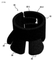
図3は本発明の好ましい第1実施例に係る位置固定装置の斜視図であり、図3の(a)は位置固定装置を広げた時の斜視図であり、図3の(b)は位置固定装置を結合した時の斜視図である。 Figure 3 is a perspective view of a position fixing device according to a first preferred embodiment of the present invention, where (a) of Figure 3 is a perspective view of the position fixing device when unfolded, and (b) of Figure 3 is a perspective view of the position fixing device when assembled.
図3を参照して本発明の好ましい第1実施例に係る前記位置固定装置30についてより詳細に説明すると、前記位置固定装置30は結合部32、固定部34を含む。
The
前記結合部32は、四角形状で前記冠状静脈洞チューブ10を囲むものである。前記結合部32は前記結合部32の左右方向の一端から延びるように突出形成された突出部32-1と、前記結合部32の左右方向の他端から一端に向かって陥入され前記突出部32-1の形状と対応するように形成された第1陥入部32-2と、前記結合部32の下端から上端に向かって陥入した第2陥入部32-3を含む。
The
前記結合部32は前記突出部32-1が前記第1陥入部32-2内に挿入された状態で前記冠状静脈洞チューブ10の外周面を囲むように結合され、結合後には全体的にリング状を有するものである。前記結合部32が前記冠状静脈洞チューブ10に結合時、人体に無害な接着剤のような接着物質を塗布して接着される。
The
前記突出部32-1および前記第1陥入部32-2が形成された前記結合部32の左右方向の両端は、前記冠状静脈洞の外壁と接触する位置に結合されることが好ましい。
It is preferable that both left and right ends of the
前記位置固定装置30は前記第2陥入部32-3の上端から延長形成されるものの、冠状静脈洞の内壁に挿入時に容易に挿入され、離脱時に容易に離脱され得るように前記三尖弁膜チューブに向かって所定の角度で傾いた多数個の固定部34を含む。前記固定部34は一端が前記第2陥入部32-3の上面と接触しており、他端は前記三尖弁膜チューブ20に向かって突出し、四角形状であるものの、一端から他端に行くほど幅方向の長さが長く形成され、角が角ばらずに丸く形成されるのが特徴である。
The
より詳細には、前記固定部34は前記冠状静脈洞の内壁と接触するように位置されて、前記冠状静脈洞チューブ10を冠状静脈洞に挿入すると前記固定部34が前記冠状静脈洞の内壁に固定される。
More specifically, the
前記冠状静脈洞は内壁が外壁より厚く形成されたもので、前記固定部34が冠状静脈洞の内壁に固定されても冠状静脈洞の内壁は損傷を受けないが、前記固定部34が冠状静脈洞の外壁に固定される場合、冠状静脈洞の外壁はその厚さが薄いため破れたり損傷を受け得る。
The coronary sinus has an inner wall that is thicker than the outer wall, so even if the fixing
したがって、本願発明に係る前記位置固定装置30は前記冠状静脈洞チューブ10に結合され、前記固定部34が冠状静脈洞の内壁に固定されるものであるため、前記冠状静脈洞チューブ10の滑りまたは位置移動は防止するものの冠状静脈洞に損傷は加えないのである。
Therefore, the
また、両側の角が丸く形成されるため、冠状静脈洞の内壁に固定されても冠状静脈洞の内壁に深い損傷を加えることなく前記冠状静脈洞チューブ10の位置を固定することができる。
In addition, since the corners on both sides are rounded, the position of the
前記結合部32は前記第1陥入部32-2と前記突出部32-1を含まないリングの形態も可能であることは言うまでもなく、前記第2陥入部32-3を含まずに前記結合部32の下端からすぐに延びて形成される前記固定部34を含んでもよいのは言うまでもない。
It goes without saying that the
図4は、本発明の好ましい第2実施例に係る位置固定装置の斜視図である。 Figure 4 is a perspective view of a position fixing device according to a second preferred embodiment of the present invention.
本発明の好ましい第2実施例に係る位置固定装置30は結合部32と固定部34を含む。前記結合部32は図3で詳述した通りであり、本発明の好ましい第2実施例に係る位置固定装置30は前記結合部32に結合された固定部34の個数が異なるものである。
The
第2実施例に係る位置固定装置30は、前記第2陥入部32-3の上面から一つの固定部34が延長形成されるものの、冠状静脈洞の内壁に挿入時に容易に挿入され、離脱時に容易に離脱され得るように前記三尖弁膜チューブに向かって所定の角度で傾いて形成される。より詳細には、前記固定部34の一端は前記第2陥入部32-3の上面と接触し、他端は前記三尖弁膜チューブに向かって突出し、四角形状であるものの、一端から他端に行くほど幅方向の長さが長く形成され、角が角ばらずに丸く形成されるのが特徴である。
In the second embodiment, the
本発明の好ましい第2実施例に係る前記位置固定装置30の前記固定部34は、第1実施例に係る前記固定部34より大きさが大きく形成されるものである。したがって、一つの前記固定部34が結合されても固定力が優秀であるのである。
The fixing
図5は、本発明の好ましい第3実施例に係る位置固定装置の斜視図である。本発明の好ましい第3実施例に係る位置固定装置30は結合部32と第1固定部37を含む。前記結合部32と前記第1固定部37は図3で詳述した結合部および固定部と同一の形状であるが、前記結合部32の高さ方向の長さが図3に図示されたものより長く形成される。
Figure 5 is a perspective view of a position fixing device according to a third preferred embodiment of the present invention. The
前記結合部32の一側には第2陥入部32-3と水平に四角形状の溝36が形成され、前記位置固定装置30は前記溝36の上面から延びて形成され、前記三尖弁膜チューブ20に向かって所定の角度で折り曲げられた多数個の第2固定部38を含む。前記第2固定部38は前記固定部34と同一に形成され、多数個の前記第2固定部38が所定の間隔をおいて互いに離隔するように形成される。
A
本発明の好ましい第3実施例に係る位置固定装置30は一つの前記位置固定装置30に前記第1固定部37および前記第2固定部38が形成されたものであるため、一つの前記位置固定装置30が前記冠状静脈洞チューブ10に接合されても固定力を向上させることができる。
In the third preferred embodiment of the present invention, the first fixing
図6は、本発明の好ましい第4実施例に係る位置固定装置の斜視図である。本発明の好ましい第4実施例に係る位置固定装置30は結合部32と第1固定部37を含み、前記結合部32の一側に第2陥入部32-3と水平に形成された四角形状の溝36を含み、前記溝36の上面から延びて形成され前記三尖弁膜チューブ20に向かって所定の角度で折り曲げられた一つの第2固定部38を含む。
Figure 6 is a perspective view of a position fixing device according to a fourth preferred embodiment of the present invention. The
前記結合部32と前記溝36は図5で詳述した通りであり、前記第1固定部37は前記第2陥入部32-3の上端から延長形成されるものの、冠状静脈洞の内壁に挿入時に容易に挿入され、離脱時に容易に離脱され得るように前記三尖弁膜チューブに向かって所定の角度で傾いた一つの固定部34を含む。
The
より詳細には、前記第1固定部37と前記第2固定部38は図4で詳述した本発明の好ましい第2実施例の固定部34と同一の形態であり、一つの前記第1固定部37および前記第2固定部38がそれぞれ前記第2陥入部32-3および前記溝36から延びて形成されるものの、前記三尖弁膜チューブ20に向かって所定の角度で折り曲げられて突出し、四角形状であるものの、一端から他端に行くほど幅方向の長さが長く形成され、角が角ばらずに丸く形成されるのが特徴である。
More specifically, the first fixing
本発明の好ましい第4実施例に係る位置固定装置30は一つの前記位置固定装置30に二つの固定部37、38が形成されたものであるため、一つの前記位置固定装置30のみが前記冠状静脈洞チューブ10に結合されても固定力をさらに向上させることができる。
In the fourth preferred embodiment of the present invention, the
図7は、本発明の好ましい第5実施例に係る位置固定装置の側面図である。本発明の第5実施例に係る位置固定装置30は結合部32と固定部34を含む。前記結合部32は図3で詳述した通りに形成される突出部32-1および第1陥入部32-2を含むか、第2陥入部32-3を含まないものである。
Figure 7 is a side view of a position fixing device according to a fifth preferred embodiment of the present invention. The
前記固定部34は、前記三尖弁膜チューブ20と向かい合うように位置される前記結合部32の下部の外周面に沿って外方に突出形成されるものである。より詳細には、前記固定部34は下端が最も突出するように上端から下端まで所定の傾斜を有して形成され、前記冠状静脈洞チューブ10が冠状静脈洞に挿入されると、前記固定部34の下端が冠状静脈洞の内壁の一側に係止されて前記冠状静脈洞チューブ10がそれ以上滑らないように防止する防止段のような役割をする。
The fixing
前記結合部32は前記固定部34が結合された左右側に溝が形成され得、これは前記結合部32が柔軟に曲がって前記冠状静脈チューブ10に結合され得るようにする。
The
図8は、本発明の好ましい第6実施例に係る位置固定装置の斜視図である。本発明の第6実施例に係る位置固定装置30は結合部32と固定部34を含む。前記結合部32は図3で詳述した通りに形成される突出部32-1および第1陥入部32-2を含むか、第2陥入部32-3を含まないものである。
Figure 8 is a perspective view of a position fixing device according to a sixth preferred embodiment of the present invention. The
前記結合部32の外周面に結合される多数個の固定部34を含み、前記固定部34は円錐状で前記三尖弁膜チューブ20と向かい合う前記結合部32の一側に多数個の列と行を有して配置される。前記固定部34はマイクロニードル(micro needle)のような形状で、より詳細には、大きさが1mm未満であり、円錐、多角錐、螺旋形のような多様な形態のマイクロニードルが適用され得る。
The fixing
より詳細には、前記固定部34は前記サークラージワイヤー1を引っ張ると冠状静脈洞の内壁に固定されて前記冠状静脈洞チューブ10の位置が固定されるようにするが、前記サークラージワイヤー1の張力を解除すると冠状静脈洞の内壁から容易に脱着され冠状静脈洞の内壁に損傷を加えないものである。
More specifically, when the
本願発明に係る位置固定装置を具備したサークラージ施術装置の施術方法について簡略に説明すると、まずサークラージ施術装置を体内に挿入する。この時、前記サークラージ施術装置は冠状静脈洞チューブ10、三尖弁膜チューブ20を基本的に含んで構成されるものであり、前記冠状静脈洞チューブ10の一側には位置固定装置30が一つ以上結合されたものである。また、前記三尖弁膜チューブ20の下端にはストッパー40を含むことができ、前記三尖弁膜チューブ20の外周面の一側には遮断部50を含むことができる。
Briefly, the method of the Circulage treatment device having the position fixing device according to the present invention will be described. First, the Circulage treatment device is inserted into the body. At this time, the Circulage treatment device is basically composed of a
次に、サークラージワイヤー1を上大静脈-冠状静脈洞チューブ10-心室中隔-三尖弁膜チューブ20に挿入して再び上大静脈に突出するようにする。この時、前記サークラージワイヤー1の一側にはアーチ部60を含むことができる。
Next, the
次に、上大静脈に位置する前記サークラージワイヤー1の両端を引っ張ると、前記サークラージワイヤー1に張力が加えられながら前記冠状静脈洞チューブ10が冠状静脈洞の内壁方向に移動して前記位置固定装置30が冠状静脈洞の内壁に固定される。
Next, when both ends of the
したがって、前記サークラージ施術装置が滑ったり心臓拍動によって移動しないようにして施術の安定性を向上させ、体内の正しい位置に装置が固定されて維持され得るようにする。 This prevents the circlage treatment device from slipping or moving due to cardiac pulsation, improving the stability of the treatment and allowing the device to be fixed and maintained in the correct position within the body.
以上、添付された図面を参照して本発明の実施例を説明したが、本発明が属する技術分野で通常の知識を有する者は、本発明がその技術的思想や必須の特徴を変更することなく他の具体的な形態で実施され得ることが理解できるであろう。したがって、以上で記述した実施例はすべての面で例示的なものであり限定的ではないものと理解されるべきである。 Although the embodiments of the present invention have been described above with reference to the attached drawings, those skilled in the art will understand that the present invention can be embodied in other specific forms without changing its technical concept or essential features. Therefore, the embodiments described above should be understood to be illustrative in all respects and not limiting.
Claims (10)
サークラージワイヤー;
冠状静脈洞に挿入されて内部に通孔が形成された冠状静脈洞チューブ;
三尖弁膜を横断し内部に通孔が形成された三尖弁膜チューブ;および
前記冠状静脈洞チューブの外周面の一側に接合され前記冠状静脈洞チューブの動きを防止する位置固定装置;を含むものの、
前記冠状静脈洞チューブと前記三尖弁膜チューブの上部側は結合され下部側は分離されており、
前記位置固定装置は、前記冠状静脈洞に固定されるように、前記冠状静脈洞チューブの外周面を囲むように設けられていることを特徴とする、位置固定装置を具備したサークラージ施術装置。 In a circlage treatment device equipped with a position fixing device,
Circular wire;
a coronary sinus tube having a hole formed therein and inserted into the coronary sinus;
a tricuspid valve tube having a through hole formed therein and crossing the tricuspid valve; and a position fixing device attached to one side of the outer circumferential surface of the coronary sinus tube to prevent movement of the coronary sinus tube;
The upper side of the coronary sinus tube and the tricuspid valve tube are connected and the lower side is separated ,
A circulage treatment device equipped with a position fixing device, characterized in that the position fixing device is provided to surround the outer circumferential surface of the coronary sinus tube so as to be fixed to the coronary sinus .
四角形状で前記冠状静脈洞チューブの前記下部において前記冠状静脈洞チューブの外周面を囲むように結合される結合部と、
前記結合部の下端から延びて形成されるものの、冠状静脈洞の内壁に挿入時に容易に挿入され、離脱時に容易に離脱され得るように前記三尖弁膜チューブの前記下部に向かって所定の角度で傾いた一つ以上の固定部を含むものの、
前記冠状静脈洞の内壁に前記固定部が固定され、前記冠状静脈洞の内壁より厚さが薄い前記冠状静脈洞の外壁には固定されないため前記冠状静脈洞の損傷を最小化することを特徴とする、請求項1に記載の位置固定装置を具備したサークラージ施術装置。 The position fixing device is
a coupling portion having a rectangular shape and coupled to the lower portion of the coronary sinus tube so as to surround an outer circumferential surface of the coronary sinus tube;
The connecting portion is formed extending from a lower end thereof, and includes one or more fixing portions inclined at a predetermined angle toward the lower portion of the tricuspid valve tube so that the fixing portion can be easily inserted into the inner wall of the coronary sinus during insertion and easily detached during detachment.
The circlage treatment device having the position fixing device according to claim 1, wherein the fixing part is fixed to the inner wall of the coronary sinus and is not fixed to the outer wall of the coronary sinus, which is thinner than the inner wall of the coronary sinus, thereby minimizing damage to the coronary sinus.
四角形状で前記冠状静脈洞チューブの前記下部において前記冠状静脈洞チューブの外周面を囲むように結合される結合部と、
前記結合部の下端から延びて形成されるものの、冠状静脈洞の内壁に挿入時に容易に挿入され、離脱時に容易に離脱され得るように前記三尖弁膜チューブの前記下部に向かって所定の角度で傾いた一つ以上の第1固定部と、
前記結合部の一側に形成された溝の上面から延びて形成されるものの、
冠状静脈洞の内壁に挿入時に容易に挿入され、離脱時に容易に離脱され得るように前記三尖弁膜チューブに向かって所定の角度で傾いた一つ以上の第2固定部を含むものの、
前記冠状静脈洞の内壁に前記第1固定部および前記第2固定部が固定され、前記冠状静脈洞の内壁より厚さが薄い前記冠状静脈洞の外壁には固定されないため前記冠状静脈洞の損傷を最小化することを特徴とする、請求項1に記載の位置固定装置を具備したサークラージ施術装置。 The position fixing device is
a coupling portion having a rectangular shape and coupled to the lower portion of the coronary sinus tube so as to surround an outer circumferential surface of the coronary sinus tube;
one or more first fixing parts extending from the lower end of the connecting part, the first fixing parts being inclined at a predetermined angle toward the lower part of the tricuspid valve tube so that the first fixing parts can be easily inserted into the inner wall of the coronary sinus and easily detached from the tricuspid valve tube;
The groove is formed on one side of the coupling portion, and extends from the upper surface of the groove.
one or more second fixing parts inclined at a predetermined angle toward the tricuspid valve tube so that the second fixing parts can be easily inserted into the inner wall of the coronary sinus during insertion and easily detached during detachment,
The circulaire treatment device having the position fixing device according to claim 1, characterized in that the first fixing part and the second fixing part are fixed to the inner wall of the coronary sinus and are not fixed to the outer wall of the coronary sinus, which is thinner than the inner wall of the coronary sinus, thereby minimizing damage to the coronary sinus.
四角形状で前記冠状静脈洞チューブの外周面を囲むように結合される結合部と、
前記結合部の一側面に下部の外周面に沿って外方に突出形成される固定部を含むものの、
前記固定部は下端が最も突出するように上端から下端まで所定の傾斜を有して形成されることを特徴とする、請求項1に記載の位置固定装置を具備したサークラージ施術装置。 The position fixing device is
a coupling portion having a rectangular shape and coupled to the coronary sinus tube so as to surround the outer circumferential surface of the coronary sinus tube;
The coupling portion includes a fixing portion formed on one side thereof and protruding outward along a lower outer circumferential surface thereof,
2. The circlage treatment device having the position fixing device according to claim 1, wherein the fixing portion is formed with a predetermined inclination from the upper end to the lower end so that the lower end protrudes most.
四角形状で前記冠状静脈洞チューブの外周面を囲むように結合される結合部と、
前記結合部の一側面に多数個の行と列を有するように配置され、マイクロニードルの形状を有する多数個の固定部を含むことを特徴とする、請求項1に記載の位置固定装置を具備したサークラージ施術装置。 The position fixing device is
a coupling portion having a rectangular shape and coupled to the coronary sinus tube so as to surround the outer circumferential surface of the coronary sinus tube;
The circulaire treatment device having the position fixing device according to claim 1, comprising a plurality of fixing parts having a shape of microneedles, arranged in a plurality of rows and columns on one side of the coupling part.
前記冠状静脈洞の内壁に固定され、前記冠状静脈洞の内壁より厚さが薄い前記冠状静脈洞の外壁には固定されないため前記冠状静脈洞の損傷を最小化することを特徴とする、請求項1に記載の位置固定装置を具備したサークラージ施術装置。 The position fixing device is
The circlage treatment device having the position fixing device according to claim 1, which is fixed to the inner wall of the coronary sinus and is not fixed to the outer wall of the coronary sinus, which is thinner than the inner wall of the coronary sinus, thereby minimizing damage to the coronary sinus.
前記冠状静脈洞チューブに沿って一個以上が結合されることを特徴とする、請求項1に記載の位置固定装置を具備したサークラージ施術装置。 The position fixing device is
2. The circulaire treatment device with a position fixing device according to claim 1, wherein one or more are connected along the coronary sinus tube.
Applications Claiming Priority (3)
| Application Number | Priority Date | Filing Date | Title |
|---|---|---|---|
| KR10-2019-0084508 | 2019-07-12 | ||
| KR1020190084508A KR102240805B1 (en) | 2019-07-12 | 2019-07-12 | Apparatus for cerclage annuloplasty with position fixing device |
| PCT/KR2020/009127 WO2021010679A2 (en) | 2019-07-12 | 2020-07-10 | Cerclage operation device provided with position fixing device |
Publications (3)
| Publication Number | Publication Date |
|---|---|
| JP2022541889A JP2022541889A (en) | 2022-09-28 |
| JP2022541889A5 JP2022541889A5 (en) | 2024-06-17 |
| JP7526251B2 true JP7526251B2 (en) | 2024-07-31 |
Family
ID=74211126
Family Applications (1)
| Application Number | Title | Priority Date | Filing Date |
|---|---|---|---|
| JP2022502180A Active JP7526251B2 (en) | 2019-07-12 | 2020-07-10 | Circulare treatment device equipped with a position fixing device |
Country Status (6)
| Country | Link |
|---|---|
| US (2) | US20220296371A1 (en) |
| EP (1) | EP3998043A4 (en) |
| JP (1) | JP7526251B2 (en) |
| KR (1) | KR102240805B1 (en) |
| CN (1) | CN114222545B (en) |
| WO (1) | WO2021010679A2 (en) |
Families Citing this family (2)
| Publication number | Priority date | Publication date | Assignee | Title |
|---|---|---|---|---|
| CN114514004B (en) * | 2019-10-03 | 2024-12-06 | Tau医疗公司 | Devices, systems and methods for reducing mitral regurgitation |
| USD1080862S1 (en) * | 2022-12-30 | 2025-06-24 | Tau Medical Inc. | Transcatheter device for treating tricuspid valve regurgitation |
Citations (1)
| Publication number | Priority date | Publication date | Assignee | Title |
|---|---|---|---|---|
| WO2019103540A1 (en) | 2017-11-24 | 2019-05-31 | 주식회사 타우피엔유메디칼 | Cerclage atrial defibrillator |
Family Cites Families (18)
| Publication number | Priority date | Publication date | Assignee | Title |
|---|---|---|---|---|
| WO2000010631A1 (en) * | 1998-08-24 | 2000-03-02 | Yacoubian Vahe S | Venous return catheter with anchor means and method for use |
| JP4195612B2 (en) | 2001-01-30 | 2008-12-10 | エドワーズ ライフサイエンシーズ アーゲー | Medical system and method for improving extracorporeal tissue structure |
| EP1513474B1 (en) * | 2002-05-08 | 2008-12-17 | Cardiac Dimensions, Inc. | Device for modifying the shape of a mitral valve |
| US8721710B2 (en) * | 2003-08-11 | 2014-05-13 | Hdh Medical Ltd. | Anastomosis system and method |
| US7503932B2 (en) | 2006-04-11 | 2009-03-17 | Cardiac Dimensions, Inc. | Mitral valve annuloplasty device with vena cava anchor |
| WO2009039400A1 (en) * | 2007-09-20 | 2009-03-26 | Nanostim, Inc. | Leadless cardiac pacemaker with secondary fixation capability |
| KR101116867B1 (en) | 2009-08-28 | 2012-03-06 | 김준홍 | The device for delivering optimal tension safaely and effectively in cerclage annuloplasty procedure |
| KR101231140B1 (en) | 2011-08-12 | 2013-02-07 | 부산대학교 산학협력단 | Appartus for cerclage annuloplasty procedure |
| KR20130074823A (en) | 2011-12-23 | 2013-07-05 | 김준홍 | Interventricular septum insert and apparatus for inserting it in cerclage annuloplasty procedure |
| KR101467373B1 (en) * | 2013-05-23 | 2014-12-10 | 부산대학교 산학협력단 | Stopper for myocardial protection and cerclage annuloplasty procedure apparatus with the same |
| KR101574768B1 (en) * | 2014-02-17 | 2015-12-04 | 동국대학교 산학협력단 | Wire locking device for medical procedure |
| KR101563172B1 (en) | 2014-05-20 | 2015-10-27 | (주) 타우피엔유메디칼 | Tissue protective device for the cerclage annuloplasty procedure |
| KR101581021B1 (en) | 2014-05-28 | 2015-12-29 | (주) 타우피엔유메디칼 | Tissue protective device for the cerclage annuloplasty procedure in use of the coil spring, and tissue protective device making method |
| KR20150144568A (en) | 2014-06-17 | 2015-12-28 | (주) 타우피엔유메디칼 | Tissue protective tube for tricuspid regurgitation |
| KR20160011530A (en) | 2014-07-22 | 2016-02-01 | 부산대학교 산학협력단 | Devices and Method of trans-coronary sinus intraseptal pacing in the lead end of the cardiac pacemaker |
| KR20160020887A (en) | 2014-08-14 | 2016-02-24 | 부산대학교 산학협력단 | Devices and Method of trans-coronary sinus mid to apical interventricular septal pacing in the lead end of the cardiac pacemaker |
| KR101805679B1 (en) | 2017-02-01 | 2017-12-06 | (주) 타우피엔유메디칼 | Device for transcatheter treatment for tricuspid regurgitation |
| KR101955291B1 (en) * | 2017-10-25 | 2019-03-08 | (주) 타우피엔유메디칼 | A device to treat heart valve regurgitation and fix the pacemaker lead |
-
2019
- 2019-07-12 KR KR1020190084508A patent/KR102240805B1/en active Active
-
2020
- 2020-07-10 JP JP2022502180A patent/JP7526251B2/en active Active
- 2020-07-10 EP EP20840019.2A patent/EP3998043A4/en active Pending
- 2020-07-10 CN CN202080057718.8A patent/CN114222545B/en active Active
- 2020-07-10 WO PCT/KR2020/009127 patent/WO2021010679A2/en not_active Ceased
- 2020-07-10 US US17/626,808 patent/US20220296371A1/en not_active Abandoned
-
2025
- 2025-09-11 US US19/326,615 patent/US20260007517A1/en not_active Abandoned
Patent Citations (1)
| Publication number | Priority date | Publication date | Assignee | Title |
|---|---|---|---|---|
| WO2019103540A1 (en) | 2017-11-24 | 2019-05-31 | 주식회사 타우피엔유메디칼 | Cerclage atrial defibrillator |
Also Published As
| Publication number | Publication date |
|---|---|
| US20260007517A1 (en) | 2026-01-08 |
| US20220296371A1 (en) | 2022-09-22 |
| EP3998043A2 (en) | 2022-05-18 |
| JP2022541889A (en) | 2022-09-28 |
| WO2021010679A3 (en) | 2021-05-20 |
| KR102240805B1 (en) | 2021-04-15 |
| EP3998043A4 (en) | 2023-07-26 |
| CN114222545A (en) | 2022-03-22 |
| KR20210007670A (en) | 2021-01-20 |
| WO2021010679A2 (en) | 2021-01-21 |
| CN114222545B (en) | 2025-04-04 |
Similar Documents
| Publication | Publication Date | Title |
|---|---|---|
| US12016538B2 (en) | Tissue shaping device | |
| JP6422082B2 (en) | Temporary atrial support device | |
| ES2959195T3 (en) | Expandable heart lead and delivery system | |
| JP2025169955A (en) | Shunt systems and methods with prevention of tissue growth - Patents.com | |
| ES2322552T3 (en) | MITRAL VALVE CONSTRUCTION DEVICE AND SYSTEM. | |
| US20260007517A1 (en) | Cerclage operation device provided with position fixing device | |
| JP6898037B2 (en) | Tricuspid regurgitation surgical instrument | |
| ES2558860T3 (en) | Device and method of fixed length traction anchor and mitral valve | |
| US7899555B2 (en) | Intrapericardial lead | |
| KR102053451B1 (en) | Cerclage atrial implantable cardioverter defibrillators | |
| JP7821106B2 (en) | Mechanically Expandable Shunt Implants | |
| EP3158940B1 (en) | Tissue protection device for tricuspid regurgitation surgery | |
| EP3146904B1 (en) | Tissue protection device for mitral valve membrane cerclage procedure | |
| JP2016508389A5 (en) | ||
| US20060161169A1 (en) | Device and method for modifying the shape of a body organ | |
| JP2023542116A (en) | compression shunt implant | |
| CA2775968A1 (en) | Cannula stabilizer | |
| JP2022541889A5 (en) | ||
| KR101955291B1 (en) | A device to treat heart valve regurgitation and fix the pacemaker lead | |
| KR102754881B1 (en) | Implantable artificial heart valves and medical devices | |
| KR20200132320A (en) | A device for the treatment of tricuspid regurgitation with position fixing tube | |
| US7865248B2 (en) | Biasing and fixation features on leads | |
| KR102089363B1 (en) | Wire connection device for mitral valve procedure | |
| CN110665123A (en) | Pace-making catheter, magnetic attachment and pace-making catheter kit | |
| ES2952592T3 (en) | Device for arranging guide wires around a heart valve |
Legal Events
| Date | Code | Title | Description |
|---|---|---|---|
| A621 | Written request for application examination |
Free format text: JAPANESE INTERMEDIATE CODE: A621 Effective date: 20230627 |
|
| A131 | Notification of reasons for refusal |
Free format text: JAPANESE INTERMEDIATE CODE: A131 Effective date: 20240312 |
|
| A977 | Report on retrieval |
Free format text: JAPANESE INTERMEDIATE CODE: A971007 Effective date: 20240313 |
|
| A524 | Written submission of copy of amendment under article 19 pct |
Free format text: JAPANESE INTERMEDIATE CODE: A524 Effective date: 20240607 |
|
| TRDD | Decision of grant or rejection written | ||
| A01 | Written decision to grant a patent or to grant a registration (utility model) |
Free format text: JAPANESE INTERMEDIATE CODE: A01 Effective date: 20240716 |
|
| A61 | First payment of annual fees (during grant procedure) |
Free format text: JAPANESE INTERMEDIATE CODE: A61 Effective date: 20240719 |
|
| R150 | Certificate of patent or registration of utility model |
Ref document number: 7526251 Country of ref document: JP Free format text: JAPANESE INTERMEDIATE CODE: R150 |