JP7528107B2 - Orbital cutting device and tube adjustment device - Google Patents
Orbital cutting device and tube adjustment device Download PDFInfo
- Publication number
- JP7528107B2 JP7528107B2 JP2021549954A JP2021549954A JP7528107B2 JP 7528107 B2 JP7528107 B2 JP 7528107B2 JP 2021549954 A JP2021549954 A JP 2021549954A JP 2021549954 A JP2021549954 A JP 2021549954A JP 7528107 B2 JP7528107 B2 JP 7528107B2
- Authority
- JP
- Japan
- Prior art keywords
- tube
- cutting
- support
- rotor
- adjustment tool
- Prior art date
- Legal status (The legal status is an assumption and is not a legal conclusion. Google has not performed a legal analysis and makes no representation as to the accuracy of the status listed.)
- Active
Links
Images






Classifications
-
- B—PERFORMING OPERATIONS; TRANSPORTING
- B21—MECHANICAL METAL-WORKING WITHOUT ESSENTIALLY REMOVING MATERIAL; PUNCHING METAL
- B21D—WORKING OR PROCESSING OF SHEET METAL OR METAL TUBES, RODS OR PROFILES WITHOUT ESSENTIALLY REMOVING MATERIAL; PUNCHING METAL
- B21D3/00—Straightening or restoring form of metal rods, metal tubes, metal profiles, or specific articles made therefrom, whether or not in combination with sheet metal parts
- B21D3/14—Recontouring
-
- B—PERFORMING OPERATIONS; TRANSPORTING
- B21—MECHANICAL METAL-WORKING WITHOUT ESSENTIALLY REMOVING MATERIAL; PUNCHING METAL
- B21D—WORKING OR PROCESSING OF SHEET METAL OR METAL TUBES, RODS OR PROFILES WITHOUT ESSENTIALLY REMOVING MATERIAL; PUNCHING METAL
- B21D41/00—Application of procedures in order to alter the diameter of tube ends
- B21D41/02—Enlarging
-
- B—PERFORMING OPERATIONS; TRANSPORTING
- B23—MACHINE TOOLS; METAL-WORKING NOT OTHERWISE PROVIDED FOR
- B23B—TURNING; BORING
- B23B27/00—Tools for turning or boring machines; Tools of a similar kind in general; Accessories therefor
- B23B27/04—Cutting-off tools
- B23B27/045—Cutting-off tools with chip-breaking arrangements
-
- B—PERFORMING OPERATIONS; TRANSPORTING
- B23—MACHINE TOOLS; METAL-WORKING NOT OTHERWISE PROVIDED FOR
- B23D—PLANING; SLOTTING; SHEARING; BROACHING; SAWING; FILING; SCRAPING; LIKE OPERATIONS FOR WORKING METAL BY REMOVING MATERIAL, NOT OTHERWISE PROVIDED FOR
- B23D21/00—Machines or devices for shearing or cutting tubes
- B23D21/006—Machines or devices for shearing or cutting tubes and sealing, crushing or chamfering the tubes
-
- B—PERFORMING OPERATIONS; TRANSPORTING
- B23—MACHINE TOOLS; METAL-WORKING NOT OTHERWISE PROVIDED FOR
- B23D—PLANING; SLOTTING; SHEARING; BROACHING; SAWING; FILING; SCRAPING; LIKE OPERATIONS FOR WORKING METAL BY REMOVING MATERIAL, NOT OTHERWISE PROVIDED FOR
- B23D21/00—Machines or devices for shearing or cutting tubes
- B23D21/04—Tube-severing machines with rotating tool-carrier
-
- B—PERFORMING OPERATIONS; TRANSPORTING
- B26—HAND CUTTING TOOLS; CUTTING; SEVERING
- B26D—CUTTING; DETAILS COMMON TO MACHINES FOR PERFORATING, PUNCHING, CUTTING-OUT, STAMPING-OUT OR SEVERING
- B26D3/00—Cutting work characterised by the nature of the cut made; Apparatus therefor
- B26D3/16—Cutting rods or tubes transversely
- B26D3/166—Trimming tube-ends
-
- B—PERFORMING OPERATIONS; TRANSPORTING
- B23—MACHINE TOOLS; METAL-WORKING NOT OTHERWISE PROVIDED FOR
- B23B—TURNING; BORING
- B23B27/00—Tools for turning or boring machines; Tools of a similar kind in general; Accessories therefor
- B23B27/08—Cutting tools with blade- or disc-like main parts
Landscapes
- Engineering & Computer Science (AREA)
- Mechanical Engineering (AREA)
- Life Sciences & Earth Sciences (AREA)
- Forests & Forestry (AREA)
- Turning (AREA)
- Analysing Materials By The Use Of Radiation (AREA)
- Investigating Or Analyzing Materials By The Use Of Magnetic Means (AREA)
- Length-Measuring Devices Using Wave Or Particle Radiation (AREA)
Description
本発明は、チューブの軌道切断装置と、切断後にチューブの調整を行う装置に関する。 The present invention relates to a tube orbital cutting device and a device for adjusting the tube after cutting.
円形断面を有するチューブ、例えば、曲げ加工機で曲げられるか又はチューブエンド成形機でチューブ端部が変形されるチューブを切断するいわゆる軌道切断方法が知られている。 The so-called orbital cutting method is known for cutting tubes with a circular cross section, for example tubes that are bent in a bending machine or whose ends are deformed in a tube end forming machine.
円形断面のチューブを軌道切断するのは、もとのチューブバー又はチューブコイルからチューブ片を分離するために、切断ローラとして一般に知られている円形カッターをチューブの周りに旋回させてチューブに漸次切り込みを入れることによって行われる、チップ除去を行うことない処理である。次に、チューブ片は、以下の公知方法のいずれかによって、チューブバー又はチューブコイルから分離される。前記パイプにその厚み分を完全に貫通するように切断ローラが漸次切り込みを入れるスルーカット。切断ローラがチューブの厚み分を完全に貫通することなくチューブに漸次切り込みを入れ、切断ローラの前進中又はその直後にチューブを引っ張ってチューブ片が分離される、切り込みと破壊。切断ローラが、チューブの厚み分を完全に貫通することなくチューブに漸次溝を形成し、チューブ片はチューブを曲げることによって分離される、切り込みとスナップ。 Orbital cutting of circular cross-section tubes is a non-chip removal process in which a circular cutter, commonly known as a cutting roller, is rotated around the tube to progressively cut into the tube to separate the tube pieces from the original tube bar or tube coil. The tube pieces are then separated from the tube bar or tube coil by one of the following known methods: Through-cut, in which the cutting roller progressively cuts into the tube completely through its thickness; Slit and break, in which the cutting roller progressively cuts into the tube without completely cutting through the thickness of the tube, and the tube pieces are separated by pulling on the tube during or immediately after the cutting roller advances; Slit and snap, in which the cutting roller progressively grooves the tube without completely cutting through the thickness of the tube, and the tube pieces are separated by bending the tube.
添付図面の図1は、チューブを供給し切断するラインの公知例を示す。このラインは、棒状チューブT(おそらく、曲げられて真っすぐにされたチューブコイルから生じたチューブ)を供給する供給ユニット10と、チューブTをクランプするクランプユニット12と、チューブTを旋回切断する切断ユニット14と、切断ユニット14によって切断された後、チューブTの一部を破壊する破壊ユニット16を有する。チューブ片の分離が上述のスルーカット法によって行われる場合、破壊ユニット16は設けられない又は使用されない。
Figure 1 of the accompanying drawings shows a known example of a tube feeding and cutting line. The line has a
切断ユニット14は添付図面の図2,3に具体的に示されており、図3は図2の細部Aの拡大図を示す。
The
図2,3を参照すると、切断ユニット14は、中央の孔20を有するロータ18を含む。中央の孔20は、この孔を介して、切断するチューブTが送られる。ロータ18は、切断ローラ24を運ぶ支持体22が取り付けられている。ロータ18は、例えば、電動モータ26を有するギヤモータユニットによって駆動されて、チューブTの長軸に一致する第1回転軸x1を中心に回転する。支持体22は、ロータ18に対して、径方向(符号yで示される。)に移動可能である。切断ローラ24は、支持体22に対して、第1回転軸x1に平行な第2回転軸x2を中心に自由に回転可能である。
With reference to Figures 2 and 3, the
添付図面の図4~7を参照すると、図2,3に示されるように、切断ユニットによるチューブTの切断プロセスは、(説明を簡単にするために、供給ユニット10によって供給されるチューブバーからチューブ片を分離する貫通切断技術を考えると、)以下の工程に従って行われる。 With reference to Figures 4 to 7 of the accompanying drawings, as shown in Figures 2 and 3, the cutting process of the tube T by the cutting unit is carried out according to the following steps (considering, for ease of explanation, a through-cutting technique for separating tube pieces from a tube bar supplied by the supply unit 10):
はじめに(図4)、チューブTは、切断されるチューブTの断面が切断ローラ24に位置づけされるまで、軸方向(すなわち、ロータ18の回転軸x1に一致するチューブの長軸方向)に移動される。
First (Figure 4), the tube T is moved axially (i.e., along the longitudinal axis of the tube, which coincides with the axis of rotation x1 of the rotor 18) until the cross section of the tube T to be cut is positioned on the
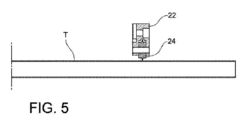
この時点(図5)で、切断ローラ24がチューブTの表面に接触し、支持体22がチューブTの長軸に向かって径方向に移動する。また、ロータ18が駆動されて第1回転軸x1を中心に回転し、切断ローラ24がチューブTの周りを旋回する。
At this point (FIG. 5), the
図6に示されるように、ロータ18の回転動作中、支持体22と、それによって運ばれる切断ローラ24は、チューブTの長軸に向かって径方向に移動される。その結果、切断ローラ24は、チューブの厚み方向に、漸次深くなる周方向の溝Cを、チューブ片(符号Pで示される。)が分離するまで形成する。
As shown in FIG. 6, during the rotational movement of the
最後に、図7に示されるように、ロータ18の回転が中断され、切断ローラ24は、チューブTの表面から離れた径方向のスタート位置に戻される。
Finally, as shown in FIG. 7, rotation of the
軌道切断プロセスは、チューブの外側から内側への切断ローラの押し込みによって、チューブの内側に向かって材料が径方向に移動し、その結果チューブの内径が減少する、という欠点がある。また、チューブの外径が小さくなることによってチューブの内径が小さくなることに加えて、バリの発生によってチューブの内径が減少することも考慮しなければならない。 The orbital cutting process has the disadvantage that the cutting rollers pushing from the outside to the inside of the tube causes a radial movement of material towards the inside of the tube, resulting in a reduction in the inside diameter of the tube. In addition to the reduction in the outside diameter of the tube, which reduces the inside diameter of the tube, it must also be considered that the reduction in the inside diameter of the tube occurs due to the generation of burrs.
チューブの内径が減少することは、その後のチューブの処理(特に、コアを使ったチューブの曲げ)に影響を与えるため(切断部の周りの領域におけるチューブの内径が減少すると、チューブの内径よりも小さな径のコアを使用しなければならず、そのために曲げ不良を生じる危険がある。)、また、仕上げ製品の機能に影響を与えるため、望ましくない切断の影響である。 A reduction in the inner diameter of the tube is an undesirable effect of the cut because it affects subsequent processing of the tube (especially bending the tube using a core) (if the inner diameter of the tube in the area around the cut is reduced, a core with a smaller diameter must be used, which risks bending the tube poorly) and because it affects the functionality of the finished product.
軌道切断の結果としてチューブの内径が減少することは、ツールの寸法(大きさ、レーキ角、鋭さ等。ただし、後者は使用と共に減少しがちである。)、切断パラメータ(例えば、貫通速度)、及び加工されるチューブの冶金学的特性に結びついた、数々の要因と密接に関連している。 The reduction in the inside diameter of the tube as a result of orbital cutting is closely related to a number of factors linked to the tool dimensions (size, rake angle, sharpness, etc., although the latter tend to decrease with use), the cutting parameters (e.g., penetration rate), and the metallurgical properties of the tube being processed.
これら種々の要因により、作業中にチューブの内径の減少を許容範囲に安定して収めることは常に行えるものではない。 Due to these various factors, it is not always possible to stably keep the reduction in the tube's inner diameter within an acceptable range during operation.
したがって、軌道切断後、切断ユニットの下流側に配置された特別なユニットで、チューブの内径を公称値に戻すために、切断されたチューブ片に調整処理を施すことが知られている。この調整処理は、例えば、トリミング処理やバリ取り処理を含む。 It is therefore known to subject the cut tube pieces to conditioning operations in special units arranged downstream of the cutting unit after the orbital cutting in order to return the inner diameter of the tube to its nominal value. These conditioning operations include, for example, trimming and deburring operations.
しかし、この解決策は、切断ユニットと調整ユニットとの間でチューブは適正に扱われなければならないうえに、調整処理で発生した廃棄物を適正に扱わなければならないことから、特別な処理ユニットを設ける必要があり、工場のコスト・大きさ・複雑さが増加するため、最適なものではない。また、このような付加的な処理を行うことは、サイクルタイムが増加し、チューブ処理工場(例えば、曲げ処理)の生産性を損なう結果となる。 However, this solution is not optimal because the tubes must be properly handled between the cutting and conditioning units, and the waste generated during the conditioning process must be properly handled, which requires special processing units, increasing the cost, size and complexity of the plant. Furthermore, the implementation of such additional processing increases the cycle time, resulting in a loss of productivity in the tube processing plant (e.g. bending).
また、いわゆる「プッシュ」技術に従って調整処理(すなわち、チューブに対して同軸に配置された特別なパンチを使ってチューブを所定距離(例えば、数ミリメートル)だけ内側に押す処理)を行い、チューブの内径を大きくすることが知られている。しかし、調整によって調整の課題を解消する一方で、プッシュ調整はバリをチューブの内側に移動させるという欠点があり、その後のチューブ加工工程やチューブの最終仕様段階で問題を生じる。 It is also known to increase the inner diameter of the tube by performing a fitting process according to the so-called "push" technique (i.e. pushing the tube inwards a given distance (e.g. a few millimeters) using a special punch arranged coaxially with respect to the tube). However, while fitting solves the fitting problem, push fitting has the drawback of moving burrs to the inside of the tube, which creates problems during the subsequent tube processing steps and during the final specification stage of the tube.
したがって、本発明の目的は、上述した従来の欠点によって影響を受けることがない、チューブの軌道切断装置を提供するとともに、切断後の調整のための装置を提供することである。 The object of the present invention is therefore to provide a tube orbital cutting device that is not affected by the above-mentioned conventional disadvantages, and to provide a device for post-cutting adjustment.
この目的及びその他の目的は、添付の特許請求の範囲の請求項1に記載の特徴を有する装置の発明によって完全に達成される。 This and other objects are fully achieved by the invention of a device having the features set out in claim 1 of the accompanying claims.
本発明の利点は、従属請求項に記載されている。その内容は、以下の説明の一体的部分として理解される。
要するに、本発明は、チューブを切断し調整する装置を創造するアイデアに基づき、切断されるチューブが移動される中央孔を有し、第1回転軸の周りを回転するように駆動可能なロータと、
前記ロータ上に径方向に移動可能に設けられた第1支持体と、前記第1支持体によって運ばれる切断ツールを含む切断デバイスと、
前記ロータ上に径方向に移動可能に設けられた第2支持体と、前記第2支持体によって運ばれる調整ツールとを含む調整デバイスとを有し、
前記調整ツールは、チューブ片の内径を拡大するために、径方向外側に移動可能である。
Advantages of the invention are set forth in the dependent claims, the content of which is to be understood as an integral part of the following description.
In summary, the invention is based on the idea of creating a device for cutting and trimming tubes, comprising a rotor having a central hole through which the tube to be cut is moved and which can be driven to rotate about a first axis of rotation;
a first support disposed radially movably on the rotor; and a cutting device including a cutting tool carried by the first support;
an adjustment device including a second support radially movably mounted on the rotor and an adjustment tool carried by the second support;
The adjustment tool is movable radially outward to increase the inner diameter of the tube segment.
この装置は、同じロータの上に設けられた、切断デバイスと調整デバイスを有する。切断後にチューブを調整するために、切断ユニットの下流に追加の処理ユニットを設ける必要がない。したがって、追加ユニットの存在に関連した上述したすべての欠点が解消される。また、調整ツールは、ロータに対して又と加工されるチューブに対して径方向に移動可能な支持体に設けられている。そのため、チューブの調整は、プッシュ調整のように、チューブに対してツールを、チューブの長軸に沿って軸方向に移動する手段ではなく、径方向に移動する手段によって行われる。したがって、プッシュ調整に典型的なチューブの内側へバリを移動するという問題が解消される。 The apparatus has a cutting device and an adjustment device mounted on the same rotor. No additional processing units are required downstream of the cutting unit to adjust the tube after cutting. All the above-mentioned drawbacks associated with the presence of additional units are therefore eliminated. Also, the adjustment tool is mounted on a support that is movable radially with respect to the rotor and with respect to the tube to be processed. The tube is therefore adjusted by means of radial movement of the tool relative to the tube, rather than axially along the tube's long axis, as in push adjustment. The problem of moving burrs to the inside of the tube, typical of push adjustment, is therefore eliminated.
好ましくは、第1支持体と第2支持体は別々のもので、それらは同じ径方向に移動するように、ロータに設けられる。しかし、これに代えて、切断ツールと調整ツールの両方の機能を実行する一つの支持体を設けてもよい。 Preferably, the first and second supports are separate and mounted on the rotor so that they move in the same radial direction. However, alternatively, there may be one support that performs the functions of both the cutting tool and the adjustment tool.
1つの実施形態によれば、ロータ(チューブ)に対して第1支持体と第2支持体(及び、切断ツールと調整ツール)を径方向に移動するために、装置は、第1支持体と第2支持体の両方と対になる一つの駆動装置を有し、ロータの回転軸(すなわち、チューブの長軸)に対して対称にそれら支持体の径方向移動を制御する。代わりに、第1駆動装置と第2駆動装置を設けてもよい。これらの駆動装置は、それぞれが対応する支持体と対をなし、第1支持体と第2支持体の径方向移動は互いに独立して駆動される。 According to one embodiment, to move the first and second supports (and the cutting tool and the adjustment tool) radially relative to the rotor (tube), the device has one drive paired with both the first and second supports and controls the radial movement of the supports symmetrically with respect to the rotor's rotation axis (i.e. the longitudinal axis of the tube). Alternatively, a first drive and a second drive may be provided, each paired with a corresponding support, and the radial movement of the first and second supports is driven independently of each other.
好ましくは、切断ツールはローラによって形成される。ローラは、第1回転軸に平行な第2回転軸を中心に回転可能に第1支持体に設けられ、周方向の切断エッジを有する。 Preferably, the cutting tool is formed by a roller. The roller is mounted on the first support so as to be rotatable about a second axis of rotation parallel to the first axis of rotation and has a circumferential cutting edge.
調整ツールに関する限り、塑性変形又はチップ除去によって、チューブを拡大するように構成してもよい。この別の形態の場合、調整ツールには、チューブの端部を加工するために適当の形に作られた切断エッジが設けられる。 As far as the adjustment tool is concerned, it may be configured to enlarge the tube by plastic deformation or chip removal. In this alternative form, the adjustment tool is provided with a cutting edge suitably shaped to process the end of the tube.
請求項9に記載の本発明のさらなる主題は、コイルからのチューブを真っ直ぐにして切断するための機械等のチューブを加工する機械で、上述した特徴を有する、チューブを切断し調整する装置を有する。 A further subject of the invention, as set forth in claim 9, is a machine for processing tubes, such as a machine for straightening and cutting tubes from coils, comprising a device for cutting and trimming the tubes, having the above-mentioned characteristics.
1つの実施形態によれば、その機械は、以下の工程を実行するように構成される。
回転中のロータを用いて、切断ツールの手段によってチューブからチューブ片を切り出す工程。
前記チューブ片を、前記チューブの残余部から軸方向に移動して離す工程。
前記調整ツールを、前記チューブの径方向の寸法内の所定位置に到達するまで、前記チューブの長軸に向かって径方向に移動する工程。
前記チューブ片を前記調整ツールに対して軸方向に移動する工程。
ロータを回転しながら、前記調整ツールを径方向外側に移動して前記チューブ片の内径を拡大する工程。
According to one embodiment, the machine is configured to perform the following steps.
Using the rotating rotor to cut tube sections from the tube by means of a cutting tool.
Axial moving the tube section away from the remainder of the tube.
Moving the adjustment tool radially toward the longitudinal axis of the tube until it reaches a predetermined position within the radial dimension of the tube.
Axial moving the tube segment relative to the adjustment tool.
While rotating the rotor, the adjustment tool is moved radially outward to increase the inner diameter of the tube segment.
本発明の更なる特徴と利点は、添付図面を参照して、非限定的な実施例として提供される以下の詳細な説明からさらに明らかになる。 Further features and advantages of the present invention will become more apparent from the following detailed description, given by way of non-limiting example with reference to the accompanying drawings, in which:
まず図8,9を参照すると、そこでは図1~7(従来技術)の符号と同じ符号又は対応する符号の部品と要素は、同じ参照符号が割り当てられており、チューブTの切断と、チューブ片Pの内径を初期の値(公称径)に戻すために、切断されたチューブ片Pの調整を行うように構成された、調整装置(以下、便宜上単に「装置」という。)が、概略符号14で示されている。 Referring first to Figures 8 and 9, in which parts and elements having the same or corresponding numbers as those in Figures 1 to 7 (prior art) are assigned the same reference numerals, an adjustment device (hereinafter, for convenience, simply referred to as "device") configured to cut the tube T and adjust the cut tube piece P to return the inner diameter of the tube piece P to an initial value (nominal diameter) is generally indicated by the numeral 14.
装置14は、中央の孔20を備えたロータ18を有する。この孔20を介して、切断されるチューブTは、供給ユニット(ここでは図示しないが、それ自体は公知のものである。例えば、図1の供給ユニット10を参照。)によってチューブの長軸に沿って移動される。ロータ18は、チューブTの長軸に一致する第1回転軸x1を中心に回転するように支持されている。装置14はまた、ロータ18を駆動して第1回転軸x1を中心に回転するために、第1駆動装置26(例えば、電動式ギヤモータ)を有する。
The
ロータ18には、例えば鋭い周囲のエッジを有するローラとして構成された切断ツール24を運ぶ支持体22が装着されている。切断ツール24は、支持体22に対して、第1回転軸x1に平行な第2回転軸x2を中心に自由に回転可能である。
The
支持体22は、径方向yに沿って、ロータ18に対して移動可能である。この点に関して、支持体22は、例えば、径方向yに沿って延在するロータ18のスロット30にスライド可能に設けられたスライダ28にしっかりと連結されている。第2駆動装置32(例えば、電ギヤモータ)は、径方向yに沿ってスライダ28及び支持体22を移動するために、スライダ28と対になるよりも、支持体22と対になっている。
The
本発明によれば、装置14は、切断ツール24とその支持体22によって形成された切断装置に加えて、支持体34と該支持体34によって支持された調整ツール36を含む調整装置を有する。
According to the present invention, the
支持体34は、好ましくは、切断ツール24を支持する支持体22が移動する径方向と同じ方向に沿って、径方向に移動可能にロータ18に設けられている。好ましくは、支持体34は、ロータ18の回転軸x1に対してスロット30の反対側で径方向yに沿って延在するロータ18のスロット40の中にスライド可能に設けられたスライダ38にしっかりと連結されている。
The
支持体34、またはスライダ38はまた、径方向yに沿って、スライダ38と支持体34を移動する駆動装置と対になっている。好ましくは、スライダ38は、スライダ28を駆動する同じ駆動装置32によって駆動され、二つのスライダ28と38と、それに関連する支持体22と34がそれらスライダと一緒に、ロータ18の回転軸に対して(すなわち、チューブTの長軸に対して)正確に対称に移動される。
The
チューブTは、切断ツール24を使って、従来技術を参照して上述した通り(図4~7とそれに関連した説明を参照)に切断される。
The tube T is cut using a
図10~16を参照して、本発明に係る装置を用いてチューブの切断片を調整する処理を実行する方法を説明する。その処理は、切断処理の結果として生じるチューブの内径減少の影響を埋め合わすために、上述のように、切断領域のチューブ片の内径を初期値(公称径)に戻すように作用する。 With reference to Figures 10-16, a method for performing a process for adjusting a cut piece of tube using the device of the present invention is described. The process serves to return the inner diameter of the tube piece in the cut area to an initial value (nominal diameter), as described above, to compensate for the effect of the reduction in the inner diameter of the tube resulting from the cutting process.
調整ツール36は、一般的なスタート位置(図10)にある。切断装置と調整装置の軸方向の大きさからはみ出るように、(必要ならば、特別な破壊ユニットによって)チューブバーTの残りの部分から新たに切断されたチューブ片Pを軸方向に移動した後、チューブTは供給ユニット(図示せず)によって後戻りされる。
The
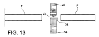
この時点で、図13に示されるように、調整ツール36は、予め決められた位置に到達するまで、チューブの長軸に向かって径方向に移動される。図示する実施例では、切断装置と調整装置の両方に一つだけの駆動ユニットが設けられている。その結果、切断ツール24は、チューブの長軸に向かって、径方向に移動される。しかし、二つのツールが別々に移動する場合、調整処理の間、邪魔にならないように、それはスタート位置に静止させてもよい。
At this point, as shown in FIG. 13, the
その後、チューブ片Pは、調整ツール(図14)を動作するための使用位置に到達するまで、調整ツール36に向けて軸方向に移動される。
The tube piece P is then moved axially towards the
このとき、ロータ18が回転される(上述の先の工程では、ロータは途切れることなく回転を維持することが可能であるが、実際の調整処理中に使用される速度とは異なる速度で回転することが可能である。)。また、チューブ片P(図15)の内径を拡大するために、同時に、調整ツール36は、径方向外側に向けて予め決められた位置まで(又は、予め決められた力で)適当に移動される。上述のように、調整ツール36は、ここで示す実施例のように、チューブの塑性変形によって調整を行うように配置してもよいし、チップ除去によって調整を行うように配置してもよい。
At this time, the
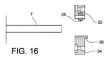
最後に、図16に示されるように、調整処理が終了すると、新たに処理されたチューブ片が取り外され、調整ツール36が、開示位置に到達するまで、チューブTの径方向寸法の外側に移動される。
Finally, as shown in FIG. 16, once the adjustment process is complete, the newly processed tube piece is removed and the
以上の説明から明らかなように、本発明に係る装置によれば、チューブの切断直後に調整処理を行うことができるので、サイクルタイムを最小に減らすことができる。実際、チューブの調整だけのために、新たに切断されたチューブ片を別のワークステーションに移動する必要がない。また、調整ツールと切断ツールを同じ装置に一体化したため、設備が簡単になり、製造コストや必要なスペースが減る。 As is clear from the above description, the device according to the present invention allows the adjustment process to be performed immediately after the tube is cut, thereby reducing the cycle time to a minimum. In fact, it is not necessary to move the newly cut tube pieces to a separate workstation just to adjust the tube. Furthermore, the integration of the adjustment tool and the cutting tool in the same device simplifies the installation, reduces the manufacturing costs and the space required.
当然、特許請求の範囲に記載した発明の範囲から逸脱することなく、本発明の原理を変更せずに、非限定的実施例としてのみ記載し説明した実施例に関して、実施例及び細部を変更してもよい。 Naturally, modifications of the embodiments and details may be made with respect to those described and illustrated only as non-limiting examples, without departing from the scope of the invention as defined in the claims and without altering the principles of the invention.
Claims (6)
開口孔(20)を有し、切断される前記チューブ(T)が前記開口孔(20)を介して前記チューブ(T)の長軸に沿って移動されるロータ(18)であって、前記ロータ(18)は使用中前記装置(14)に供給される前記チューブ(T)の前記長軸に一致する第1回転軸(x1)を中心に回転するように駆動可能である、ロータ(18)と、
前記第1回転軸(x1)の径方向に移動可能なように前記ロータ(18)に搭載された第1支持体(22)と、前記第1支持体(22)によって運ばれる切断ツール(24)を含む切断装置(22,24)と、
前記ロータ(18)に搭載されて前記ロータ(18)上を径方向に移動可能な第2支持体(34)と、前記第2支持体(34)によって運ばれる調整ツール(36)とを有し、
前記装置は、前記調整ツール(36)が径方向外側に移動されて、前記チューブの一部(P)の内径を拡大し、
前記第1支持体(22)と前記第2支持体(34)は、互いに分離され、同じ径方向(y)に沿って移動可能に前記ロータ(18)に設けられており、
前記第1支持体(22)及び前記第2支持体(34)の両方と対になり、前記径方向(y)に沿って、前記第1回転軸(x1)に対して対称に、前記第1支持体(22)と前記第2支持体(34)を移動する一つの駆動装置(32)を有する、装置。 A device for cutting and adjusting a tube (T) into a ring shape,
a rotor (18) having an aperture (20) through which the tube (T) to be cut is moved along a longitudinal axis of the tube (T), the rotor (18) being drivable to rotate about a first axis of rotation (x1) which coincides with the longitudinal axis of the tube (T) being fed into the device (14) during use;
a first support (22) mounted on the rotor (18) so as to be movable in a radial direction of the first rotation axis (x1); and a cutting device (22, 24) including a cutting tool (24) carried by the first support (22);
a second support (34) mounted on the rotor (18) and radially movable on the rotor (18), and an adjustment tool (36) carried by the second support (34);
The apparatus further comprises: the adjustment tool (36) being moved radially outward to enlarge the inner diameter of the portion (P) of the tube;
the first support (22) and the second support (34) are separated from each other and are provided on the rotor (18) so as to be movable along the same radial direction (y);
the device having one drive device (32) that is paired with both the first support (22) and the second support (34) and moves the first support (22) and the second support (34) along the radial direction (y) symmetrically with respect to the first rotation axis (x1).
前記ロータ(18)を回転しながら、前記切断ツール(24)によって前記チューブ(T)から前記チューブ(T)の一部(P)を切断し、
前記チューブ(T)の一部(P)を軸方向に移動して、前記チューブ(T)の一部(P)を前記チューブ(T)の残余部から遠ざけ、
前記調整ツール(36)を、前記調整ツールが前記チューブ(T)の径方向の予め決められた位置に到達するまで、前記チューブ(T)の長軸に向かって径方向に移動し、
前記チューブ(T)の一部(P)を前記調整ツール(36)に向けて軸方向に移動し、
前記ロータ(18)を回転しながら、前記調整ツール(36)を径方向外側に移動して、前記チューブ(T)の一部(P)の前記内径を拡大する、請求項5に記載のチューブ加工機。 The tube processing machine includes:
While rotating the rotor (18), cutting a portion (P) of the tube (T) from the tube (T) with the cutting tool (24);
Axial moving a portion (P) of the tube (T) away from a remainder of the tube (T);
moving said adjustment tool (36) radially towards the longitudinal axis of said tube (T) until said adjustment tool reaches a predetermined radial position of said tube (T);
Axial movement of a portion (P) of the tube (T) towards the adjustment tool (36);
6. The tube processing machine of claim 5, wherein the adjustment tool (36) is moved radially outward while the rotor (18) is rotated to enlarge the inner diameter of the portion (P) of the tube (T).
Applications Claiming Priority (3)
| Application Number | Priority Date | Filing Date | Title |
|---|---|---|---|
| IT102019000002815 | 2019-02-27 | ||
| IT102019000002815A IT201900002815A1 (en) | 2019-02-27 | 2019-02-27 | Equipment for orbital cutting and calibration of pipes |
| PCT/IB2020/051621 WO2020174409A1 (en) | 2019-02-27 | 2020-02-26 | Apparatus for the orbital cutting and calibration of tubes |
Publications (2)
| Publication Number | Publication Date |
|---|---|
| JP2022521629A JP2022521629A (en) | 2022-04-11 |
| JP7528107B2 true JP7528107B2 (en) | 2024-08-05 |
Family
ID=66641315
Family Applications (1)
| Application Number | Title | Priority Date | Filing Date |
|---|---|---|---|
| JP2021549954A Active JP7528107B2 (en) | 2019-02-27 | 2020-02-26 | Orbital cutting device and tube adjustment device |
Country Status (11)
| Country | Link |
|---|---|
| US (1) | US12576438B2 (en) |
| EP (1) | EP3930948A1 (en) |
| JP (1) | JP7528107B2 (en) |
| KR (1) | KR102918663B1 (en) |
| CN (1) | CN113490567B (en) |
| BR (1) | BR112021016874A2 (en) |
| CA (1) | CA3130229A1 (en) |
| IT (1) | IT201900002815A1 (en) |
| MX (1) | MX2021010175A (en) |
| TW (1) | TWI840517B (en) |
| WO (1) | WO2020174409A1 (en) |
Families Citing this family (2)
| Publication number | Priority date | Publication date | Assignee | Title |
|---|---|---|---|---|
| TWI878012B (en) * | 2024-01-29 | 2025-03-21 | 全利機械股份有限公司 | Hollow coil object cutting mechanism and method |
| CN121018406B (en) * | 2025-10-30 | 2025-12-26 | 台州职业技术学院 | Multi-line cutting line speed and line length high-precision calibration control method |
Citations (1)
| Publication number | Priority date | Publication date | Assignee | Title |
|---|---|---|---|---|
| US20160121406A1 (en) | 2014-10-29 | 2016-05-05 | Illinois Tool Works Inc. | Interchangeable cutting inserts and methods associated with the same |
Family Cites Families (18)
| Publication number | Priority date | Publication date | Assignee | Title |
|---|---|---|---|---|
| US4430913A (en) * | 1982-03-23 | 1984-02-14 | Kaiser Steel Corporation | Cut-off and face machine |
| JPS60136827U (en) * | 1984-02-20 | 1985-09-11 | カヤバ工業株式会社 | Pipe expansion wrench |
| US5531370A (en) * | 1990-08-14 | 1996-07-02 | Rohrberg; Roderick G. | High-precision sizing, cutting and welding tool system for specialty aerospace alloys |
| JP2838447B2 (en) * | 1991-03-20 | 1998-12-16 | 株式会社オスガーマシン | Pipe cutting method and pipe cutter |
| JPH0751922A (en) * | 1993-08-06 | 1995-02-28 | Kouhou Koki:Kk | Pipe cutting machine and pipe cutting method |
| US5549024A (en) * | 1995-01-30 | 1996-08-27 | Ricci; Donato L. | Clamshell pipe lathe having improved bearing arrangement |
| DE19907740B4 (en) * | 1999-02-23 | 2008-02-14 | Volkswagen Ag | A method for separating a pipe section from a cylindrical tube, as well as a separating device for carrying out the method |
| US8186249B2 (en) * | 2008-06-30 | 2012-05-29 | Pratt & Whitney Canada Corp. | Three point turning machine |
| ITRN20120016A1 (en) * | 2012-03-23 | 2013-09-24 | Sica Spa | METHOD AND CUTTING EQUIPMENT OF A TUBE IN THERMOPLASTIC MATERIAL. |
| KR101531573B1 (en) * | 2012-08-10 | 2015-06-25 | 삼성중공업 주식회사 | Pipe cutting and beveling apparatus |
| ITPD20130128A1 (en) * | 2013-05-10 | 2014-11-11 | Ingotools Srl | TOOL FOR DEBURRING AND CALIBRATION OF TUBES AND TUBULAR COMPONENTS WITH LONGITUDINAL DEVELOPMENT IN GENERAL |
| KR101636758B1 (en) * | 2014-05-30 | 2016-07-06 | 디씨에스이엔지 주식회사 | A orbital type pipe cutting/beveling machine for the cutting tool can be freely controlled in rotation plate using the RPM ratio |
| DE102015212968B4 (en) * | 2014-07-17 | 2023-06-22 | Sms Group Gmbh | Method and device for calibrating the ends of metal pipes |
| DE102014112437A1 (en) * | 2014-08-29 | 2016-03-03 | Propress Gmbh | Calibration and chamfering tool |
| KR101549822B1 (en) * | 2014-10-13 | 2015-09-04 | 최인성 | A orbital type cutting machine for can be freely controlled of plural cutting tool in rotation plate using the RPM ratio |
| US10065246B2 (en) * | 2015-04-13 | 2018-09-04 | Illinois Tool Works Inc. | Laser line generator tool for a pipe machining apparatus |
| CN206382618U (en) * | 2016-12-07 | 2017-08-08 | 江西金盈新材料科技股份有限公司 | A kind of stainless steel pressure pipeline cutter device |
| TWM550184U (en) * | 2017-05-23 | 2017-10-11 | Hao Thing Electricity Machinery Co Ltd | Transmission mechanism of pipe processing machine |
-
2019
- 2019-02-27 IT IT102019000002815A patent/IT201900002815A1/en unknown
-
2020
- 2020-02-26 TW TW109106173A patent/TWI840517B/en not_active IP Right Cessation
- 2020-02-26 BR BR112021016874A patent/BR112021016874A2/en active Search and Examination
- 2020-02-26 CN CN202080016357.2A patent/CN113490567B/en active Active
- 2020-02-26 JP JP2021549954A patent/JP7528107B2/en active Active
- 2020-02-26 CA CA3130229A patent/CA3130229A1/en active Pending
- 2020-02-26 EP EP20708203.3A patent/EP3930948A1/en active Pending
- 2020-02-26 MX MX2021010175A patent/MX2021010175A/en unknown
- 2020-02-26 US US17/434,260 patent/US12576438B2/en active Active
- 2020-02-26 KR KR1020217030012A patent/KR102918663B1/en active Active
- 2020-02-26 WO PCT/IB2020/051621 patent/WO2020174409A1/en not_active Ceased
Patent Citations (1)
| Publication number | Priority date | Publication date | Assignee | Title |
|---|---|---|---|---|
| US20160121406A1 (en) | 2014-10-29 | 2016-05-05 | Illinois Tool Works Inc. | Interchangeable cutting inserts and methods associated with the same |
Also Published As
| Publication number | Publication date |
|---|---|
| BR112021016874A2 (en) | 2021-11-03 |
| KR20210127753A (en) | 2021-10-22 |
| MX2021010175A (en) | 2021-09-14 |
| EP3930948A1 (en) | 2022-01-05 |
| TWI840517B (en) | 2024-05-01 |
| KR102918663B1 (en) | 2026-01-26 |
| TW202045275A (en) | 2020-12-16 |
| IT201900002815A1 (en) | 2020-08-27 |
| CN113490567B (en) | 2024-12-31 |
| US20220134403A1 (en) | 2022-05-05 |
| CA3130229A1 (en) | 2020-09-03 |
| WO2020174409A1 (en) | 2020-09-03 |
| JP2022521629A (en) | 2022-04-11 |
| CN113490567A (en) | 2021-10-08 |
| US12576438B2 (en) | 2026-03-17 |
Similar Documents
| Publication | Publication Date | Title |
|---|---|---|
| CN103781570B (en) | Method for producing springs and spring machine for carrying out the method | |
| JP7528107B2 (en) | Orbital cutting device and tube adjustment device | |
| JP2003509181A (en) | Manufacture of closed-end tubes for surgical devices | |
| KR20150136485A (en) | Polygon machining device and polygon machining method | |
| WO2018179009A1 (en) | Pipe clamping and cutting apparatus for cnc machine | |
| US12005600B2 (en) | Method and apparatus for cutting a pipe made from thermoplastic material | |
| EP3653326A1 (en) | Thread cutting device and thread cutting method | |
| JP3397696B2 (en) | Spring forming method | |
| CN218425628U (en) | Cylinder sleeve machining equipment | |
| JP2001321868A (en) | Bent rod forming method, and forming device used therefor | |
| EP3210685B1 (en) | Machine and method for bending a tubular product | |
| JP2838447B2 (en) | Pipe cutting method and pipe cutter | |
| JPH04354613A (en) | Method and device for pipe cutting | |
| CN107639421A (en) | A kind of discharge process equipment and its processing technology | |
| JP2006110714A (en) | Cutting method of pipe and cutting device of pipe | |
| US6619162B1 (en) | Device for cutting tubes | |
| JP2002273536A (en) | COILING APPARATUS AND METHOD AND CORE METAL OF COILING APPARATUS | |
| JP4857266B2 (en) | Step of forming a ring | |
| RU2815023C1 (en) | Bending machine | |
| US20230134903A1 (en) | Bending machine | |
| JP2005288624A (en) | Metal pipe sizing device | |
| JPH07613U (en) | Auger cutting equipment | |
| GB2358603A (en) | Method and apparatus for cutting a length of tube |
Legal Events
| Date | Code | Title | Description |
|---|---|---|---|
| A521 | Request for written amendment filed |
Free format text: JAPANESE INTERMEDIATE CODE: A523 Effective date: 20230106 |
|
| A621 | Written request for application examination |
Free format text: JAPANESE INTERMEDIATE CODE: A621 Effective date: 20230106 |
|
| A131 | Notification of reasons for refusal |
Free format text: JAPANESE INTERMEDIATE CODE: A131 Effective date: 20240130 |
|
| A977 | Report on retrieval |
Free format text: JAPANESE INTERMEDIATE CODE: A971007 Effective date: 20240131 |
|
| A521 | Request for written amendment filed |
Free format text: JAPANESE INTERMEDIATE CODE: A523 Effective date: 20240412 |
|
| A131 | Notification of reasons for refusal |
Free format text: JAPANESE INTERMEDIATE CODE: A131 Effective date: 20240604 |
|
| A521 | Request for written amendment filed |
Free format text: JAPANESE INTERMEDIATE CODE: A523 Effective date: 20240613 |
|
| TRDD | Decision of grant or rejection written | ||
| A01 | Written decision to grant a patent or to grant a registration (utility model) |
Free format text: JAPANESE INTERMEDIATE CODE: A01 Effective date: 20240709 |
|
| A61 | First payment of annual fees (during grant procedure) |
Free format text: JAPANESE INTERMEDIATE CODE: A61 Effective date: 20240724 |
|
| R150 | Certificate of patent or registration of utility model |
Ref document number: 7528107 Country of ref document: JP Free format text: JAPANESE INTERMEDIATE CODE: R150 |