JP7531464B2 - Vehicle side door - Google Patents
Vehicle side door Download PDFInfo
- Publication number
- JP7531464B2 JP7531464B2 JP2021145640A JP2021145640A JP7531464B2 JP 7531464 B2 JP7531464 B2 JP 7531464B2 JP 2021145640 A JP2021145640 A JP 2021145640A JP 2021145640 A JP2021145640 A JP 2021145640A JP 7531464 B2 JP7531464 B2 JP 7531464B2
- Authority
- JP
- Japan
- Prior art keywords
- panel
- bent
- connection portion
- vehicle
- bracket
- Prior art date
- Legal status (The legal status is an assumption and is not a legal conclusion. Google has not performed a legal analysis and makes no representation as to the accuracy of the status listed.)
- Active
Links
- 239000000463 material Substances 0.000 claims description 29
- 229910000838 Al alloy Inorganic materials 0.000 claims description 14
- 239000010959 steel Substances 0.000 claims description 13
- 229910000831 Steel Inorganic materials 0.000 claims description 12
- 230000003014 reinforcing effect Effects 0.000 claims description 8
- 230000002093 peripheral effect Effects 0.000 claims description 7
- 230000001154 acute effect Effects 0.000 claims description 5
- 238000005452 bending Methods 0.000 description 9
- 238000004519 manufacturing process Methods 0.000 description 4
- 239000000853 adhesive Substances 0.000 description 2
- 230000001070 adhesive effect Effects 0.000 description 2
- 239000011347 resin Substances 0.000 description 2
- 229920005989 resin Polymers 0.000 description 2
- 229910000851 Alloy steel Inorganic materials 0.000 description 1
- 230000000295 complement effect Effects 0.000 description 1
- 239000011521 glass Substances 0.000 description 1
- 229910052751 metal Inorganic materials 0.000 description 1
- 239000002184 metal Substances 0.000 description 1
- 238000000034 method Methods 0.000 description 1
- 238000012986 modification Methods 0.000 description 1
- 230000004048 modification Effects 0.000 description 1
Images



Landscapes
- Body Structure For Vehicles (AREA)
Description
本発明は、車両用サイドドアに関する。 The present invention relates to a vehicle side door.
車両用サイドドアは、インナパネルおよびアウタパネルからなるパネルセットの内部にドアビームなどの補強部品を配置し、強度を向上させることがある。例えば、特許文献1には、そのような補強構造を有する車両用サイドドアが開示されている。
Vehicle side doors may have reinforcing parts such as door beams placed inside a panel set consisting of an inner panel and an outer panel to improve their strength. For example,
車両用サイドドアでは、重量やコスト等の制約から、パネルセットとドアビームが異なる材質からなる場合がある。この場合、両者の材質の線膨張係数が異なることに起因して昇温時の伸びに違いが生じ、熱ひずみが生じるおそれがある。 In vehicle side doors, the panel set and the door beam may be made of different materials due to weight, cost, and other constraints. In such cases, the difference in linear expansion coefficient between the two materials can cause differences in their elongation when heated, which can lead to thermal strain.
本発明は、線膨張係数が異なる材質からなるパネルセットとドアビームを含む車両用サイドドアにおいて、熱ひずみを抑制することを課題とする。 The objective of the present invention is to suppress thermal strain in a vehicle side door that includes a panel set and a door beam made of materials with different linear expansion coefficients.
本発明は、
車体の外板を構成するアウタパネル、および、前記アウタパネルと対向して前記アウタパネルよりも車両幅方向の内側に配置されるインナパネルを有するパネルセットと、
前記インナパネルと前記アウタパネルとの間に配置されて車両前後方向に延びるドアビーム、および、前記ドアビームと前記インナパネルを接続するブラケットを有する補強部品と
を備え、
前記ブラケットは、前記インナパネルと接続される第1接続部と、前記ドアビームと接続される第2接続部と、前記第1接続部と前記第2接続部との間の中間部とを有し、
前記中間部は、折れ曲がった少なくとも1つの屈曲部を有し、
前記パネルセットの材質の線膨張係数と前記ドアビームの材質の線膨張係数は、異なっている、車両用サイドドアを提供する。
The present invention relates to
a panel set including an outer panel constituting an outer panel of a vehicle body and an inner panel facing the outer panel and disposed more inwardly than the outer panel in a vehicle width direction;
a door beam disposed between the inner panel and the outer panel and extending in a vehicle front-rear direction, and a reinforcing part having a bracket connecting the door beam and the inner panel,
The bracket has a first connection portion connected to the inner panel, a second connection portion connected to the door beam, and an intermediate portion between the first connection portion and the second connection portion,
The intermediate portion has at least one bent portion,
The linear expansion coefficient of the material of the panel set is different from that of the material of the door beam.
この構成によれば、パネルセットの材質の線膨張係数とドアビームの材質の線膨張係数は異なっているため、昇温時の伸びに違いが生じる。しかし、ブラケットの中間部に屈曲部が設けられているため、中間部は屈曲部を起点に撓むことができる。即ち、ブラケットは、柔軟性を有している。このように柔軟性を有するブラケットを使用することにより、パネルセットとドアビームの伸びの違いを吸収でき、即ち熱ひずみを抑制できる。 With this configuration, the linear expansion coefficient of the material of the panel set and the linear expansion coefficient of the material of the door beam are different, so there is a difference in the expansion when the temperature rises. However, because a bent portion is provided in the middle of the bracket, the middle portion can bend starting from the bent portion. In other words, the bracket has flexibility. By using a flexible bracket in this way, the difference in expansion between the panel set and the door beam can be absorbed, which means that thermal strain can be suppressed.
前記少なくとも1つの屈曲部は、前記第2接続部よりも車両幅方向の内側に配置されてもよい。また、前記少なくとも1つの屈曲部は、前記第2接続部よりも車両幅方向の外側に配置されてもよい。 The at least one bent portion may be disposed on the inner side of the second connection portion in the vehicle width direction. The at least one bent portion may be disposed on the outer side of the second connection portion in the vehicle width direction.
これらの構成によれば、屈曲部の位置を規定することにより、所望のレイアウトを実現できる。特に、屈曲部を第2接続部よりも車両幅方向の内側に配置すると、中間部を長く確保できる傾向があり、より大きな柔軟性を確保できる。 With these configurations, the desired layout can be achieved by specifying the position of the bend. In particular, if the bend is positioned on the inside of the second connection in the vehicle width direction, the middle section tends to be longer, ensuring greater flexibility.
前記少なくとも1つの屈曲部は、複数の屈曲部を含んでもよい。 The at least one bend may include multiple bends.
この構成によれば、1つの屈曲部が設けられている場合に比べて、屈曲の自由度が向上するため、ブラケットが柔軟に変形できる。 This configuration allows for greater flexibility in bending compared to when only one bending section is provided, allowing the bracket to deform flexibly.
前記複数の屈曲部の1つは、前記第2接続部よりも車両幅方向の内側に配置されてもよく、
前記複数の屈曲部の別の1つは、前記第2接続部よりも車両幅方向の外側に配置されてもよい。
One of the plurality of bent portions may be disposed inward in a vehicle width direction relative to the second connection portion,
Another one of the plurality of bent portions may be disposed outboard of the second connection portion in the vehicle width direction.
この構成によれば、中間部の長さを長く確保できるとともに様々に屈曲させることができるためブラケットの柔軟性を向上できる。 This configuration allows the middle section to be long and can be bent in various ways, improving the flexibility of the bracket.
前記パネルセットは、アルミニウム合金製であってもよく、
前記ドアビームは、鋼鉄製であってもよい。
The panel set may be made of an aluminum alloy;
The door beam may be made of steel.
この構成によれば、アルミニウム合金および鋼鉄は車両用サイドドアの材質として実用的であるため、実用的な車両用サイドドアを構成できる。また、仮に、柔軟性を有していないブラケットを使用すると、製造工程において昇温時に線膨張係数の大きいパネルセットが伸びようとするとき、線膨張係数の小さいドアビームが抵抗となる。そのため、ブラケットには引っ張りの力がかかり、パネルセットの変形が拘束されて熱ひずみが発生する。しかし、上記構成のように柔軟性を有するブラケットを使用することで、ブラケットが伸び、パネルセットの変形が拘束されることを抑制でき、熱ひずみを抑制できる。 With this configuration, since aluminum alloy and steel are practical materials for vehicle side doors, a practical vehicle side door can be constructed. Furthermore, if an inflexible bracket were used, the door beam, which has a small linear expansion coefficient, would resist the panel set, which has a large linear expansion coefficient, as it tries to stretch when the temperature rises during the manufacturing process. This would result in a tensile force being applied to the bracket, which would restrict the deformation of the panel set and cause thermal strain. However, by using a flexible bracket as in the above configuration, the bracket can be prevented from stretching and the deformation of the panel set from being restricted, thereby suppressing thermal strain.
前記パネルセットは、鋼鉄製であってもよく、
前記ドアビームは、アルミニウム合金製であってもよい。
The panel set may be made of steel;
The door beam may be made of an aluminum alloy.
この構成によれば、アルミニウム合金および鋼鉄は車両用サイドドアの材質として実用的であるため、実用的な車両用サイドドアを構成できる。また、仮に、柔軟性を有していないブラケットを使用すると、製造工程において昇温時に線膨張係数の大きいドアビームが伸びようとするとき、線膨張係数の小さいパネルセットが抵抗となる。そのため、ブラケットには圧縮の力がかかり、ドアビームの変形が拘束されて熱ひずみが発生する。しかし、上記構成のように柔軟性を有するブラケットを使用することで、ブラケットが撓み、ドアビームの変形が拘束されることを抑制でき、熱ひずみを抑制できる。 With this configuration, since aluminum alloy and steel are practical materials for vehicle side doors, a practical vehicle side door can be constructed. Furthermore, if an inflexible bracket were used, when the door beam, which has a large linear expansion coefficient, tries to expand when the temperature rises during the manufacturing process, the panel set, which has a small linear expansion coefficient, acts as a resistance. As a result, a compressive force is applied to the bracket, which restricts the deformation of the door beam and generates thermal strain. However, by using a flexible bracket as in the above configuration, it is possible to prevent the bracket from bending and the deformation of the door beam from being restricted, thereby suppressing thermal strain.
前記パネルセットの材質の線膨張係数は、前記ドアビームの材質の線膨張係数の2倍以上または半分以下であってもよい。 The linear expansion coefficient of the material of the panel set may be more than twice or less than half the linear expansion coefficient of the material of the door beam.
この構成によれば、上記熱ひずみの問題が顕在化しやすい材料の組み合わせに対して上記構成が一層有効に機能し得る。 This configuration makes it even more effective for combinations of materials that tend to cause the thermal distortion problem.
本発明によれば、線膨張係数が異なる材質からなるパネルセットとドアビームを含む車両用サイドドアにおいて、熱ひずみを抑制できる。 According to the present invention, it is possible to suppress thermal strain in a vehicle side door that includes a panel set and a door beam made of materials with different linear expansion coefficients.
以下、添付図面を参照して本発明の実施形態を説明する。 The following describes an embodiment of the present invention with reference to the attached drawings.
(第1実施形態)
図1は、本発明の第1実施形態にかかる車両用サイドドア1(以降、単にサイドドア1ともいう。)の斜視図を示している。矢印FR、矢印UP、矢印INは、それぞれ車両前後方向の前側、車両上下方向の上側、および車両幅方向の内側を示している。これらは、以降の図でも同様の表記で示す。
First Embodiment
1 shows a perspective view of a vehicle side door 1 (hereinafter, simply referred to as side door 1) according to a first embodiment of the present invention. Arrows FR, UP, and IN indicate the front side in the vehicle longitudinal direction, the upper side in the vehicle vertical direction, and the inside in the vehicle width direction, respectively. These will be indicated in the same manner in the subsequent figures.
図示のサイドドア1は、図示しない車体の側部を構成する。なお、車体の種類については特に限定されない。
The
サイドドア1は、上部のウインドウフレーム10と、下部のパネルセット20とを含んでいる。
The
ウインドウフレーム10には、図示しないドアガラスが昇降可能に配置される。
A door glass (not shown) is arranged in the
パネルセット20は、図示しない車体の外板を構成するアウタパネル21と、アウタパネル21と対向してアウタパネル21よりも車両幅方向の内側に配置されるインナパネル22とを有している。
The
図2は、図1のサイドドア1の分解斜視図を示している。
Figure 2 shows an exploded perspective view of the
本実施形態では、アウタパネル21は、概ね平坦な板状であり、周縁部21aにおいてインナパネル22の周縁部22aを挟み込むようにヘミング加工が施されている(詳細は図3参照)。インナパネル22は周縁部22aに対して中央部22bが車幅方向内側へ凹んだ形状を有し、周縁部22aにおいてアウタパネル21と接合されている。
In this embodiment, the
インナパネル22とアウタパネル21との間には、補強部品30が配置されている。補強部品30は、車両前後方向に延びるドアビーム31と、ドアビーム31とインナパネル22を接続するブラケット40とを有している。
A reinforcing
ドアビーム31は、パネルセット20を補強する部材である。本実施形態では、ドアビームは、断面円形のパイプ状である。ドアビーム31は、ブラケット40と合わせて、サイドドア1の車両前後方向の概ね全体にわたって延びている。インナパネル22の車両前後方向の後部には、ドアビーム31と相補的な形状を有する載置部23が設けられている。例えば、載置部23は、インナパネル22とは別体の樹脂部材であり、インナパネル22にねじ止めされている。ドアビーム31の車両前後方向の後端31aは、載置部23に載置および固定されている。ドアビーム31の車両前後方向の前端31bは、ブラケット40に接続されている。
The
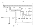
図3は、第1実施形態におけるブラケット40付近の模式的な断面図を示している。図3では、サイドドア1の車両上下方向に垂直な断面が示されている。
Figure 3 shows a schematic cross-sectional view of the
本実施形態では、ブラケット40は、折り曲げられた板状である。ブラケット40は、インナパネル22と接続される第1接続部41と、ドアビーム31と接続される第2接続部42と、第1接続部41と第2接続部42との間の中間部43とを有している。インナパネル22および第1接続部41は、リベット等を用いた機械的接合、溶融接合又は接着剤を用いた接合がなされている。同様に、ドアビーム31および第2接続部42は、リベット等を用いた機械的接合、溶融接合又は接着剤を用いた接合がなされている。後述の通り、サイドドア1の各部の材質は種々選択可能であり、選択した材料に応じて接合方法を適宜選択可能である。
In this embodiment, the
第1接続部41と中間部43と境界は、折り曲げによって形成された稜線部41aによって規定される。なお、稜線部41aは第1接続部41に含まれる。同様に、第2接続部42と中間部43と境界は、折り曲げによって形成された稜線部42aによって規定される。なお、稜線部42aは、第2接続部42に含まれる。
The boundary between the
本実施形態では、中間部43は、折れ曲がった2つの屈曲部44a,44b(これらを区別なく単に屈曲部44ともいう。)を有している。なお、稜線部41a,42aは、折れ曲がった形状を有しているが、前述の通り中間部43に設けられたものではないため、屈曲部44とは異なる。
In this embodiment, the
本実施形態では、2つの屈曲部44a,44bは、第2接続部42よりも車両幅方向の内側に配置されている。2つの屈曲部44a,44bは、ともに車両幅方向の内側に向かって凸形状を構成するように概ね90度折り曲げられている。
In this embodiment, the two
以上の構成を有する本実施形態のサイドドア1の各部の材質について例示する。
The following are examples of materials used for each part of the
パネルセット20は、例えばアルミニウム合金製である。即ち、インナパネル22およびアウタパネル21は、ともにアルミニウム合金製である。アルミニウム合金の線膨張係数は、約2.36×10⁻⁵である。
The panel set 20 is made of, for example, an aluminum alloy, that is, both the
ドアビーム31は、例えば鋼鉄製である。鋼鉄の線膨張係数は、約1.1×10⁻⁵である。
The
本実施形態では、パネルセット20の材質(アルミニウム合金)の線膨張係数は、ドアビーム31の材質(鋼鉄)の線膨張係数の2倍以上となっている。 In this embodiment, the linear expansion coefficient of the material of the panel set 20 (aluminum alloy) is more than twice the linear expansion coefficient of the material of the door beam 31 (steel).
本実施形態では、ブラケット40の材質は、鋼鉄またはアルミニウム合金などの金属製であるが、これに限定されず、例えば樹脂製であってもよい。
In this embodiment, the material of the
本実施形態によれば、パネルセット20の材質の線膨張係数とドアビーム31の材質の線膨張係数は異なっているため、昇温時の伸びに違いが生じる。しかし、ブラケット40の中間部43に屈曲部44が設けられているため、中間部43は屈曲部44を起点に撓むことができる。即ち、ブラケット40は、柔軟性を有している。このように柔軟性を有するブラケット40を使用することにより、パネルセット20とドアビーム31の伸びの違いを吸収でき、即ち熱ひずみを抑制できる。
According to this embodiment, the linear expansion coefficient of the material of the panel set 20 and the linear expansion coefficient of the material of the
また、第1接続部を第2接続部42よりも車両幅方向の外側に配置するとともに屈曲部44を第2接続部42よりも車両幅方向の内側に配置しているため、中間部43を長く確保でき、より大きな柔軟性を確保できる。
In addition, because the first connection portion is positioned outside the
また、2つの屈曲部44a,44bが設けられているため、1つのみ屈曲部が設けられている場合に比べて、屈曲の自由度が向上する。よって、ブラケット40が柔軟に変形できる。
In addition, because two bending
また、パネルセット20がアルミニウム合金製であり、ドアビーム31が鋼鉄製であるため、実用的なサイドドア1を構成できる。仮に、柔軟性を有していないブラケット40を使用すると、製造工程において昇温時に線膨張係数の大きいパネルセット20が伸びようとするとき、線膨張係数の小さいドアビーム31が抵抗となる。そのため、ブラケット40には引っ張りの力がかかり、パネルセット20の変形が拘束されて熱ひずみが発生する。しかし、本実施形態のように柔軟性を有するブラケット40を使用することで、ブラケット40が伸び、パネルセット20の変形が拘束されることを抑制でき、熱ひずみを抑制できる。
In addition, since the panel set 20 is made of aluminum alloy and the
また、アルミニウム合金の線膨張係数は鋼鉄の線膨張係数の2倍以上であるため、何らの工夫をしない場合には熱ひずみの問題が顕在化しやすい。従って、本実施形態の柔軟性を有するブラケット40が一層有効に機能し得る。
In addition, the linear expansion coefficient of aluminum alloys is more than twice that of steel, so unless some special measures are taken, the problem of thermal strain is likely to become apparent. Therefore, the
代替的には、パネルセット20がアルミニウム合金製であり、ドアビーム31が鋼鉄製であってもよい。この場合、パネルセット20の材質の線膨張係数は、ドアビーム31の材質の線膨張係数の半分以下となる。
Alternatively, the panel set 20 may be made of an aluminum alloy and the
パネルセット20が鋼鉄製であり、ドアビーム31がアルミニウム合金製である場合、実用的な車両用サイドドアを構成できる。このとき、仮に、柔軟性を有していないブラケット40を使用すると、製造工程において昇温時に線膨張係数の大きいドアビームが伸びようとするとき、線膨張係数の小さいパネルセットが抵抗となる。そのため、ブラケット40には圧縮の力がかかり、ドアビーム31の変形が拘束されて熱ひずみが発生する。しかし、本実施形態のように柔軟性を有するブラケット40を使用することで、ブラケット40が撓み、ドアビーム31の変形が拘束されることを抑制でき、熱ひずみを抑制できる。
When the panel set 20 is made of steel and the
図4は、第1実施形態の第1変形例におけるブラケット40付近の模式的な断面図を示している。
Figure 4 shows a schematic cross-sectional view of the vicinity of
図4の例では、中間部43は、1つの屈曲部44c(単に屈曲部44ともいう。)を有している。屈曲部44cは、車両幅方向の内側に向かって凸に鋭角に折り曲げられている。
In the example shown in FIG. 4, the
図5は、第1実施形態の第2変形例におけるブラケット40付近の模式的な断面図を示している。
Figure 5 shows a schematic cross-sectional view of the vicinity of
図5の例では、中間部43は、4つの屈曲部44d~44g(これらを区別なく単に屈曲部44ともいう。)を有している。4つの屈曲部44d~44gのそれぞれは、車両幅方向の内側に向かって凸に鈍角に折り曲げられている。
In the example shown in FIG. 5, the
第1変形例および第2変形例に示すように、中間部43の屈曲部44の数の数や形状は特に限定されず、少なくとも1つ以上設けられていればよい。
As shown in the first and second modified examples, the number and shape of the
(第2実施形態)
図6に示す第2実施形態の車両用サイドドア1は、ブラケット40の形状が第1実施形態と異なる。これに関する構成以外は、第1実施形態と実質的に同じである。従って、第1実施形態にて示した部分については説明を省略する場合がある。
Second Embodiment
The
本実施形態では、中間部43は1つの屈曲部44h(単に屈曲部44ともいう。)を有している。屈曲部44hは、第2接続部42よりも車両幅方向の外側に配置されている。屈曲部44hは、車両幅方向の外側に向かって凸に鈍角に折り曲げられている。図示の例では、屈曲部44hは、車両前後方向において中間部43の概ね中央に形成されている。
In this embodiment, the
図7は、第2実施形態の第1変形例におけるブラケット40付近の模式的な断面図を示している。
Figure 7 shows a schematic cross-sectional view of the vicinity of
図7の例では、中間部43は、3つの屈曲部44i~44k(これらを区別なく単に屈曲部44ともいう。)を有している。屈曲部44i,44jは、第2接続部42と車両幅方向に揃えられている。屈曲部44i,44jは、ともに車両幅方向の内側に向かって凸に鈍角に折り曲げられている。また、屈曲部44kは、第2接続部42よりも車両幅方向の外側に配置されている。屈曲部44kは、車両幅方向の外側に向かって凸に鋭角に折り曲げられている。
In the example of FIG. 7, the
図8は、第2実施形態の第2変形例におけるブラケット40付近の模式的な断面図を示している。
Figure 8 shows a schematic cross-sectional view of the vicinity of
図8の例では、中間部43は、2つの屈曲部44l,44m(これらを区別なく単に屈曲部44ともいう。)を有している。2つの屈曲部44l,44mは、車両幅方向の位置を揃えられ、ともに第2接続部42よりも車両幅方向の外側に配置されている。屈曲部44lは、車両幅方向の内側に向かって凸に鈍角に折り曲げられている。また、屈曲部44mは、車両幅方向の外側に向かって凸に鈍角に折り曲げられている。
In the example of FIG. 8, the
図9は、第2実施形態の第3変形例におけるブラケット40付近の模式的な断面図を示している。
Figure 9 shows a schematic cross-sectional view of the vicinity of
図9の例では、中間部43は、4つの屈曲部44n~44q(これらを区別なく単に屈曲部44ともいう。)を有している。屈曲部44n,44oの車幅方向の位置は、揃えられている。また、屈曲部44p,44qの車幅方向の位置は、揃えられている。4つの屈曲部44n~44qのいずれも第2接続部42よりも車両幅方向の外側に配置されている。屈曲部44n,44pは、車両幅方向の内側に向かって凸に鈍角に折り曲げられている。屈曲部44o,44qは、車両幅方向の外側に向かって凸に鈍角に折り曲げられている。
In the example of FIG. 9, the
本実施形態においても、第1~3変形例に示すように、中間部43の屈曲部44の数や形状は特に限定されず、少なくとも1つ以上であればよい。
In this embodiment, as shown in the first to third modified examples, the number and shape of the
(第3実施形態)
図10に示す第3実施形態の車両用サイドドア1は、ブラケット40の形状が第1,2実施形態と異なる。これに関する構成以外は、第1,2実施形態と実質的に同じである。従って、第1,2実施形態にて示した部分については説明を省略する場合がある。
Third Embodiment
The
本実施形態では、中間部43は、3つの屈曲部44r~44tが設けられている。(これらを区別なく単に屈曲部44ともいう。)を有している。屈曲部44r,44sは、第2接続部42よりも車両幅方向の外側に配置されている。屈曲部44tは、第2接続部42よりも車両幅方向の内側に配置されている。屈曲部44rは、車両幅方向の内側に向かって凸に鈍角に折り曲げられている。屈曲部44sは、車両幅方向の外側に向かって凸に鈍角に折り曲げられている。屈曲部44tは、車両幅方向の内側に向かって凸に鋭角に折り曲げられている。
In this embodiment, the
本実施形態によれば、中間部43の長さを長く確保できるとともに様々に屈曲させることができるため、ブラケットの柔軟性を向上できる。また、本実施形態では、第2接続部42よりも車両幅方向の外側および内側に屈曲部44が設けられていればよく、その数や形状は特に限定されない。
According to this embodiment, the
以上より、本発明の具体的な実施形態およびその変形例について説明したが、本発明は上記形態に限定されるものではなく、この発明の範囲内で種々変更して実施することができる。例えば、個々の実施形態の内容を適宜組み合わせたものを、この発明の一実施形態としてもよい。 The above describes specific embodiments of the present invention and their variations, but the present invention is not limited to the above embodiments and can be implemented with various modifications within the scope of the invention. For example, an appropriate combination of the contents of each embodiment may be one embodiment of the present invention.
1 車両用サイドドア(サイドドア)
10 ウインドウフレーム
20 パネルセット
21 アウタパネル
21a 周縁部
22 インナパネル
22a 周縁部
22b 中央部
23 載置部
30 補強部品
31 ドアビーム
31a 後端
31b 前端
40 ブラケット
41 第1接続部
41a 稜線部
42 第2接続部
42a 稜線部
43 中間部
44,44a~44t 屈曲部
1. Vehicle side door (side door)
REFERENCE SIGNS
Claims (10)
前記インナパネルと前記アウタパネルとの間に配置されて車両前後方向に延びるドアビーム、および、前記ドアビームと前記インナパネルを車両方向の前端で接続するブラケットを有する補強部品と
を備え、
周縁部において前記アウタパネルと前記インナパネルとは接合しており、
前記ブラケットは、前記アウタパネルとは異なる位置で前記インナパネルと接続される第1接続部と、前記ドアビームと接続される第2接続部と、前記第1接続部と前記第2接続部との間の中間部とを有し、
前記第1接続部と前記第2接続部はそれぞれ前記中間部との境界に稜線部を有し、
前記中間部は、折れ曲がった少なくとも1つの屈曲部を有し、
前記パネルセットの材質の線膨張係数と前記ドアビームの材質の線膨張係数は、異なっている、車両用サイドドア。 a panel set including an outer panel constituting an outer panel of a vehicle body and an inner panel facing the outer panel and disposed more inwardly than the outer panel in a vehicle width direction;
a door beam disposed between the inner panel and the outer panel and extending in a vehicle front-rear direction; and a reinforcing part having a bracket connecting the door beam and the inner panel at a front end in the vehicle direction ,
The outer panel and the inner panel are joined at a peripheral portion,
the bracket has a first connection portion connected to the inner panel at a position different from the outer panel , a second connection portion connected to the door beam, and an intermediate portion between the first connection portion and the second connection portion,
the first connection portion and the second connection portion each have a ridge portion at a boundary with the intermediate portion,
The intermediate portion has at least one bent portion,
A vehicle side door, wherein the linear expansion coefficient of the material of the panel set is different from the linear expansion coefficient of the material of the door beam.
前記複数の屈曲部の別の1つは、前記第2接続部よりも車両幅方向の外側に配置されている、請求項4に記載の車両用サイドドア。 One of the plurality of bent portions is disposed on the inner side of the second connection portion in a vehicle width direction,
The vehicle side door according to claim 4 , wherein another one of the plurality of bent portions is disposed outboard of the second connection portion in a vehicle width direction.
前記ドアビームは、鋼鉄製である、請求項1から請求項5のいずれか1項に記載の車両用サイドドア。 the panel set is made of an aluminum alloy;
6. The vehicle side door according to claim 1, wherein the door beam is made of steel.
前記ドアビームは、アルミニウム合金製である、請求項1から請求項5のいずれか1項に記載の車両用サイドドア。 the panel set is made of steel;
The vehicle side door according to any one of claims 1 to 5, wherein the door beam is made of an aluminum alloy.
前記インナパネルと前記アウタパネルとの間に配置されて車両前後方向に延びるドアビーム、および、前記ドアビームと前記インナパネルを接続するブラケットを有する補強部品とa door beam disposed between the inner panel and the outer panel and extending in a vehicle front-rear direction, and a reinforcing part having a bracket connecting the door beam and the inner panel;
を備え、Equipped with
前記ブラケットは、前記インナパネルと接続される第1接続部と、前記ドアビームと接続される第2接続部と、前記第1接続部と前記第2接続部との間の中間部とを有し、The bracket has a first connection portion connected to the inner panel, a second connection portion connected to the door beam, and an intermediate portion between the first connection portion and the second connection portion,
前記中間部は、折れ曲がった少なくとも1つの屈曲部を有し、The intermediate portion has at least one bent portion,
前記屈曲部の少なくとも1つは鋭角に折れ曲がっており、At least one of the bent portions is bent at an acute angle,
前記パネルセットの材質の線膨張係数と前記ドアビームの材質の線膨張係数は、異なっている、車両用サイドドア。A vehicle side door, wherein the linear expansion coefficient of the material of the panel set is different from the linear expansion coefficient of the material of the door beam.
Priority Applications (1)
| Application Number | Priority Date | Filing Date | Title |
|---|---|---|---|
| JP2021145640A JP7531464B2 (en) | 2021-09-07 | 2021-09-07 | Vehicle side door |
Applications Claiming Priority (1)
| Application Number | Priority Date | Filing Date | Title |
|---|---|---|---|
| JP2021145640A JP7531464B2 (en) | 2021-09-07 | 2021-09-07 | Vehicle side door |
Publications (2)
| Publication Number | Publication Date |
|---|---|
| JP2023038759A JP2023038759A (en) | 2023-03-17 |
| JP7531464B2 true JP7531464B2 (en) | 2024-08-09 |
Family
ID=85514657
Family Applications (1)
| Application Number | Title | Priority Date | Filing Date |
|---|---|---|---|
| JP2021145640A Active JP7531464B2 (en) | 2021-09-07 | 2021-09-07 | Vehicle side door |
Country Status (1)
| Country | Link |
|---|---|
| JP (1) | JP7531464B2 (en) |
Citations (7)
| Publication number | Priority date | Publication date | Assignee | Title |
|---|---|---|---|---|
| JP2007269118A (en) | 2006-03-30 | 2007-10-18 | Kobe Steel Ltd | Closed cross-section structural member made of aluminum or aluminum alloy |
| JP2007326532A (en) | 2006-06-09 | 2007-12-20 | Toyota Motor Corp | Vehicle door structure |
| JP2010023572A (en) | 2008-07-16 | 2010-02-04 | Toyota Motor Corp | Vehicle door structure |
| JP2011110945A (en) | 2009-11-24 | 2011-06-09 | Fuji Heavy Ind Ltd | Energy absorbing beam for vehicle and door structure for vehicle |
| JP2014162301A (en) | 2013-02-22 | 2014-09-08 | Toyota Motor Corp | Vehicle door structure |
| JP2018114936A (en) | 2017-01-20 | 2018-07-26 | トヨタ自動車株式会社 | Vehicle door |
| JP2019156384A (en) | 2017-11-01 | 2019-09-19 | Jfeスチール株式会社 | Reinforcement structure of vehicle door panel part and reinforcement method |
-
2021
- 2021-09-07 JP JP2021145640A patent/JP7531464B2/en active Active
Patent Citations (7)
| Publication number | Priority date | Publication date | Assignee | Title |
|---|---|---|---|---|
| JP2007269118A (en) | 2006-03-30 | 2007-10-18 | Kobe Steel Ltd | Closed cross-section structural member made of aluminum or aluminum alloy |
| JP2007326532A (en) | 2006-06-09 | 2007-12-20 | Toyota Motor Corp | Vehicle door structure |
| JP2010023572A (en) | 2008-07-16 | 2010-02-04 | Toyota Motor Corp | Vehicle door structure |
| JP2011110945A (en) | 2009-11-24 | 2011-06-09 | Fuji Heavy Ind Ltd | Energy absorbing beam for vehicle and door structure for vehicle |
| JP2014162301A (en) | 2013-02-22 | 2014-09-08 | Toyota Motor Corp | Vehicle door structure |
| JP2018114936A (en) | 2017-01-20 | 2018-07-26 | トヨタ自動車株式会社 | Vehicle door |
| JP2019156384A (en) | 2017-11-01 | 2019-09-19 | Jfeスチール株式会社 | Reinforcement structure of vehicle door panel part and reinforcement method |
Also Published As
| Publication number | Publication date |
|---|---|
| JP2023038759A (en) | 2023-03-17 |
Similar Documents
| Publication | Publication Date | Title |
|---|---|---|
| US8424961B2 (en) | Aluminum roof panel for attachment to supporting steel vehicle body members | |
| US20160090124A1 (en) | Vehicle body rear structure | |
| JP6781657B2 (en) | Vehicle trunk lid panel | |
| US10167021B2 (en) | Vehicular resin panel structure and luggage door | |
| US10988005B2 (en) | Vehicle door structure and method for manufacturing the same | |
| JP7531464B2 (en) | Vehicle side door | |
| JP4115981B2 (en) | Stereo camera mounting structure for vehicles | |
| US9327770B2 (en) | Center pillar reinforcement unit for vehicle | |
| US12370870B2 (en) | Door impact beam | |
| JP7397025B2 (en) | Vehicle rear structure | |
| KR102206726B1 (en) | Bus frame apparatus | |
| CN109987152A (en) | Body construction | |
| CN104470794A (en) | Motor vehicles including additional reinforcements capable of guiding structural deformation of the central pillar in the event of a side impact | |
| JP6984525B2 (en) | Outer panel stiffening structure and stiffening outer panel | |
| JP6952743B2 (en) | Body floor tunnel structure | |
| JP6343298B2 (en) | Body structure | |
| WO2013105439A1 (en) | Vehicle | |
| JP7194358B2 (en) | Vehicle roof panel reinforcement structure | |
| JP2018020643A (en) | Wheel house structure | |
| JP6792795B2 (en) | Side body structure of automobile | |
| JP7388202B2 (en) | Vehicle side wall structure | |
| JP2018052372A (en) | Reinforcement structure of vehicle body rear part | |
| JP7755480B2 (en) | Axle case structure | |
| KR20210037044A (en) | Bus frame module | |
| JP2002225651A (en) | Extrusion hollow section for bending |
Legal Events
| Date | Code | Title | Description |
|---|---|---|---|
| A621 | Written request for application examination |
Free format text: JAPANESE INTERMEDIATE CODE: A621 Effective date: 20230901 |
|
| A977 | Report on retrieval |
Free format text: JAPANESE INTERMEDIATE CODE: A971007 Effective date: 20240222 |
|
| A131 | Notification of reasons for refusal |
Free format text: JAPANESE INTERMEDIATE CODE: A131 Effective date: 20240227 |
|
| A521 | Request for written amendment filed |
Free format text: JAPANESE INTERMEDIATE CODE: A523 Effective date: 20240426 |
|
| TRDD | Decision of grant or rejection written | ||
| A01 | Written decision to grant a patent or to grant a registration (utility model) |
Free format text: JAPANESE INTERMEDIATE CODE: A01 Effective date: 20240723 |
|
| A61 | First payment of annual fees (during grant procedure) |
Free format text: JAPANESE INTERMEDIATE CODE: A61 Effective date: 20240730 |
|
| R150 | Certificate of patent or registration of utility model |
Ref document number: 7531464 Country of ref document: JP Free format text: JAPANESE INTERMEDIATE CODE: R150 |