JP7532043B2 - Parking Assistance Device - Google Patents
Parking Assistance Device Download PDFInfo
- Publication number
- JP7532043B2 JP7532043B2 JP2020023853A JP2020023853A JP7532043B2 JP 7532043 B2 JP7532043 B2 JP 7532043B2 JP 2020023853 A JP2020023853 A JP 2020023853A JP 2020023853 A JP2020023853 A JP 2020023853A JP 7532043 B2 JP7532043 B2 JP 7532043B2
- Authority
- JP
- Japan
- Prior art keywords
- vehicle
- parking
- parking position
- curb
- assistance device
- Prior art date
- Legal status (The legal status is an assumption and is not a legal conclusion. Google has not performed a legal analysis and makes no representation as to the accuracy of the status listed.)
- Active
Links
Images




Landscapes
- Control Of Driving Devices And Active Controlling Of Vehicle (AREA)
- Traffic Control Systems (AREA)
Description
本開示は、駐車支援装置に関する。 This disclosure relates to a parking assistance device.
従来から駐車支援装置に関する発明が知られている(下記特許文献1を参照)。特許文献1に記載された駐車支援装置は、経路算出部と、移動制御部と、検知部と、を備えている(同文献、要約等を参照)。前記経路算出部は、車両がすでに移動していた経路を含む道上の車両の位置から縦列駐車の第1の目標位置までの移動経路であって、当該第1の目標位置に進ませる前に当該車両を切り返させる第1の切り返し予定位置を含めた移動経路を算出する。前記移動制御部は、前記移動経路に基づいた操舵制御で、前記車両を前記第1の目標位置に移動させる。前記検知部は、前記車両の進行方向に存在する物体を検知する。 Inventions relating to parking assistance devices have been known for some time (see Patent Document 1 below). The parking assistance device described in Patent Document 1 includes a path calculation unit, a movement control unit, and a detection unit (see the document, abstract, etc.). The path calculation unit calculates a movement path from a vehicle position on a road including a path the vehicle has already traveled to a first target position for parallel parking, the movement path including a first planned turning position at which the vehicle will turn before proceeding to the first target position. The movement control unit moves the vehicle to the first target position by steering control based on the movement path. The detection unit detects an object that exists in the traveling direction of the vehicle.
前記移動制御部は、さらに、前記移動経路に従って前記車両を移動させ、前記第1の切り返し予定位置まで移動する前に、前記検知部が物体を検知した場合に、当該物体に接触する前の第1の位置で前記車両を切り返させる。その後、前記移動制御部は、前記第1の切り返し予定位置と、前記第1の切り返し予定位置より前記道側の前記第1の位置と、の位置関係に基づいて、前記第1の切り返し予定位置から前記第1の目標位置までの移動経路を修正する。そして、前記移動制御部は、修正された移動経路に従って、前記第1の目標位置より前記道側にずれた第2の目標位置まで前記車両を移動させる。 The movement control unit further moves the vehicle according to the movement path, and, if the detection unit detects an object before the vehicle moves to the first planned turning position, causes the vehicle to turn at a first position before contacting the object. The movement control unit then corrects the movement path from the first planned turning position to the first target position based on the positional relationship between the first planned turning position and the first position on the road side of the first planned turning position. The movement control unit then moves the vehicle according to the corrected movement path to a second target position shifted toward the road side from the first target position.
上記従来の駐車支援装置において、移動制御部は、最初に算出された第1の切り返し予定位置と、この第1の切り返し予定位置よりも道側で、新たに検知された物体に接触する前の切り返し位置である第1の位置との位置関係に基づいて移動経路を修正する。そのため、移動制御部が修正された移動経路に従って第1の目標位置より道側にずれた第2の目標位置まで車両を移動させると、車両が道側にはみ出し、車両の乗員が不自然さや危険を感じるおそれがある。 In the above conventional parking assistance device, the movement control unit corrects the movement path based on the positional relationship between the first planned turning position that was initially calculated and the first position, which is the turning position before contacting a newly detected object on the road side of the first planned turning position. Therefore, when the movement control unit moves the vehicle to a second target position that is shifted toward the road side from the first target position according to the corrected movement path, the vehicle may stray toward the road side, causing the vehicle occupants to feel unnatural or unsafe.
本開示は、車両をより適切な位置に駐車させることが可能な駐車支援装置を提供する。 This disclosure provides a parking assistance device that can park a vehicle in a more appropriate position.
本開示の一態様は、車両の駐車予定位置と走行経路とを算出する駐車支援装置であって、前記車両に搭載された外界センサから前記車両の周囲の外界情報を取得し、前記外界情報に基づいて物体を認識し、前記物体の位置に基づいて前記駐車予定位置を算出し、前記車両の制御開始位置から前記駐車予定位置までの前記走行経路を算出し、前記車両が前記走行経路に沿って移動を開始した後に前記外界情報に基づいて障害物が認識された場合に、該障害物の位置に基づいて前記駐車予定位置の修正可能範囲を算出するとともに前記修正可能範囲に含まれる修正駐車位置までの前記走行経路を算出する、駐車支援装置である。 One aspect of the present disclosure is a parking assistance device that calculates a planned parking position and a driving route for a vehicle, and that acquires external environment information around the vehicle from an external environment sensor mounted on the vehicle, recognizes an object based on the external environment information, calculates the planned parking position based on the position of the object, calculates the driving route from a control start position of the vehicle to the planned parking position, and, if an obstacle is recognized based on the external environment information after the vehicle starts moving along the driving route, calculates a correctable range of the planned parking position based on the position of the obstacle, and calculates the driving route to a corrected parking position included in the correctable range.
本開示によれば、車両をより適切な位置に駐車させることが可能な駐車支援装置を提供することができる。 This disclosure provides a parking assistance device that can park a vehicle in a more appropriate position.
以下、図面を参照して本開示に係る駐車支援装置の実施形態を説明する。 Below, an embodiment of the parking assistance device according to the present disclosure will be described with reference to the drawings.
図1は、本実施形態に係る駐車支援装置10を搭載した車両1の構成を概略的に示すブロック図である。本実施形態の駐車支援装置10は、たとえば、乗用車、トラック、またはバスなど車両1に搭載され、車両1の駐車支援を行うための電子制御装置(ECU)である。 Figure 1 is a block diagram showing the schematic configuration of a vehicle 1 equipped with a parking assistance device 10 according to this embodiment. The parking assistance device 10 according to this embodiment is an electronic control unit (ECU) that is installed in the vehicle 1, such as a passenger car, truck, or bus, and that provides parking assistance for the vehicle 1.
図1に示す例において、駐車支援装置10が搭載された車両1は、たとえば、車輪2と、車両センサ3と、外界センサ4と、ステアリングホイール5と、電動パワーステアリング装置6と、車両制御装置7と、表示装置8と、を備えている。また、図1に示す例では、たとえば、車両センサ3と、外界センサ4と、車両制御装置7と、駐車支援装置10と、図示を省略する各種のアクチュエータとによって、車両1の駐車支援システムが構成されている。
In the example shown in FIG. 1, the vehicle 1 equipped with the parking assistance device 10 includes, for example, wheels 2, a vehicle sensor 3, an external sensor 4, a steering wheel 5, an electric power steering device 6, a
車輪2は、たとえば、左右の前輪と、左右の後輪とを含む。左右の前輪である車輪2は、たとえば、電動パワーステアリング装置6により、図示を省略する操舵機構を介して転舵される操舵輪である。左右の後輪である車輪2は、たとえば、図示を省略するエンジンまたはモータなどの駆動源により、図示を省略する動力伝達機構を介して駆動される駆動輪である。なお、左右の前輪である車輪2が駆動輪であってもよい。 The wheels 2 include, for example, left and right front wheels and left and right rear wheels. The left and right front wheels 2 are steered wheels that are steered by, for example, an electric power steering device 6 via a steering mechanism (not shown). The left and right rear wheels 2 are drive wheels that are driven by, for example, a drive source such as an engine or a motor (not shown) via a power transmission mechanism (not shown). Note that the left and right front wheels 2 may be drive wheels.
車両センサ3は、たとえば、車両1の速度、加速度、角速度、位置情報などの車両情報Ivを検知するセンサである。車両センサ3は、たとえば、車輪速センサ3aを含む。車輪速センサ3aは、たとえば、左右の前輪である車輪2と左右の後輪である車輪2のそれぞれの回転速度rsを検知して、駐車支援装置10へ出力する。車両センサ3は、たとえば、図示を省略する加速度センサ、角速度センサ、および全球測位衛星システム(GNSS)などを含む。 The vehicle sensor 3 is a sensor that detects vehicle information Iv such as the speed, acceleration, angular velocity, and position information of the vehicle 1. The vehicle sensor 3 includes, for example, a wheel speed sensor 3a. The wheel speed sensor 3a detects, for example, the rotational speeds rs of the left and right front wheels 2 and the left and right rear wheels 2, and outputs the rotational speeds rs to the parking assistance device 10. The vehicle sensor 3 includes, for example, an acceleration sensor, an angular velocity sensor, and a global navigation satellite system (GNSS), which are not shown.
外界センサ4は、車両1の周囲の外界情報Ieを検知するセンサである。外界センサ4は、たとえば、カメラ4aと、超音波センサ4bとを含む。また、外界センサ4は、たとえば、LiDARなど、カメラ4aおよび超音波センサ4b以外のセンサを含んでもよい。 The external sensor 4 is a sensor that detects external information Ie around the vehicle 1. The external sensor 4 includes, for example, a camera 4a and an ultrasonic sensor 4b. The external sensor 4 may also include sensors other than the camera 4a and the ultrasonic sensor 4b, such as LiDAR.
カメラ4aは、たとえば、単眼カメラまたはステレオカメラであり、車両1の前部、後部および左右の側部に、車両1の周囲の物体、路面、道路標示などを撮影することができるように、適切な角度および画角で設置されている。カメラ4aは、車両1の周囲の外界情報Ieとして、画像情報gを駐車支援装置10へ出力する。 Camera 4a is, for example, a monocular camera or a stereo camera, and is installed at the front, rear, and left and right sides of vehicle 1 at an appropriate angle and field of view so as to capture images of objects, road surfaces, road markings, and the like around vehicle 1. Camera 4a outputs image information g to parking assistance device 10 as external environment information Ie around vehicle 1.
超音波センサ4bは、たとえば、車両1の前部の正面部、左右コーナ部、および左右側部、ならびに、車両1の後部の正面部、左右コーナ部、および左右側部に設けられている。超音波センサ4bは、超音波を送信波として送信し、車両1の周囲の物体に反射された反射波を受信することで、車両1の周囲の物体までの距離dを検知し、外界情報Ieとして、駐車支援装置10へ出力する。 The ultrasonic sensor 4b is provided, for example, on the front, left and right corners, and left and right sides of the front of the vehicle 1, and on the front, left and right corners, and left and right sides of the rear of the vehicle 1. The ultrasonic sensor 4b transmits ultrasonic waves as a transmission wave and receives a reflected wave reflected by an object around the vehicle 1 to detect the distance d to the object around the vehicle 1, and outputs it to the parking assistance device 10 as external environment information Ie.
ステアリングホイール5は、車両1の運転者のステアリング操作に応じた操舵角で回転する。また、ステアリングホイール5は、たとえば、図示を省略する操舵アクチュータによって自動的に操作される。 The steering wheel 5 rotates at a steering angle according to the steering operation of the driver of the vehicle 1. In addition, the steering wheel 5 is automatically operated, for example, by a steering actuator (not shown).
電動パワーステアリング装置6は、運転者によるステアリングホイール5の操作を補助して、ステアリングホイール5の操舵角に応じて操舵輪である車輪2を転舵させる。電動パワーステアリング装置6は、たとえば、図示を省略する操舵角センサ、転舵補助モータ、および操舵ECUを備えている。 The electric power steering device 6 assists the driver in operating the steering wheel 5 and steers the wheels 2, which are the steered wheels, according to the steering angle of the steering wheel 5. The electric power steering device 6 includes, for example, a steering angle sensor, a steering assist motor, and a steering ECU, all of which are not shown.
操舵角センサは、ステアリングホイール5の操舵角θを検知して、操舵ECU、車両制御装置7、および駐車支援装置10へ出力する。転舵補助モータは、図示を省略する操舵機構を介して操舵輪である車輪2を転舵させる操舵トルクを補助する。操舵用ECUは、操舵用の電子制御装置であり、ステアリングの操舵角に応じて転舵補助モータを制御し、操舵トルクを制御する。
The steering angle sensor detects the steering angle θ of the steering wheel 5 and outputs it to the steering ECU, the
車両制御装置7は、駐車支援装置10から入力される車両1の走行経路Rpおよび駐車予定位置Lpなどに基づいて、車両1の自動駐車または駐車支援を実行するECUである。より具体的には、車両制御装置7は、たとえば、図示を省略する中央処理装置(CPU)、ROMやRAMなどの記憶装置、データの入出力を行う入出力回路、およびタイマーなどを備えたマイクロコントローラまたはファームウェアによって構成することができる。
The
車両制御装置7は、たとえば、記憶装置に記憶されたプログラムをCPUによって実行し、車両1に搭載された図示を省略する各種のアクチュエータを制御することで、車両1の操作を自動的に行い、または、運転者による車両1の操作を支援する。ここでの車両1の操作は、たとえば、ステアリング操作、シフト操作、アクセル操作、ブレーキ操作のすべて、または、少なくとも一つである。
The
表示装置8は、たとえば、車両1の運転席の近傍に設置された液晶表示装置、有機EL表示装置、またはヘッドアップディスプレイなどによって構成され、車両1の運転者に各種の情報を表示する。表示装置8は、たとえば、カメラ4aによって撮影されて駐車支援装置10によって処理された車両1の周囲の画像を表示する。また、表示装置8は、たとえば、駐車支援装置10によって算出された駐車予定位置Lp、走行経路Rpなどの情報を表示する。表示装置8は、たとえば、タッチパネル、キーボード、スイッチ、または音声入力装置などの情報入力装置を備え、運転者の操作によって入力された各種の情報Iiを、駐車支援装置10へ出力する。 The display device 8 is, for example, a liquid crystal display device, an organic EL display device, or a head-up display installed near the driver's seat of the vehicle 1, and displays various information to the driver of the vehicle 1. The display device 8 displays, for example, an image of the surroundings of the vehicle 1 captured by the camera 4a and processed by the parking assistance device 10. The display device 8 also displays, for example, information such as the planned parking position Lp and the driving route Rp calculated by the parking assistance device 10. The display device 8 is equipped with an information input device such as a touch panel, a keyboard, a switch, or a voice input device, and outputs various information Ii input by the driver's operation to the parking assistance device 10.
以下、本実施形態の駐車支援装置10の構成を、図2および図3を参照して詳細に説明する。図2は、本実施形態の駐車支援装置10の構成を概略的に示すブロック図である。図3は、本実施形態の駐車支援装置10の各機能を説明する機能ブロック図である。 The configuration of the parking assistance device 10 of this embodiment will be described in detail below with reference to Figures 2 and 3. Figure 2 is a block diagram that shows a schematic configuration of the parking assistance device 10 of this embodiment. Figure 3 is a functional block diagram that explains each function of the parking assistance device 10 of this embodiment.
本実施形態の駐車支援装置10は、車両1の駐車予定位置Lpと走行経路Rpとを算出する装置である。駐車支援装置10は、たとえば、マイクロコントローラによって構成されたECUである。駐車支援装置10は、図2に示すように、たとえば、回路基板11とCPU12とを備えている。 The parking assistance device 10 of this embodiment is a device that calculates a planned parking position Lp and a driving route Rp of the vehicle 1. The parking assistance device 10 is, for example, an ECU configured with a microcontroller. As shown in FIG. 2, the parking assistance device 10 includes, for example, a circuit board 11 and a CPU 12.
回路基板11は、たとえば、A/D変換器11aと、RAMやROMなどの記憶装置11bと、図示を省略する入出力回路とを含む。駐車支援装置10は、たとえば、回路基板11の入出力回路を介して、図1に示すように、車両センサ3、外界センサ4、電動パワーステアリング装置6、および車両制御装置7に接続されている。駐車支援装置10は、たとえば、外界センサ4から出力された外界情報Ieと、車両センサ3から出力された車両情報Ivとを入力とする。
The circuit board 11 includes, for example, an A/D converter 11a, a storage device 11b such as a RAM or ROM, and an input/output circuit (not shown). The parking assistance device 10 is connected to the vehicle sensor 3, the external sensor 4, the electric power steering device 6, and the
より具体的には、駐車支援装置10は、たとえば、カメラ4aから出力された画像情報gと、超音波センサ4bから出力された車両1の周囲の物体までの方向および距離dとを入力とする。また、駐車支援装置10は、たとえば、車輪速センサ3aから出力された車輪2の回転速度rsと、電動パワーステアリング装置6の操舵角センサから出力されたステアリングホイール5の操舵角θとを入力とする。 More specifically, the parking assistance device 10 receives, for example, image information g output from the camera 4a and the direction and distance d to objects around the vehicle 1 output from the ultrasonic sensor 4b. The parking assistance device 10 also receives, for example, the rotation speed rs of the wheels 2 output from the wheel speed sensor 3a and the steering angle θ of the steering wheel 5 output from the steering angle sensor of the electric power steering device 6.
CPU12は、たとえば、図示を省略する入出力回路を介して回路基板11に接続され、回路基板11に搭載されたA/D変換器11a、記憶装置11bとの間で情報の授受を行う。また、CPU12は、記憶装置11bに記憶されたプログラムを実行することで、図示を省略する入出力回路を介して駐車支援装置10に入力された各種の情報を取得して、図4に示すような各種の処理を実行する。 The CPU 12 is connected to the circuit board 11, for example, via an input/output circuit (not shown), and transmits and receives information between the A/D converter 11a and the memory device 11b mounted on the circuit board 11. The CPU 12 also executes a program stored in the memory device 11b to acquire various information input to the parking assistance device 10 via the input/output circuit (not shown), and executes various processes as shown in FIG. 4.
図3に示すように、本実施形態の駐車支援装置10は、たとえば、位置推定機能F11と、演算解析機能F12と、経路演算機能F13と、を備えている。図3に示す駐車支援装置10の各機能は、たとえば、CPU12が記憶装置11bに記憶されたプログラムを実行することで実現することができる。 As shown in FIG. 3, the parking assistance device 10 of this embodiment includes, for example, a position estimation function F11, a calculation analysis function F12, and a path calculation function F13. Each function of the parking assistance device 10 shown in FIG. 3 can be realized, for example, by the CPU 12 executing a program stored in the storage device 11b.
以下、駐車支援装置10による処理の一例を説明する。図4は、本実施形態の駐車支援装置10による処理の一例を示すフロー図である。図5は、本実施形態の駐車支援装置10を搭載した車両1が、道路脇の駐車車両V1,V2の間に縦列駐車を行う場面を示す平面図である。 An example of the processing performed by the parking assistance device 10 will be described below. FIG. 4 is a flow diagram showing an example of the processing performed by the parking assistance device 10 of this embodiment. FIG. 5 is a plan view showing a scene in which a vehicle 1 equipped with the parking assistance device 10 of this embodiment performs parallel parking between vehicles V1 and V2 parked on the side of the road.
駐車支援装置10を搭載した車両1の運転者が、たとえば、図5に示すように、手動運転で道路Rを走行しているときに、道路脇の駐車車両V1,V2の間に駐車スペースを見つけて、車両1を駐車するために減速して停車したとする。運転者は、たとえば、表示装置8のタッチパネルを操作して、運転支援を開始するための情報Iiを駐車支援装置10に入力する。 Assuming that the driver of vehicle 1 equipped with parking assistance device 10 is manually driving on road R as shown in FIG. 5, for example, finds a parking space between parked vehicles V1 and V2 on the side of the road, and decelerates and stops vehicle 1 to park it. The driver operates the touch panel of display device 8, for example, to input information Ii for starting driving assistance to parking assistance device 10.
たとえば、表示装置8のタッチパネルを介して入力された運転支援を開始するための情報Iiは、図3に示すように、駐車支援装置10の位置推定機能F11に入力される。これにより、図4に示す駐車支援装置10による処理が開始される。運転者は、たとえば、車両1を手動運転で、駐車スペースの前方の駐車車両V1の側方に移動させ、縦列駐車に適した駐車スペースの斜め前方の位置で停車する。 For example, information Ii for starting driving assistance input via the touch panel of the display device 8 is input to the position estimation function F11 of the parking assistance device 10 as shown in FIG. 3. This starts the processing by the parking assistance device 10 shown in FIG. 4. For example, the driver manually drives the vehicle 1 to the side of the parked vehicle V1 in front of the parking space, and stops the vehicle in a position diagonally forward of the parking space suitable for parallel parking.
この間、駐車支援装置10は、たとえば、位置推定機能F11により、車両1に搭載された車両センサ3から車両1の車両情報Ivを取得して、車両1の位置を推定する処理P1を実行する。より具体的には、処理P1において、位置推定機能F11は、車輪速センサ3aから各々の車輪2の回転速度rsを取得して、車両1の速度を算出する。また、処理P1において、位置推定機能F11は、電動パワーステアリング装置6の操舵角センサから操舵角θを取得して、車両1の進行方向を算出する。 During this time, the parking assistance device 10 executes process P1, for example, by using the position estimation function F11 to acquire vehicle information Iv of the vehicle 1 from the vehicle sensor 3 mounted on the vehicle 1 and estimate the position of the vehicle 1. More specifically, in process P1, the position estimation function F11 acquires the rotation speed rs of each wheel 2 from the wheel speed sensor 3a and calculates the speed of the vehicle 1. Also, in process P1, the position estimation function F11 acquires the steering angle θ from the steering angle sensor of the electric power steering device 6 and calculates the traveling direction of the vehicle 1.
さらに、処理P1において、位置推定機能F11は、車両1の速度と進行方向に基づいて、車両1の座標位置を算出する。なお、位置推定機能F11は、処理P1において、たとえば、GNSSから車両1の座標位置を取得してもよい。位置推定機能F11によって算出または取得された車両1の位置情報は、たとえば、演算解析機能F12および経路演算機能F13に入力される。 Furthermore, in process P1, the position estimation function F11 calculates the coordinate position of the vehicle 1 based on the speed and traveling direction of the vehicle 1. Note that in process P1, the position estimation function F11 may acquire the coordinate position of the vehicle 1 from, for example, the GNSS. The position information of the vehicle 1 calculated or acquired by the position estimation function F11 is input, for example, to the calculation analysis function F12 and the route calculation function F13.
次に、駐車支援装置10は、たとえば、演算解析機能F12により、車両1に搭載された外界センサ4から車両1の周囲の外界情報Ieを取得する処理P2を実行する。より具体的には、処理P2において、演算解析機能F12は、たとえば、カメラ4aから画像情報gを取得するとともに、超音波センサ4bから車両1の周囲の物体までの方向および距離dを取得する。 Next, the parking assistance device 10 executes a process P2 in which, for example, the calculation and analysis function F12 acquires external environment information Ie around the vehicle 1 from the external environment sensor 4 mounted on the vehicle 1. More specifically, in the process P2, the calculation and analysis function F12 acquires, for example, image information g from the camera 4a, and acquires the direction and distance d to objects around the vehicle 1 from the ultrasonic sensor 4b.
次に、駐車支援装置10は、たとえば、演算解析機能F12により、外界情報Ieに基づいて車両1の周囲の物体を認識する処理P3を実行する。より具体的には、処理P3において、演算解析機能F12は、たとえば、画像情報gに対する画像処理を行って車両1の周囲の物体を認識する。 Next, the parking assistance device 10 executes a process P3 in which the calculation and analysis function F12 recognizes objects around the vehicle 1 based on the external environment information Ie. More specifically, in process P3, the calculation and analysis function F12 performs image processing on the image information g to recognize objects around the vehicle 1.
より詳細には、演算解析機能F12は、たとえば、パターンマッチングによって認識した物体の種別を判定するとともに、視差画像に基づいて認識した物体までの距離を算出する。また、演算解析機能F12は、たとえば超音波センサ4bによって得られた物体の方向と距離dに基づいて、物体までの距離を補正する。また、処理P3において、演算解析機能F12は、たとえば、認識した物体の方向および距離に基づいて、物体の位置Poすなわち座標情報を算出する。 More specifically, the calculation and analysis function F12, for example, determines the type of object recognized by pattern matching, and calculates the distance to the recognized object based on the parallax image. The calculation and analysis function F12 also corrects the distance to the object based on the direction and distance d of the object obtained by the ultrasonic sensor 4b, for example. In addition, in process P3, the calculation and analysis function F12 calculates the position Po of the object, i.e., coordinate information, based on the direction and distance of the recognized object, for example.
なお、処理P3において、演算解析機能F12によって認識される物体は、たとえば、車両1の周囲の駐車車両V1,V2、道路R、歩道W、縁石C、道路標示、道路標識、歩行者、その他の障害物を含む。また、処理P3において、演算解析機能F12は、認識した物体の位置Poを、記憶装置11bに記憶させ、車両制御装置7へ出力する。
In process P3, the objects recognized by the calculation and analysis function F12 include, for example, parked vehicles V1 and V2 around the vehicle 1, the road R, the sidewalk W, the curb C, road markings, road signs, pedestrians, and other obstacles. In process P3, the calculation and analysis function F12 stores the position Po of the recognized object in the storage device 11b and outputs it to the
次に、駐車支援装置10は、たとえば、演算解析機能F12により、処理P3で認識された物体の位置Poに基づいて、駐車予定位置Lpを算出する処理P4を実行する。この処理P4において、演算解析機能F12は、たとえば、車両1の全幅、全長、および全高などの仕様に基づく車両1を駐車するのに必要な空間と、道路脇、すなわち道路Rの歩道W側の部分における障害物が存在しない空間とを比較する。 Next, the parking assistance device 10 executes process P4, for example, using the calculation and analysis function F12 to calculate the planned parking position Lp based on the object position Po recognized in process P3. In this process P4, the calculation and analysis function F12 compares the space required to park the vehicle 1 based on the specifications of the vehicle 1, such as the overall width, overall length, and overall height, with the space on the side of the road, i.e., the sidewalk W side of the road R, that is free of obstacles.
さらに、処理P4における上記比較の結果、道路脇に車両1を駐車するのに必要な空間が存在する場合、演算解析機能F12は、その空間に処理P3で認識した物体の位置Poに基づいて駐車予定位置Lpを設定する。このとき、演算解析機能F12は、たとえば、認識された物体と駐車後の車両1との間に、車幅方向および前後方向に、それぞれ所定の間隔を確保するように、駐車予定位置Lpを設定する。 Furthermore, if the result of the above comparison in process P4 indicates that there is a space on the side of the road necessary to park the vehicle 1, the calculation and analysis function F12 sets the planned parking position Lp in that space based on the position Po of the object recognized in process P3. At this time, the calculation and analysis function F12 sets the planned parking position Lp so that, for example, a predetermined distance is secured between the recognized object and the parked vehicle 1 in both the vehicle width direction and the front-rear direction.
図5に示す例において、駐車予定位置Lpは、駐車車両V1,V2の間に一箇所だけが設定されている。しかし、たとえば、駐車車両V1,V2が存在しない場合など、車両1の周囲に広い空間が存在する場合には、車両1の後方に複数の駐車予定位置Lpが設定される場合もある。処理P4において、演算解析機能F12は、たとえば、設定した一または複数の駐車予定位置Lpを、経路演算機能F13へ出力する。 In the example shown in FIG. 5, only one planned parking position Lp is set between parked vehicles V1 and V2. However, if there is a large space around vehicle 1, for example when there are no parked vehicles V1 and V2, multiple planned parking positions Lp may be set behind vehicle 1. In process P4, the calculation and analysis function F12 outputs, for example, the set one or more planned parking positions Lp to the route calculation function F13.
なお、図5に示す例において、駐車支援装置10は、外界情報Ieに基づいて、車両1の左側の駐車車両V1と、車両1の後方の駐車車両V2と、駐車予定位置Lpの歩道W側の縁石Cとを、物体として認識している。また、図5に示す例において、駐車支援装置10は、物体の位置Poである縁石Cの位置を示す座標点列Scを、実際の縁石Cの位置よりも歩道W側の座標点列Scとして認識している。同様に、図5に示す例において、駐車支援装置10は、車両1の後方の物体の位置Poである駐車車両V2の位置を示す座標点列Sbを、実際の駐車車両V2の位置よりも後方の座標点列Sbとして認識している。 In the example shown in FIG. 5, the parking assistance device 10 recognizes the parked vehicle V1 on the left side of the vehicle 1, the parked vehicle V2 behind the vehicle 1, and the curb C on the sidewalk W side of the intended parking position Lp as objects based on the external environment information Ie. Also, in the example shown in FIG. 5, the parking assistance device 10 recognizes the coordinate point sequence Sc indicating the position of the curb C, which is the object position Po, as a coordinate point sequence Sc on the sidewalk W side of the actual position of the curb C. Similarly, in the example shown in FIG. 5, the parking assistance device 10 recognizes the coordinate point sequence Sb indicating the position of the parked vehicle V2, which is the object position Po behind the vehicle 1, as a coordinate point sequence Sb behind the actual position of the parked vehicle V2.
このような物体の実際の位置と、駐車支援装置10によって認識した物体の位置Poすなわち座標点列Scおよび座標点列Sbとのずれは、たとえば、外界センサ4から物体までの距離や角度と、外界センサ4の検出精度との関係によるものである。たとえば、外界センサ4から物体までの距離が遠くなったり、外界センサ4の光軸方向または法線方向と、物体の方向との間の角度が大きくなったりすると、外界センサ4による物体の検出精度は低下する傾向がある。また、図5に示すように、車両1が最初に後退を開始する前の制御開始位置Dpでは、駐車予定位置Lpの奥の縁石Cの一部や、駐車予定位置Lpの後方の駐車車両V2の一部を認識できない場合がある。 Such a deviation between the actual position of the object and the position Po of the object recognized by the parking assistance device 10, i.e., the coordinate point sequence Sc and the coordinate point sequence Sb, is due to, for example, the relationship between the distance or angle from the external sensor 4 to the object and the detection accuracy of the external sensor 4. For example, when the distance from the external sensor 4 to the object increases, or when the angle between the optical axis direction or normal direction of the external sensor 4 and the direction of the object increases, the detection accuracy of the object by the external sensor 4 tends to decrease. Also, as shown in FIG. 5, at the control start position Dp before the vehicle 1 first starts to reverse, it may not be possible to recognize part of the curb C at the back of the intended parking position Lp or part of the parked vehicle V2 behind the intended parking position Lp.
そのため、処理P4において、駐車支援装置10の演算解析機能F12は、たとえば図5に示すように、車両1の駐車予定位置Lpを、適切な位置よりも縁石Cに近い位置に設定したり、駐車車両V2に近い位置に設定したりする場合がある。このように、車両1が最初に後退を開始する前に演算解析機能F12によって設定された駐車予定位置Lpは、駐車支援装置10が実行する後述する処理によって、適切な位置に修正される。 Therefore, in process P4, the calculation and analysis function F12 of the parking assistance device 10 may set the planned parking position Lp of the vehicle 1 to a position closer to the curb C than the appropriate position, or to a position closer to the parked vehicle V2, as shown in FIG. 5, for example. In this way, the planned parking position Lp set by the calculation and analysis function F12 before the vehicle 1 first starts backing up is corrected to an appropriate position by the process executed by the parking assistance device 10, which will be described later.
次に、駐車支援装置10は、たとえば、演算解析機能F12により、処理P4で算出した駐車予定位置Lpを、表示装置8に出力して表示させる処理P5を実行する。この処理P5において、演算解析機能F12は、たとえば、カメラ4aから入力された画像情報gを処理して、車両1の周囲の俯瞰画像を生成し、その俯瞰画像に駐車予定位置Lpを重畳させた画像を、表示装置8に表示させる。 Next, the parking assistance device 10 executes process P5, for example, by using the calculation and analysis function F12 to output the planned parking position Lp calculated in process P4 to the display device 8 for display. In this process P5, the calculation and analysis function F12 processes, for example, the image information g input from the camera 4a to generate an overhead image of the surroundings of the vehicle 1, and displays an image in which the planned parking position Lp is superimposed on the overhead image on the display device 8.
次に、駐車支援装置10は、たとえば、経路演算機能F13により、演算解析機能F12から取得した一または複数の駐車予定位置Lpのいずれかを、運転者が選択したか否かを判定する処理P6を実行する。より具体的には、経路演算機能F13は、たとえば、運転者が表示装置8のタッチパネルまたは音声入力装置を用いて、表示装置8に表示された駐車予定位置Lpを選択する。すると、表示装置8から選択された駐車予定位置Lpの情報Iiが、経路演算機能F13に入力され、経路演算機能F13は、運転者が駐車予定位置Lpを選択した(YES)と判定する。この場合、経路演算機能F13は、次の走行経路Rpを算出する処理P7を実行する。 Next, the parking assistance device 10 executes a process P6 in which, for example, the route calculation function F13 determines whether the driver has selected one or more planned parking positions Lp obtained from the calculation analysis function F12. More specifically, the route calculation function F13, for example, selects the planned parking position Lp displayed on the display device 8 using the touch panel or voice input device of the display device 8. Then, information Ii of the planned parking position Lp selected from the display device 8 is input to the route calculation function F13, and the route calculation function F13 determines that the driver has selected the planned parking position Lp (YES). In this case, the route calculation function F13 executes a process P7 in which the next driving route Rp is calculated.
一方、処理P6において、たとえば、運転者が表示装置8のタッチパネルや音声入力装置を用いて、表示装置8に表示された駐車予定位置Lpをキャンセルすると、表示装置8から駐車支援のキャンセルの情報Iiが経路演算機能F13に入力される。すると、経路演算機能F13は、運転者が駐車予定位置Lpを選択しなかった(NO)と判定する。この場合、駐車支援装置10は、処理P1へ戻り、処理P1から処理P6を繰り返し実行する。 On the other hand, in process P6, for example, if the driver cancels the planned parking position Lp displayed on the display device 8 using the touch panel of the display device 8 or a voice input device, parking assistance cancellation information Ii is input from the display device 8 to the route calculation function F13. Then, the route calculation function F13 determines that the driver did not select the planned parking position Lp (NO). In this case, the parking assistance device 10 returns to process P1 and repeatedly executes processes P1 to P6.
また、前述の処理P4において、演算解析機能F12は、たとえば、車両1の仕様と車両1の周囲の空間との比較の結果、車両1を駐車するのに必要な空間が存在しなかった場合、次の処理P5において、表示装置8に駐車予定位置Lpを表示しない。さらに、次の処理P6において、経路演算機能F13は、たとえば、駐車予定位置Lpが選択されなかった(NO)と判定する。この場合、駐車支援装置10は、処理P1へ戻り、処理P1から処理P6を繰り返し実行する。 In addition, in the above-mentioned process P4, if the calculation and analysis function F12, for example, compares the specifications of the vehicle 1 with the space around the vehicle 1 and determines that there is no space required to park the vehicle 1, then in the next process P5, the planned parking position Lp is not displayed on the display device 8. Furthermore, in the next process P6, the route calculation function F13 determines, for example, that the planned parking position Lp has not been selected (NO). In this case, the parking assistance device 10 returns to process P1 and repeatedly executes processes P1 to P6.
そして、前述のように、処理P6において、経路演算機能F13は、駐車予定位置Lpが選択された(YES)と判定すると、走行経路Rpを算出する処理P7を実行する。この処理P7において、経路演算機能F13は、たとえば、位置推定機能F11から入力された車両1の周囲の物体の位置Poと、演算解析機能F12から入力されて運転者によって選択された駐車予定位置Lpとに基づいて、車両1の走行経路Rpを算出する。 As described above, when the route calculation function F13 determines in process P6 that the planned parking position Lp has been selected (YES), it executes process P7 to calculate the driving route Rp. In this process P7, the route calculation function F13 calculates the driving route Rp of the vehicle 1 based on, for example, the positions Po of objects around the vehicle 1 input from the position estimation function F11 and the planned parking position Lp input from the calculation analysis function F12 and selected by the driver.
より具体的には、処理P7において、経路演算機能F13は、図5に示すように、車両1の停車後に最初に後退を開始する制御開始位置Dpにおける外界情報Ieに基づく座標点列Sa,Sb,Scと運転者が選択した駐車予定位置Lpとを取得する。そして、経路演算機能F13は、座標点列Sa,Sb,Scと車両1の仕様に基づいて、車両1が駐車車両V1,V2および縁石Cに接触しないように、図5に示す車両1の制御開始位置Dpから駐車予定位置Lpまでの走行経路Rpを算出する。また、経路演算機能F13は、算出した走行経路Rpを車両制御装置7へ出力する。
More specifically, in process P7, the route calculation function F13 acquires the coordinate point sequence Sa, Sb, Sc based on the external environment information Ie at the control start position Dp where the vehicle 1 first starts to reverse after stopping, and the planned parking position Lp selected by the driver, as shown in FIG. 5. Then, based on the coordinate point sequence Sa, Sb, Sc and the specifications of the vehicle 1, the route calculation function F13 calculates the driving route Rp from the control start position Dp of the vehicle 1 shown in FIG. 5 to the planned parking position Lp so that the vehicle 1 does not come into contact with the parked vehicles V1, V2 and the curb C. In addition, the route calculation function F13 outputs the calculated driving route Rp to the
次に、図1に示す車両制御装置7によって、図4に示す車両1を移動させる処理P8が実行される。処理P8において、車両制御装置7は、たとえば、図示を省略するブレーキペダルの踏力を検出するセンサにより、車両1の運転者がブレーキペダルを解放したことを検知すると、走行経路Rpに沿って車両1を自動的に走行させる。
Next, the
より具体的には、車両制御装置7は、たとえば、図示を省略する車両1の各種のアクチュエータを制御して、車両1のアクセルペダル、ブレーキペダル、シフトレバー、ステアリングホイール5などを自動的に操作し、車両1を走行経路Rpに沿って走行させる。なお、走行経路Rpが前進経路と後退経路を含む場合には、車両制御装置7は、車両1の前進と後退を切り替える切り返し位置まで、車両1を走行経路Rpに沿って前進させ、切り返し位置で車両1を停車させる、その後、車両制御装置7は、車両1を切り返し位置である制御開始位置Dpから走行経路Rpに沿って最初に後退させる。
More specifically, the
また、処理P8において車両制御装置7が車両1の移動を開始すると、駐車支援装置10は、たとえば演算解析機能F12により、外界情報Ieを取得する処理P9を実行する。次に、駐車支援装置10は、たとえば、演算解析機能F12により、障害物が認識されたか否かを判定する処理P10を実行する。
When the
この処理P10において、演算解析機能F12は、たとえば、外界情報Ieに基づいて物体を認識する。さらに、演算解析機能F12は、車両1が走行経路Rpに沿って移動を開始する前に認識された物体の位置Poである座標点列Sa,Sb,Scとは異なる位置に、車両1に接触する可能性がある障害物が認識されたか否かを判定する。この処理P10において、演算解析機能F12により、車両1に接触する可能性がある障害物が認識されていない(NO)と判定されると、駐車支援装置10は、次の処理P11を実行する。 In this process P10, the calculation and analysis function F12 recognizes an object based on, for example, the external world information Ie. Furthermore, the calculation and analysis function F12 determines whether or not an obstacle that may come into contact with the vehicle 1 has been recognized at a position different from the coordinate point sequence Sa, Sb, Sc, which is the position Po of the object recognized before the vehicle 1 starts moving along the driving path Rp. In this process P10, if the calculation and analysis function F12 determines that an obstacle that may come into contact with the vehicle 1 has not been recognized (NO), the parking assistance device 10 executes the next process P11.
処理P11において、駐車支援装置10は、たとえば、位置推定機能F11により、車両情報Ivに基づいて車両1の位置を推定し、車両1が目標位置である駐車予定位置Lpに到達したか否かを判定する。この処理P11において、位置推定機能F11により、車両1が目標位置に到達していない(NO)と判定されると、駐車支援装置10は、処理P8から処理P11までを繰り返し実行する。 In process P11, the parking assistance device 10, for example, uses the position estimation function F11 to estimate the position of the vehicle 1 based on the vehicle information Iv, and determines whether the vehicle 1 has reached the intended parking position Lp, which is the target position. In this process P11, if the position estimation function F11 determines that the vehicle 1 has not reached the target position (NO), the parking assistance device 10 repeatedly executes processes P8 to P11.
また、処理P10において、演算解析機能F12は、たとえば、車両1に接触する可能性がある障害物が認識された(YES)と判定すると、その障害物の位置を新たな物体の位置Poとして車両制御装置7へ出力する。すると、車両制御装置7は、車両1を障害物の手前で停車させる処理P12を実行する。この処理P12において、車両制御装置7は、たとえば、車輪速センサ3aから取得した車輪2の回転速度rsに基づいて車両1の速度を算出し、車両1の速度に応じた制動距離を算出して、車両1を障害物の手前の停車位置で停車させる。
In addition, in process P10, when the calculation and analysis function F12 determines that an obstacle that may come into contact with the vehicle 1 has been recognized (YES), it outputs the position of the obstacle to the
図6は、図5に示す車両1が、障害物である縁石Cの手前で停止した状態を示す拡大図である。車両1が走行経路Rpに沿って後退して縁石Cおよび駐車車両V2に近づくと、外界センサ4は、縁石Cおよび駐車車両V2の位置Poとして座標点列Sc’および座標点列Sb’をより正確に検知することが可能になる。 Figure 6 is an enlarged view showing the state in which the vehicle 1 shown in Figure 5 has stopped in front of the curb C, which is an obstacle. When the vehicle 1 backs up along the travel path Rp and approaches the curb C and the parked vehicle V2, the external sensor 4 is able to more accurately detect the coordinate point sequence Sc' and the coordinate point sequence Sb' as the positions Po of the curb C and the parked vehicle V2.
その結果、走行経路Rpに沿って移動を開始する前の制御開始位置Dpで設定または認識した駐車予定位置Lpと縁石Cまたは駐車車両V2との間の距離が想定以上に近くなったり、これらが重なったりする。すると、車両1と縁石Cまたは駐車車両V2などの障害物とが接触する可能性が生じたり、車両1の乗降に支障を来したりするおそれがある。このような場合、処理P12において、車両制御装置7は、図6に示すように、障害物である縁石Cや駐車車両V2の手前で、車両1を停車させる。
As a result, the distance between the intended parking position Lp, which was set or recognized at the control start position Dp before starting movement along the travel path Rp, and the curb C or the parked vehicle V2 becomes closer than expected, or they overlap. This may cause the vehicle 1 to come into contact with an obstacle such as the curb C or the parked vehicle V2, or may cause problems when getting on or off the vehicle 1. In such a case, in process P12, the
次に、駐車支援装置10は、たとえば、演算解析機能F12により、駐車予定位置Lpの修正可能範囲Aを算出する処理P13を実行する。ここで、修正可能範囲Aは、駐車予定位置Lpを適切に設定することが可能な範囲である。すなわち、駐車予定位置Lpが修正可能範囲Aに含まれる場合には、駐車予定位置Lpに駐車した車両1と周囲の障害物との間に適切な距離が確保され、運転者が不自然さや危険を感じるほど車両1が道路R側にはみ出すことを防止することができる。 Next, the parking assistance device 10 executes a process P13 to calculate a correctable range A of the planned parking position Lp, for example, by using the calculation analysis function F12. Here, the correctable range A is a range in which the planned parking position Lp can be appropriately set. In other words, when the planned parking position Lp is included in the correctable range A, an appropriate distance is ensured between the vehicle 1 parked at the planned parking position Lp and surrounding obstacles, and it is possible to prevent the vehicle 1 from protruding into the road R to an extent that the driver feels unnatural or dangerous.
修正可能範囲Aの道路R側の境界Brは、たとえば、次のように設定することができる。まず、車両1が走行経路Rpに沿って移動を開始した後に認識された障害物である駐車車両V1,V2の座標点列Sa’および座標点列Sb’のうち、最も道路R側に位置する座標点を抽出する。次に、車両1の幅方向において、抽出した最も道路R側に位置する座標点と、その座標点から道路R側への駐車予定位置Lpの許容突出量Qに基づいて、修正可能範囲Aの道路R側の境界Brを設定する。この許容突出量Qは、車両1の車幅方向において、駐車車両V1,V2の最も道路R側に位置する座標点よりも道路R側に、たとえば5[cm]以下、10[cm]以下、または15[cm]以下程度の違和感を生じない所定の範囲で、設定することができる。 The road R side boundary Br of the correctable range A can be set, for example, as follows. First, the coordinate point located closest to the road R side is extracted from the coordinate point sequence Sa' and coordinate point sequence Sb' of the parked vehicles V1 and V2, which are obstacles recognized after the vehicle 1 starts moving along the driving route Rp. Next, the road R side boundary Br of the correctable range A is set based on the extracted coordinate point located closest to the road R side in the width direction of the vehicle 1 and the allowable protrusion amount Q of the planned parking position Lp from that coordinate point to the road R side. This allowable protrusion amount Q can be set within a predetermined range that does not cause discomfort, for example, 5 cm or less, 10 cm or less, or 15 cm or less, on the road R side of the coordinate point located closest to the road R side of the parked vehicles V1 and V2 in the vehicle width direction of the vehicle 1.
また、修正可能範囲Aの歩道W側の境界Bwは、たとえば、次のように設定することができる。まず、車両1が走行経路Rpに沿って移動を開始した後に認識された障害物である縁石Cの座標点列Sc’のうち、最も道路R側に位置する座標点を抽出する。次に、車両1の幅方向において、抽出した最も道路R側に位置する縁石Cの座標点と、駐車予定位置Lpとの間の隙間の最小幅に基づいて、修正可能範囲Aの歩道W側の境界Bwを設定する。この歩道W側の隙間の最小幅は、たとえば、車両1の歩道W側から乗降しない場合は、縁石Cとの接触を確実に回避できる適切な範囲であり、車両1の歩道W側から乗降する場合は、乗降に支障がない適切な範囲に設定することができる。 The sidewalk W side boundary Bw of the correctable range A can be set, for example, as follows. First, the coordinate point located closest to the road R side is extracted from the coordinate point sequence Sc' of the curb C, which is an obstacle recognized after the vehicle 1 starts moving along the driving route Rp. Next, the sidewalk W side boundary Bw of the correctable range A is set based on the minimum width of the gap between the extracted coordinate point of the curb C located closest to the road R side in the width direction of the vehicle 1 and the intended parking position Lp. This minimum width of the gap on the sidewalk W side is, for example, an appropriate range that can reliably avoid contact with the curb C when the vehicle 1 is not getting on or off from the sidewalk W side, and can be set to an appropriate range that does not interfere with getting on or off when the vehicle 1 is getting on or off from the sidewalk W side.
また、修正可能範囲Aの歩道W側の境界Bwは、たとえば、次のように設定することができる。まず、車両1の幅方向において、障害物の位置が駐車予定位置Lpに対して制御開始位置Dpの反対側、すなわち歩道W側に位置する場合に、障害物の種別を判定する。次に、判定した障害物の種別に応じて、障害物と修正可能範囲Aとの間隔Gs、すなわち修正可能範囲Aの歩道W側の境界Bwと障害物との間の間隔Gsを設定する。より具体的には、たとえば、障害物が縁石Cの場合には、縁石Cよりも高いフェンスや壁などの障害物の場合よりも、修正可能範囲Aと障害物との間隔Gsを小さく設定する。 The boundary Bw on the sidewalk W side of the correctable range A can be set, for example, as follows. First, if the obstacle is located on the opposite side of the control start position Dp, i.e., on the sidewalk W side, in the width direction of the vehicle 1 with respect to the intended parking position Lp, the type of obstacle is determined. Next, depending on the type of obstacle determined, the distance Gs between the obstacle and the correctable range A, i.e., the distance Gs between the obstacle and the sidewalk W side boundary Bw of the correctable range A, is set. More specifically, for example, if the obstacle is a curb C, the distance Gs between the correctable range A and the obstacle is set smaller than in the case of an obstacle such as a fence or wall that is higher than the curb C.
また、車両1の前後の修正可能範囲Aの境界Bf,Bbは、たとえば、車両1が走行経路Rpに沿って移動を開始した後に認識された障害物である駐車車両V1,V2の座標点列Sa’および座標点列Sb’に基づいて設定することができる。より具体的には、車両1の前後の修正可能範囲Aの境界は、駐車予定位置Lpに駐車した車両1と、駐車車両V1,V2の座標点列Sa’および座標点列Sb’との間に、適切な間隔Ga,Gbが確保されるように設定する。この適切な間隔Ga,Gbは、たとえば、駐車予定位置Lpに駐車した車両1が、駐車車両V1,V2の間から道路Rへ退出すること可能な間隔Ga,Gbである。 Furthermore, the boundaries Bf, Bb of the correctable range A in front and behind the vehicle 1 can be set, for example, based on the coordinate point sequence Sa' and coordinate point sequence Sb' of the parked vehicles V1, V2, which are obstacles recognized after the vehicle 1 starts moving along the driving route Rp. More specifically, the boundaries of the correctable range A in front and behind the vehicle 1 are set so that appropriate intervals Ga, Gb are secured between the vehicle 1 parked at the intended parking position Lp and the coordinate point sequence Sa' and coordinate point sequence Sb' of the parked vehicles V1, V2. These appropriate intervals Ga, Gb are, for example, the intervals Ga, Gb at which the vehicle 1 parked at the intended parking position Lp can exit from between the parked vehicles V1, V2 to the road R.
以上のように、処理P13において、駐車支援装置10は、たとえば、演算解析機能F12により、修正可能範囲Aの車両1の前後、道路R側、および歩道W側の境界Bf,Bb,Br,Bwを設定し、修正可能範囲Aを画定することができる。次に、駐車支援装置10は、たとえば、演算解析機能F12により、修正可能範囲A内に修正駐車位置Lp’を算出し、経路演算機能F13により、現在の車両1の位置から修正駐車位置Lp’までの走行経路Rp’を算出する処理P14を実行する。 As described above, in process P13, the parking assistance device 10 can, for example, use the calculation and analysis function F12 to set boundaries Bf, Bb, Br, and Bw in front of and behind the vehicle 1, on the road R side, and on the sidewalk W side of the correction possible range A, and define the correction possible range A. Next, the parking assistance device 10 executes process P14, for example, using the calculation and analysis function F12 to calculate a corrected parking position Lp' within the correction possible range A, and using the route calculation function F13 to calculate a driving route Rp' from the current position of the vehicle 1 to the corrected parking position Lp'.
この処理P14において、駐車支援装置10は、たとえば、経路演算機能F13により、現在の車両1の位置から修正駐車位置Lp’までの走行経路Rp’が算出できた場合には、たとえば、表示装置8に新たな走行経路Rp’を表示する。運転者は、たとえば、タッチパネルなどの入力装置を用い、表示装置8に表示された新たな走行経路Rp’を選択するか、またはキャンセルする。 In this process P14, if the parking assistance device 10 is able to calculate a driving route Rp' from the current position of the vehicle 1 to the corrected parking position Lp' using, for example, the route calculation function F13, it displays, for example, the new driving route Rp' on the display device 8. The driver uses, for example, an input device such as a touch panel to select or cancel the new driving route Rp' displayed on the display device 8.
運転者によって新たな走行経路Rp’が選択されると、車両制御装置7は、新たな走行経路Rp’に沿って車両1を走行させる処理P8を実行する。その後、車両制御装置7と駐車支援装置10によって、処理P8から処理P11までを繰り返すことで、車両1は、新たな走行経路Rp’に沿って走行し、修正駐車位置Lp’に到達する。すると、車両制御装置7は、処理P11において、車両1が目標位置に到達した(YES)と判定し、車両1を停車させる処理P15を実行し、図4に示す駐車支援の処理フローが終了する。
When the driver selects a new driving route Rp', the
また、処理P14において、駐車支援装置10は、たとえば、経路演算機能F13により、現在の車両1の位置から修正駐車位置Lp’までの走行経路Rp’が算出できなかった場合には、車両1が最初に後退を開始した制御開始位置Dpまでの走行経路を算出する。さらに、駐車支援装置10は、たとえば、経路演算機能F13により、制御開始位置Dpから修正後の修正駐車位置Lp’までの走行経路を算出する。その後、車両制御装置7と駐車支援装置10によって、処理P8から処理P11までを繰り返すことで、車両1は、新たな走行経路に沿って走行し、修正駐車位置Lp’に到達する。
In addition, in process P14, if the parking assistance device 10 cannot calculate the driving route Rp' from the current position of the vehicle 1 to the corrected parking position Lp', for example, by using the route calculation function F13, the parking assistance device 10 calculates the driving route to the control start position Dp where the vehicle 1 first started to reverse. Furthermore, the parking assistance device 10 calculates the driving route from the control start position Dp to the corrected parking position Lp' after the correction, for example, by using the route calculation function F13. Thereafter, the
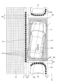
図7は、本実施形態の駐車支援装置10を搭載した車両1が、道路脇の駐車スペースPに縦列駐車を行う場面を示す平面図である。図8は、図7に示す車両1が障害物である縁石Cの手前で停止した状態を示す拡大図である。 Figure 7 is a plan view showing a scene in which a vehicle 1 equipped with the parking assistance device 10 of this embodiment is parallel parking in a parking space P on the side of a road. Figure 8 is an enlarged view showing the state in which the vehicle 1 shown in Figure 7 has stopped in front of a curb C, which is an obstacle.
前述の図5および図6に示す例では、駐車支援装置10の演算解析機能F12は、車両1を駐車するのに必要な空間と、道路脇、すなわち道路Rの歩道W側の部分における障害物が存在しない空間とを比較して駐車予定位置Lpを算出した。しかし、図7および図8に示す例において、駐車支援装置10の演算解析機能F12は、たとえば、外界センサ4の外界情報Ieに基づいて認識された駐車スペースPを画定する枠線Fの内側の領域に駐車予定位置Lpを設定することができる。 In the example shown in Figures 5 and 6, the calculation and analysis function F12 of the parking assistance device 10 calculated the planned parking position Lp by comparing the space required to park the vehicle 1 with the space on the side of the road, i.e., the sidewalk W side of the road R, where there are no obstacles. However, in the example shown in Figures 7 and 8, the calculation and analysis function F12 of the parking assistance device 10 can set the planned parking position Lp, for example, in the area inside the frame line F that defines the parking space P recognized based on the external environment information Ie of the external environment sensor 4.
図7および図8に示す例では、図5および図6に示す例と同様に、車両1が最初に後退を開始する制御開始位置Dpで、駐車支援装置10は、物体の位置Poである縁石Cの位置を、実際の縁石Cの位置よりも歩道W側の座標点列Scとして認識している。そのため、図4に示す処理P4において、駐車支援装置10の演算解析機能F12は、たとえば図7に示すように、車両1の駐車予定位置Lpを、適切な位置よりも縁石Cに近い位置に設定する場合がある。 In the example shown in Figures 7 and 8, similar to the example shown in Figures 5 and 6, at the control start position Dp where the vehicle 1 first starts to reverse, the parking assistance device 10 recognizes the position of the curb C, which is the object position Po, as a coordinate point sequence Sc that is closer to the sidewalk W than the actual position of the curb C. Therefore, in process P4 shown in Figure 4, the calculation analysis function F12 of the parking assistance device 10 may set the planned parking position Lp of the vehicle 1 to a position closer to the curb C than the appropriate position, for example, as shown in Figure 7.
この場合、図4に示す処理P10において、演算解析機能F12は、たとえば、車両1に接触する可能性がある障害物である縁石Cが認識された(YES)と判定し、処理P12において、車両制御装置7は、車両1を障害物の手前の停車位置で停車させる。次に、駐車支援装置10は、たとえば、演算解析機能F12により、駐車予定位置Lpの修正可能範囲Aを算出する処理P13を実行する。
In this case, in process P10 shown in FIG. 4, the calculation and analysis function F12 determines that, for example, a curb C that is an obstacle that may come into contact with the vehicle 1 has been recognized (YES), and in process P12, the
図8に示すように、修正可能範囲Aの歩道W側の境界Bwは、前述の図6に示す例と同様に設定することができる。また、修正可能範囲Aの道路R側の境界Brは、たとえば、次のように設定することができる。まず、車両1が走行経路Rpに沿って移動を開始した後に認識された道路標示である駐車スペースPの枠線Fの座標点列のうち、最も道路R側に位置する座標点p1,p2に基づいて、修正可能範囲Aの道路R側の境界Brを設定する。 As shown in FIG. 8, the boundary Bw on the sidewalk W side of the correctable range A can be set in the same way as the example shown in FIG. 6 described above. The boundary Br on the road R side of the correctable range A can be set, for example, as follows. First, the boundary Br on the road R side of the correctable range A is set based on the coordinate points p1 and p2 located closest to the road R side among the coordinate points of the frame line F of the parking space P, which is a road marking recognized after the vehicle 1 starts moving along the driving route Rp.
より具体的には、修正可能範囲Aの道路R側の境界Brは、たとえば、車両1の前後で駐車スペースPを画定する枠線Fの最も道路R側に位置する座標点p1,p2を結ぶ直線に設定することができる。また、車両1の前後の修正可能範囲Aの境界Bf,Bbは、たとえば、座標点p1,p2を通る車両1の幅方向の直線に設定することができる。以上のように、処理P13において、駐車支援装置10は、たとえば、演算解析機能F12により、修正可能範囲Aの車両1の前後、道路R側、および歩道W側の境界Bf,Bb,Br,Bwを設定し、修正可能範囲Aを画定することができる。 More specifically, the boundary Br on the road R side of the correctable range A can be set, for example, as a straight line connecting coordinate points p1 and p2 located closest to the road R side of the frame line F that defines the parking space P in front of and behind the vehicle 1. Furthermore, the boundaries Bf and Bb of the correctable range A in front of and behind the vehicle 1 can be set, for example, as a straight line in the width direction of the vehicle 1 that passes through coordinate points p1 and p2. As described above, in process P13, the parking assistance device 10 can, for example, use the calculation analysis function F12 to set the boundaries Bf, Bb, Br, and Bw of the correctable range A in front of and behind the vehicle 1, on the road R side, and on the sidewalk W side, to define the correctable range A.
その後、図8に示す例においても、図6に示す例と同様に、駐車支援装置10によって図4に示す処理P14を実行し、車両制御装置7と駐車支援装置10によって処理P8から処理P11までを繰り返すことで、車両1は、新たな走行経路Rp’に沿って走行し、修正駐車位置Lp’に到達する。すると、車両制御装置7は、処理P11において、車両1が目標位置に到達した(YES)と判定し、車両1を停車させる処理P15を実行し、図4に示す駐車支援の処理フローが終了する。
Then, in the example shown in FIG. 8, similar to the example shown in FIG. 6, the parking assistance device 10 executes process P14 shown in FIG. 4, and the
以上のように、本実施形態の駐車支援装置10は、車両1の駐車予定位置Lpと走行経路Rpとを算出する装置である。駐車支援装置10は、車両1に搭載された外界センサ4から車両1の周囲の外界情報Ieを取得し、外界情報Ieに基づいて物体を認識し、物体の位置に基づいて駐車予定位置Lpを算出し、車両1の制御開始位置から駐車予定位置Lpまでの走行経路Rpを算出する。さらに、駐車支援装置10は、車両1が走行経路Rpに沿って移動を開始した後に外界情報Ieに基づいて障害物が認識された場合に、その障害物の位置に基づいて駐車予定位置Lpの修正可能範囲Aを算出するとともに、その修正可能範囲Aに含まれる修正駐車位置Lp’までの走行経路Rp’を算出する。 As described above, the parking assistance device 10 of this embodiment is a device that calculates the planned parking position Lp and driving route Rp of the vehicle 1. The parking assistance device 10 acquires external environment information Ie around the vehicle 1 from the external environment sensor 4 mounted on the vehicle 1, recognizes an object based on the external environment information Ie, calculates the planned parking position Lp based on the position of the object, and calculates the driving route Rp from the control start position of the vehicle 1 to the planned parking position Lp. Furthermore, when an obstacle is recognized based on the external environment information Ie after the vehicle 1 starts moving along the driving route Rp, the parking assistance device 10 calculates the correctable range A of the planned parking position Lp based on the position of the obstacle, and calculates the driving route Rp' to the corrected parking position Lp' included in the correctable range A.
この構成により、駐車支援装置10は、車両1の縦列駐車の駐車支援を行って、縁石Cなどの歩道W側の障害物と車両1との間に適切な距離を確保しつつ、車両1が道路R側にはみ出すのを防止することができる。したがって、本実施形態の駐車支援装置10によれば、車両1をより適切な位置に駐車させることができ、車両1の運転者や搭乗者の安全性、利便性、および安心感を向上させることができる。 With this configuration, the parking assistance device 10 can assist in parallel parking of the vehicle 1, preventing the vehicle 1 from protruding onto the road R while maintaining an appropriate distance between the vehicle 1 and obstacles on the sidewalk W side, such as a curb C. Therefore, the parking assistance device 10 of this embodiment can park the vehicle 1 in a more appropriate position, improving the safety, convenience, and sense of security of the driver and passengers of the vehicle 1.
また、本実施形態の駐車支援装置10は、車両1の幅方向において障害物が駐車予定位置Lpに対して制御開始位置Dpの反対側に位置する場合に、障害物の種別を判定し、その種別に応じて幅方向における障害物と修正可能範囲Aとの間隔を設定する。この構成により、縁石Cのような高さの低い障害物の場合に、駐車後の車両1と障害物との間隔が必要以上に広くなるのを防止することができる。また、フェンスや壁のような高さが高い障害物の場合に、車両1の運転者や搭乗者の乗降に支障のない間隔を確保することができる。 In addition, when an obstacle is located on the opposite side of the control start position Dp from the intended parking position Lp in the width direction of the vehicle 1, the parking assistance device 10 of this embodiment determines the type of obstacle and sets the distance in the width direction between the obstacle and the correctable range A according to the type. With this configuration, in the case of a low obstacle such as a curb C, it is possible to prevent the distance between the vehicle 1 and the obstacle after parking from becoming wider than necessary. Also, in the case of a high obstacle such as a fence or wall, it is possible to ensure a distance that does not interfere with the driver and passengers getting on and off the vehicle 1.
また、本実施形態の駐車支援装置10は、車両1の前後方向において、たとえば駐車車両V1,V2などの障害物が駐車予定位置Lpの前方または後方に位置する場合に、車両1の幅方向において、障害物の端部の位置に基づいて、修正可能範囲Aの境界を設定する。この構成により、車両1の駐車後に、駐車車両V1,V2などの障害物に対して、車両1の幅方向において道路R側に極端にはみ出すことが防止される。これにより、車両1の運転者や搭乗者の安全を確保し、車両1の運転者や搭乗者が不自然さや危険を感じるのを防止できる。 In addition, the parking assistance device 10 of this embodiment sets the boundary of the correctable range A in the width direction of the vehicle 1 based on the position of the end of the obstacle when an obstacle such as parked vehicles V1, V2 is located in front of or behind the intended parking position Lp in the longitudinal direction of the vehicle 1. This configuration prevents the vehicle 1 from protruding too far toward the road R in the width direction of the vehicle 1 relative to the obstacle such as parked vehicles V1, V2 after the vehicle 1 is parked. This ensures the safety of the driver and passengers of the vehicle 1 and prevents the driver and passengers of the vehicle 1 from feeling unnatural or unsafe.
また、本実施形態の駐車支援装置10は、車両1の駐車が可能な位置を示す道路標示である枠線Fを外界情報Ieに基づいて認識し、道路標示の有無に応じて修正可能範囲Aを設定する。この構成により、駐車が可能な位置を示す道路標示である枠線Fの有無にかかわらず、車両1を適切な位置に駐車することが可能になる。 The parking assistance device 10 of this embodiment also recognizes frame lines F, which are road markings that indicate positions where the vehicle 1 can be parked, based on the external environment information Ie, and sets the correction range A depending on the presence or absence of road markings. This configuration makes it possible to park the vehicle 1 in an appropriate position regardless of the presence or absence of frame lines F, which are road markings that indicate positions where parking can be performed.
以上説明したように、本実施形態によれば、車両1をより適切な位置に駐車させることが可能な駐車支援装置10を提供することができる。 As described above, this embodiment provides a parking assistance device 10 that can park the vehicle 1 in a more appropriate position.
以上、図面を用いて本開示に係る駐車支援装置の実施形態を詳述してきたが、具体的な構成はこの実施形態に限定されるものではなく、本開示の要旨を逸脱しない範囲における設計変更等があっても、それらは本開示に含まれるものである。 Although an embodiment of the parking assistance device according to the present disclosure has been described in detail above using the drawings, the specific configuration is not limited to this embodiment, and even if there are design changes, etc., within the scope that does not deviate from the gist of this disclosure, they are included in this disclosure.
1 車両
4 外界センサ
10 駐車支援装置
A 修正可能範囲
Br 境界
C 縁石(物体、障害物)
Dp 制御開始位置
F 枠線(物体、道路標示)
Ie 外界情報
Lp 駐車予定位置
Lp’ 修正駐車位置
Rp 走行経路
Rp’ 走行経路
V1 駐車車両(物体、障害物)
V2 駐車車両(物体、障害物)
1 Vehicle 4 External sensor 10 Parking assistance device A Correctable range Br Boundary C Curb (object, obstacle)
Dp Control start position F Frame line (object, road marking)
Ie External environment information Lp Planned parking position Lp' Corrected parking position Rp Travel route Rp' Travel route V1 Parked vehicle (object, obstacle)
V2 Parked vehicles (objects, obstacles)
Claims (1)
前記車両に搭載された外界センサから前記車両の周囲の外界情報を取得し、
前記外界情報に基づいて物体を認識し、
前記物体の位置に基づいて前記駐車予定位置を算出し、
前記車両の制御開始位置から前記駐車予定位置までの前記走行経路を算出し、
前記車両が前記走行経路に沿って移動を開始した後に前記外界情報に基づいて、駐車車両、縁石、フェンス及び壁のいずれかが認識された場合に、前記車両を前記駐車車両、前記縁石、前記フェンス及び前記壁のいずれかの手前の停車位置で停車させ、前記駐車車両、前記縁石、前記フェンス及び前記壁のいずれかの位置に基づいて前記駐車予定位置の修正可能範囲を算出するとともに前記停車位置から前記修正可能範囲に含まれる修正駐車位置までの前記走行経路を算出し、
前記修正可能範囲の算出では、前記修正可能範囲の前記車両の前後、道路側、および歩道側の境界を設定し、
前記修正可能範囲の前記道路側の境界は、前記車両が前記走行経路に沿って移動を開始した後に認識された前記駐車車両の座標点列のうち、最も前記道路側に位置する座標点を抽出して、前記車両の幅方向において、抽出した最も前記道路側に位置する座標点と、該座標点から前記道路側への前記駐車予定位置の許容突出量に基づいて設定され、
前記修正可能範囲の前記歩道側の境界は、
前記車両が前記走行経路に沿って移動を開始した後に認識された前記縁石の座標点列のうち、最も前記道路側に位置する座標点を抽出して、前記車両の幅方向において、抽出した最も前記道路側に位置する前記縁石の座標点と、前記駐車予定位置との間の隙間の最小幅に基づいて設定され、
前記車両の幅方向において、前記縁石、前記フェンス及び前記壁のいずれかが前記駐車予定位置に対して前記歩道側に位置する場合に、パターンマッチングにより前記縁石、前記フェンス及び前記壁のいずれかであるかの種別を判定し、
前記縁石が前記歩道側に位置する場合における前記修正可能範囲の前記歩道側の境界と前記縁石との間の間隔が、前記フェンス及び前記壁のいずれかが前記歩道側に位置する場合における前記修正可能範囲の前記歩道側の境界と前記フェンス及び前記壁のいずれかとの間の間隔よりも小さくなるように設定され、
前記修正可能範囲の前記車両の前後の境界は、前記駐車予定位置に駐車した前記車両と、前記車両の前後の前記駐車車両の座標点列との間に、前記駐車予定位置に駐車した前記車両が、前記車両の前後の前記駐車車両の間から前記道路へ退出すること可能な間隔が確保されるように設定され、
前記停車位置から前記修正可能範囲に含まれる前記修正駐車位置までの前記走行経路を算出できない場合には、前記停車位置から前記制御開始位置までの前記走行経路を算出し、前記制御開始位置から前記修正駐車位置までの前記走行経路を算出する
ことを特徴とする駐車支援装置。 A parking assistance device that performs parallel parking assistance for a vehicle by calculating a planned parking position and a driving route of the vehicle,
acquiring external environment information around the vehicle from an external environment sensor mounted on the vehicle;
Recognizing an object based on the external environment information;
Calculating the intended parking position based on the position of the object;
Calculating the driving route from a control start position of the vehicle to the planned parking position;
when a parked vehicle, a curb, a fence, or a wall is recognized based on the external environment information after the vehicle has started moving along the travel route , the vehicle is stopped at a stopping position in front of the parked vehicle, the curb, the fence, or the wall, and a correctable range of the intended parking position is calculated based on the position of the parked vehicle, the curb, the fence, or the wall, and the travel route from the stopping position to a corrected parking position included in the correctable range is calculated;
In the calculation of the correction possible range, boundaries of the correction possible range are set in front of and behind the vehicle, on the road side, and on the sidewalk side;
the road side boundary of the correction possible range is set by extracting a coordinate point located closest to the road side from among a sequence of coordinate points of the parked vehicle recognized after the vehicle starts moving along the driving route, and based on the extracted coordinate point located closest to the road side in a width direction of the vehicle and an allowable protrusion amount of the intended parking position from the coordinate point toward the road side;
The sidewalk side boundary of the correctable range is
a coordinate point located closest to the road among a sequence of coordinate points of the curb recognized after the vehicle starts moving along the travel route is extracted, and the parking position is set based on a minimum width of a gap between the extracted coordinate point of the curb located closest to the road in a width direction of the vehicle and the intended parking position ;
When any one of the curb, the fence, and the wall is located on the sidewalk side with respect to the intended parking position in a width direction of the vehicle, determining the type of the curb, the fence, or the wall by pattern matching;
a distance between the sidewalk-side boundary of the correctable range and the curb when the curb is located on the sidewalk side is set to be smaller than a distance between the sidewalk-side boundary of the correctable range and either the fence or the wall when either the fence or the wall is located on the sidewalk side,
the boundaries in front and behind the vehicle of the correction possible range are set between the vehicle parked at the intended parking position and the coordinate point sequences of the parked vehicles in front and behind the vehicle so that a distance is secured between the vehicle parked at the intended parking position and the coordinate point sequences of the parked vehicles in front and behind the vehicle, allowing the vehicle parked at the intended parking position to exit to the road from between the parked vehicles in front and behind the vehicle ;
When the driving route from the stopping position to the corrected parking position included in the correction range cannot be calculated, the driving route from the stopping position to the control start position is calculated, and the driving route from the control start position to the corrected parking position is calculated.
A parking assistance device comprising:
Priority Applications (1)
| Application Number | Priority Date | Filing Date | Title |
|---|---|---|---|
| JP2020023853A JP7532043B2 (en) | 2020-02-14 | 2020-02-14 | Parking Assistance Device |
Applications Claiming Priority (1)
| Application Number | Priority Date | Filing Date | Title |
|---|---|---|---|
| JP2020023853A JP7532043B2 (en) | 2020-02-14 | 2020-02-14 | Parking Assistance Device |
Publications (2)
| Publication Number | Publication Date |
|---|---|
| JP2021128641A JP2021128641A (en) | 2021-09-02 |
| JP7532043B2 true JP7532043B2 (en) | 2024-08-13 |
Family
ID=77488772
Family Applications (1)
| Application Number | Title | Priority Date | Filing Date |
|---|---|---|---|
| JP2020023853A Active JP7532043B2 (en) | 2020-02-14 | 2020-02-14 | Parking Assistance Device |
Country Status (1)
| Country | Link |
|---|---|
| JP (1) | JP7532043B2 (en) |
Citations (3)
| Publication number | Priority date | Publication date | Assignee | Title |
|---|---|---|---|---|
| JP2008302711A (en) | 2007-06-05 | 2008-12-18 | Denso Corp | Start support device |
| JP2017033298A (en) | 2015-07-31 | 2017-02-09 | アイシン精機株式会社 | Parking support apparatus |
| JP2018036915A (en) | 2016-08-31 | 2018-03-08 | アイシン精機株式会社 | Parking support device |
-
2020
- 2020-02-14 JP JP2020023853A patent/JP7532043B2/en active Active
Patent Citations (3)
| Publication number | Priority date | Publication date | Assignee | Title |
|---|---|---|---|---|
| JP2008302711A (en) | 2007-06-05 | 2008-12-18 | Denso Corp | Start support device |
| JP2017033298A (en) | 2015-07-31 | 2017-02-09 | アイシン精機株式会社 | Parking support apparatus |
| JP2018036915A (en) | 2016-08-31 | 2018-03-08 | アイシン精機株式会社 | Parking support device |
Also Published As
| Publication number | Publication date |
|---|---|
| JP2021128641A (en) | 2021-09-02 |
Similar Documents
| Publication | Publication Date | Title |
|---|---|---|
| CN108216226B (en) | collision avoidance aid | |
| US10913496B2 (en) | Parking assistance device | |
| JP6015314B2 (en) | Device for calculating parking target position, method and program for calculating parking target position | |
| CN105683000B (en) | Automatic stopping control device and parking aid | |
| JP6474888B2 (en) | Method for driving a vehicle at least semi-autonomously, driver assistance system and vehicle | |
| US10077045B2 (en) | Parking assist system, method, and non-transitory computer readable medium storing program | |
| CN113942498B (en) | Collision avoidance aid | |
| JP7429589B2 (en) | Vehicle movement support system | |
| CN108216224B (en) | collision avoidance aid | |
| JP4946631B2 (en) | Start support device, display device | |
| WO2018220912A1 (en) | Periphery monitoring device | |
| JP6607826B2 (en) | Travel control device | |
| CN1819944A (en) | Driver assistance devices especially for parking the car | |
| CN113942499A (en) | Collision avoidance aid | |
| JP6960979B2 (en) | Parking support system | |
| JP6637474B2 (en) | Travel control device, travel control method, and vehicle | |
| CN112977423A (en) | Parking assist system | |
| CN107792177A (en) | Parking assistance system | |
| JP7213149B2 (en) | VEHICLE CONTROL DEVICE, VEHICLE, OPERATING METHOD AND PROGRAM OF VEHICLE CONTROL DEVICE | |
| CN115335885B (en) | Vehicle control devices, vehicle merging auxiliary devices and vehicles | |
| CN114670810B (en) | Parking aid | |
| US11735049B2 (en) | Park assist system | |
| JP7532043B2 (en) | Parking Assistance Device | |
| JP2022141997A (en) | Vehicle control device | |
| WO2023054521A1 (en) | Parking assist system |
Legal Events
| Date | Code | Title | Description |
|---|---|---|---|
| A621 | Written request for application examination |
Free format text: JAPANESE INTERMEDIATE CODE: A621 Effective date: 20221125 |
|
| A977 | Report on retrieval |
Free format text: JAPANESE INTERMEDIATE CODE: A971007 Effective date: 20230831 |
|
| A131 | Notification of reasons for refusal |
Free format text: JAPANESE INTERMEDIATE CODE: A131 Effective date: 20230912 |
|
| A521 | Request for written amendment filed |
Free format text: JAPANESE INTERMEDIATE CODE: A523 Effective date: 20231109 |
|
| A131 | Notification of reasons for refusal |
Free format text: JAPANESE INTERMEDIATE CODE: A131 Effective date: 20240206 |
|
| A521 | Request for written amendment filed |
Free format text: JAPANESE INTERMEDIATE CODE: A523 Effective date: 20240403 |
|
| TRDD | Decision of grant or rejection written | ||
| A01 | Written decision to grant a patent or to grant a registration (utility model) |
Free format text: JAPANESE INTERMEDIATE CODE: A01 Effective date: 20240702 |
|
| A61 | First payment of annual fees (during grant procedure) |
Free format text: JAPANESE INTERMEDIATE CODE: A61 Effective date: 20240731 |
|
| R150 | Certificate of patent or registration of utility model |
Ref document number: 7532043 Country of ref document: JP Free format text: JAPANESE INTERMEDIATE CODE: R150 |