JP7538111B2 - Solar power plant and installation method for solar power plant - Google Patents
Solar power plant and installation method for solar power plant Download PDFInfo
- Publication number
- JP7538111B2 JP7538111B2 JP2021507521A JP2021507521A JP7538111B2 JP 7538111 B2 JP7538111 B2 JP 7538111B2 JP 2021507521 A JP2021507521 A JP 2021507521A JP 2021507521 A JP2021507521 A JP 2021507521A JP 7538111 B2 JP7538111 B2 JP 7538111B2
- Authority
- JP
- Japan
- Prior art keywords
- module
- mat
- profiles
- power plant
- profile
- Prior art date
- Legal status (The legal status is an assumption and is not a legal conclusion. Google has not performed a legal analysis and makes no representation as to the accuracy of the status listed.)
- Active
Links
Images



Classifications
-
- H—ELECTRICITY
- H02—GENERATION; CONVERSION OR DISTRIBUTION OF ELECTRIC POWER
- H02S—GENERATION OF ELECTRIC POWER BY CONVERSION OF INFRARED RADIATION, VISIBLE LIGHT OR ULTRAVIOLET LIGHT, e.g. USING PHOTOVOLTAIC [PV] MODULES
- H02S20/00—Supporting structures for PV modules
-
- H—ELECTRICITY
- H02—GENERATION; CONVERSION OR DISTRIBUTION OF ELECTRIC POWER
- H02S—GENERATION OF ELECTRIC POWER BY CONVERSION OF INFRARED RADIATION, VISIBLE LIGHT OR ULTRAVIOLET LIGHT, e.g. USING PHOTOVOLTAIC [PV] MODULES
- H02S10/00—PV power plants; Combinations of PV energy systems with other systems for the generation of electric power
- H02S10/40—Mobile PV generator systems
-
- B—PERFORMING OPERATIONS; TRANSPORTING
- B63—SHIPS OR OTHER WATERBORNE VESSELS; RELATED EQUIPMENT
- B63B—SHIPS OR OTHER WATERBORNE VESSELS; EQUIPMENT FOR SHIPPING
- B63B35/00—Vessels or similar floating structures specially adapted for specific purposes and not otherwise provided for
- B63B35/44—Floating buildings, stores, drilling platforms, or workshops, e.g. carrying water-oil separating devices
-
- H—ELECTRICITY
- H02—GENERATION; CONVERSION OR DISTRIBUTION OF ELECTRIC POWER
- H02S—GENERATION OF ELECTRIC POWER BY CONVERSION OF INFRARED RADIATION, VISIBLE LIGHT OR ULTRAVIOLET LIGHT, e.g. USING PHOTOVOLTAIC [PV] MODULES
- H02S20/00—Supporting structures for PV modules
- H02S20/20—Supporting structures directly fixed to an immovable object
-
- H—ELECTRICITY
- H02—GENERATION; CONVERSION OR DISTRIBUTION OF ELECTRIC POWER
- H02S—GENERATION OF ELECTRIC POWER BY CONVERSION OF INFRARED RADIATION, VISIBLE LIGHT OR ULTRAVIOLET LIGHT, e.g. USING PHOTOVOLTAIC [PV] MODULES
- H02S30/00—Structural details of PV modules other than those related to light conversion
-
- H—ELECTRICITY
- H02—GENERATION; CONVERSION OR DISTRIBUTION OF ELECTRIC POWER
- H02S—GENERATION OF ELECTRIC POWER BY CONVERSION OF INFRARED RADIATION, VISIBLE LIGHT OR ULTRAVIOLET LIGHT, e.g. USING PHOTOVOLTAIC [PV] MODULES
- H02S30/00—Structural details of PV modules other than those related to light conversion
- H02S30/10—Frame structures
-
- H—ELECTRICITY
- H02—GENERATION; CONVERSION OR DISTRIBUTION OF ELECTRIC POWER
- H02S—GENERATION OF ELECTRIC POWER BY CONVERSION OF INFRARED RADIATION, VISIBLE LIGHT OR ULTRAVIOLET LIGHT, e.g. USING PHOTOVOLTAIC [PV] MODULES
- H02S40/00—Components or accessories in combination with PV modules, not provided for in groups H02S10/00 - H02S30/00
- H02S40/30—Electrical components
- H02S40/34—Electrical components comprising specially adapted electrical connection means to be structurally associated with the PV module, e.g. junction boxes
-
- H—ELECTRICITY
- H10—SEMICONDUCTOR DEVICES; ELECTRIC SOLID-STATE DEVICES NOT OTHERWISE PROVIDED FOR
- H10F—INORGANIC SEMICONDUCTOR DEVICES SENSITIVE TO INFRARED RADIATION, LIGHT, ELECTROMAGNETIC RADIATION OF SHORTER WAVELENGTH OR CORPUSCULAR RADIATION
- H10F19/00—Integrated devices, or assemblies of multiple devices, comprising at least one photovoltaic cell covered by group H10F10/00, e.g. photovoltaic modules
- H10F19/80—Encapsulations or containers for integrated devices, or assemblies of multiple devices, having photovoltaic cells
- H10F19/807—Double-glass encapsulation, e.g. photovoltaic cells arranged between front and rear glass sheets
-
- B—PERFORMING OPERATIONS; TRANSPORTING
- B63—SHIPS OR OTHER WATERBORNE VESSELS; RELATED EQUIPMENT
- B63B—SHIPS OR OTHER WATERBORNE VESSELS; EQUIPMENT FOR SHIPPING
- B63B35/00—Vessels or similar floating structures specially adapted for specific purposes and not otherwise provided for
- B63B35/44—Floating buildings, stores, drilling platforms, or workshops, e.g. carrying water-oil separating devices
- B63B2035/4433—Floating structures carrying electric power plants
- B63B2035/4453—Floating structures carrying electric power plants for converting solar energy into electric energy
-
- Y—GENERAL TAGGING OF NEW TECHNOLOGICAL DEVELOPMENTS; GENERAL TAGGING OF CROSS-SECTIONAL TECHNOLOGIES SPANNING OVER SEVERAL SECTIONS OF THE IPC; TECHNICAL SUBJECTS COVERED BY FORMER USPC CROSS-REFERENCE ART COLLECTIONS [XRACs] AND DIGESTS
- Y02—TECHNOLOGIES OR APPLICATIONS FOR MITIGATION OR ADAPTATION AGAINST CLIMATE CHANGE
- Y02E—REDUCTION OF GREENHOUSE GAS [GHG] EMISSIONS, RELATED TO ENERGY GENERATION, TRANSMISSION OR DISTRIBUTION
- Y02E10/00—Energy generation through renewable energy sources
- Y02E10/50—Photovoltaic [PV] energy
-
- Y—GENERAL TAGGING OF NEW TECHNOLOGICAL DEVELOPMENTS; GENERAL TAGGING OF CROSS-SECTIONAL TECHNOLOGIES SPANNING OVER SEVERAL SECTIONS OF THE IPC; TECHNICAL SUBJECTS COVERED BY FORMER USPC CROSS-REFERENCE ART COLLECTIONS [XRACs] AND DIGESTS
- Y02—TECHNOLOGIES OR APPLICATIONS FOR MITIGATION OR ADAPTATION AGAINST CLIMATE CHANGE
- Y02E—REDUCTION OF GREENHOUSE GAS [GHG] EMISSIONS, RELATED TO ENERGY GENERATION, TRANSMISSION OR DISTRIBUTION
- Y02E10/00—Energy generation through renewable energy sources
- Y02E10/70—Wind energy
- Y02E10/727—Offshore wind turbines
Landscapes
- Engineering & Computer Science (AREA)
- Architecture (AREA)
- Civil Engineering (AREA)
- Structural Engineering (AREA)
- Chemical & Material Sciences (AREA)
- Combustion & Propulsion (AREA)
- Mechanical Engineering (AREA)
- Ocean & Marine Engineering (AREA)
- Photovoltaic Devices (AREA)
- Hybrid Cells (AREA)
- Roof Covering Using Slabs Or Stiff Sheets (AREA)
Description
本発明は、再生可能エネルギー生成に関し、より詳しくは、フレキシブルウェブ又はメンブレン上に取り付けられた複数の光電池モジュールを含む水上ソーラー発電プラントに関する装置と方法に関する。 The present invention relates to renewable energy generation, and more particularly to an apparatus and method for a floating solar power plant that includes a plurality of photovoltaic modules mounted on a flexible web or membrane.
背景
水上光電池(PV)太陽光発電システムは知られているが、現時点では広く普及していない。このようなシステムは典型的に、平水に、すなわち湖水、水力発電所のダム、貯水池、河川等に展開される。水上太陽光発電システムに係わる問題の幾つかとしては、波や流れからの負荷にさらされること、プラント(又はその構成要素)の展開が困難であり、多大な労力を要すること、並びにシステムの保守及び(例えば、プラント表面に堆積する塩又は固体粒子の)クリーニングのためのアクセスに伴う問題が含まれる。現在利用可能な水上太陽光発電システムはまた、それらの比較的高いコストによっても限定される。
2. Background Floating photovoltaic (PV) solar power systems are known but not currently in widespread use. Such systems are typically deployed on flat water, i.e., lakes, hydroelectric dams, reservoirs, rivers, etc. Some of the problems associated with floating solar power systems include exposure to loads from waves and currents, difficult and labor-intensive deployment of the plant (or its components), and problems with access for system maintenance and cleaning (e.g., of salt or solid particles that accumulate on the plant surface). Currently available floating solar power systems are also limited by their relatively high cost.
背景を理解する上で有益であり得る先行技術の例としては、大規模海洋移動式太陽光発電システムが記載されている米国特許出願公開第2012/0242275 A1号、ソーラーパネル用支持装置が記載されている米国特許出願公開第2015/0162866 A1号、太陽光発電パネル支持用装置が記載されている米国特許出願公開第2014/0224165 A1号、浮動機器上に配置される太陽電池が記載されている韓国特許第1011013316 B号及び韓国特許第101612832 B号、並びに使用時に水体表面上に浮上するフレキシブルメンブレン上に複数の硬質PVモジュールを含む太陽光発電プラントが開示されている国際公開第2017/209625号が含まれる。 Examples of prior art that may be useful in understanding the background include U.S. Patent Application Publication No. 2012/0242275 A1, which describes a large-scale marine mobile solar power generation system, U.S. Patent Application Publication No. 2015/0162866 A1, which describes a support device for solar panels, U.S. Patent Application Publication No. 2014/0224165 A1, which describes a device for supporting solar power panels, Korean Patent Nos. 1011013316 B and 101612832 B, which describe solar cells disposed on floating equipment, and International Publication No. WO 2017/209625, which discloses a solar power generation plant including a plurality of rigid PV modules on a flexible membrane that floats above the surface of a body of water in use.
現在、水上PV発電プラントには技術的、経済的両方の問題がある。その結果、様々な用途及び目的のためのこのような再生可能発電のための改良されたシステムと方法が求められている。本発明は、水上太陽光発電プラントに関する改良された装置と方法を提供し、有利となる、及び/又は既知のシステム及び技術に伴う現在の問題若しくは欠点を修復することを目指す。 Currently, floating PV power plants have both technical and economic problems. As a result, there is a need for improved systems and methods for such renewable power generation for a variety of applications and purposes. The present invention seeks to provide improved apparatus and methods for floating solar power plants that are advantageous and/or remedy current problems or shortcomings with known systems and techniques.
概要
第一の態様によれば、本願は、その上に固定された複数の光電池(PV)モジュールを有する柔軟マットを含み、各モジュールは、上板と下板との間に挟まれた光電池セルの層を含み、下板がマットの上面上に、又はそれに直接隣接して配置されるようにマットに固定される、太陽光発電プラントを提供する。
SUMMARY According to a first aspect, the present application provides a solar power plant including a flexible mat having a plurality of photovoltaic (PV) modules secured thereto, each module including a layer of photovoltaic cells sandwiched between an upper plate and a lower plate, the lower plate being secured to the mat such that it is disposed on or directly adjacent to an upper surface of the mat.
下板は、ガラス板であってよい。 The bottom plate may be a glass plate.
下板の厚さは0.5mm~4mmの間、1mm~3mmの間、又は約2.5mmであってよい。 The thickness of the bottom plate may be between 0.5mm and 4mm, between 1mm and 3mm, or about 2.5mm.
上板は透明又は半透明であってよい。上板は、ガラス板又はポリマ板であってよい。 The top plate may be transparent or translucent. The top plate may be a glass plate or a polymer plate.
上板の厚さは0.5mm~4mmの間、1mm~3mmの間、又は約2.5mmであってよい。 The thickness of the top plate may be between 0.5mm and 4mm, between 1mm and 3mm, or about 2.5mm.
上及び下板は同じ厚さを有していてよい。 The upper and lower plates may have the same thickness.
マットの厚さは0.3mm~5mmの間、0.5mm~1.5mmの間、又は約1mmであってよい。 The thickness of the mat may be between 0.3mm and 5mm, between 0.5mm and 1.5mm, or about 1mm.
PVモジュールの少なくとも1つは、PVモジュール1の相互に反対側にある概して平行な2つの縁辺に固定される2つの長いモジュール異形材と、マットに取り付けられる、対応する2つの長いマット異形材とを含む取付けアセンブリによってマットに固定されてよい。
At least one of the PV modules may be secured to the mat by a mounting assembly including two long module profiles secured to two generally parallel, opposing edges of the
異形材は、PVモジュールがマットに、PVモジュール上の異形材をマット上の対応する異形材と接触させ、これらの異形材を、PVモジュールのその縁辺に概して垂直な力が加えられることによる2つの異形材の分離が実質的に防止される所望の最終位置にそれらが到達するまで、モジュール異形材が固定されるPVモジュールの縁辺に概して平行な方向に相互に関してスライドさせることによって固定されるように構成されてよい。 The profiles may be configured such that the PV module is secured to the mat by contacting the profiles on the PV module with corresponding profiles on the mat and sliding the profiles relative to each other in a direction generally parallel to the edge of the PV module to which the module profile is secured until they reach a desired final position in which separation of the two profiles due to application of a generally perpendicular force to that edge of the PV module is substantially prevented.
ファスナが提供されてよく、ファスナは、係合すると、2つの異形材がそれ以上、PVモジュールの縁辺に概して平行に相対移動するのを防止する。 A fastener may be provided which, when engaged, prevents further relative movement of the two profiles generally parallel to the edges of the PV module.
モジュール異形材は、PVモジュールの縁辺に接着剤で結合されてよい。 The module profile may be adhesively bonded to the edges of the PV module.
マット異形材は、マットに溶接又は縫い止めされてよい。 The mat profile may be welded or sewn to the mat.
モジュール異形材は、それが取り付けられるPVモジュールの縁辺に概して平行に延びる長い保持部を含んでいてもよい。 The module profile may include an elongated retaining portion that extends generally parallel to the edge of the PV module to which it is attached.
保持部は、基部により接続される概して平行な2つの脚を有する長いフレーム部によりPVモジュールに接続されてよい。 The holder may be connected to the PV module by a long frame portion having two generally parallel legs connected by a base.
脚は、接着剤によって下及び上ガラス板に固定されてよい。 The legs may be secured to the lower and upper glass panes by adhesive.
フレーム部は、保持部と一体化されてよい。 The frame portion may be integrated with the holding portion.
モジュール異形材は、PVモジュールの縁辺全体に沿って延びていてよい。 The module profile may extend along the entire edge of the PV module.
マット異形材は長い保持部を含んでいてよく、これはモジュール異形材の保持部と嵌合するように構成され、ウェブを使ってマットに固定される。ウェブにより、マットと保持部との間の分離が、保持部の実質的に全長に沿って概して一定であることが確実となってもよい。 The mat profile may include an elongated retaining portion configured to mate with the retaining portion of the module profile and secured to the mat using a web. The web may ensure that the separation between the mat and the retaining portion is generally constant along substantially the entire length of the retaining portion.
保持部の一方は、他方の保持部の対応する雌部に挿入される雄部を有していてよい。 One of the retaining parts may have a male part that is inserted into a corresponding female part of the other retaining part.
雄部は長い管又はロッドを含んでいてよく、他方で雌部はその長さ方向軸に平行に延びる割れ目を有する長い管を含む。 The male portion may comprise a long tube or rod, while the female portion comprises a long tube having a slit running parallel to its longitudinal axis.
マットは浮動要素に固定されてよい。 The mat may be fixed to the floating element.
浮動要素は、マットを取り囲む無限の長い浮動要素であってよい。 The floating element may be an infinitely long floating element that surrounds the mat.
第二の態様によれば、本願は、フレキシブルマットを水体上に、マットが水体表面上又はその付近に浮くように展開するステップを含む、第一の態様による水上光電池発電プラントの据付方法を提供する。 According to a second aspect, the present application provides a method for installing a floating photovoltaic power plant according to the first aspect, comprising the step of deploying a flexible mat onto the body of water such that the mat floats on or near the surface of the body of water.
マットは、下ガラス板が水体と直接接触するように展開されてよい。 The mat may be deployed so that the lower glass sheet is in direct contact with the body of water.
太陽光発電プラントを展開するステップは、船舶から行われてよい。 The step of deploying the solar power plant may be performed from a marine vessel.
方法は、折り畳み、積み重ねた太陽光発電プラントを船舶に載せて輸送することをさらに含んでいてもよい。 The method may further include transporting the folded and stacked solar power plant on a vessel.
太陽光発電プラントを展開するステップは、陸上位置から行われてよい。 The step of deploying the solar power plant may be performed from a land-based location.
第三の態様によれば、本願は、柔軟マットであって、その上に光電池(PV)モジュールであって、PVモジュールの縁辺に固定される少なくとも1つの長いモジュール異形材と、マットに取り付けられる対応する長いマット異形材とを含む取付けアセンブリによって固定された光電池(PV)モジュールを有する柔軟マットを含む太陽光発電プラントを提供する。 According to a third aspect, the present application provides a photovoltaic power plant comprising a flexible mat having a photovoltaic (PV) module thereon secured by a mounting assembly including at least one elongated module profile secured to an edge of the PV module and a corresponding elongated mat profile attached to the mat.
これらの異形材は、PVモジュールがマットに、モジュール異形材を対応するマット異形材と接触させ、両方の異形材を、PVモジュールの縁辺に概して垂直な力が加えられることによる2つの異形材の分離が実質的に防止される所望の最終位置にそれらが到達するまで、そのモジュール異形材が固定されるPVモジュールの縁辺に概して平行な方向に相互に関してスライドさせることによって固定されるように構成されてよい。 These profiles may be configured to be secured to the PV module by contacting the module profile with the corresponding mat profile and sliding both profiles relative to each other in a direction generally parallel to the edge of the PV module to which the module profile is secured until they reach a desired final position in which separation of the two profiles due to application of a force generally perpendicular to the edge of the PV module is substantially prevented.
PVモジュールは、第一の態様による太陽光発電プラントにおけるPVモジュールの何れの特徴又は特徴の組合せを有していてもよい。 The PV module may have any feature or combination of features of a PV module in a solar power plant according to the first aspect.
PVモジュールには、PVモジュールの相互に反対側にある概して平行な2つの縁辺に固定される2つのモジュール異形材と、対応する概して平行な2つのマット異形材が提供されてよい。 The PV module may be provided with two module profiles secured to two generally parallel opposite edges of the PV module, and two corresponding generally parallel mat profiles.
ファスナが提供されてよく、ファスナは、係合すると、2つの異形材がPVモジュールの縁辺に概して平行にそれ以上相対移動しないようにする。 A fastener may be provided which, when engaged, prevents further relative movement of the two profiles generally parallel to the edge of the PV module.
モジュール異形材は、PVモジュールの縁辺に接着剤で結合されてよい。 The module profile may be adhesively bonded to the edges of the PV module.
マット異形材は、マットに溶接又は縫い止めされてよい。 The mat profile may be welded or sewn to the mat.
モジュール異形材は、それが取り付けられるPVモジュール1の縁辺に概して平行に延びる長い保持部を含んでいてもよい。
The module profile may include an elongated retaining portion that extends generally parallel to the edge of the
保持部は、基部により接続される概して平行な2つの脚を有する長いフレーム部によってPVモジュールに接続されてよい。 The holder may be connected to the PV module by a long frame portion having two generally parallel legs connected by a base.
PVモジュールは、上板と下板との間に挟まれた光電池セルの層を含んでいてもよい。 The PV module may include a layer of photovoltaic cells sandwiched between a top plate and a bottom plate.
脚は、接着剤によって下板及び上板に固定されてよい。 The legs may be secured to the bottom and top plates by adhesive.
フレーム部は保持部と一体化されてよい。 The frame portion may be integrated with the holding portion.
モジュール異形材は、PVモジュールの縁辺全体に沿って延びてよい。 The module profile may extend along the entire edge of the PV module.
マット異形材は長い保持部を含んでいてよく、これは、モジュール異形材の保持部と嵌合するように構成され、ウェブを使ってマットに固定される。ウェブにより、マットと保持部との間の分離が保持部の実質的に全長に沿って概して一定であることが確実となってもよい。 The mat profile may include an elongated retaining portion configured to mate with the retaining portion of the module profile and secured to the mat using a web. The web may ensure that the separation between the mat and the retaining portion is generally constant along substantially the entire length of the retaining portion.
保持部の一方は、他方の保持部の対応する雌部に挿入される雄部を有していてよい。 One of the retaining parts may have a male part that is inserted into a corresponding female part of the other retaining part.
雄部は長い管又はロッドを含んでいてよく、他方で雌部はその長さ方向軸に平行に延びる割れ目を有する長い管を含む。 The male portion may comprise a long tube or rod, while the female portion comprises a long tube having a slit running parallel to its longitudinal axis.
マットは、浮動要素に固定されてよい。 The mat may be fixed to the floating element.
浮動要素は、マットを取り囲む無限の長い浮動要素であってよい。 The floating element may be an infinitely long floating element that surrounds the mat.
第四の態様によれば、本願は、第三の態様による水上光電池光発電プラントの据付方法を提供し、これは、PVモジュールをマットに、モジュール異形材を対応するマット異形材と接触させ、これらの異形材を、PVモジュールの縁辺に概して垂直な力が加えられることによる2つの異形材の分離が実質的に防止される所望の最終位置にそれらが到達するまで、モジュール異形材が固定されるPVモジュールの縁辺に概して平行な方向に相互に関してスライドさせることによって固定するステップを含む。 According to a fourth aspect, the present application provides a method of installation of a floating photovoltaic photovoltaic power plant according to the third aspect, comprising the steps of fixing the PV module to the mat and the module profiles to corresponding mat profiles by contacting the profiles with each other in a direction generally parallel to the edge of the PV module to which the module profiles are fixed, until they reach a desired final position in which separation of the two profiles due to application of a generally perpendicular force to the edge of the PV module is substantially prevented.
方法は、この方法ステップを実行した後に、2つの異形材がPVモジュールの縁辺に概して平行にそれ以上相対移動しないようにするためにファスナを動作させることを含んでいてもよい。 The method may include, after performing this method step, operating the fastener to prevent further relative movement of the two profiles generally parallel to the edge of the PV module.
モジュール異形材又はマット異形材の一方は、雄部である保持部を有し、他方は雌部である保持部を有していてよく、方法は、雌部をモジュール異形材が固定されるPVモジュールの縁辺に概して平行に雄部に関してスライドさせる前に、一方の異形材の雄部を、対応する各異形材の雌部の端に、雄部が少なくとも実質的に雌部により取り囲まれるまで挿入することを含む。 One of the module profiles or mat profiles may have a retaining portion that is a male portion and the other has a retaining portion that is a female portion, and the method includes inserting the male portion of one profile into the end of the female portion of each corresponding profile until the male portion is at least substantially surrounded by the female portion before sliding the female portion relative to the male portion generally parallel to an edge of the PV module to which the module profile is secured.
PVモジュールには、PVモジュールの相互に反対側にある概して平行な縁辺に固定される2つのモジュール異形材が設けられてよく、マットには、対応する、概して平行な2つのマット異形材が設けられていてよく、方法は、PVモジュールをマットに、同時に、一度に、又は逐次的に、両方のモジュール異形材をそれらの対応するマット異形材と接触させ、これらの異形材を、PVモジュールの縁辺に概して垂直な力が加えられることによる2つの異形材の分離が実質的に防止される所望の最終位置にそれらが到達するまで、モジュール異形材が固定されるPVモジュールの縁辺に概して平行な方向に相互に関してスライドさせることによって固定することを含んでいてもよい。 The PV module may be provided with two module profiles secured to generally parallel opposite edges of the PV module, and the mat may be provided with two corresponding generally parallel mat profiles, and the method may include securing the PV module to the mat simultaneously, one at a time, or sequentially by contacting both module profiles with their corresponding mat profiles and sliding the profiles relative to each other in a direction generally parallel to the edges of the PV module to which the module profiles are secured, until they reach a desired final position in which separation of the two profiles due to application of a generally perpendicular force to the edges of the PV module is substantially prevented.
方法は、PVモジュールをマットに固定するステップを実行する前に、マットを水体上に展開するステップをさらに含んでいてもよい。 The method may further include the step of unfolding the mat over the body of water prior to performing the step of securing the PV module to the mat.
方法は、PVモジュールがマットに固定された後に、マットを水体上に展開するステップを含んでいてもよい。 The method may include deploying the mat over the body of water after the PV modules are secured to the mat.
PVモジュールは、上ガラス板と下ガラス板との間に挟まれた光電池セルの層を含んでいてよく、方法は、発電プラントを、下ガラス板が水体と直接接触するように展開することをさらに含んでいてもよい。 The PV module may include a layer of photovoltaic cells sandwiched between an upper glass sheet and a lower glass sheet, and the method may further include deploying the power plant such that the lower glass sheet is in direct contact with the body of water.
太陽光発電プラントを展開するステップは、船舶から実行されてよい。 The step of deploying the solar power plant may be performed from a marine vessel.
方法は、折り畳み、積み重ねた太陽光発電プラントを船舶上で輸送することをさらに含んでいてもよい。 The method may further include transporting the folded and stacked solar power plant on a vessel.
太陽光発電プラントを展開するステップは、陸上位置から実行されてよい。 The step of deploying the solar power plant may be performed from a land-based location.
態様の何れにおいても、各モジュールは、上板が硬質の板である、下板が硬質の板である、又は上及び下板の両方が硬質の板であることによって実質的に硬質であってよい。モジュールは、有利には、折れるか又は曲がるほどしなやかでなくてよい。 In any of the embodiments, each module may be substantially rigid by having the upper plate be a rigid plate, the lower plate be a rigid plate, or both the upper and lower plates be rigid plates. The modules may advantageously not be so flexible that they will break or bend.
態様の何れにおいても、モジュールは、相互に接続されず、マットにのみ固定される別々のモジュールであってよい。各モジュールは、他のモジュールから離間されていてよい。 In any of the embodiments, the modules may be separate modules that are not connected to each other and are only secured to the mat. Each module may be spaced apart from the other modules.
態様の何れにおいても、モジュールは、モジュールの行と列のx-yパターンに配置されてよく、各行及び各列は複数の個別のモジュールを含む。 In any of the embodiments, the modules may be arranged in an x-y pattern of rows and columns of modules, with each row and each column containing multiple individual modules.
態様の何れにおいても、各モジュールは、配電のための1つ又は複数の接続箱を含んでいてもよい。接続箱は、それぞれのモジュールの上面上、モジュールの側面上、又は長いモジュール異形材上に位置付けられてよい。 In any of the aspects, each module may include one or more junction boxes for power distribution. The junction boxes may be located on the top surface of each module, on the side of the module, or on the elongated module profile.
図面の簡単な説明
以下に、例示的な実施形態を下記のような添付の図面に関して説明する。
BRIEF DESCRIPTION OF THE DRAWINGS Exemplary embodiments are described below with reference to the accompanying drawings as follows:
詳細な説明
石油ガス生産プラットフォーム、ボーリング、又は処理施設等の多くの固定又は洋上浮体式ユニットでは、稼働に膨大なエネルギーが必要となる。需要の多いその他の施設としては、大規模養殖場又は、送電網から離れた場所にある有人島が含まれる。これらの現場のエネルギー需要に対しては、一般にディーゼル又はガスタービン発電機を介して供給される。化石燃料源からの高いエネルギー消費及びその後の二酸化炭素放出により、この活動は環境問題専門家と政治家の間の活発な議論の的となっている。それに加えて、エネルギーコストはこのような施設の事業者及び所有者による重要な検討事項である。
DETAILED DESCRIPTION Many fixed or offshore floating units, such as oil and gas production platforms, drilling, or processing facilities, require significant amounts of energy to operate. Other facilities with high demands include large-scale aquaculture farms or inhabited islands located far from the grid. The energy needs of these sites are typically supplied via diesel or gas turbine generators. The high energy consumption from fossil fuel sources and the subsequent carbon dioxide emissions make this activity a hot topic of debate among environmentalists and politicians. Additionally, energy costs are a major consideration by operators and owners of such facilities.
本明細書に記載の実施形態によれば、通常の陸上送電網とのケーブルを通じた接続に適した、又は独立したオフグリッド発電に適した水上再生可能発電施設が提供される。実施形態は、沖合若しくは沿岸での洋上でも陸水上でも利用されてよく、例えば化石燃料に基づく発電機又は発電プラントに代わるものとして設計でき、それによって発電のカーボンフットプリントを削減できる。例えば、多くのメガシティを含む多くの人口密集地は沿岸部にある。このような地域では、風力及びソーラー等の従来の再生可能発電に利用可能な面積又は使用できる屋根が非常に限定されている。本明細書に記載の実施形態によれば、このような地域における再生可能発電に対する重要な貢献を、低コスト且つ高い動作信頼度で行うことができる。 According to the embodiments described herein, floating renewable power generation facilities are provided that are suitable for connection through a cable to a normal land grid or for independent off-grid generation. The embodiments may be used on ocean or inland waters, offshore or onshore, and can be designed, for example, as an alternative to fossil fuel-based generators or power plants, thereby reducing the carbon footprint of power generation. For example, many densely populated areas, including many megacities, are located on the coast. In such areas, the available area or available rooftops for traditional renewable power generation, such as wind and solar, are very limited. According to the embodiments described herein, a significant contribution to renewable power generation in such areas can be made at low cost and with high operational reliability.
このシステムの実施形態は様々な用途に適しており、例えば春、夏、秋の日中のエネルギー需要の大部分に置き換わり、又はそれを賄うように設計できる。例えば、PVは、ハイブリッド発電システムにおいてうまく機能し、このシステムでは、雲及び太陽の位置に応じた太陽エネルギーシステムからの出力変動に伴って発生する典型的な不規則性をフレックス燃料ベースの発電機によって容易に均すことができる。代替的に、エネルギー貯蔵のためにバッテリも使用されてよい。 Embodiments of this system are suitable for a variety of applications and can be designed to replace or cover a large portion of the daytime energy demands, for example, during spring, summer, and fall. For example, PV works well in a hybrid power generation system where flex-fuel based generators can easily smooth out the typical irregularities that occur with the output fluctuations from a solar energy system depending on clouds and the position of the sun. Alternatively, batteries may also be used for energy storage.
本発明は、以下においてマット2と呼ぶフレキシブルメンブレン又はウェブ上に取り付けられて、PVアレイを形成する複数のPVモジュール1を含む太陽光発電プラントを含む。PVアレイは浮揚性を有し、したがって海等の水体表面に浮いて、洋上太陽光発電プラントを形成することができる。これを実現するために、マット2は少なくとも部分的に浮力材で製作されてよく、及び/又はPVアレイはマット2に固定されるか、又はそこに組み込まれる浮動要素をさらに含んでいてもよい。この浮揚性を実現した様々方法は国際公開第2017/209625号に記載されている。
The invention comprises a photovoltaic power plant comprising a number of
基材マット2は十分にフレキシブルであり、基本的に海波の動きに追従し、一般に、いわゆる流力弾性挙動を見せる。裁断波や波しぶきは、大きい面積を覆ってよいマット2の存在によって有効に防止される。複数のマット2は相互に接続されてもよい。
The
マット2は、有孔であってもそうでなくても、凹部、一方向弁、ポンプ又は、マットの最上面に溜まる水(雨水等)を排出できるようなその他の装置を有していてもよく、いなくてもよい。マット2は、代替的に網で製作されてもよく、すなわち、比較的大きい開口を有していてもよい。希望に応じて、マット2の浮揚性は、マット2の一部又は実質的に全体の上に薄い水の膜が保持されるように設計できる。これは、マット2自体及び/又はPVモジュール1の冷却に有利であり得る。
The
好ましい実施形態において、マット2の厚さは0.3mm~5mmの間、より好ましくは0.5mm~1.5mmの間、最も好ましくは約1mmである。これらの数値の典型的誤差は+/-0.2mmであってよい。
In a preferred embodiment, the thickness of the
マット2は、大きい区画で製造可能な、例えばポリエチレン、ポリプロピレン、ポリウレタン、EVA、合成ゴム、又はコポリマ製のシート、網、織物、フィルム、又は板で構成できる。代替的に、布は多層にされ、及び又は気体、塩分濃度の低い水、浮揚性固体、オイル、ゼリー、発泡材、若しくはその他の構成要素を含むポケット又は長いトンネル状部分により部分的に膨張されてもよい。1つの好ましい実施形態において、マット2はポリマコーティングテキスタイルメンブレンである。複数のポリマ、例えばマット2の各面で異なるポリマ及び/又はポリマコーティングを構成する異なるポリマの層が使用されてもよい。
The
前述のように、PVアレイは、PVモジュール1の裏面が部分的に水中に沈んでいて熱を水に伝えられる状態で浮くのに十分な浮揚性を有するように設計できる。PVモジュール1は、それら自体が浮揚性を有していてもいなくてもよい。モジュールストリング2、すなわちアレイを形成する複数のストリングは、錨5、鎖によって、及び例えばポリエステル又はナイロン製の軽量ロープ4と組み合わせて海底に係留される。代替的な係留手段も可能であり、例えばモジュールストリング2は、例えば沿岸部又はダムでの使用においては、陸地に固定できる。図1に示される実施形態において、PV施設が海流及び/又は波漂流力によって引きずられないようにするために、ブイ3も取り付けられてよい。錨5及びブイ3の形状のほか、数と大きさは、横方向の漂流力を最小化するように設計できる。適切な浮揚力と錨の固定位置はまた、マットの周辺を取り囲む1つ又は複数の無限管状要素によっても提供できる。ブイ3には、船乗りに対して発電プラントの位置を表示するための適切なランタンも備えられてよい。
As mentioned above, the PV array can be designed to be buoyant enough to float with the backside of the
この実施形態のPVモジュール1は、図2及び3に示されるように、上板7と下ガラス板8との間に挟まれた太陽電池6の層を含む二重ガラスモジュールである。
The
上板7の厚さは、好ましくは0.5mm~4mmの間、より好ましくは1mm~3mmの間、さらにより好ましくは約2.5mmである。上板は代替的に、透明又は半透明ポリマ、1つの実施形態ではポリカーボネートで構成されてよい。
The thickness of the
下板8の厚さは、好ましくは0.5mm~4mmの間、より好ましくは1mm~3mmの間、さらにより好ましくは約2.5mmである。
The thickness of the
1つの実施形態において、上板7と下板8はどちらもガラス板である。
In one embodiment, both the
1つの実施形態において、上板7と下板8は同じ厚さを有する。
In one embodiment, the
本発明者は、これらの構成及び厚さの設計は、洋上で使用される場合にPVモジュールの特に有利な性能を提供しながら、構造的信頼度と長い寿命が確保されることを発見した。 The inventors have discovered that these configurations and thickness designs provide particularly advantageous performance for PV modules when used offshore, while ensuring structural reliability and long life.
太陽電池6の層は典型的に複数の太陽電池からなり、これらは電池の表面と裏面にはんだ付けされる金属導体によって直列に接続される。例えば、標準的な6×6インチの太陽電池の複数のストリングは、6×10又は6×12の電池のアレイに配置され、その後、相互接続されてもよい。
The layer of
この例では、太陽電池は、上下板間に挟まれたEVA(エチレン酢酸ビニル)の2つの層9間に積層される。 In this example, the solar cells are stacked between two layers 9 of EVA (ethylene vinyl acetate) sandwiched between the top and bottom plates.
太陽電池の層を水の浸入から保護するために、シーラント、典型的にはEVAの層がPVモジュール1の周辺全体に沿った縁辺1aに塗布される。
To protect the solar cell layers from water ingress, a layer of sealant, typically EVA, is applied to edge 1a along the entire perimeter of the
PVモジュール1は、水没可能な高品質の非分解性コンタクトを使って電気的に相互接続される。各PVモジュール1に、プラス及びマイナス導体のほか電池の個々のストリングを分離するダイオードのための1つ又は複数のより小さい接続箱(JB)を取り付けることができる。さらに、任意選択により、電気ケーブルをPVモジュール1に機械的に取り付けることにより、通常の接続箱端子により提供されるものより応力除去を強化できる。
The
PVアレイの大きさ、PVモジュール1の数、設計上のピークワット数等に応じて、PVアレイは電力を所期の陸上又は洋上消費者のために変圧できるインバータに接続される。インバータと変圧器がエンドユーザの洋上施設に直接取り付けられていない場合、これらをカプセル化して、浮揚力を持たせることができる。これは、例えば複数のストリングインバータを用いる大規模施設に、及び電力が主電源ケーブルを通じてエンドユーザに送達される場合に、特に当てはまる。
Depending on the size of the PV array, the number of
JBを考慮しなければ、二重ガラスモジュールの大きさは典型的に以下の範囲、すなわち厚さ4~8mm、幅0.9~1m、長さ1.6~1.7メートルの間である。 Without taking JB into account, the size of a double glazing module typically falls within the following ranges: thickness 4-8mm, width 0.9-1m, length 1.6-1.7m.
最大効率で動作するために、PVモジュール1の過熱を回避すべきである。従来、これはPVモジュール1の裏面が、例えばそれを空気循環にさらされたままにすることで、断熱体の上に載らないようにすることによって実現される。前述のように水上PVアレイで使用される場合、下板8はマット2と直接接触し、これも同じく、アレイが浮く水体上に配置される。そのため、モジュール1は水体により冷却される。PVモジュール1のこのような安定した有効な冷却によって、このようなPVアレイを利用する太陽光発電プラントの効率が改善され得る。PVモジュール1の冷却をさらに促進するために、マット2は、少量の水がその上に流れ、その表面上に保持されるように、又は水面よりわずかに下の位置に浮いて、下板8が水体と直接接触する配置とされてよい。
In order to operate at maximum efficiency, overheating of the
本発明は、PVモジュール1を柔軟マット2に平らに取り付ける新しい方法を利用してよい。
The present invention may utilize a novel method for flat mounting of the
取付けアセンブリの1つの実施形態が図4に示されている。この場合、2つの長い異形材10は、PVモジュール1の相互に反対側にある概して平行な2つの縁辺1aに固定され、PVモジュール1をマット2に固定するために、マット2に取り付けられる対応する長い異形材11と係合するように設計される。異形材10、11は、PVモジュール上の異形材10をマット2上の対応する異形材11と接触させ、これらの異形材を、PVモジュール1の縁辺1aに概して垂直な力が加えられることによる2つの異形材10、11の分離が実質的に防止される所望の最終位置にこれらが到達するまで、異形材10が固定されるPVモジュール1の縁辺1aに概して平行な方向に相互に関してスライドさせることによってPVモジュール1がマット2に固定されるように設計される。すると、2つの異形材がPVモジュール1の縁辺1aに概して平行にそれ以上相対移動しないようにするためにファスナが適用されてよく、その地点でPVモジュール1はマット2に固定される。この配置により、PVモジュール1をマット2に固定することは、比較的迅速且つ簡単なプロセスであることがわかるであろう。
One embodiment of the mounting assembly is shown in FIG. 4. In this case, two
PVモジュール1を交換する必要が生じた場合、このプロセスを逆転させて、PVモジュール1をマット2から素早く容易に取り外すことができる。さらに、PVモジュール1は積み重ねることができ、このようなクイックリリースを利用することにより、異常気象時にも取付けアセンブリを容易に展開又は撤去できる。
If it becomes necessary to replace the
この実施形態において、長い異形材10はPVモジュールの縁辺1aに接着剤で結合され、他方で長い異形材11はマット2に溶接又は縫い止めされる。
In this embodiment, the
PVモジュール1に固定される異形材10は、アルマイト又はステンレススチール等の耐食性金属から製作されてよく、他方で、マット2に固定される異形材は、PVC又は複合材料等のポリマで製作されてよい。
The
この実施形態において、PVモジュール1に取り付けられる異形材10は、保持部12を含み、これは、それが取り付けられるPVモジュール1の縁辺1aに概して平行に延びる。図4に示される実施形態において、保持部12は、基部10cにより接続される概して平行な2つの脚10a、10bを有する長いフレーム部によってPVモジュール2に接続される。フレーム部は、PVモジュール1の縁辺1aをくわえ込むように嵌められ、それによってPVモジュール1の縁辺1aが2つの脚10a、10b間に挟まれ、EVAシールが基部10cとPVモジュール1の縁辺1aとの間に挟まれる。脚10a、10bはシリコン接着剤等の接着剤によって下及び上ガラス板7、8に固定される。この実施形態において、フレーム部は保持部12と一体化される。
In this embodiment, the
有利には、異形材10はPVモジュール1の縁辺1aの全長に沿って延びるが、これが当てはまる必要はない。同様に、複数の短い異形材10が縁辺1aの各々又は幾つかに取り付けられてよい。異形材10の1つのペア又は複数のペアがモジュール1の相互に反対側にある側面1aにおいてモジュール1に固定されてもよい。これは、図7に概略的に示されている。
Advantageously, the
好ましい実施形態において、各異形材10の長さは縁辺1aの長さの少なくとも40%、少なくとも50%、少なくとも60%、又は少なくとも70%である。モジュール1は、相互に反対側にある縁辺1aに配置された正確に2つのこのような異形材10を含んでいてもよい。代替的に、モジュール1は、相互に反対側にある縁辺1aに配置された正確に4つのこのような異形材10を含んでいてよく、2つの異形材10の合計の長さは縁辺1aの長さの少なくとも40%、少なくとも50%、少なくとも60%、又は少なくとも70%である。
In preferred embodiments, the length of each
マット2に固定される異形材11は、マット2にウェブ14を使って固定される対応する保持部13を含み、ウェブによってマット2と保持部13との間の分離が保持部13の実質的に全長に沿って概して一定となることが確実になる。保持部12の一方は雄部であり、それが他方の保持部13の対応する雌部に挿入される。
The
例えば、雄部は、その長さ方向軸がPVモジュール1の縁辺1aに概して平行に延びるように配置された長い管又はロッドを含むことができ、他方で、雌部は、その長さ方向軸に沿って延びる割れ目を有する長い管を含む。割れ目の開口は、管又はロッドの幅より小さくてよい。
For example, the male part may include a long tube or rod arranged with its longitudinal axis extending generally parallel to the
これは、図4に示される実施形態に当てはまり、その中では、雌部がPVモジュール1に固定される異形材10の一部を形成し、他方で、雄部はマット2に固定される異形材11の一部を形成している。PVモジュール1をマット2に固定するために、各異形材11の雄部13は、ウェブ14が割れ目を通って延びる状態で、対応する各異形材10の雌部12の端に挿入される。
This applies to the embodiment shown in FIG. 4, in which the female part forms part of the
また、図4に示される実施形態においては、雄部13が概して環状の横断面を有する管であり、他方で雌部12が概してC字形の断面の割り管である。しかしながら、図5及び6に示されるもののような部品の様々な構成も同様に有効であることがわかるであろう。例えば、雄部は正方形、長方形、又は三角形の横断面を有する管又はロッドであり得、雌部は対応する形状の横断面を有する割り管であり得る。代替的に、雄部は概してT字形の横断面を有し得、他方で雌部は概して長方形の断面を有する割り管である。また、図6に示される例のように、雄部をPVモジュール1に同様に固定でき、他方で雌部がマット2に固定されることも理解すべきである。
Also, in the embodiment shown in FIG. 4, the
前述のように、雌部が雄部の所望の位置に取り付けられ、好ましくはそれが雄部によって完全に取り囲まれる状態になったら、クリップ、ねじ、又はその他のファスナを適用して、マットが波、水流、又は据付要員がマットの上を歩くことによって動いたときに雄部から滑って外れるのを防止する。このプロセスはその後、PVモジュール1の反対側の縁辺1aで異形材10、11について繰り返され、PVモジュール1がマット2に完全に固定される。
As previously described, once the female portion is attached to the male portion at the desired location, preferably completely surrounded by the male portion, clips, screws, or other fasteners are applied to prevent the mat from slipping off the male portion as the mat moves due to waves, currents, or installation personnel walking on the mat. This process is then repeated for the
上述の実施形態において、保持部13はマット2にフレキシブルウェブ14によって固定され、他方は形態を保持する。有利には、PVモジュール1をさらに取り付けやすくするために、そのウェブ14には少量のたるみがあり、それによって、PVモジュール1が取り付けられたときに、取り付けられたPVモジュール1とマット2との間の移動可能量が限定される。しかしながら、これは、保持部12をPVモジュール1にフレキシブルウェブによって接続し、他方で保持部13とマット2との間の接続は剛体的とすることによっても同様に実現できると理解されたい。
In the above embodiment, the retaining
代替的な実施形態において、二重ガラスPVモジュールには、1つ又は複数のブラケットが設けられる。ブラケットは、スリット、穴、又は同様の特徴物を有することができ、これはモジュールに縛り付け、折り込み、又は包むためのポリマ製バンド又はロープの固定点としての役割を果たすことができる。 In an alternative embodiment, the double glazed PV module is provided with one or more brackets. The brackets may have slits, holes, or similar features that can serve as anchoring points for polymer bands or ropes for tying, folding, or wrapping the module.
他の代替的な実施形態において、PVモジュールは、マット自体の特徴物を利用する場合のように固定される。これらはポケット、ベルクロ(登録商標)ストラップ、ジッパ等とすることができ、マット表面に熱可塑性樹脂溶接、接着剤結合、又は縫い止めによって一体化される。 In other alternative embodiments, the PV modules are secured such as by utilizing features of the mat itself. These can be pockets, Velcro straps, zippers, etc., and are integrated into the mat surface by thermoplastic welding, adhesive bonding, or stitching.
有利には、上述の実施形態による固定装置により、PVモジュールのより容易でより安全な取付け及び/又は回収が提供されてもよい。追加的又は代替的に、異形材10及びそれらの配置によって、波動等を受けたときのモジュール1に対する構造的負荷が軽減され、このようにして、本来は不可能であった上及び下板7、8の材料の組合せ及び/又は厚さの使用、例えばガラス/ガラスの組合せの使用が可能となってもよい。異形材10にはゴム製ライナを取り付けて、直接的な金属接触を避けることができる。それゆえ、全体として本明細書に記載の実施形態により、モジュール1の比較的脆い構成要素の破壊のほか、その他の機械的損傷又は疲労のリスクが軽減される。
Advantageously, the fixing device according to the above-mentioned embodiment may provide easier and safer installation and/or retrieval of the PV module. Additionally or alternatively, the
太陽光発電プラントは、各PVアレイを海等の水体上に、それが水体表面に、又はその上に浮くように展開することによって据え付けられる。このステップは船舶から、又は岸から行われてよい。所望の位置に据え付けられたところで、マット2が前述のように浮動要素を介して海底に固定されてよい。
The solar power plant is installed by deploying each PV array onto a body of water, such as the ocean, so that it floats on or above the surface of the body of water. This step may be performed from a vessel or from shore. Once installed in the desired location, the
PVモジュールは、マット2が水体上に展開される前に、又はマット2が水体表面上に浮いているときに、前述のようにマット2に固定され、又はマットから取り外されてよい。
The PV modules may be secured to or detached from the
PVアレイが船舶から展開されるか又は船舶に回収される場合、船外で折り畳み、積み重ねてから、船舶上で輸送されてよい。 When the PV array is deployed from or retrieved to a vessel, it may be folded off-board, stacked, and then transported on board the vessel.
図8は、洋上光電池発電プラント100の実施形態を示す。発電プラント100は、都市等の人口密集地101の付近の沿岸の位置に配置される。発電プラント100は、前述のような複数のPVアレイを含み、この実施形態では円形マット2の上に取り付けられている。図8に示される実施形態において、6つのユニットが沿岸に係留されている。発電プラント100は陸上発電所101に電気的に接続されて、生産された電力を都市101に、及び/又はその他の陸上の消費者に対し、オンショアグリッド(図示せず)を介して分配する。したがって、図8に示されるような実施形態により、例えば一般的に限定的な人口密集地付近の陸地面積を考えると、陸上太陽光発電プラントから入手できるものより顕著に多くの電力が提供されてもよい。
Figure 8 shows an embodiment of an offshore
PV発電プラントはまた、バッテリと組み合わせられてもよく、好ましくは、低エネルギー密度のレドックスフロー電池技術と組み合わせて使用されてよい。 PV power plants may also be combined with batteries, preferably in combination with low energy density redox flow battery technology.
本明細書に記載の実施形態によるPV発電プラントは、有利には、風力発電等の他の洋上再生可能発電機と組み合わせられてよい。 PV power plants according to the embodiments described herein may be advantageously combined with other offshore renewable power generators, such as wind power.
本発明の実施形態は、荒波の場合にウィンドミルとの行き来が困難であり得る洋上ウインドパークと組み合わせて、うまく機能することができる。上述のような幾つかの大型PVアレイの存在には、洋上施設付近の海に対する波浪抑制効果があり得る。例えば、これは風による砕波、さざ波、及び逆波を防止してもよく、また、個々のPVモジュール1は大きなうねりを受けたときにゆっくりと上下に揺れる。波の減衰は、風波を鎮める油の効果又はグリースアイス等による波浪減衰と同様に、洋上建設物の作業環境及び/又は全体的な疲労寿命に対して重大な影響を有する可能性がある。これによって、風力発電機の耐用年数が延び、保守点検の必要性が低下し、他方でまた、風力発電機へのアクセスも容易となる。太陽PVはまた、例えば風力が弱く、日差しが強い場合及びその逆の場合等の重複する発電気象条件から、風力発電と組み合わせてもうまく機能する。さらに、このような用途では、水上太陽PV及び洋上ウィンドミルは陸までの電力ケーブルインフラストラクチャを共有してよい。
Embodiments of the invention can work well in combination with offshore wind parks where access to the windmills may be difficult in rough seas. The presence of several large PV arrays as described above may have a wave dampening effect on the sea near the offshore facility. For example, this may prevent breaking, rippling and backwashing caused by wind, and the
上述の実施形態によるPV発電プラントは、例えば国際公開第2017/209625号に記載されているように、養殖場用の電力を提供するために使用できる。 The PV power plant according to the above-described embodiments can be used to provide electricity for aquaculture farms, for example as described in WO 2017/209625.
本発明による実施形態はこのようにして、新規で改良された洋上光電池発電プラント及び関連する方法を提供する。幾つかの実施形態によれば、厳しい洋上環境へのこのような発電プラントの据付は、より容易に、より確実に、より少ない据付費用で行うことができる。 Embodiments according to the invention thus provide new and improved offshore photovoltaic power plants and related methods. According to some embodiments, installation of such power plants in harsh offshore environments can be made easier, more reliable, and with less installation cost.
幾つかの実施形態において、太陽電池の加熱により生じる電力生産減少の問題を軽減でき、電池動作温度を下げることができ、それによってエネルギー効率が高まる。発電プラントの据付、稼働、及び構造的完全性に対する波の影響は、既知の解決策より小さいことがあり、それゆえ、信頼性が高く、寿命の長い動作が確実となる。 In some embodiments, the problem of reduced power production caused by heating of solar cells can be mitigated and the cell operating temperature can be reduced, thereby increasing energy efficiency. The impact of waves on the installation, operation, and structural integrity of the power plant can be less than known solutions, therefore ensuring reliable and long-life operation.
各々が本開示の特許保護が求められる発明的態様を構成する他の実施形態において、以下が提供される:
1.水体上に浮くように配置される柔軟マットを含む太陽光発電プラントであって、マットはその上に固定された複数の光電池(PV)モジュールを有し、各モジュールは、上板と下板との間に挟まれた光電池セルの層を含み、マットに、下板がマットの上面の上に載るか、又はそこに直接隣接するように固定される、太陽光発電プラント。
2.下板がガラス板である、実施形態1による太陽光発電プラント。
3.下板の厚さは0.5mm~4mmの間、1mm~3mmの間、又は約2.5mmである、実施形態2による太陽光発電プラント。
4.上板はガラス板又はポリマ板である、実施形態1~3の何れかによる太陽光発電プラント。
5.上板の厚さは0.5mm~4mmの間、1mm~3mmの間、又は約2.5mmである、実施形態4による太陽光発電プラント。
6.上及び下板は同じ厚さを有する、実施形態1~5の何れかによる太陽光発電プラント。
7.マットの厚さは0.3mm~5mmの間、0.5mm~1.5mmの間、又は約1mmである、実施形態1~6の何れかによる太陽光発電プラント。
8.PVモジュールの少なくとも1つは、PVモジュールの縁辺に固定される長いモジュール異形材とマットに取り付けられる対応する長いマット異形材とを含む取付けアセンブリによってマットに固定される、実施形態1~7の何れかによる太陽光発電プラント。
9.PVモジュールには、PVモジュールの相互に反対側にある概して平行な2つの縁辺に固定される2つのモジュール異形材と、対応する概して平行な2つのマット異形材が設けられる、実施形態8による太陽光発電プラント。
10.異形材は、PVモジュール上の異形材をマット上の対応する異形材と接触させ、これらの異形材を、PVモジュールの縁辺に概して垂直な力がかかることによる2つの異形材の分離が実質的に防止される所望の最終位置にそれらが到達するまで、モジュール異形材が固定されるPVモジュールの縁辺に概して平行な方向に相互に関してスライドさせることによってPVモジュールがマットに固定されるように構成される、実施形態8又は9による太陽光発電プラント。
11.ファスナが提供され、ファスナは係合すると、2つの異形材がPVモジュールの縁辺に概して平行にそれ以上移動しないようにする、実施形態10による太陽光発電プラント。
12.モジュール異形材はPVモジュールの縁辺に接着剤で結合される、実施形態8~11の何れか1つによる太陽光発電プラント。
13.マット異形材はマットに溶接又は縫い止めされる、実施形態8~12の何れか1つによる太陽光発電プラント。
14.モジュール異形材は、それが取り付けられるPVモジュールの縁辺に概して平行に延びる長い保持部を含む、実施形態8~13の何れか1つによる太陽光発電プラント。
15.保持部は、基部により接続される概して平行な2つの脚を含む長いフレーム部によってPVモジュールに接続される、実施形態14による太陽光発電プラント。
16.脚は下及び上ガラス板に接着剤によって固定される、実施形態15による太陽光発電プラント。
17.フレーム部は保持部と一体化される、実施形態15又は16による太陽光発電プラント。
18.モジュール異形材はPVモジュールの縁辺全体に沿って延びる、実施形態8~17の何れか1つによる太陽光発電プラント。
19.マット異形材は長い保持部を含み、これはモジュール異形材の保持部と嵌合するように構成され、マットと保持部との間の分離が保持部の実質的に全長に沿って概して一定であることを確実にするウェブを使ってマットに固定される、実施形態15~18の何れか1つによる太陽光発電プラント。
20.保持部の一方は、他方の保持部の対応する雌部に挿入される雄部を有する、実施形態19による太陽光発電プラント。
21.雄部は長い管又はロッドを含み、雌部は、その長さ方向軸に平行に延びる割れ目を有する長い管を含む、実施形態20による太陽光発電プラント。
22.マットは浮動要素に固定される、実施形態1~21の何れかによる太陽光発電プラント。
23.浮動要素はマットを取り囲む無限の長い浮動要素である、実施形態22による太陽光発電プラント。
24.実施形態1~23の何れか1つによる水上光電池発電プラントの据付方法であって、フレキシブルマットを水体上に、マットが水体の表面上に、又は表面に浮くように展開するステップを含む方法。
25.マットは、下板が水体と直接接触するように展開される、実施形態24による方法。
26.太陽光発電プラントを展開するステップは船舶から行われる、実施形態24又は25の方法。
27.折り畳まれ、積み重ねられた太陽光発電プラントを船舶上で輸送することをさらに含む、実施形態26の方法。
28.太陽光発電プラントを展開するステップは陸上位置から行われる、実施形態24又は25の方法。
29.柔軟マットであって、光電池(PV)モジュールであって、PVモジュールの縁辺に固定される少なくとも1つの長いモジュール異形材とマットに取り付けられる対応する長いマット異形材とを含む取付けアセンブリによって固定された光電池(PV)モジュールを有する柔軟マットを含む太陽光発電プラントであって、異形材は、モジュール異形材を対応するマット異形材と接触させ、これらの異形材を、PVモジュールの縁辺に概して垂直な力が加わることによる2つの異形材の分離が実質的に防止される所望の最終位置にそれらが到達するまで、モジュール異形材が固定されるPVモジュールの縁辺に概して平行な方向に相互に関してスライドさせることによってPVモジュールがマットに固定されるように構成される、太陽光発電プラント。
30.PVモジュールには、PVモジュールの相互に反対側にある概して平行な2つの縁辺に固定される2つのモジュール異形材と、対応する概して平行な2つのマット異形材が設けられる、実施形態29による太陽光発電プラント。
31.ファスナが提供され、これは、係合すると、2つの異形材がPVモジュールの縁辺に概して平行にそれ以上相対移動しないようにする、実施形態29又は30による太陽光発電プラント。
32.その又は各モジュール異形材はPVモジュールの縁辺に接着剤で結合される、実施形態29~31のうちの1つによる太陽光発電プラント。
33.その又は各マット異形材はマットに溶接又は縫い止めされる、実施形態29~32の何れか1つによる太陽光発電プラント。
34.モジュール異形材は、それが取り付けられるPVモジュールの縁辺に概して平行に延びる長い保持部を含む、実施形態29~33の何れか1つによる太陽光発電プラント。
35.保持部はPVモジュールに、基部により接続される概して平行な2つの脚を有する長いフレーム部によって接続される、実施形態34による太陽光発電プラント。
36.各PVモジュールは、上板と下板との間に挟まれる光電池セルの層を含む、実施形態29~36の何れか1つによる太陽光発電プラント。
37.脚は下及び上板に接着剤によって固定される、実施形態36による太陽光発電プラント。
38.フレーム部は保持部と一体化される、実施形態35による太陽光発電プラント。
39.モジュール異形材はPVモジュールの縁辺全体に沿って延びる、実施形態29~38の何れか1つによる太陽光発電プラント。
40.マット異形材は長い保持部を含み、これはモジュール異形材の保持部と嵌合するように構成され、マットと保持部との間の分離が保持部の実質的に全長に沿って概して一定であることを確実にするウェブを使ってマットに固定される、実施形態34~39の何れか1つによる太陽光発電プラント。
41.保持部の一方は、他方の保持部の対応する雌部に挿入される雄部を有する、実施形態34~40の何れか1つによる太陽光発電プラント。
42.雄部は長い管又はロッドを含み、雌部は、その長さ方向軸に平行に延びる割れ目を有する長い管を含む、実施形態41による太陽光発電プラント。
43.実施形態29~42の何れか1つによる水上光電池発電プラントの据付方法であって、PVモジュールを、モジュール異形材を対応するマット異形材と接触させ、これらの異形材を、PVモジュールの縁辺に概して垂直な力が加わることによる2つの異形材の分離が実質的に防止される所望の最終位置にそれらが到達するまで、モジュール異形材が固定されるPVモジュールの縁辺に概して平行な方向に相互に関してスライドさせることによってマットに固定するステップを含む方法。
44.実施形態43の方法を実行した後に、PVモジュールの縁辺に概して平行な2つの異形材がそれ以上相対移動しないようにするためにファスナを動作させることをさらに含む、実施形態43による方法。
45.モジュール異形材又はマット異形材の一方は雄部である保持部を有し、他方の異形材は雌部である保持部を有し、雌部を雄部に関してモジュール異形材が固定されるPVモジュールの縁辺に概して平行にスライドさせる前に、雄部が雌部により少なくとも実質的に取り囲まれるまで、1つの異形材の雄部を対応する各異形材の雌部の端に挿入することを含む、実施形態43又は44の方法。
46.PVモジュールには、PVモジュールの相互に反対側にある概して平行な縁辺に固定される2つのモジュール異形材が提供され、マットには、対応する概して平行な2つのマット異形材が提供されてよく、PVモジュールをマットに、同時に、一度に、又は逐次的に両方のモジュール異形材をそれらの対応するマット異形材と接触させ、これらの異形材を、PVモジュールの縁辺に概して垂直な力が加わることによる異形材の分離が実質的に防止される所望の最終位置にそれらが到達するまで、各モジュール異形材が固定されるPVモジュールの縁辺に概して平行な方向に相互に関してスライドさせることによって固定することを含む、実施形態43~45の何れか1つの方法。
47.PVモジュールをマットに固定するステップを実行する前に、マットを水体の上に展開するステップをさらに含む、実施形態43~46の何れか1つの方法。
48.PVモジュールがマットに固定された後に、マットを水体の上に展開するステップをさらに含む、実施形態43~46の何れか1つの方法。
49.PVモジュールは、上板と下板との間に挟まれた光電池セルの層を含み、方法は、下板が水体と直接接触するように発電プラントを展開することを含む、実施形態47又は48の何れかの方法。
In other embodiments, each of which constitutes an inventive aspect for which patent protection is sought of the present disclosure, there are provided:
1. A photovoltaic power plant including a flexible mat arranged to float on a body of water, the mat having a plurality of photovoltaic (PV) modules secured thereto, each module including a layer of photovoltaic cells sandwiched between an upper plate and a lower plate, the lower plate being secured to the mat such that it rests on or is directly adjacent to an upper surface of the mat.
2. The photovoltaic power plant according to
3. The solar power plant according to
4. The photovoltaic power plant according to any one of
5. The solar power plant according to embodiment 4, wherein the thickness of the top plate is between 0.5 mm and 4 mm, between 1 mm and 3 mm, or about 2.5 mm.
6. The solar power plant according to any of
7. The solar power plant according to any of
8. The solar power plant according to any of embodiments 1-7, wherein at least one of the PV modules is secured to the mat by a mounting assembly including a long module profile secured to an edge of the PV module and a corresponding long mat profile attached to the mat.
9. A photovoltaic power plant according to
10. A photovoltaic power plant according to
11. A photovoltaic power plant according to
12. The photovoltaic power plant according to any one of
13. The photovoltaic power plant according to any one of
14. The photovoltaic power plant according to any one of
15. A solar power plant according to
16. The photovoltaic power plant according to embodiment 15, wherein the legs are fixed to the lower and upper glass plates by adhesive.
17. The solar power plant according to embodiment 15 or 16, wherein the frame part is integrated with the holding part.
18. The solar power plant according to any one of
19. The photovoltaic power plant according to any one of embodiments 15-18, wherein the mat profile includes an elongated retaining portion, which is configured to mate with the retaining portion of the module profile and is secured to the mat using a web that ensures that the separation between the mat and the retaining portion is generally constant along substantially the entire length of the retaining portion.
20. The photovoltaic power plant according to embodiment 19, wherein one of the holding parts has a male part to be inserted into a corresponding female part of the other holding part.
21. A photovoltaic power plant according to embodiment 20, wherein the male part comprises a long tube or rod and the female part comprises a long tube having a split running parallel to its longitudinal axis.
22. A photovoltaic power plant according to any of
23. A photovoltaic power plant according to embodiment 22, wherein the floating element is an infinitely long floating element surrounding the mat.
24. A method of installation of a floating photovoltaic power plant according to any one of embodiments 1-23, comprising deploying a flexible mat onto the body of water such that the mat lies on or floats on the surface of the body of water.
25. The method according to embodiment 24, wherein the mat is deployed such that the lower plate is in direct contact with the body of water.
26. The method of embodiment 24 or 25, wherein the deploying the solar power plant is performed from a vessel.
27. The method of embodiment 26, further comprising transporting the folded and stacked solar power plant on a vessel.
28. The method of embodiment 24 or 25, wherein the deploying the solar power plant is performed from a land location.
29. A solar power plant including a flexible mat having photovoltaic (PV) modules secured thereto by a mounting assembly including at least one elongated module profile secured to an edge of the PV module and a corresponding elongated mat profile attached to the mat, the profiles being configured such that the PV module is secured to the mat by contacting the module profile with the corresponding mat profile and sliding the profiles relative to one another in a direction generally parallel to the edge of the PV module to which the module profile is secured until they reach a desired final position that substantially prevents separation of the two profiles due to application of a force generally perpendicular to the edge of the PV module.
30. A photovoltaic power plant according to embodiment 29, wherein the PV module is provided with two module profiles and two corresponding generally parallel mat profiles secured to two mutually opposite generally parallel edges of the PV module.
31. A solar power plant according to embodiment 29 or 30, wherein a fastener is provided which, when engaged, prevents further relative movement of the two profiles generally parallel to an edge of the PV module.
32. A photovoltaic power plant according to one of embodiments 29 to 31, wherein the or each module profile is adhesively bonded to an edge of the PV module.
33. The photovoltaic power plant according to any one of embodiments 29 to 32, wherein the or each mat profile is welded or sewn to the mat.
34. The solar power plant according to any one of embodiments 29 to 33, wherein the module profile includes an elongated retaining portion that extends generally parallel to an edge of the PV module to which it is attached.
35. A photovoltaic power plant according to embodiment 34, wherein the support is connected to the PV module by a long frame section having two generally parallel legs connected by a base.
36. The solar power plant according to any one of embodiments 29 to 36, wherein each PV module includes a layer of photovoltaic cells sandwiched between an upper plate and a lower plate.
37. The photovoltaic power plant according to embodiment 36, wherein the legs are fixed to the lower and upper plates by adhesive.
38. The solar power plant according to embodiment 35, wherein the frame part is integrated with the holding part.
39. The solar power plant according to any one of embodiments 29 to 38, wherein the module profile extends along the entire edge of the PV module.
40. The photovoltaic power plant according to any one of embodiments 34 to 39, wherein the mat profile includes an elongated retaining portion configured to mate with the retaining portion of the module profile and secured to the mat using a web that ensures that the separation between the mat and the retaining portion is generally constant along substantially the entire length of the retaining portion.
41. The solar power plant according to any one of embodiments 34 to 40, wherein one of the holding parts has a male part to be inserted into a corresponding female part of the other holding part.
42. A photovoltaic power plant according to embodiment 41, wherein the male part comprises a long tube or rod and the female part comprises a long tube having a split running parallel to its longitudinal axis.
43. A method of installation of a floating photovoltaic power plant according to any one of embodiments 29-42, comprising securing a PV module to the mat by contacting the module profiles with corresponding mat profiles and sliding the profiles relative to each other in a direction generally parallel to the edges of the PV module to which the module profiles are secured, until they reach a desired final position that substantially prevents separation of the two profiles due to application of forces generally perpendicular to the edges of the PV module.
44. The method according to embodiment 43, further comprising, after performing the method of embodiment 43, operating a fastener to prevent further relative movement of the two profiles generally parallel to the edges of the PV module.
45. The method of embodiment 43 or 44, wherein one of the module profiles or mat profiles has a retaining portion that is a male portion and the other profile has a retaining portion that is a female portion, and includes inserting the male portion of one profile into an end of the female portion of each corresponding profile until the male portion is at least substantially surrounded by the female portion before sliding the female portion with respect to the male portion generally parallel to an edge of the PV module to which the module profile is secured.
46. The method of any one of embodiments 43-45, wherein the PV module is provided with two module profiles secured to generally parallel opposite edges of the PV module, and the mat may be provided with two corresponding generally parallel mat profiles, and comprising securing the PV module to the mat by simultaneously, one at a time, or sequentially contacting both module profiles with their corresponding mat profiles and sliding the profiles relative to each other in a direction generally parallel to the edges of the PV module to which each module profile is secured, until they reach a desired final position where separation of the profiles due to application of forces generally perpendicular to the edges of the PV module is substantially prevented.
47. The method of any one of embodiments 43-46, further comprising the step of unfolding the mat over the body of water prior to performing the step of securing the PV module to the mat.
48. The method of any one of embodiments 43-46, further comprising the step of deploying the mat over the body of water after the PV modules are secured to the mat.
49. The method of any of embodiments 47 or 48, wherein the PV module includes a layer of photovoltaic cells sandwiched between an upper plate and a lower plate, and the method includes deploying the power plant such that the lower plate is in direct contact with the body of water.
上記の実施形態の何れにおいても、各モジュール1は、硬質の板である上板7、硬質の板である下板8、又は硬質の板である上及び下板の両方によって実質的に硬質であってよい。実質的に硬質であることにより、モジュールは折れるか又は曲がるほどしなやかではない。
In any of the above embodiments, each
上述の実施形態の何れにおいても、モジュールは、相互に接続されず、マット2のみに固定された別々のモジュールであってよい。各モジュール1はそれゆえ、他のモジュールから分離されていてよい。相互に分離されることにより、モジュール1自体は物理的に連結されていない。これによって、例えばモジュール1への、又はモジュール内部に配置されたPVセルへの損傷のリスクが低減し得る。
In any of the above described embodiments, the modules may be separate modules that are not connected to each other and are fixed only to the
モジュール1は、モジュールの行と列のx-yパターンに配置されてよく、各行及び各列は複数の個別のモジュール1を含む。
The
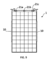
図9及び10には、上述の実施形態の何れかにおいて、各モジュール1が配電のための1つ又は複数の接続箱21a~c、22a~cを含んでいてもよいことが示されている。接続箱は、接続箱21a~cを有する図9に示されるように、モジュール1の上面、すなわち上向きの表面の上に位置付けられてよい。代替的に、接続箱は、接続箱22a~cを有する図10に示されるように、モジュール1の側面上に位置付けられてよい。代替的に、接続箱は異形材10の上に位置付けられてもよい(このケースは図示されていない)。
Figures 9 and 10 show that in any of the above-mentioned embodiments, each
有利には、接続箱をこれらの構成の1つに位置付けることによって、モジュール1とマット2との間に中断されない平面を実現できる。接続箱22a~c、23a~cは好ましくは、図9及び10からわかるように、ソーラーパネルモジュール1の側辺又は前面上に、又はそれに隣接して設置することができる。
Advantageously, by positioning the junction boxes in one of these configurations, an uninterrupted plane can be achieved between the
Claims (21)
前記マットは、取付けアセンブリによって、前記マットの上に固定された光電池モジュール(PVモジュール)を有し、
前記取付けアセンブリは、前記PVモジュールの相互に反対側にある平行な縁辺に固定された少なくとも1つの長いモジュール異形材と、前記マットに取り付けられた対応する長いマット異形材とを有し、
前記縁辺は、前記PVモジュールの側面に対応しており、
前記異形材は、
前記モジュール異形材を前記対応するマット異形材に接触させることと、
前記PVモジュールの前記縁辺に概して垂直な力を加わることによる前記2つの異形材の分離が実質的に防止される所望の最終位置に前記異形材が到達するまでに、前記モジュール異形材が固定された前記PVモジュールの前記縁辺に概して平行な方向において、前記異形材を相対的にスライドさせることと、
によって、前記PVモジュールを前記マットに固定させるように構成されている、
太陽光発電プラント。 A photovoltaic power plant comprising a flexible mat,
the mat having a photovoltaic module (PV module) secured thereon by a mounting assembly;
the mounting assembly having at least one elongated module profile secured to opposed parallel edges of the PV module and a corresponding elongated mat profile attached to the mat;
the edge corresponds to a side surface of the PV module;
The profile is
contacting the modular profile with the corresponding mat profile;
sliding the profiles relative to one another in a direction generally parallel to the edge of the PV module to which the module profile is secured until the profiles reach a desired final position that substantially prevents separation of the two profiles due to application of a force generally perpendicular to the edge of the PV module;
configured to secure the PV module to the mat by
Photovoltaic power plant.
前記ファスナは、係合するとき、前記2つの異形材が、前記PVモジュールの前記縁辺に概して平行にそれ以上相対移動しないようにする、請求項1又は2に記載の太陽光発電プラント。 A fastener is provided,
The photovoltaic power plant of claim 1 or 2, wherein the fastener, when engaged, prevents further relative movement of the two profiles generally parallel to the edge of the PV module.
前記第1保持部は、前記第1保持部が取り付けられた前記PVモジュールの前記縁辺に概して平行に延びている、請求項1~5の何れか一項に記載の太陽光発電プラント。 The modular profile has a first retention portion;
The solar power plant according to any one of claims 1 to 5, wherein the first retaining portion extends generally parallel to the edge of the PV module to which the first retaining portion is attached.
前記長いフレーム部は、基部により接続された概して平行な2つの脚を有する、請求項6に記載の太陽光発電プラント。 The first support portion is connected to the PV module by a long frame portion,
7. The photovoltaic power plant of claim 6, wherein the elongated frame section has two generally parallel legs connected by a base.
求項1~10の何れか一項に記載の太陽光発電プラント。 The photovoltaic power plant of any one of claims 1 to 10, wherein the module profile extends along the entire edge of the PV module.
前記長い第2保持部は、前記モジュール異形材の前記第1保持部と嵌合するように構成され、かつ、ウェブを介して、前記マットに固定されており、
前記ウェブは、前記マットと前記第2保持部との間の分離が前記第2保持部の実質的に全長に沿って概して一定であることを確実にする、請求項6~10の何れか一項に記載の太陽光発電プラント。 The mat profile has an elongated second retention portion,
the elongated second retaining portion is configured to mate with the first retaining portion of the module profile and is secured to the mat via a web;
The solar power plant of any one of claims 6 to 10 , wherein the web ensures that the separation between the mat and the second retaining portion is generally constant along substantially the entire length of the second retaining portion.
前記雄部は、前記第1保持部及び前記第2保持部の他方の対応する雌部に挿入されるものである、請求項12に記載の太陽光発電プラント。 One of the first retaining portion and the second retaining portion has a male portion,
The solar power plant according to claim 12 , wherein the male portion is inserted into a corresponding female portion of the other of the first holding portion and the second holding portion.
前記雌部は、前記雌部の長さ方向軸に対して平行に延びる割れ目を有する長い管を有する、請求項13に記載の太陽光発電プラント。 The male portion comprises a long tube or rod;
14. The photovoltaic power plant of claim 13, wherein the female portion comprises a long tube having a split running parallel to a longitudinal axis of the female portion.
前記モジュール異形材を前記対応するマット異形材に接触させることと、前記PVモジュールの前記縁辺に概して垂直な力を加わることによる前記2つの異形材の分離が実質的に防止される所望の最終位置に前記異形材が到達するまでに、前記モジュール異形材が固定された前記PVモジュールの前記縁辺に概して平行な方向において、前記異形材を相対的にスライドさせることと、によって、前記PVモジュールを前記マットに固定するステップを含む、
方法。 A method for installing a floating photovoltaic power plant according to any one of claims 1 to 14, comprising the steps of:
securing the PV module to the mat by contacting the module profile with the corresponding mat profile and sliding the profiles relatively in a direction generally parallel to the edge of the PV module to which the module profile is secured until the profiles reach a desired final position that substantially prevents separation of the two profiles by application of a force generally perpendicular to the edge of the PV module.
method.
前記方法は、前記モジュール異形材が固定された前記PVモジュールの前記縁辺に概して平行に前記雌部を前記雄部に対してスライドさせる前に、前記一方の異形材の前記雄部を、各対応する異形材の前記雌部の端に、前記雄部が前記雌部によって少なくとも実質的に取り囲まれるまで挿入することを含む、請求項15又は16に記載の方法。 One of the modular profiles or the mat profiles has a male retaining portion and the other profile has a female retaining portion;
17. The method of claim 15 or 16, comprising inserting the male portion of one of the profiles into an end of the female portion of each corresponding profile until the male portion is at least substantially surrounded by the female portion before sliding the female portion relative to the male portion generally parallel to the edge of the PV module to which the module profile is secured.
前記方法は、両方の前記モジュール異形材をそれらに対応するマット異形材に接触させることと、前記PVモジュールの前記縁辺に概して垂直な力を加わることによる前記2つの異形材の分離が実質的に防止される所望の最終位置に前記異形材が到達するまでに、前記モジュール異形材が固定された前記PVモジュールの前記縁辺に概して平行な方向において、前記異形材を相対的にスライドさせることと、同時に、一度に、又は逐次的に行うことによって、PVモジュールを前記マットに固定することを含む、請求項15~17の何れか一項に記載の方法。 The PV module may be provided with two module profiles secured to the edges of the PV module, and the mat may be provided with two corresponding generally parallel mat profiles;
18. The method of any one of claims 15 to 17, comprising simultaneously, simultaneously or sequentially fixing a PV module to the mat by contacting both module profiles with their corresponding mat profiles and sliding the profiles relative to one another in a direction generally parallel to the edge of the PV module to which they are fixed until the profiles reach a desired final position at which separation of the two profiles by application of a force generally perpendicular to the edge of the PV module is substantially prevented.
前記方法は、前記発電プラントを、前記下板が前記水体と直接接触するように展開することを含む、請求項19又は20に記載の方法。 The PV module includes a layer of photovoltaic cells sandwiched between a top plate and a bottom plate;
21. The method of claim 19 or 20, wherein the method comprises deploying the power plant such that the lower plate is in direct contact with the body of water.
Applications Claiming Priority (3)
| Application Number | Priority Date | Filing Date | Title |
|---|---|---|---|
| GB1813842.0A GB2576713B (en) | 2018-08-24 | 2018-08-24 | A solar power plant and method of installing a solar power plant |
| GB1813842.0 | 2018-08-24 | ||
| PCT/NO2019/050164 WO2020040643A1 (en) | 2018-08-24 | 2019-08-12 | A solar power plant and method of installing a solar power plant |
Publications (2)
| Publication Number | Publication Date |
|---|---|
| JP2021535711A JP2021535711A (en) | 2021-12-16 |
| JP7538111B2 true JP7538111B2 (en) | 2024-08-21 |
Family
ID=63715130
Family Applications (1)
| Application Number | Title | Priority Date | Filing Date |
|---|---|---|---|
| JP2021507521A Active JP7538111B2 (en) | 2018-08-24 | 2019-08-12 | Solar power plant and installation method for solar power plant |
Country Status (18)
| Country | Link |
|---|---|
| US (1) | US20210336578A1 (en) |
| EP (2) | EP3872984B1 (en) |
| JP (1) | JP7538111B2 (en) |
| KR (2) | KR102887776B1 (en) |
| CN (1) | CN112602266A (en) |
| AU (2) | AU2019324316B2 (en) |
| CL (2) | CL2021000459A1 (en) |
| EA (1) | EA202190606A1 (en) |
| ES (2) | ES2960704T3 (en) |
| GB (3) | GB2576713B (en) |
| HR (2) | HRP20240313T1 (en) |
| MX (2) | MX2021001987A (en) |
| MY (1) | MY204037A (en) |
| PH (1) | PH12021550201A1 (en) |
| SG (1) | SG11202100923UA (en) |
| UA (1) | UA128955C2 (en) |
| WO (1) | WO2020040643A1 (en) |
| ZA (2) | ZA202100725B (en) |
Families Citing this family (4)
| Publication number | Priority date | Publication date | Assignee | Title |
|---|---|---|---|---|
| US20240213916A1 (en) * | 2018-12-27 | 2024-06-27 | Solarpaint Ltd. | Conjoined Solar Module, and a Joining Unit for Conjoining Multiple Solar Panels |
| EP4479302A1 (en) | 2022-02-15 | 2024-12-25 | Ocean Sun AS | Mooring of floating photovoltaic power plants |
| CN115085663B (en) * | 2022-07-20 | 2022-12-02 | 宁波明禾新能源科技有限公司 | Integrated intelligent solar junction box |
| FR3143913B1 (en) | 2022-12-20 | 2025-03-21 | Electricite De France | Floating photovoltaic installation |
Citations (9)
| Publication number | Priority date | Publication date | Assignee | Title |
|---|---|---|---|---|
| JP2004535678A (en) | 2001-07-10 | 2004-11-25 | パワーライト・コーポレイション | Equalizing photovoltaic assembly and method |
| JP2005285969A (en) | 2004-03-29 | 2005-10-13 | Kyocera Corp | Solar cell module |
| JP2011253917A (en) | 2010-06-02 | 2011-12-15 | Mitsubishi Chemicals Corp | Solar cell film structure |
| JP2012023293A (en) | 2010-07-16 | 2012-02-02 | Fuji Electric Co Ltd | Solar cell module, solar cell module assembly, and manufacturing method therefor |
| JP2013138065A (en) | 2011-12-28 | 2013-07-11 | Taiyo Kogyo Corp | Solar cell mounting structure and method for forming the same |
| JP2013138040A (en) | 2011-11-30 | 2013-07-11 | Du Pont Kk | Installation bracket of photovoltaic power generation module |
| JP2016105472A (en) | 2014-11-20 | 2016-06-09 | 東レ株式会社 | Sheet for solar battery modules and solar battery module |
| WO2017209625A1 (en) | 2016-05-31 | 2017-12-07 | Ocean Sun As | Solar power plant |
| WO2018022655A1 (en) | 2016-07-28 | 2018-02-01 | X Development Llc | Pv module edge treatments for module-to-module interconnections |
Family Cites Families (23)
| Publication number | Priority date | Publication date | Assignee | Title |
|---|---|---|---|---|
| US4504362A (en) * | 1982-09-13 | 1985-03-12 | Kruse Clifford L | Solar desalination system and method |
| US20090223508A1 (en) * | 2008-03-05 | 2009-09-10 | Centre Suisse D'electronique Et De Microtechnique Sa | Man Made Island With Solar Energy Collection Facilities |
| KR101013316B1 (en) | 2008-01-04 | 2011-02-09 | 주식회사 케이티 | Apparatus and method for estimating subscriber age in IMS based wired / wireless hybrid network |
| CL2009000081A1 (en) * | 2008-01-15 | 2009-11-06 | Nolaris S A | Solar energy collection system consisting of a floating platform on fluid, with an external annular structure, a laminar upper cover, collector supports, air compressor and orientation system |
| US20100065106A1 (en) * | 2008-09-17 | 2010-03-18 | Barak Yekutiely | Floating water integrated photovoltaic module |
| WO2011048981A1 (en) | 2009-10-22 | 2011-04-28 | 学校法人中央大学 | Large-scale ocean mobile solar power generation system |
| DE102009060498A1 (en) * | 2009-12-23 | 2011-06-30 | Gottlieb Binder GmbH & Co. KG, 71088 | Device for fixing panel-like mats |
| US20100294331A1 (en) * | 2010-02-05 | 2010-11-25 | Carnation Richard E | Photovoltaic electrical energy generating system |
| WO2012047648A2 (en) * | 2010-09-27 | 2012-04-12 | Energy Masters, Llc | Flexible, modular, solar cell assembly |
| US8359681B2 (en) * | 2010-09-29 | 2013-01-29 | International Vectors Ltd. | Pool safety cover |
| FR2974163B1 (en) * | 2011-04-15 | 2018-06-22 | Ciel Et Terre International | PANEL SUPPORT DEVICE |
| KR101101316B1 (en) | 2011-12-05 | 2011-12-30 | 주식회사 한국피이엠 | Floating solar power plant |
| KR101382495B1 (en) * | 2013-02-22 | 2014-04-09 | 주식회사 에스에너지 | Photovoltaic module and its manufacturing method |
| KR20150018341A (en) | 2013-08-09 | 2015-02-23 | 엘에스산전 주식회사 | Supporting Device for Solar Panel |
| KR101481093B1 (en) * | 2014-06-18 | 2015-01-15 | (주)에이치에스쏠라에너지 | Floating Solar Power Generating System |
| WO2016089836A1 (en) * | 2014-12-01 | 2016-06-09 | 4CSOLAR, Inc. | Floating solar panel systems |
| EP3276824A4 (en) * | 2015-03-25 | 2018-10-31 | Zeon Corporation | Photoelectric conversion device |
| US9515600B2 (en) * | 2015-05-04 | 2016-12-06 | Solarworld Americas Inc. | Solar module installation system and method |
| KR101612832B1 (en) | 2015-08-07 | 2016-04-15 | 주식회사 더블유쏠라 | Appatus of solar power plant |
| KR101636654B1 (en) * | 2015-09-10 | 2016-07-05 | 전북대학교산학협력단 | Sunlight module on the water |
| US20170279402A1 (en) * | 2016-03-25 | 2017-09-28 | X Development Llc | Photovoltaic macro-module for solar power generation |
| US20170310272A1 (en) * | 2016-04-25 | 2017-10-26 | Google Inc. | Floating photovoltaic power generation system |
| ES2955228T3 (en) * | 2017-03-10 | 2023-11-29 | Romande Energie Sa | sun mat |
-
2018
- 2018-08-24 GB GB1813842.0A patent/GB2576713B/en active Active
- 2018-11-08 GB GB1818231.1A patent/GB2576794B/en active Active
-
2019
- 2019-08-12 EP EP21168979.9A patent/EP3872984B1/en active Active
- 2019-08-12 JP JP2021507521A patent/JP7538111B2/en active Active
- 2019-08-12 US US17/269,354 patent/US20210336578A1/en not_active Abandoned
- 2019-08-12 UA UAA202101512A patent/UA128955C2/en unknown
- 2019-08-12 MY MYPI2021000742A patent/MY204037A/en unknown
- 2019-08-12 ES ES19766116T patent/ES2960704T3/en active Active
- 2019-08-12 SG SG11202100923UA patent/SG11202100923UA/en unknown
- 2019-08-12 HR HRP20240313TT patent/HRP20240313T1/en unknown
- 2019-08-12 GB GB2003868.3A patent/GB2579333A/en not_active Withdrawn
- 2019-08-12 WO PCT/NO2019/050164 patent/WO2020040643A1/en not_active Ceased
- 2019-08-12 HR HRP20231293TT patent/HRP20231293T1/en unknown
- 2019-08-12 CN CN201980055725.1A patent/CN112602266A/en active Pending
- 2019-08-12 KR KR1020217008790A patent/KR102887776B1/en active Active
- 2019-08-12 KR KR1020257038141A patent/KR20250168684A/en active Pending
- 2019-08-12 MX MX2021001987A patent/MX2021001987A/en unknown
- 2019-08-12 ES ES21168979T patent/ES2974071T3/en active Active
- 2019-08-12 EA EA202190606A patent/EA202190606A1/en unknown
- 2019-08-12 AU AU2019324316A patent/AU2019324316B2/en active Active
- 2019-08-12 EP EP19766116.8A patent/EP3841663B1/en active Active
-
2021
- 2021-01-27 PH PH12021550201A patent/PH12021550201A1/en unknown
- 2021-02-02 ZA ZA2021/00725A patent/ZA202100725B/en unknown
- 2021-02-18 MX MX2024012917A patent/MX2024012917A/en unknown
- 2021-02-24 CL CL2021000459A patent/CL2021000459A1/en unknown
-
2022
- 2022-05-03 ZA ZA2022/04842A patent/ZA202204842B/en unknown
-
2023
- 2023-02-17 CL CL2023000488A patent/CL2023000488A1/en unknown
-
2024
- 2024-01-17 AU AU2024200320A patent/AU2024200320B2/en active Active
Patent Citations (9)
| Publication number | Priority date | Publication date | Assignee | Title |
|---|---|---|---|---|
| JP2004535678A (en) | 2001-07-10 | 2004-11-25 | パワーライト・コーポレイション | Equalizing photovoltaic assembly and method |
| JP2005285969A (en) | 2004-03-29 | 2005-10-13 | Kyocera Corp | Solar cell module |
| JP2011253917A (en) | 2010-06-02 | 2011-12-15 | Mitsubishi Chemicals Corp | Solar cell film structure |
| JP2012023293A (en) | 2010-07-16 | 2012-02-02 | Fuji Electric Co Ltd | Solar cell module, solar cell module assembly, and manufacturing method therefor |
| JP2013138040A (en) | 2011-11-30 | 2013-07-11 | Du Pont Kk | Installation bracket of photovoltaic power generation module |
| JP2013138065A (en) | 2011-12-28 | 2013-07-11 | Taiyo Kogyo Corp | Solar cell mounting structure and method for forming the same |
| JP2016105472A (en) | 2014-11-20 | 2016-06-09 | 東レ株式会社 | Sheet for solar battery modules and solar battery module |
| WO2017209625A1 (en) | 2016-05-31 | 2017-12-07 | Ocean Sun As | Solar power plant |
| WO2018022655A1 (en) | 2016-07-28 | 2018-02-01 | X Development Llc | Pv module edge treatments for module-to-module interconnections |
Also Published As
Similar Documents
| Publication | Publication Date | Title |
|---|---|---|
| JP7555451B2 (en) | Solar power generation facilities | |
| AU2024200320B2 (en) | A solar power plant and method of installing a solar power plant | |
| CA3107752C (en) | A solar power plant and method of installing a solar power plant | |
| HK40056941A (en) | A solar power plant | |
| HK40056941B (en) | A solar power plant | |
| EA041097B1 (en) | SOLAR POWER PLANT AND METHOD OF INSTALLING SOLAR POWER PLANT | |
| HK40045247B (en) | A solar power plant and method of installing a solar power plant | |
| HK40045247A (en) | A solar power plant and method of installing a solar power plant | |
| BR122022016013B1 (en) | SOLAR POWER PLANT | |
| BR112021002971B1 (en) | SOLAR POWER PLANT AND METHOD FOR INSTALLING A FLOATING PHOTOVOLTAIC POWER PLANT | |
| HK40052924B (en) | Solar power plant | |
| EA036603B1 (en) | Solar power plant |
Legal Events
| Date | Code | Title | Description |
|---|---|---|---|
| A621 | Written request for application examination |
Free format text: JAPANESE INTERMEDIATE CODE: A621 Effective date: 20220704 |
|
| A977 | Report on retrieval |
Free format text: JAPANESE INTERMEDIATE CODE: A971007 Effective date: 20230316 |
|
| A131 | Notification of reasons for refusal |
Free format text: JAPANESE INTERMEDIATE CODE: A131 Effective date: 20230502 |
|
| A521 | Request for written amendment filed |
Free format text: JAPANESE INTERMEDIATE CODE: A523 Effective date: 20230731 |
|
| A02 | Decision of refusal |
Free format text: JAPANESE INTERMEDIATE CODE: A02 Effective date: 20231101 |
|
| A521 | Request for written amendment filed |
Free format text: JAPANESE INTERMEDIATE CODE: A523 Effective date: 20240229 |
|
| A521 | Request for written amendment filed |
Free format text: JAPANESE INTERMEDIATE CODE: A821 Effective date: 20240313 |
|
| A911 | Transfer to examiner for re-examination before appeal (zenchi) |
Free format text: JAPANESE INTERMEDIATE CODE: A911 Effective date: 20240410 |
|
| TRDD | Decision of grant or rejection written | ||
| A01 | Written decision to grant a patent or to grant a registration (utility model) |
Free format text: JAPANESE INTERMEDIATE CODE: A01 Effective date: 20240730 |
|
| A61 | First payment of annual fees (during grant procedure) |
Free format text: JAPANESE INTERMEDIATE CODE: A61 Effective date: 20240808 |
|
| R150 | Certificate of patent or registration of utility model |
Ref document number: 7538111 Country of ref document: JP Free format text: JAPANESE INTERMEDIATE CODE: R150 |