JP7539775B2 - 電気機械素子および電気機械 - Google Patents
電気機械素子および電気機械 Download PDFInfo
- Publication number
- JP7539775B2 JP7539775B2 JP2020030154A JP2020030154A JP7539775B2 JP 7539775 B2 JP7539775 B2 JP 7539775B2 JP 2020030154 A JP2020030154 A JP 2020030154A JP 2020030154 A JP2020030154 A JP 2020030154A JP 7539775 B2 JP7539775 B2 JP 7539775B2
- Authority
- JP
- Japan
- Prior art keywords
- phase
- phase winding
- winding
- electromechanical element
- electromechanical
- Prior art date
- Legal status (The legal status is an assumption and is not a legal conclusion. Google has not performed a legal analysis and makes no representation as to the accuracy of the status listed.)
- Active
Links
Images




Classifications
-
- H—ELECTRICITY
- H02—GENERATION; CONVERSION OR DISTRIBUTION OF ELECTRIC POWER
- H02P—CONTROL OR REGULATION OF ELECTRIC MOTORS, ELECTRIC GENERATORS OR DYNAMO-ELECTRIC CONVERTERS; CONTROLLING TRANSFORMERS, REACTORS OR CHOKE COILS
- H02P25/00—Arrangements or methods for the control of AC motors characterised by the kind of AC motor or by structural details
- H02P25/16—Arrangements or methods for the control of AC motors characterised by the kind of AC motor or by structural details characterised by the circuit arrangement or by the kind of wiring
-
- H—ELECTRICITY
- H02—GENERATION; CONVERSION OR DISTRIBUTION OF ELECTRIC POWER
- H02K—DYNAMO-ELECTRIC MACHINES
- H02K1/00—Details of the magnetic circuit
- H02K1/06—Details of the magnetic circuit characterised by the shape, form or construction
- H02K1/12—Stationary parts of the magnetic circuit
- H02K1/16—Stator cores with slots for windings
-
- H—ELECTRICITY
- H02—GENERATION; CONVERSION OR DISTRIBUTION OF ELECTRIC POWER
- H02K—DYNAMO-ELECTRIC MACHINES
- H02K1/00—Details of the magnetic circuit
- H02K1/06—Details of the magnetic circuit characterised by the shape, form or construction
- H02K1/12—Stationary parts of the magnetic circuit
- H02K1/16—Stator cores with slots for windings
- H02K1/165—Shape, form or location of the slots
-
- H—ELECTRICITY
- H02—GENERATION; CONVERSION OR DISTRIBUTION OF ELECTRIC POWER
- H02K—DYNAMO-ELECTRIC MACHINES
- H02K1/00—Details of the magnetic circuit
- H02K1/06—Details of the magnetic circuit characterised by the shape, form or construction
- H02K1/22—Rotating parts of the magnetic circuit
- H02K1/27—Rotor cores with permanent magnets
-
- H—ELECTRICITY
- H02—GENERATION; CONVERSION OR DISTRIBUTION OF ELECTRIC POWER
- H02K—DYNAMO-ELECTRIC MACHINES
- H02K1/00—Details of the magnetic circuit
- H02K1/06—Details of the magnetic circuit characterised by the shape, form or construction
- H02K1/22—Rotating parts of the magnetic circuit
- H02K1/27—Rotor cores with permanent magnets
- H02K1/2706—Inner rotors
-
- H—ELECTRICITY
- H02—GENERATION; CONVERSION OR DISTRIBUTION OF ELECTRIC POWER
- H02K—DYNAMO-ELECTRIC MACHINES
- H02K21/00—Synchronous motors having permanent magnets; Synchronous generators having permanent magnets
- H02K21/02—Details
- H02K21/10—Rotating armatures
-
- H—ELECTRICITY
- H02—GENERATION; CONVERSION OR DISTRIBUTION OF ELECTRIC POWER
- H02K—DYNAMO-ELECTRIC MACHINES
- H02K21/00—Synchronous motors having permanent magnets; Synchronous generators having permanent magnets
- H02K21/12—Synchronous motors having permanent magnets; Synchronous generators having permanent magnets with stationary armatures and rotating magnets
- H02K21/14—Synchronous motors having permanent magnets; Synchronous generators having permanent magnets with stationary armatures and rotating magnets with magnets rotating within the armatures
-
- H—ELECTRICITY
- H02—GENERATION; CONVERSION OR DISTRIBUTION OF ELECTRIC POWER
- H02K—DYNAMO-ELECTRIC MACHINES
- H02K3/00—Details of windings
- H02K3/04—Windings characterised by the conductor shape, form or construction, e.g. with bar conductors
- H02K3/12—Windings characterised by the conductor shape, form or construction, e.g. with bar conductors arranged in slots
-
- H—ELECTRICITY
- H02—GENERATION; CONVERSION OR DISTRIBUTION OF ELECTRIC POWER
- H02K—DYNAMO-ELECTRIC MACHINES
- H02K3/00—Details of windings
- H02K3/04—Windings characterised by the conductor shape, form or construction, e.g. with bar conductors
- H02K3/28—Layout of windings or of connections between windings
-
- H—ELECTRICITY
- H02—GENERATION; CONVERSION OR DISTRIBUTION OF ELECTRIC POWER
- H02K—DYNAMO-ELECTRIC MACHINES
- H02K3/00—Details of windings
- H02K3/46—Fastening of windings on the stator or rotor structure
- H02K3/48—Fastening of windings on the stator or rotor structure in slots
-
- H—ELECTRICITY
- H02—GENERATION; CONVERSION OR DISTRIBUTION OF ELECTRIC POWER
- H02K—DYNAMO-ELECTRIC MACHINES
- H02K3/00—Details of windings
- H02K3/46—Fastening of windings on the stator or rotor structure
- H02K3/50—Fastening of winding heads, equalising connectors, or connections thereto
-
- H—ELECTRICITY
- H02—GENERATION; CONVERSION OR DISTRIBUTION OF ELECTRIC POWER
- H02P—CONTROL OR REGULATION OF ELECTRIC MOTORS, ELECTRIC GENERATORS OR DYNAMO-ELECTRIC CONVERTERS; CONTROLLING TRANSFORMERS, REACTORS OR CHOKE COILS
- H02P25/00—Arrangements or methods for the control of AC motors characterised by the kind of AC motor or by structural details
- H02P25/16—Arrangements or methods for the control of AC motors characterised by the kind of AC motor or by structural details characterised by the circuit arrangement or by the kind of wiring
- H02P25/18—Arrangements or methods for the control of AC motors characterised by the kind of AC motor or by structural details characterised by the circuit arrangement or by the kind of wiring with arrangements for switching the windings, e.g. with mechanical switches or relays
Landscapes
- Engineering & Computer Science (AREA)
- Power Engineering (AREA)
- Windings For Motors And Generators (AREA)
- Synchronous Machinery (AREA)
Description
-電気機械素子の外部の交流システムに接続するための電気端子と、
-前記電気端子に接続され、各々が第1の端部および第2の端部を有する相巻線を各々含む、少なくとも2つの多相巻線部分を含む、少なくとも1つの多相巻線と、
を備える。
以下の説明で提供される特定の実施例は、添付の特許請求の範囲および/または適用可能性を制限するものとして解釈されるべきではない。説明で提供されている実施例の表および群は、特に明記されていない限り網羅的ではない。
R1=NL/((A1/N)δf) (1)
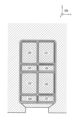
式中、Lは、スロットの軸方向の長さ、つまり座標系199のz方向の長さであり、A1は、直列接続された導電体120~123が占める断面積であり、δは、導電性材料の導電率であり、fは、スロットの断面積Aに対する導電性材料の充填率であり、Nは、スロット内の直列接続された導電体120~123の数である。この例示の場合では、N=4である。
R2=NL/(A2/N)δf) (2)
式中、A2は、直列接続された導電体124~127が占める断面積である。簡単にするために、スロット内の直列接続された導電体124~127の数は、スロット内の直列接続された導電体120~123の数Nと同じである。
NI1=2NI2 (3)
の場合、図1bおよび図1cに示される両方の状況で同じであり、
式中、I1は、図1bに示される状況の固定子電流であり、I2は、図1cに示される状況の固定子電流である。スロット内の抵抗損失は、
I1 2R1=I2 2(R1+R2) (4)
の場合、図1bおよび図1cに示される両方の状況で同じであり、
式中、R1+R2は、直列接続された導電体120~127すべての抵抗である。
式1~3を式4に代入すると、
4/A1=1/A1+1/A2=(A1+A2)/(A1A2)=A/(A1A2) (5)
となり、
A2=A/4およびA1=3A/4となる。したがって、この例示の場合では、スロットの断面積Aの75%は、多相巻線部分103に割り当てられ、スロットの断面積Aの25%は、多相巻線部分104に割り当てられる。したがって、この例示の場合では、多相巻線部分103の相巻線の各巻線の導体断面積は、多相巻線部分104の相巻線の各巻線の導体断面積の3倍である。 また、例えば、図1bおよび図1cに示される状況に関連する性能要件、および/または多相巻線部分の異なる部分に関連するコイル巻数間の比率などの要因に応じて、異なる導体断面積比を使用することも可能である。
102 多相巻線
103,104 多相巻線部分
106a,106b,106c 相巻線
107a,107b,107c 相巻線
109 第1の端部
110 第2の端部
111 第1の端部
112 第2の端部
113a,113b,113c 相巻線の鎖
114a,114b,115a,115b スイッチ
120~127 導電体
130 交流システム
131 永久磁石機械
199 座標系
201 電気端子
202,204 多相巻線
203~205 多相巻線部分
213a,213b,213c 相巻線の鎖
214a,214b,215a,215b スイッチ
216a,216b スイッチ
300 第1の機械素子
302 多相巻線
314a,314b,315a,315b スイッチ
317 コア構造
318 第2の機械素子
Claims (13)
- 電気機械素子(300)であって、
-前記電気機械素子の外部の交流システムに接続するための電気端子(101、201、301)と、
-前記電気端子に接続され、各々が第1の端部(109、111)および第2の端部(110、112)を有する相巻線(106a~106c、107a~107c)を各々含む、少なくとも2つの多相巻線部分(103、104、203~205)を含む、少なくとも1つの多相巻線(102、202、302)と、
-コア構造(317)に設けられ、前記多相巻線部分の前記相巻線を含むスロットと、
を備え、
前記多相巻線部分は、前記多相巻線の各位相が、考慮中の前記位相に属する前記相巻線の鎖(113a~113c、213a~213c)であるように、互いに連続して接続され、そのため、考慮中の前記位相に属する前記各相巻線の第2の端部から、考慮中の前記位相に属する前記電気端子の1つまでの電流経路は、考慮中の少なくとも前記相巻線を含み、
前記各多相巻線部分は、考慮中の前記多相巻線部分の前記相巻線の前記第2の端部を互いに接続するためのスイッチ(114a、114b、115a、115b、214a、214b、215a、215b、216a、216b、314a、314b、315a、315b)を含み、
前記スロットは、前記多相巻線部分の第1の部分(103)に割り当てられる第1断面部分と、前記多相巻線部分の第2の部分(104)に割り当てられる第2断面部分と、を備え、
前記第1断面部分に通電可能であり、
前記第2断面部分に前記第1断面部分と同時に通電可能であり、
前記多相巻線部分の前記第1の部分(103)の前記相巻線の各巻線の導体断面積は、前記多相巻線部分の前記第2の部分(104)の前記相巻線の各巻線の導体断面積よりも大きい、
ことを特徴とする、電気機械素子。 - 前記各多相巻線部分のスイッチ(114a、114b、115a、115b、214a、214b、215a、215b、216a、216b)は、考慮中の前記多相巻線部分の前記スイッチの数が前記多相巻線の前記位相の数よりも1つ少なくなるように、考慮中の前記多相巻線部分の前記相巻線(106a~106c、107a~107c)の前記第2の端部間に接続される、請求項1に記載の電気機械素子。
- 前記多相巻線部分の前記第1の部分(103)は、前記電気端子(101)と、前記多相巻線部分の前記第2の部分(104)との間にある、請求項1または2に記載の電気機械素子。
- 前記多相巻線部分すべての前記相巻線部分は、同じ巻数を有する、請求項1から3のいずれか一項に記載の電気機械素子。
- 前記多相巻線部分の前記第1の部分(103)の各相巻線の巻数は、前記多相巻線部分の前記第2の部分(104)の各相巻線の巻数よりも少ない、請求項1から3のいずれか一項に記載の電気機械素子。
- 前記多相巻線部分の前記第2の部分の前記各相巻線の巻数は、前記多相巻線部分の前記第1の部分の前記各相巻線の巻数の少なくとも2倍である、請求項5に記載の電気機械素子。
- 前記多相巻線部分の前記第2の部分の前記各相巻線の巻数は、前記多相巻線部分の前記第1の部分の前記各相巻線の巻数の少なくとも3倍である、請求項6に記載の電気機械素子。
- 前記多相巻線部分の前記第1の部分は、前記電気端子と、前記多相巻線部分の前記第2の部分との間にある、請求項5から7のいずれか一項に記載の電気機械素子。
- 前記電気機械素子(300)は、交流電気機械の固定子の一部である、請求項1から8のいずれか一項に記載の電気機械素子。
- 前記電気機械素子(300)は、内部回転子型交流電気機械の固定子の一部である、請求項1から9のいずれか一項に記載の電気機械素子。
- 互いに対して回転可能に支持されている第1および第2の機械素子(300、318)を含む電気機械であって、前記第1の機械素子は、請求項1から10のいずれか一項に記載の電気機械素子である、電気機械。
- 前記第2の機械素子(318)は、前記第1の機械素子と相互作用する磁束を作り出すための永久磁石材料を含む、請求項11に記載の電気機械。
- 前記第1の機械素子(300)は、前記電気機械の固定子の一部であり、前記第2の機械素子(318)は、前記電気機械の回転子である、請求項11または12のいずれか一項に記載の電気機械。
Applications Claiming Priority (2)
| Application Number | Priority Date | Filing Date | Title |
|---|---|---|---|
| EP19168692.2 | 2019-04-11 | ||
| EP19168692.2A EP3723276B1 (en) | 2019-04-11 | 2019-04-11 | An electric machine element and an electric machine |
Publications (2)
| Publication Number | Publication Date |
|---|---|
| JP2020174513A JP2020174513A (ja) | 2020-10-22 |
| JP7539775B2 true JP7539775B2 (ja) | 2024-08-26 |
Family
ID=66105212
Family Applications (1)
| Application Number | Title | Priority Date | Filing Date |
|---|---|---|---|
| JP2020030154A Active JP7539775B2 (ja) | 2019-04-11 | 2020-02-26 | 電気機械素子および電気機械 |
Country Status (6)
| Country | Link |
|---|---|
| US (1) | US11394265B2 (ja) |
| EP (1) | EP3723276B1 (ja) |
| JP (1) | JP7539775B2 (ja) |
| KR (1) | KR102858315B1 (ja) |
| CN (1) | CN111817466B (ja) |
| FI (1) | FI3723276T3 (ja) |
Families Citing this family (4)
| Publication number | Priority date | Publication date | Assignee | Title |
|---|---|---|---|---|
| EP4009514B1 (en) | 2020-12-04 | 2023-12-27 | Danfoss A/S | A converter and a method for driving an electric machine and computer program |
| WO2022195554A1 (en) * | 2021-03-18 | 2022-09-22 | Caleb Innovations Inc. | Reducible parallel conversion |
| DE102021212413A1 (de) * | 2021-11-04 | 2023-05-04 | Valeo Eautomotive Germany Gmbh | Elektrischer Antrieb mit einer elektrischen Maschine mit Sternpunktumschaltung |
| US20240421647A1 (en) * | 2021-12-24 | 2024-12-19 | Autonetworks Technologies, Ltd. | Stator |
Citations (10)
| Publication number | Priority date | Publication date | Assignee | Title |
|---|---|---|---|---|
| JP2003111492A (ja) | 2001-10-03 | 2003-04-11 | Yaskawa Electric Corp | 3相交流電動機の巻線切換装置 |
| JP2006141143A (ja) | 2004-11-12 | 2006-06-01 | Kokusan Denki Co Ltd | バッテリ充電装置 |
| US20120068657A1 (en) | 2010-09-20 | 2012-03-22 | Remy Technologies, L.L.C. | Electric machine system including an electric machine having switched stator windings |
| US20120306424A1 (en) | 2011-06-02 | 2012-12-06 | GM Global Technology Operations LLC | Electric drive with electronically scalable reconfigurable winding |
| US20130127391A1 (en) | 2010-03-17 | 2013-05-23 | GE ENERGY POWER CONVERSION TECHNOLOGY LTD. (formerly Converteam Technology Ltd.) | Electrical machines |
| JP2013121222A (ja) | 2011-12-07 | 2013-06-17 | Hitachi Appliances Inc | モータ駆動装置、およびこれを用いた機器 |
| JP2013162615A (ja) | 2012-02-03 | 2013-08-19 | Yaskawa Electric Corp | 回転電機システム |
| JP2017093097A (ja) | 2015-11-06 | 2017-05-25 | 株式会社デンソー | 回転電機 |
| JP2017112676A (ja) | 2015-12-15 | 2017-06-22 | 三菱重工業株式会社 | モータの巻線切替スイッチを備えたモータ用駆動制御装置、モータ、コンプレッサ、およびモータ巻線切替制御方法 |
| CN108448873A (zh) | 2018-03-21 | 2018-08-24 | 哈尔滨工业大学 | 超导磁悬浮直线电磁推进系统 |
Family Cites Families (3)
| Publication number | Priority date | Publication date | Assignee | Title |
|---|---|---|---|---|
| JPS5518826A (en) * | 1978-07-27 | 1980-02-09 | Toshiba Corp | Pole change type revolving-machine and operation method |
| JP2016171607A (ja) * | 2015-03-11 | 2016-09-23 | 日立アプライアンス株式会社 | 永久磁石同期機、モータ駆動システムおよび電気機器 |
| JP2020018826A (ja) * | 2018-07-24 | 2020-02-06 | 株式会社高尾 | 弾球遊技機 |
-
2019
- 2019-04-11 EP EP19168692.2A patent/EP3723276B1/en active Active
- 2019-04-11 FI FIEP19168692.2T patent/FI3723276T3/fi active
-
2020
- 2020-02-26 JP JP2020030154A patent/JP7539775B2/ja active Active
- 2020-03-11 KR KR1020200030103A patent/KR102858315B1/ko active Active
- 2020-03-27 CN CN202010231188.6A patent/CN111817466B/zh active Active
- 2020-04-02 US US16/838,195 patent/US11394265B2/en active Active
Patent Citations (10)
| Publication number | Priority date | Publication date | Assignee | Title |
|---|---|---|---|---|
| JP2003111492A (ja) | 2001-10-03 | 2003-04-11 | Yaskawa Electric Corp | 3相交流電動機の巻線切換装置 |
| JP2006141143A (ja) | 2004-11-12 | 2006-06-01 | Kokusan Denki Co Ltd | バッテリ充電装置 |
| US20130127391A1 (en) | 2010-03-17 | 2013-05-23 | GE ENERGY POWER CONVERSION TECHNOLOGY LTD. (formerly Converteam Technology Ltd.) | Electrical machines |
| US20120068657A1 (en) | 2010-09-20 | 2012-03-22 | Remy Technologies, L.L.C. | Electric machine system including an electric machine having switched stator windings |
| US20120306424A1 (en) | 2011-06-02 | 2012-12-06 | GM Global Technology Operations LLC | Electric drive with electronically scalable reconfigurable winding |
| JP2013121222A (ja) | 2011-12-07 | 2013-06-17 | Hitachi Appliances Inc | モータ駆動装置、およびこれを用いた機器 |
| JP2013162615A (ja) | 2012-02-03 | 2013-08-19 | Yaskawa Electric Corp | 回転電機システム |
| JP2017093097A (ja) | 2015-11-06 | 2017-05-25 | 株式会社デンソー | 回転電機 |
| JP2017112676A (ja) | 2015-12-15 | 2017-06-22 | 三菱重工業株式会社 | モータの巻線切替スイッチを備えたモータ用駆動制御装置、モータ、コンプレッサ、およびモータ巻線切替制御方法 |
| CN108448873A (zh) | 2018-03-21 | 2018-08-24 | 哈尔滨工业大学 | 超导磁悬浮直线电磁推进系统 |
Also Published As
| Publication number | Publication date |
|---|---|
| EP3723276A1 (en) | 2020-10-14 |
| KR102858315B1 (ko) | 2025-09-10 |
| US20200328645A1 (en) | 2020-10-15 |
| KR20200120866A (ko) | 2020-10-22 |
| EP3723276B1 (en) | 2023-06-07 |
| CN111817466B (zh) | 2023-08-04 |
| FI3723276T3 (fi) | 2023-09-01 |
| US11394265B2 (en) | 2022-07-19 |
| CN111817466A (zh) | 2020-10-23 |
| JP2020174513A (ja) | 2020-10-22 |
Similar Documents
| Publication | Publication Date | Title |
|---|---|---|
| JP7539775B2 (ja) | 電気機械素子および電気機械 | |
| US11502567B2 (en) | Stator winding for a rotating electrical machine | |
| US20140062269A1 (en) | Dc electrical machines | |
| KR101247085B1 (ko) | 유도 모터 회로용 두 전도체 권선 | |
| US20130221791A1 (en) | Rotary electric machine system | |
| US9240707B2 (en) | Rotary electric machine | |
| CN107251410A (zh) | 永磁体型双三相电动机及电动助力转向装置 | |
| CN110402530B (zh) | 驱动装置 | |
| JP5864127B2 (ja) | 巻線装置、電機子、風力タービン、および巻線装置の使用方法 | |
| CN107070016A (zh) | 双余度定子及双余度电机 | |
| KR20130028919A (ko) | 전기 기기의 보호 회로 및 보호 방법 | |
| EP3826147A1 (en) | Multiple winding electrical machine for an aircraft | |
| CN111919363B (zh) | 交流电机与变流器单元的组合和风力发电设备 | |
| WO2016015909A1 (en) | Method of connecting a power converter to an electrical machine and a power system comprising a power converter and an electrical machine | |
| JP7188627B1 (ja) | 回転電機 | |
| CN110867994B (zh) | 旋转电机 | |
| JP5055937B2 (ja) | 回転電機の巻線絶縁構造 | |
| CN112753152B (zh) | 多相旋转电机的磁性有源单元 | |
| CN102498641B (zh) | 电枢绕组 | |
| EP2800248B1 (en) | Stator winding of an electric generator | |
| EP3625875B1 (en) | Electric motor and winding method | |
| JP2024003667A (ja) | ステータ及びモータ | |
| JP2009303389A (ja) | ブラシ付モータ | |
| CN119343852A (zh) | 多绕组组分数槽同步机器 | |
| JP2022146205A (ja) | ステータ及び回転電機 |
Legal Events
| Date | Code | Title | Description |
|---|---|---|---|
| A621 | Written request for application examination |
Free format text: JAPANESE INTERMEDIATE CODE: A621 Effective date: 20230227 |
|
| A977 | Report on retrieval |
Free format text: JAPANESE INTERMEDIATE CODE: A971007 Effective date: 20240131 |
|
| A131 | Notification of reasons for refusal |
Free format text: JAPANESE INTERMEDIATE CODE: A131 Effective date: 20240206 |
|
| A711 | Notification of change in applicant |
Free format text: JAPANESE INTERMEDIATE CODE: A711 Effective date: 20240315 |
|
| RD03 | Notification of appointment of power of attorney |
Free format text: JAPANESE INTERMEDIATE CODE: A7423 Effective date: 20240321 |
|
| RD04 | Notification of resignation of power of attorney |
Free format text: JAPANESE INTERMEDIATE CODE: A7424 Effective date: 20240419 |
|
| A521 | Request for written amendment filed |
Free format text: JAPANESE INTERMEDIATE CODE: A523 Effective date: 20240501 |
|
| A131 | Notification of reasons for refusal |
Free format text: JAPANESE INTERMEDIATE CODE: A131 Effective date: 20240611 |
|
| A521 | Request for written amendment filed |
Free format text: JAPANESE INTERMEDIATE CODE: A523 Effective date: 20240724 |
|
| TRDD | Decision of grant or rejection written | ||
| A01 | Written decision to grant a patent or to grant a registration (utility model) |
Free format text: JAPANESE INTERMEDIATE CODE: A01 Effective date: 20240806 |
|
| A61 | First payment of annual fees (during grant procedure) |
Free format text: JAPANESE INTERMEDIATE CODE: A61 Effective date: 20240814 |
|
| R150 | Certificate of patent or registration of utility model |
Ref document number: 7539775 Country of ref document: JP Free format text: JAPANESE INTERMEDIATE CODE: R150 |