JP7542013B2 - 電気負荷に電力を供給するためのコンバータ - Google Patents
電気負荷に電力を供給するためのコンバータ Download PDFInfo
- Publication number
- JP7542013B2 JP7542013B2 JP2021571739A JP2021571739A JP7542013B2 JP 7542013 B2 JP7542013 B2 JP 7542013B2 JP 2021571739 A JP2021571739 A JP 2021571739A JP 2021571739 A JP2021571739 A JP 2021571739A JP 7542013 B2 JP7542013 B2 JP 7542013B2
- Authority
- JP
- Japan
- Prior art keywords
- active switch
- voltage
- electrical
- terminal
- resonant
- Prior art date
- Legal status (The legal status is an assumption and is not a legal conclusion. Google has not performed a legal analysis and makes no representation as to the accuracy of the status listed.)
- Active
Links
- 230000008878 coupling Effects 0.000 claims description 32
- 238000010168 coupling process Methods 0.000 claims description 32
- 238000005859 coupling reaction Methods 0.000 claims description 32
- 229920006395 saturated elastomer Polymers 0.000 claims description 14
- 230000000903 blocking effect Effects 0.000 claims description 3
- 230000008901 benefit Effects 0.000 description 19
- 230000005291 magnetic effect Effects 0.000 description 13
- 230000001939 inductive effect Effects 0.000 description 12
- 230000001965 increasing effect Effects 0.000 description 11
- 239000000696 magnetic material Substances 0.000 description 10
- 230000010355 oscillation Effects 0.000 description 10
- 238000010586 diagram Methods 0.000 description 8
- 230000000694 effects Effects 0.000 description 8
- 238000012546 transfer Methods 0.000 description 8
- 230000006870 function Effects 0.000 description 7
- 230000004907 flux Effects 0.000 description 6
- 230000007423 decrease Effects 0.000 description 5
- 238000002955 isolation Methods 0.000 description 5
- 230000001360 synchronised effect Effects 0.000 description 5
- 230000009467 reduction Effects 0.000 description 4
- 230000007704 transition Effects 0.000 description 4
- 230000008859 change Effects 0.000 description 3
- 230000006698 induction Effects 0.000 description 3
- 238000000034 method Methods 0.000 description 3
- 230000035699 permeability Effects 0.000 description 3
- 230000003068 static effect Effects 0.000 description 3
- 230000004888 barrier function Effects 0.000 description 2
- 230000033228 biological regulation Effects 0.000 description 2
- 238000004891 communication Methods 0.000 description 2
- 238000011161 development Methods 0.000 description 2
- 230000002500 effect on skin Effects 0.000 description 2
- 238000012986 modification Methods 0.000 description 2
- 230000004048 modification Effects 0.000 description 2
- 230000003287 optical effect Effects 0.000 description 2
- 230000000737 periodic effect Effects 0.000 description 2
- 230000008092 positive effect Effects 0.000 description 2
- 230000004044 response Effects 0.000 description 2
- 238000004804 winding Methods 0.000 description 2
- 239000010754 BS 2869 Class F Substances 0.000 description 1
- 230000005540 biological transmission Effects 0.000 description 1
- 239000003990 capacitor Substances 0.000 description 1
- 239000003638 chemical reducing agent Substances 0.000 description 1
- 239000002131 composite material Substances 0.000 description 1
- 238000010276 construction Methods 0.000 description 1
- 230000001934 delay Effects 0.000 description 1
- 230000003111 delayed effect Effects 0.000 description 1
- 230000001419 dependent effect Effects 0.000 description 1
- 238000013461 design Methods 0.000 description 1
- 238000004146 energy storage Methods 0.000 description 1
- 238000005516 engineering process Methods 0.000 description 1
- 239000003302 ferromagnetic material Substances 0.000 description 1
- 230000005669 field effect Effects 0.000 description 1
- 238000001914 filtration Methods 0.000 description 1
- 238000009413 insulation Methods 0.000 description 1
- 239000000463 material Substances 0.000 description 1
- 238000005259 measurement Methods 0.000 description 1
- 239000011858 nanopowder Substances 0.000 description 1
- 230000007935 neutral effect Effects 0.000 description 1
- 230000010363 phase shift Effects 0.000 description 1
- 230000001105 regulatory effect Effects 0.000 description 1
- 238000004904 shortening Methods 0.000 description 1
- 238000004513 sizing Methods 0.000 description 1
- 230000001052 transient effect Effects 0.000 description 1
Images





Classifications
-
- H—ELECTRICITY
- H02—GENERATION; CONVERSION OR DISTRIBUTION OF ELECTRIC POWER
- H02M—APPARATUS FOR CONVERSION BETWEEN AC AND AC, BETWEEN AC AND DC, OR BETWEEN DC AND DC, AND FOR USE WITH MAINS OR SIMILAR POWER SUPPLY SYSTEMS; CONVERSION OF DC OR AC INPUT POWER INTO SURGE OUTPUT POWER; CONTROL OR REGULATION THEREOF
- H02M3/00—Conversion of DC power input into DC power output
- H02M3/02—Conversion of DC power input into DC power output without intermediate conversion into AC
- H02M3/04—Conversion of DC power input into DC power output without intermediate conversion into AC by static converters
- H02M3/10—Conversion of DC power input into DC power output without intermediate conversion into AC by static converters using discharge tubes with control electrode or semiconductor devices with control electrode
- H02M3/145—Conversion of DC power input into DC power output without intermediate conversion into AC by static converters using discharge tubes with control electrode or semiconductor devices with control electrode using devices of a triode or transistor type requiring continuous application of a control signal
- H02M3/155—Conversion of DC power input into DC power output without intermediate conversion into AC by static converters using discharge tubes with control electrode or semiconductor devices with control electrode using devices of a triode or transistor type requiring continuous application of a control signal using semiconductor devices only
- H02M3/156—Conversion of DC power input into DC power output without intermediate conversion into AC by static converters using discharge tubes with control electrode or semiconductor devices with control electrode using devices of a triode or transistor type requiring continuous application of a control signal using semiconductor devices only with automatic control of output voltage or current, e.g. switching regulators
-
- H—ELECTRICITY
- H02—GENERATION; CONVERSION OR DISTRIBUTION OF ELECTRIC POWER
- H02M—APPARATUS FOR CONVERSION BETWEEN AC AND AC, BETWEEN AC AND DC, OR BETWEEN DC AND DC, AND FOR USE WITH MAINS OR SIMILAR POWER SUPPLY SYSTEMS; CONVERSION OF DC OR AC INPUT POWER INTO SURGE OUTPUT POWER; CONTROL OR REGULATION THEREOF
- H02M3/00—Conversion of DC power input into DC power output
- H02M3/02—Conversion of DC power input into DC power output without intermediate conversion into AC
- H02M3/04—Conversion of DC power input into DC power output without intermediate conversion into AC by static converters
- H02M3/10—Conversion of DC power input into DC power output without intermediate conversion into AC by static converters using discharge tubes with control electrode or semiconductor devices with control electrode
- H02M3/145—Conversion of DC power input into DC power output without intermediate conversion into AC by static converters using discharge tubes with control electrode or semiconductor devices with control electrode using devices of a triode or transistor type requiring continuous application of a control signal
- H02M3/155—Conversion of DC power input into DC power output without intermediate conversion into AC by static converters using discharge tubes with control electrode or semiconductor devices with control electrode using devices of a triode or transistor type requiring continuous application of a control signal using semiconductor devices only
- H02M3/156—Conversion of DC power input into DC power output without intermediate conversion into AC by static converters using discharge tubes with control electrode or semiconductor devices with control electrode using devices of a triode or transistor type requiring continuous application of a control signal using semiconductor devices only with automatic control of output voltage or current, e.g. switching regulators
- H02M3/158—Conversion of DC power input into DC power output without intermediate conversion into AC by static converters using discharge tubes with control electrode or semiconductor devices with control electrode using devices of a triode or transistor type requiring continuous application of a control signal using semiconductor devices only with automatic control of output voltage or current, e.g. switching regulators including plural semiconductor devices as final control devices for a single load
-
- H—ELECTRICITY
- H02—GENERATION; CONVERSION OR DISTRIBUTION OF ELECTRIC POWER
- H02M—APPARATUS FOR CONVERSION BETWEEN AC AND AC, BETWEEN AC AND DC, OR BETWEEN DC AND DC, AND FOR USE WITH MAINS OR SIMILAR POWER SUPPLY SYSTEMS; CONVERSION OF DC OR AC INPUT POWER INTO SURGE OUTPUT POWER; CONTROL OR REGULATION THEREOF
- H02M1/00—Details of apparatus for conversion
- H02M1/0048—Circuits or arrangements for reducing losses
- H02M1/0054—Transistor switching losses
- H02M1/0058—Transistor switching losses by employing soft switching techniques, i.e. commutation of transistors when applied voltage is zero or when current flow is zero
-
- H—ELECTRICITY
- H02—GENERATION; CONVERSION OR DISTRIBUTION OF ELECTRIC POWER
- H02M—APPARATUS FOR CONVERSION BETWEEN AC AND AC, BETWEEN AC AND DC, OR BETWEEN DC AND DC, AND FOR USE WITH MAINS OR SIMILAR POWER SUPPLY SYSTEMS; CONVERSION OF DC OR AC INPUT POWER INTO SURGE OUTPUT POWER; CONTROL OR REGULATION THEREOF
- H02M3/00—Conversion of DC power input into DC power output
- H02M3/02—Conversion of DC power input into DC power output without intermediate conversion into AC
- H02M3/04—Conversion of DC power input into DC power output without intermediate conversion into AC by static converters
- H02M3/06—Conversion of DC power input into DC power output without intermediate conversion into AC by static converters using resistors or capacitors, e.g. potential divider
- H02M3/07—Conversion of DC power input into DC power output without intermediate conversion into AC by static converters using resistors or capacitors, e.g. potential divider using capacitors charged and discharged alternately by semiconductor devices with control electrode, e.g. charge pumps
-
- Y—GENERAL TAGGING OF NEW TECHNOLOGICAL DEVELOPMENTS; GENERAL TAGGING OF CROSS-SECTIONAL TECHNOLOGIES SPANNING OVER SEVERAL SECTIONS OF THE IPC; TECHNICAL SUBJECTS COVERED BY FORMER USPC CROSS-REFERENCE ART COLLECTIONS [XRACs] AND DIGESTS
- Y02—TECHNOLOGIES OR APPLICATIONS FOR MITIGATION OR ADAPTATION AGAINST CLIMATE CHANGE
- Y02B—CLIMATE CHANGE MITIGATION TECHNOLOGIES RELATED TO BUILDINGS, e.g. HOUSING, HOUSE APPLIANCES OR RELATED END-USER APPLICATIONS
- Y02B70/00—Technologies for an efficient end-user side electric power management and consumption
- Y02B70/10—Technologies improving the efficiency by using switched-mode power supplies [SMPS], i.e. efficient power electronics conversion e.g. power factor correction or reduction of losses in power supplies or efficient standby modes
Landscapes
- Engineering & Computer Science (AREA)
- Power Engineering (AREA)
- Dc-Dc Converters (AREA)
- Control Of Electric Motors In General (AREA)
Description
このチョークインダクタは、電流発生器として実質的に動作するために理論的に無限大の値を持つ必要があり、この電流発生器は、スイッチがオンになっている時間間隔の間に充電され、スイッチがオフになっている時間間隔の間に、略一定の電流で回路に電力を供給することによって放電される。
具体的には、本発明の第一の実施形態は、電気負荷に電力を供給するためのコンバータであって、
-直流又は類似の電圧を直流電圧に印加可能な第1の入力端子及び第2の入力端子と、
-前記電気負荷の両端に接続可能な第1の出力端子及び第2の出力端子と、
-前記第1の入力端子を第1の中間電気ノードに接続する第1の電気分岐と、
-前記第1の中間電気ノードを前記第2の入力端子に接続する第2の電気分岐と、
-前記第1の出力端子を第2の中間電気ノードに接続する第3の電気分岐と、
-前記第2の中間電気ノードを前記第2の出力端子に接続する第4の電気分岐と、
-前記第2の電気分岐に設置される第1の能動スイッチ(例えば、MOSFETや他のトランジスタ)であって、前記第1の中間電気ノードに接続される第1の導電端子と、前記第2の入力端子に接続される第2の導電端子と、電気駆動信号を受信して、前記第1及び前記第2の導電端子間に電流が流れることを許容する飽和状態と電流が流れないようにする遮断状態の間で前記第1の能動スイッチを切り替える制御端子とを有する第1の能動スイッチと、
-前記第1の能動スイッチが前記遮断状態から前記飽和状態に切り替わる少なくとも瞬間に、前記第1の能動スイッチに印加される電圧及び又は電流を低減させる共振回路と、
を備え、該共振回路が、少なくとも、
-前前記第1の電気分岐に設置される第1の共振インダクタであって、前記第1の入力端子に接続される第1の端子と前記第1の中間電気ノードに接続される第2の端子とを有する第1の共振インダクタと、
-前記第3の電気分岐に設置される第2の共振インダクタであって、前記第2の中間電気ノードに接続される第1の端子と前記第1の出力端子に接続される第2の端子とを有する第2の共振インダクタと、
-第1の共振キャパシタンスと、
を備え、前記第1の共振インダクタ及び前記第2の共振インダクタが、1未満の相互結合係数(K)で誘導結合されるコンバータを提供する。
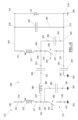
コンバータ145は、電気負荷110の両端に電気的に接続可能な第1の出力端子165および第2の出力端子170をさらに備えることができる。
電圧波を生成するために、波動発生器175は、少なくとも1つの能動スイッチ180、例えば、適切な電気駆動信号の指令を受けてオン/オフ(すなわち、遮断状態から飽和状態へ、またはその逆)することができるトランジスタ(例えば、バイポーラジャンクショントランジスタBJT、電界効果トランジスタFET、MOSFET、GaN、SiC、MESFET、JFET、IGBTなど)を備えている。
この場合、共振回路200は、能動スイッチ180に接続されており、オフからオンへの各スイッチングフェーズの間、好ましくはオンからオフへの各スイッチングフェーズの間にも、能動スイッチ180に印加される電圧および/または電力を低減するように調整されている。
一次回路は、第1の入力端子150から第1の中間電気ノード202まで延びる第1の電気分岐201と、当該中間電気ノード202から第2の入力端子155まで、または第2の入力端子155にも接続可能な所定の一次回路基準電圧204まで延びる第2の電気分岐203と、を備えている。
電力は、第1の共振キャパシタンス220と、場合によっては第2の共振キャパシタンス240(存在する場合)によって実現される容量性結合によって、一次回路から二次回路へと送ることができる。
逆に、能動スイッチ300がオンのとき、すなわち飽和状態のときには、第1の導電端子256と第2の導電端子257の間に電流が自由に流れる。
実際には、コントローラ600は、二次回路電圧、すなわち第1の端子256(例えばMOSFETドレイン上)の電気電圧が0Vを下回ったときに能動スイッチ300をオンにし、能動スイッチ180のオフに実質的に同期してオフにするように、あるいはどのような場合でも電流が略ゼロになったときにオフにするように、較正された駆動信号を生成して、負荷110に伝達される電力を最大化するように構成することができる。
実際、電流IDの発振期間がスイッチ180のターンオン期間の約数となるように第3の共振インダクタ280を選択すると、瞬間的なターンオフ電流を最小化することができ、その結果、回路をゼロ電流スイッチングに近い状態にするか、あるいはいずれにしても電流を強く減少させることができる。
Claims (12)
- 電気負荷に電力を供給するためのコンバータであって、
直流又は類似の電圧を直流電圧に印加可能な第1の入力端子及び第2の入力端子と、
前記電気負荷の両端に接続可能な第1の出力端子及び第2の出力端子と、
波動発生器と、
整流段と、
を備え、
前記波動発生器が、
前記第1の入力端子を第1の中間電気ノードに接続する第1の電気分岐と、
前記第1の中間電気ノードを前記第2の入力端子に接続する第2の電気分岐と、
前記第2の電気分岐に設置される第1の能動スイッチであって、前記第1の中間電気ノードに接続される第1の導電端子と、前記第2の入力端子に接続される第2の導電端子と、電気駆動信号を受信して、前記第1及び前記第2の導電端子間に電流が流れることを許容する飽和状態と電流が流れないようにする遮断状態の間で前記第1の能動スイッチを切り替える制御端子とを有する第1の能動スイッチと、
前記第1の能動スイッチが前記遮断状態から前記飽和状態に切り替わる少なくとも瞬間に、前記第1の能動スイッチに印加される電圧及び又は電流を低減させる共振回路と、
を備え、
前記整流段が、
前記第1の出力端子を第2の中間電気ノードに接続する第3の電気分岐と、
前記第2の中間電気ノードを前記第2の出力端子に接続する第4の電気分岐と、
該第4の電気分岐に位置するダイオード又は第2の能動スイッチと、
を備え、
前記ダイオードが、前記第2の中間電気ノードに接続されるカソードと、前記第2の出力端子に接続されるアノードと、を備え、
前記第2の能動スイッチが、前記第2の中間電気ノードに接続される第1の導電端子と、前記第2の出力端子に接続される第2の導電端子と、電気駆動信号を受信して、前記第1及び前記第2の導電端子間に電流が流れることを許容する飽和状態と電流が流れないようにする遮断状態の間で前記第2の能動スイッチを切り替える制御端子と、を有し、
該共振回路が、少なくとも、
前記第1の電気分岐に設置される第1の共振インダクタであって、前記第1の入力端子に接続される第1の端子と前記第1の中間電気ノードに接続される第2の端子とを有する第1の共振インダクタと、
前記第3の電気分岐に設置される第2の共振インダクタであって、前記第2の中間電気ノードに接続される第1の端子と前記第1の出力端子に接続される第2の端子とを有する第2の共振インダクタと、
前記第1の中間電気ノードに接続される第1の端子と、前記第2の中間電気ノードに接続される第2の端子と、を備える第1の共振キャパシタンスと、
を備え、
前記第1の共振インダクタ及び前記第2の共振インダクタが、1未満の相互結合係数で誘導結合され、
前記波動発生器が、前記第1の能動スイッチ以外のスイッチを備えないコンバータ。 - 前記第1の共振インダクタと前記第2の共振インダクタの間の前記結合係数が、0.1から0.8の間である請求項1に記載のコンバータ。
- 前記第1の共振インダクタと前記第2の共振インダクタの間の前記結合係数が、0.2から0.6の間である請求項2に記載のコンバータ。
- 前記第2の出力端子に接続される第1の端子と、前記第2の入力端子に接続される第2の端子と、を有する第2の共振キャパシタンスを備える請求項1から3のいずれか一項に記載のコンバータ。
- 前記第1の能動スイッチを周期的にオン/オフするように構成される第1のコントローラを備え、
該第1のコントローラが、前記第1の能動スイッチの前記第1の導電端子に印加される電圧を測定し、該測定された電圧がキャンセルされた場合に、前記第1の能動スイッチをオンにするように構成される請求項1から4のいずれか一項に記載のコンバータ。 - 前記第2の能動スイッチを周期的にオン/オフするように構成される第2のコントローラを備え、
該第2のコントローラが、前記第2の能動スイッチの前記第1の導電端子に印加される電圧を測定し、該測定された電圧がキャンセルされた場合に、前記第2の能動スイッチをオンにするように構成される請求項5に記載のコンバータ。 - 前記第2のコントローラが、期間の継続時間よりも短いターンオン時間の間、前記第2の能動スイッチをオン状態に維持し、前記第1のコントローラが前記第1の能動スイッチをオフにした時点で、又は一定の遅延を伴って、前記第2の能動スイッチをオフにするように構成される請求項6に記載のコンバータ。
- 前記第2のコントローラが、前記第1の出力端子に印加される電圧の値を測定し、前記電圧の測定値と目標値との差を最小化するように、前記第2の能動スイッチをオフにする際の遅延を変更するように構成される請求項7に記載のコンバータ。
- 前記第1のコントローラが、前記第1の能動スイッチの前記第1の導電端子に印加される電圧のピーク値を測定し、該電圧のピークの測定値と目標値との差を最小化するように、前記第1の能動スイッチのターンオン時間を変更する請求項6または7に記載のコンバータ。
- 前記第1の中間電気ノードを、前記第1の共振キャパシタンスの前記第1の端子に接続する電気分岐に沿って配置される第3の共振インダクタを備える請求項1から9のいずれか一項に記載のコンバータ。
- 前記ダイオードまたは前記第2の能動スイッチに並列に接続されるタンクキャパシタンスを備える請求項1から10のいずれか一項に記載のコンバータ。
- 前記第1の能動スイッチに並列に接続されるタンクキャパシタンスを備える請求項1から11のいずれか一項に記載のコンバータ。
Applications Claiming Priority (3)
| Application Number | Priority Date | Filing Date | Title |
|---|---|---|---|
| IT102019000007974A IT201900007974A1 (it) | 2019-06-04 | 2019-06-04 | Convertitore per trasferire potenza elettrica ad un carico elettrico |
| IT102019000007974 | 2019-06-04 | ||
| PCT/IB2020/054934 WO2020245699A1 (en) | 2019-06-04 | 2020-05-25 | Converter for transferring electric power to an electrical load |
Publications (2)
| Publication Number | Publication Date |
|---|---|
| JP2022535537A JP2022535537A (ja) | 2022-08-09 |
| JP7542013B2 true JP7542013B2 (ja) | 2024-08-29 |
Family
ID=67957343
Family Applications (1)
| Application Number | Title | Priority Date | Filing Date |
|---|---|---|---|
| JP2021571739A Active JP7542013B2 (ja) | 2019-06-04 | 2020-05-25 | 電気負荷に電力を供給するためのコンバータ |
Country Status (8)
| Country | Link |
|---|---|
| US (1) | US11967902B2 (ja) |
| EP (1) | EP3981064B1 (ja) |
| JP (1) | JP7542013B2 (ja) |
| KR (1) | KR102643411B1 (ja) |
| CN (1) | CN114144968B (ja) |
| IT (1) | IT201900007974A1 (ja) |
| TW (1) | TWI871320B (ja) |
| WO (1) | WO2020245699A1 (ja) |
Families Citing this family (3)
| Publication number | Priority date | Publication date | Assignee | Title |
|---|---|---|---|---|
| TWI921774B (zh) * | 2024-04-02 | 2026-04-11 | 致茂電子股份有限公司 | 電子負載裝置及其操作方法 |
| US12683481B2 (en) | 2024-04-24 | 2026-07-14 | Alpha And Omega Semiconductor International Lp | Zero voltage switching hybrid converter |
| CN118916589B (zh) * | 2024-07-17 | 2025-09-30 | 武汉大学 | 一种适用于形状任意的空心耦合线圈的频响特性计算方法 |
Citations (4)
| Publication number | Priority date | Publication date | Assignee | Title |
|---|---|---|---|---|
| JP2003204679A (ja) | 2002-01-08 | 2003-07-18 | Japan Science & Technology Corp | ドライバー回路、dc−dcコンバータ及び整流器 |
| US20120013313A1 (en) | 2010-07-19 | 2012-01-19 | Intersil Americas Inc. | Multiphase dc-dc converter using zero voltage switching |
| WO2013058175A1 (ja) | 2011-10-21 | 2013-04-25 | 株式会社村田製作所 | スイッチング電源装置 |
| JP2017505596A (ja) | 2014-01-22 | 2017-02-16 | デンマークス テクニスク ユニヴェルジテイト | 共振降圧dc−dc電力コンバータ |
Family Cites Families (15)
| Publication number | Priority date | Publication date | Assignee | Title |
|---|---|---|---|---|
| JPS5378042A (en) * | 1976-12-20 | 1978-07-11 | Sanyo Electric Co Ltd | Switching control type power source circuit |
| US20020030451A1 (en) * | 2000-02-25 | 2002-03-14 | Moisin Mihail S. | Ballast circuit having voltage clamping circuit |
| US6462962B1 (en) * | 2000-09-08 | 2002-10-08 | Slobodan Cuk | Lossless switching DC-to-DC converter |
| US7286373B1 (en) * | 2006-04-07 | 2007-10-23 | Li Shin International Enterprise Corporation | Full-resonant power circuit device for receiving a variable input voltage |
| WO2012101905A1 (ja) * | 2011-01-26 | 2012-08-02 | 株式会社村田製作所 | スイッチング電源装置 |
| US9231471B2 (en) * | 2011-03-28 | 2016-01-05 | Cuks, Llc | Hybrid-switching step-down converter with a hybrid transformer |
| CN103199697B (zh) * | 2012-01-10 | 2016-07-06 | 台达电子企业管理(上海)有限公司 | 直流对直流转换器及其控制方法 |
| ITRE20120021A1 (it) | 2012-04-02 | 2013-10-03 | Igor Spinella | Metodo ed apparato per il trasferimento di potenza elettrica |
| WO2016161280A1 (en) * | 2015-04-01 | 2016-10-06 | The Regents Of The University Of Michigan | Double-sided lclc-compensated topology for capacitive power transfer |
| US9893631B2 (en) * | 2015-09-23 | 2018-02-13 | Toyota Motor Engineering & Manufacturing North America, Inc. | Non-isolated DC-DC conversion circuit configured for capacitive and magnetic power transfer |
| US10298132B2 (en) * | 2016-10-13 | 2019-05-21 | Intersil Americas LLC | Switching power supply for low step down conversion ratio with reduced switching losses |
| CN106849372B (zh) * | 2017-03-11 | 2019-03-22 | 重庆大学 | 基于双侧f-lclc谐振网络的ecpt系统及其参数设计方法 |
| TWI840390B (zh) | 2018-09-26 | 2024-05-01 | 義大利商埃格特羅尼克工程股份公司 | 用於傳送電力至電力負載之系統 |
| CN109450256B (zh) * | 2018-12-03 | 2020-12-01 | 昂宝电子(上海)有限公司 | 一种准谐振电源控制器 |
| US10804798B1 (en) * | 2019-04-29 | 2020-10-13 | Infineon Technologies Austria Ag | Switched-capacitor converter with multi-tapped autotransformer |
-
2019
- 2019-06-04 IT IT102019000007974A patent/IT201900007974A1/it unknown
-
2020
- 2020-05-13 TW TW109115913A patent/TWI871320B/zh active
- 2020-05-25 CN CN202080052725.9A patent/CN114144968B/zh active Active
- 2020-05-25 EP EP20727862.3A patent/EP3981064B1/en active Active
- 2020-05-25 WO PCT/IB2020/054934 patent/WO2020245699A1/en not_active Ceased
- 2020-05-25 KR KR1020217039466A patent/KR102643411B1/ko active Active
- 2020-05-25 JP JP2021571739A patent/JP7542013B2/ja active Active
- 2020-05-25 US US17/615,681 patent/US11967902B2/en active Active
Patent Citations (4)
| Publication number | Priority date | Publication date | Assignee | Title |
|---|---|---|---|---|
| JP2003204679A (ja) | 2002-01-08 | 2003-07-18 | Japan Science & Technology Corp | ドライバー回路、dc−dcコンバータ及び整流器 |
| US20120013313A1 (en) | 2010-07-19 | 2012-01-19 | Intersil Americas Inc. | Multiphase dc-dc converter using zero voltage switching |
| WO2013058175A1 (ja) | 2011-10-21 | 2013-04-25 | 株式会社村田製作所 | スイッチング電源装置 |
| JP2017505596A (ja) | 2014-01-22 | 2017-02-16 | デンマークス テクニスク ユニヴェルジテイト | 共振降圧dc−dc電力コンバータ |
Also Published As
| Publication number | Publication date |
|---|---|
| US20220255430A1 (en) | 2022-08-11 |
| EP3981064B1 (en) | 2024-03-13 |
| JP2022535537A (ja) | 2022-08-09 |
| EP3981064A1 (en) | 2022-04-13 |
| EP3981064C0 (en) | 2024-03-13 |
| KR102643411B1 (ko) | 2024-03-05 |
| CN114144968B (zh) | 2025-05-16 |
| WO2020245699A1 (en) | 2020-12-10 |
| IT201900007974A1 (it) | 2020-12-04 |
| CN114144968A (zh) | 2022-03-04 |
| KR20220016850A (ko) | 2022-02-10 |
| TWI871320B (zh) | 2025-02-01 |
| TW202101889A (zh) | 2021-01-01 |
| US11967902B2 (en) | 2024-04-23 |
Similar Documents
| Publication | Publication Date | Title |
|---|---|---|
| US11011936B2 (en) | Single-stage transmitter for wireless power transfer | |
| CN103329398B (zh) | 电力输送系统 | |
| US9048741B2 (en) | Switching power supply device | |
| KR102009351B1 (ko) | 2개의 변압기 구조를 사용해 균형있는 2차측 전류를 갖는 고효율 llc 공진 컨버터 | |
| US7388760B2 (en) | Switching power supply circuit | |
| US20140334193A1 (en) | Self-oscillating loop based piezoelectric power converter | |
| US20140247625A1 (en) | Switching power supply device | |
| KR20130114693A (ko) | 스위칭 전원장치 | |
| US11011937B2 (en) | High frequency power supply device | |
| KR20230038744A (ko) | 변환기의 성능 향상 | |
| TWI871320B (zh) | 傳輸電功率至電負載之轉換器 | |
| JP2021035077A (ja) | 無線給電装置 | |
| Wei et al. | Control strategies overview for LLC resonant converter with fixed frequency operation | |
| US11569757B2 (en) | System for transferring electrical power to an electrical load | |
| US11355962B2 (en) | Apparatus for transferring electrical power to an electrical load with converter | |
| Colak et al. | A novel common mode multi-phase half-wave semi-synchronous rectifier for inductive power transfer applications | |
| CN102630368A (zh) | 具有功率因数校正的通量转换器 | |
| Kulasekaran et al. | A 500 kHz, 3.3 kW boost PFC with low loss coupled auxiliary ZVT circuit | |
| RU205720U1 (ru) | Резонансный конвертор напряжения | |
| IT202100002360A1 (it) | Convertitore per trasferire potenza elettrica ad un carico elettrico | |
| Jang et al. | A new soft-switched contactless battery charger with robust local controllers | |
| Salich et al. | Investigation of the zero-current switched class E converters for automotive wireless power transfer inductive charging applications | |
| JP2005057923A (ja) | スイッチング電源回路 | |
| JP2005057924A (ja) | スイッチング電源回路 |
Legal Events
| Date | Code | Title | Description |
|---|---|---|---|
| A529 | Written submission of copy of amendment under article 34 pct |
Free format text: JAPANESE INTERMEDIATE CODE: A529 Effective date: 20211202 |
|
| A621 | Written request for application examination |
Free format text: JAPANESE INTERMEDIATE CODE: A621 Effective date: 20230303 |
|
| A131 | Notification of reasons for refusal |
Free format text: JAPANESE INTERMEDIATE CODE: A131 Effective date: 20240130 |
|
| A977 | Report on retrieval |
Free format text: JAPANESE INTERMEDIATE CODE: A971007 Effective date: 20240131 |
|
| A521 | Request for written amendment filed |
Free format text: JAPANESE INTERMEDIATE CODE: A523 Effective date: 20240425 |
|
| TRDD | Decision of grant or rejection written | ||
| A01 | Written decision to grant a patent or to grant a registration (utility model) |
Free format text: JAPANESE INTERMEDIATE CODE: A01 Effective date: 20240730 |
|
| A61 | First payment of annual fees (during grant procedure) |
Free format text: JAPANESE INTERMEDIATE CODE: A61 Effective date: 20240819 |
|
| R150 | Certificate of patent or registration of utility model |
Ref document number: 7542013 Country of ref document: JP Free format text: JAPANESE INTERMEDIATE CODE: R150 |