JP7550003B2 - Vehicle lighting fixture and lamp control module - Google Patents
Vehicle lighting fixture and lamp control module Download PDFInfo
- Publication number
- JP7550003B2 JP7550003B2 JP2020155749A JP2020155749A JP7550003B2 JP 7550003 B2 JP7550003 B2 JP 7550003B2 JP 2020155749 A JP2020155749 A JP 2020155749A JP 2020155749 A JP2020155749 A JP 2020155749A JP 7550003 B2 JP7550003 B2 JP 7550003B2
- Authority
- JP
- Japan
- Prior art keywords
- light
- emitting elements
- lighting
- channel
- lamp
- Prior art date
- Legal status (The legal status is an assumption and is not a legal conclusion. Google has not performed a legal analysis and makes no representation as to the accuracy of the status listed.)
- Active
Links
- 230000004044 response Effects 0.000 claims description 3
- 238000010586 diagram Methods 0.000 description 22
- 230000008859 change Effects 0.000 description 6
- 230000006870 function Effects 0.000 description 6
- 238000000034 method Methods 0.000 description 5
- 238000012986 modification Methods 0.000 description 4
- 230000004048 modification Effects 0.000 description 4
- 101000685663 Homo sapiens Sodium/nucleoside cotransporter 1 Proteins 0.000 description 3
- 102100023116 Sodium/nucleoside cotransporter 1 Human genes 0.000 description 3
- 230000004397 blinking Effects 0.000 description 3
- 230000008569 process Effects 0.000 description 3
- 230000007704 transition Effects 0.000 description 3
- 230000000694 effects Effects 0.000 description 2
- 238000005401 electroluminescence Methods 0.000 description 2
- 239000004065 semiconductor Substances 0.000 description 2
- 230000000295 complement effect Effects 0.000 description 1
- 230000014509 gene expression Effects 0.000 description 1
- 230000001105 regulatory effect Effects 0.000 description 1
- 238000006467 substitution reaction Methods 0.000 description 1
Images




Classifications
-
- B—PERFORMING OPERATIONS; TRANSPORTING
- B60—VEHICLES IN GENERAL
- B60Q—ARRANGEMENT OF SIGNALLING OR LIGHTING DEVICES, THE MOUNTING OR SUPPORTING THEREOF OR CIRCUITS THEREFOR, FOR VEHICLES IN GENERAL
- B60Q1/00—Arrangement of optical signalling or lighting devices, the mounting or supporting thereof or circuits therefor
- B60Q1/26—Arrangement of optical signalling or lighting devices, the mounting or supporting thereof or circuits therefor the devices being primarily intended to indicate the vehicle, or parts thereof, or to give signals, to other traffic
- B60Q1/34—Arrangement of optical signalling or lighting devices, the mounting or supporting thereof or circuits therefor the devices being primarily intended to indicate the vehicle, or parts thereof, or to give signals, to other traffic for indicating change of drive direction
- B60Q1/343—Manually actuated switching arrangements therefor
-
- H—ELECTRICITY
- H05—ELECTRIC TECHNIQUES NOT OTHERWISE PROVIDED FOR
- H05B—ELECTRIC HEATING; ELECTRIC LIGHT SOURCES NOT OTHERWISE PROVIDED FOR; CIRCUIT ARRANGEMENTS FOR ELECTRIC LIGHT SOURCES, IN GENERAL
- H05B45/00—Circuit arrangements for operating light-emitting diodes [LED]
- H05B45/10—Controlling the intensity of the light
-
- H—ELECTRICITY
- H05—ELECTRIC TECHNIQUES NOT OTHERWISE PROVIDED FOR
- H05B—ELECTRIC HEATING; ELECTRIC LIGHT SOURCES NOT OTHERWISE PROVIDED FOR; CIRCUIT ARRANGEMENTS FOR ELECTRIC LIGHT SOURCES, IN GENERAL
- H05B45/00—Circuit arrangements for operating light-emitting diodes [LED]
- H05B45/30—Driver circuits
- H05B45/345—Current stabilisation; Maintaining constant current
-
- H—ELECTRICITY
- H05—ELECTRIC TECHNIQUES NOT OTHERWISE PROVIDED FOR
- H05B—ELECTRIC HEATING; ELECTRIC LIGHT SOURCES NOT OTHERWISE PROVIDED FOR; CIRCUIT ARRANGEMENTS FOR ELECTRIC LIGHT SOURCES, IN GENERAL
- H05B45/00—Circuit arrangements for operating light-emitting diodes [LED]
- H05B45/30—Driver circuits
- H05B45/37—Converter circuits
- H05B45/3725—Switched mode power supply [SMPS]
- H05B45/375—Switched mode power supply [SMPS] using buck topology
-
- H—ELECTRICITY
- H05—ELECTRIC TECHNIQUES NOT OTHERWISE PROVIDED FOR
- H05B—ELECTRIC HEATING; ELECTRIC LIGHT SOURCES NOT OTHERWISE PROVIDED FOR; CIRCUIT ARRANGEMENTS FOR ELECTRIC LIGHT SOURCES, IN GENERAL
- H05B45/00—Circuit arrangements for operating light-emitting diodes [LED]
- H05B45/40—Details of LED load circuits
- H05B45/44—Details of LED load circuits with an active control inside an LED matrix
- H05B45/48—Details of LED load circuits with an active control inside an LED matrix having LEDs organised in strings and incorporating parallel shunting devices
-
- B—PERFORMING OPERATIONS; TRANSPORTING
- B60—VEHICLES IN GENERAL
- B60Q—ARRANGEMENT OF SIGNALLING OR LIGHTING DEVICES, THE MOUNTING OR SUPPORTING THEREOF OR CIRCUITS THEREFOR, FOR VEHICLES IN GENERAL
- B60Q1/00—Arrangement of optical signalling or lighting devices, the mounting or supporting thereof or circuits therefor
- B60Q1/26—Arrangement of optical signalling or lighting devices, the mounting or supporting thereof or circuits therefor the devices being primarily intended to indicate the vehicle, or parts thereof, or to give signals, to other traffic
- B60Q1/34—Arrangement of optical signalling or lighting devices, the mounting or supporting thereof or circuits therefor the devices being primarily intended to indicate the vehicle, or parts thereof, or to give signals, to other traffic for indicating change of drive direction
- B60Q1/38—Arrangement of optical signalling or lighting devices, the mounting or supporting thereof or circuits therefor the devices being primarily intended to indicate the vehicle, or parts thereof, or to give signals, to other traffic for indicating change of drive direction using immovably-mounted light sources, e.g. fixed flashing lamps
- B60Q1/381—Arrangement of optical signalling or lighting devices, the mounting or supporting thereof or circuits therefor the devices being primarily intended to indicate the vehicle, or parts thereof, or to give signals, to other traffic for indicating change of drive direction using immovably-mounted light sources, e.g. fixed flashing lamps with several light sources activated in sequence, e.g. to create a sweep effect
Landscapes
- Engineering & Computer Science (AREA)
- Mechanical Engineering (AREA)
- Lighting Device Outwards From Vehicle And Optical Signal (AREA)
- Circuit Arrangement For Electric Light Sources In General (AREA)
- Control Of Indicators Other Than Cathode Ray Tubes (AREA)
Description
本開示は、自動車などの車両に用いられる灯具に関する。 This disclosure relates to lighting fixtures for use in vehicles such as automobiles.
近年、車両用灯具の高機能化が進められており、ヘッドランプには、ロービーム、ハイビーム、ターンシグナルランプ、ポジションランプ、デイタイムランニングランプなど、役割が異なる複数のランプが設けられ、車両からの制御信号に応じて、複数のランプの光源を適切な輝度で発光させる必要がある。 In recent years, vehicle lighting has become more and more sophisticated, and headlamps are now equipped with multiple lamps with different functions, such as low beam, high beam, turn signal lamp, position lamp, and daytime running lamp, and it is necessary to control the light sources of these multiple lamps to emit light at an appropriate brightness in response to control signals from the vehicle.
近年、いくつかの車両に、一方向に流れるように順に点灯していくターンシグナルランプ(以下、シーケンシャルターンランプという)が搭載されはじめている。ターンシグナルランプの点灯パターンの仕様は、車両ごとに規定されるため、ランプメーカは、要求仕様に応じて、ランプの制御システムを設計する必要があった。 In recent years, some vehicles have begun to be equipped with turn signal lamps that light up in a sequential manner in one direction (hereafter referred to as sequential turn lamps). Because the specifications for the lighting pattern of turn signal lamps are regulated for each vehicle, lamp manufacturers have had to design lamp control systems according to the required specifications.
本開示はかかる状況においてなされたものであり、そのある態様の例示的な目的のひとつは、ターンシグナルランプのさまざまな点灯パターンに対応可能な車両用灯具の提供にある。 This disclosure has been made in light of such circumstances, and one exemplary purpose of one embodiment thereof is to provide a vehicle lamp that can accommodate various lighting patterns of turn signal lamps.
本開示のある態様は、車両用灯具に関する。車両用灯具は、独立に点消灯が制御可能な複数の発光素子を含むターンランプと、複数の発光素子の制御に関するパラメータを格納する不揮発性メモリと、ソフトウェアプログラムを実行することにより、パラメータにもとづいて、各時刻における複数の発光素子の点灯状態を指示する複数の点灯指令を生成する信号処理装置と、複数の点灯指令にもとづいて、複数の発光素子それぞれを駆動する駆動回路と、を備える。 One aspect of the present disclosure relates to a vehicle lamp. The vehicle lamp includes a turn signal lamp including a plurality of light-emitting elements that can be independently controlled to be turned on and off, a non-volatile memory that stores parameters related to the control of the plurality of light-emitting elements, a signal processing device that executes a software program to generate a plurality of lighting commands that indicate the lighting state of the plurality of light-emitting elements at each time based on the parameters, and a drive circuit that drives each of the plurality of light-emitting elements based on the plurality of lighting commands.
本開示の別の態様は、独立に点消灯が制御可能な複数の発光素子を含むターンランプを備える車両用灯具に使用されるランプコントロールモジュールに関する。ランプコントロールモジュールは、複数の発光素子の制御に関するパラメータを格納する不揮発性メモリと、ソフトウェアプログラムを実行することにより、パラメータにもとづいて、各時刻における複数の発光素子の点灯状態を指示する複数の点灯指令を生成する信号処理装置と、複数の点灯指令にもとづいて、複数の発光素子それぞれを駆動する駆動回路と、を備える。 Another aspect of the present disclosure relates to a lamp control module used in a vehicle lamp equipped with a turn signal lamp including a plurality of light-emitting elements that can be independently controlled to be turned on and off. The lamp control module includes a non-volatile memory that stores parameters related to the control of the plurality of light-emitting elements, a signal processing device that executes a software program to generate a plurality of lighting commands that indicate the lighting state of the plurality of light-emitting elements at each time based on the parameters, and a drive circuit that drives each of the plurality of light-emitting elements based on the plurality of lighting commands.
なお、以上の構成要素の任意の組み合わせや本発明の構成要素や表現を、方法、装置、システムなどの間で相互に置換したものもまた、本発明の態様として有効である。 In addition, any combination of the above components or mutual substitution of the components or expressions of the present invention between methods, devices, systems, etc. are also valid aspects of the present invention.
本開示のある態様によれば、ハードウェア/ソフトウェアプログラムを変更せずに、ターンシグナルランプをさまざまな態様で点滅させることができる。 According to certain aspects of the present disclosure, turn signal lamps can be made to flash in various ways without modifying the hardware/software programs.
(実施形態の概要)
本開示のいくつかの例示的な実施形態の概要を説明する。この概要は、後述する詳細な説明の前置きとして、実施形態の基本的な理解を目的として、1つまたは複数の実施形態のいくつかの概念を簡略化して説明するものであり、発明あるいは開示の広さを限定するものではない。またこの概要は、考えられるすべての実施形態の包括的な概要ではなく、実施形態の欠くべからざる構成要素を限定するものではない。便宜上、「一実施形態」は、本明細書に開示するひとつの実施形態または複数の実施形態を指すものとして用いる場合がある。
(Overview of the embodiment)
A summary of some exemplary embodiments of the present disclosure will be described. This summary is intended to provide a simplified overview of some concepts of one or more embodiments in order to provide a basic understanding of the embodiments as a prelude to the detailed description that follows, and is not intended to limit the scope of the invention or disclosure. Additionally, this summary is not an exhaustive overview of all possible embodiments, nor does it limit essential components of the embodiments. For convenience, the term "one embodiment" may be used to refer to one embodiment or multiple embodiments disclosed herein.
一実施形態に係る車両用灯具は、独立に点消灯が制御可能な複数の発光素子を含むターンランプと、ランプコントロールモジュールを備える。ランプコントロールモジュールは、複数の発光素子の制御に関するパラメータを格納する不揮発性メモリと、ソフトウェアプログラムを実行することにより、パラメータにもとづいて、各時刻における複数の発光素子の点灯状態を指示する複数の点灯指令を生成する信号処理装置と、複数の点灯指令にもとづいて、複数の発光素子それぞれを駆動する駆動回路と、を備える。 A vehicle lamp according to one embodiment includes a turn signal lamp including a plurality of light-emitting elements that can be independently controlled to be turned on and off, and a lamp control module. The lamp control module includes a non-volatile memory that stores parameters related to the control of the plurality of light-emitting elements, a signal processing device that executes a software program to generate a plurality of lighting commands that indicate the lighting state of the plurality of light-emitting elements at each time based on the parameters, and a drive circuit that drives each of the plurality of light-emitting elements based on the plurality of lighting commands.
この構成によれば、ソフトウェアプログラムおよびハードウェアを大きく変更することなく、不揮発性メモリのパラメータに応じて、さまざまな点灯パターンを実現できる。 With this configuration, various lighting patterns can be achieved according to the parameters of the non-volatile memory without making major changes to the software program and hardware.
一実施形態において、パラメータは、複数の発光素子それぞれの点灯タイミングを、基準時刻からの経過時間として規定する複数の第1データを含んでもよい。これにより、複数の発光素子の点灯順序と点灯する時間差を任意に設定できるようになる。 In one embodiment, the parameters may include a plurality of first data that define the lighting timing of each of the plurality of light-emitting elements as the elapsed time from a reference time. This makes it possible to arbitrarily set the lighting sequence and lighting time difference of the plurality of light-emitting elements.
一実施形態において、パラメータは、複数の発光素子の輝度が0から目標値に達するまでの調光時間を規定する第2データをさらに含んでもよい。信号処理装置は、各時刻における複数の発光素子の輝度を指示する複数の点灯指令を生成してもよい。これにより、各発光素子を徐々に点灯させたり、短時間で点灯させるなどの制御が可能となる。 In one embodiment, the parameters may further include second data that specifies a dimming time for the luminance of the multiple light-emitting elements to reach a target value from 0. The signal processing device may generate multiple lighting commands that indicate the luminance of the multiple light-emitting elements at each time. This makes it possible to control the lighting of each light-emitting element, such as gradually lighting it or lighting it for a short period of time.
一実施形態において、駆動回路は、Nチャンネル(N≧2)の出力を有してもよい。パラメータは、複数の発光素子の個数m(≦N)を規定する第3データを含んでもよい。これにより、Nチャンネルのうち、mチャンネルを使用し、残りを不使用チャンネルに設定できるようになり、ランプコントロールモジュールを、発光素子の個数が異なる車両用灯具で汎用的に使用できるようになる。 In one embodiment, the drive circuit may have an output of N channels (N≧2). The parameters may include third data that specifies the number m (≦N) of the multiple light-emitting elements. This makes it possible to use m of the N channels and set the remaining channels as unused channels, making it possible to universally use the lamp control module with vehicle lamps having different numbers of light-emitting elements.
一実施形態において、駆動回路は、Nチャンネル(N≧2)の出力を有してもよい。ランプコントロールモジュールは、第1チャンネルから第Nチャンネルに向かって順に点灯する第1モードと、第Nチャンネルから第1チャンネルに向かって順に点灯する第2モードと、が切りかえ可能であってもよい。パラメータは、第1モードと第2モードを指定する第4データをさらに含んでもよい。 In one embodiment, the drive circuit may have an output of N channels (N≧2). The lamp control module may be switchable between a first mode in which the first channel is turned on in sequence to the Nth channel, and a second mode in which the Nth channel is turned on in sequence to the first channel. The parameters may further include fourth data that specifies the first mode and the second mode.
一実施形態において、複数の発光素子は直列に接続されてもよい。駆動回路は、複数の発光素子の直列接続回路に駆動電流を供給する定電流回路と、複数の発光素子と並列に接続される複数のバイパススイッチと、複数の点灯指令に応じて複数のバイパススイッチを駆動するコントローラと、を含んでもよい。 In one embodiment, the multiple light-emitting elements may be connected in series. The drive circuit may include a constant current circuit that supplies a drive current to the series-connected circuit of the multiple light-emitting elements, multiple bypass switches that are connected in parallel to the multiple light-emitting elements, and a controller that drives the multiple bypass switches in response to multiple lighting commands.
(実施形態)
以下、本発明を好適な実施の形態をもとに図面を参照しながら説明する。各図面に示される同一または同等の構成要素、部材、処理には、同一の符号を付するものとし、適宜重複した説明は省略する。また、実施の形態は、発明を限定するものではなく例示であって、実施の形態に記述されるすべての特徴やその組み合わせは、必ずしも発明の本質的なものであるとは限らない。
(Embodiment)
The present invention will be described below based on preferred embodiments with reference to the drawings. The same or equivalent components, parts, and processes shown in each drawing are given the same reference numerals, and duplicated descriptions are omitted as appropriate. In addition, the embodiments are illustrative rather than limiting the invention, and all features and combinations thereof described in the embodiments are not necessarily essential to the invention.
本明細書において、「部材Aが、部材Bと接続された状態」とは、部材Aと部材Bが物理的に直接的に接続される場合のほか、部材Aと部材Bが、それらの電気的な接続状態に実質的な影響を及ぼさない、あるいはそれらの結合により奏される機能や効果を損なわせない、その他の部材を介して間接的に接続される場合も含む。 In this specification, "a state in which component A is connected to component B" includes not only cases in which component A and component B are directly physically connected, but also cases in which component A and component B are indirectly connected via other components that do not substantially affect their electrical connection state or impair the function or effect achieved by their combination.
同様に、「部材Cが、部材Aと部材Bの間に設けられた状態」とは、部材Aと部材C、あるいは部材Bと部材Cが直接的に接続される場合のほか、それらの電気的な接続状態に実質的な影響を及ぼさない、あるいはそれらの結合により奏される機能や効果を損なわせない、その他の部材を介して間接的に接続される場合も含む。 Similarly, "a state in which component C is provided between components A and B" includes not only cases in which components A and C, or components B and C, are directly connected, but also cases in which they are indirectly connected via other components that do not substantially affect their electrical connection state or impair the function or effect achieved by their combination.
図1は、実施形態に係る灯具システム100のブロック図である。灯具システム100は、車両110と、車両用灯具(ヘッドランプ)200とを備える。車両110には、車両側のECU(Electronic Control Unit)やバッテリ、各ランプのスイッチなどが含まれる。
Figure 1 is a block diagram of a
車両用灯具200は、ロービーム(Lo)、ハイビーム(Hi)、デイタイムランニングランプ(DRL)、ポジションランプ(POS)、ターンシグナルランプ(TURN)などの機能を備える。図1には、そのうち、ターンシグナルランプTURNに関連する構成のみを示す。
The
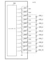
車両用灯具200は、複数の発光素子203_1~203_N(N≧2)およびランプコントロールモジュール300を備える。ターンシグナルランプ用の光源202は、複数の発光素子203_1~203_Nを含む。
The
発光素子203_1~203_Nは、LED(発光ダイオード)あるいはLD(レーザダイオード)などの半導体発光素子である。 Light-emitting elements 203_1 to 203_N are semiconductor light-emitting elements such as LEDs (light-emitting diodes) or LDs (laser diodes).
半導体発光素子としては、白色LED(発光ダイオード)や、レーザダイオード、有機EL(Electro Luminescence)素子などが例示される。発光素子203の個数Nは、ターンシグナルランプ用光源202に要求される明るさや意匠を考慮して定めればよく、特に限定されない。
Examples of the semiconductor light-emitting element include a white LED (light-emitting diode), a laser diode, an organic EL (Electro Luminescence) element, etc. The number N of the light-
車両用灯具200には、車両110から電源ライン102を介して電源電圧+Bが供給される。
The
また車両用灯具200には、車両110からジカ線104を介してターンシグナルランプ201の点灯指令であるターン同期信号TURN_SYNCが入力される。ターン同期信号TURN_SYNCは、ターンシグナルランプ201の点滅を指示する信号であり、ターンシグナルランプ201の点滅時には、ハイレベルとローレベルを所定の周期で交互に繰り返すパルス信号となり、ハイ区間が点灯、ロー区間が消灯に対応付けられる。ターンシグナルランプ201の非点滅状態(消灯状態)において、ターン同期信号TURN_SYNCはローに固定される。
The
ランプコントロールモジュール300は、不揮発性メモリ308、入力インタフェース回路310、駆動回路330、信号処理装置400を備える。ランプコントロールモジュール300の主要な構成部品は、ひとつの筐体内に収容され、モジュール化されている。
The
入力インタフェース回路310は、ターン同期信号TURN_SYNCを受信する。たとえば入力インタフェース回路310は、単なるバッファで構成してもよい。
The
信号処理装置400は、ソフトウェアプログラムを実行可能なプロセッサを含む。信号処理装置400は、マイクロコントローラやCPU(Central Processing Unit)、DSP(Digital Signal Processor)などで構成することができる。
The
不揮発性メモリ308は、ターンシグナルランプ201を構成する複数の発光素子203_1~203_Nの制御に関するパラメータPARAMを格納する。
The
信号処理装置400は、ソフトウェアプログラムを実行することにより、パラメータPARAMにもとづいて、各時刻(制御周期)における複数の発光素子203_1~203_Nの点灯状態を指示する複数の点灯指令S1~SNを生成し、駆動回路330に供給する。
The
駆動回路330は、複数の点灯指令S1~SNにもとづいて、複数の発光素子203_1~203_Nを駆動する。i番目の点灯指令Siは、各時刻における発光素子203_iのオン、オフを示す。i番目の点灯指令Siは、各時刻における発光素子203_iのオン状態における輝度を示してもよい。
The
パラメータについて説明する。パラメータPARAMは、複数の発光素子203_1~203_Nそれぞれの点灯タイミングを、基準時刻tREFからの経過時間τ1~τNとして規定する複数の第1データD1_1~D1_Nを含む。基準時刻tREFは、ターン同期信号TURN_SYNCのポジティブエッジの時刻と一致していてもよいし、ポジティブエッジから所定時間経過後であってもよい。 The parameters will be described. The parameter PARAM includes a plurality of first data D1_1 to D1_N that specifies the lighting timing of each of the plurality of light-emitting elements 203_1 to 203_N as elapsed times τ 1 to τ N from a reference time t REF . The reference time t REF may coincide with the time of a positive edge of the turn synchronization signal TURN_SYNC, or may be a predetermined time after the positive edge.
i<jに対して、τi≦τjなる関係を制約条件として課してもよい。これにより点灯指令S1~SNが変化する順序が入れ替わることはないため、信号処理装置400が実行するソフトウェアプログラムを簡素化できる。
A constraint condition may be imposed such that τ i ≦τ j for i<j. This prevents the order in which the lighting commands S 1 to S N change from being changed, thereby simplifying the software program executed by the
さらにパラメータPARAMは、複数の発光素子203_1~203_Nの輝度が、0から目標値に達するまでの調光時間τ0を規定する第2データD2をさらに含むことができる。この場合、複数の点灯指令S1~SNは、各時刻における複数の発光素子203_1~203_Nの輝度を示す。以下では、消灯時の輝度を0%、点灯時の輝度を100%として説明する。 Furthermore, the parameter PARAM may further include second data D2 that specifies a dimming time τ 0 required for the luminance of the plurality of light-emitting elements 203_1 to 203_N to reach a target value from 0. In this case, the plurality of lighting commands S 1 to S N indicate the luminance of the plurality of light-emitting elements 203_1 to 203_N at each time. In the following description, the luminance when turned off is 0% and the luminance when turned on is 100%.
以上が灯具システム100の構成である。続いて灯具システム100の動作を説明する。
The above is the configuration of the
図2は、ターンシグナルランプの点滅を説明する図である。ターン同期信号TURN_SYNCは、所定の周期でハイとローを交互に繰り返す。 Figure 2 is a diagram explaining the blinking of the turn signal lamp. The turn synchronization signal TURN_SYNC alternates between high and low at a predetermined cycle.
ターン同期信号TURN_SYNCがハイに遷移すると、車両用灯具200は、パラメータPARAMに応じて、複数の点灯指令S1~SNを生成し、発光素子203_1~203_Nを点灯させる。この例では、複数の発光素子203_1~203_Nが順に点灯する様子が示される。
When the turn synchronization signal TURN_SYNC transitions to high, the
続いてターン同期信号TURN_SYNCがローに遷移すると、車両用灯具200は、複数の点灯指令S1~SNを一斉に、オフ状態に切りかえ、発光素子203_1~203_Nを消灯させる。
Subsequently, when the turn synchronization signal TURN_SYNC transitions to low, the
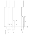
図3は、パラメータPARAMを説明する図である。たとえば経過時間τ1~τNは、0~200msの範囲で、5msステップで指定可能である。この5msを制御周期と称する。また調光時間τ0は0~20msの間で、Δt=5msステップで指定可能である。基準時刻tREFは、ターン同期信号TURN_SYNCのポジティブエッジのタイミングと一致してもよい。 3 is a diagram for explaining the parameter PARAM. For example, the elapsed times τ 1 to τ N can be specified in the range of 0 to 200 ms in 5 ms steps. This 5 ms is called a control period. The dimming time τ 0 can be specified in the range of 0 to 20 ms in Δt=5 ms steps. The reference time t REF may coincide with the timing of the positive edge of the turn synchronization signal TURN_SYNC.
この例では、点灯指令S1~SNは、輝度を表している。i番目の点灯指令Siは、基準時刻tREFから、第1データD1_iが示す時間τiの経過後までの間、0(すなわち消灯)である。基準時刻tREFから、時間τiの経過後に、点灯指令Siは0%から増加し始め、第2データD2が指定する調光時間τ0の経過後に最大値100%となる。そして、点灯指令Siは、ターン同期信号TURN_SYNCがローに遷移すると0%に戻る。 In this example, the lighting commands S 1 to S N represent luminance. The i-th lighting command S i is 0 (i.e., off) from the reference time t REF until the time τ i indicated by the first data D1_i has elapsed. After the time τ i has elapsed from the reference time t REF , the lighting command S i starts to increase from 0% and reaches a maximum value of 100% after the dimming time τ 0 specified by the second data D2 has elapsed. Then, the lighting command S i returns to 0% when the turn synchronization signal TURN_SYNC transitions to low.
図4(a)~(e)は、調光時間τ0を説明する図である。図4(a)~(e)はそれぞれ、調光時間τ0=0ms,5ms,10ms,15ms,20msのときの点灯指令Siを示す。m=τ0/Δtとするとき、点灯指令Siは、Δt経過ごとに、Δx=100/m(%)ずつ増加する。 4A to 4E are diagrams for explaining the dimming time τ 0. 4A to 4E show the lighting command S i when the dimming time τ 0 is 0 ms, 5 ms, 10 ms, 15 ms, and 20 ms, respectively. When m=τ 0 /Δt, the lighting command S i increases by Δx=100/m(%) every time Δt elapses.
信号処理装置400はソフトウェアプログラムを実行し、以下の処理により点灯指令Siを生成してもよい。
The
ターン同期信号TURN_SYNCのポジティブエッジをトリガーとして、時間とともにカウントアップするカウント値cntを生成する。 The positive edge of the turn synchronization signal TURN_SYNC is used as a trigger to generate a count value cnt that counts up over time.
カウント値cntが、時間τiより小さい間、Si=0である。
カウント値cntが、時間τiより大きく、τi+τ0より小さい間、点灯指令Siは、Δt経過ごとに、Δxずつ増加する。
While the count value cnt is less than the time τ i , S i =0.
While the count value cnt is greater than the time τ i and less than τ i + τ 0 , the lighting command S i is increased by Δx every time Δt elapses.
カウント値cntが、τi+τ0に達すると、それ以降、点灯指令Siは100%に固定される。そして、ターン同期信号TURN_SYNCのネガティブエッジをトリガとして、Siは0%にリセットされる。 When the count value cnt reaches τ i + τ 0 , the lighting command S i is fixed to 100% thereafter. Then, S i is reset to 0% with the negative edge of the turn synchronization signal TURN_SYNC as a trigger.
ランプコントロールモジュール300は、強制点灯機能を備えてもよい。ランプコントロールモジュール300は、所定時間τMAX(たとえば200ms)の経過後に、点灯指令S1~SNを、強制的に最大輝度値(100%)に設定する。この所定時間τMAXは、ソフトウェアプログラム内の定数として規定されるが、パラメータPARAMのひとつとして変更可能としてもよい。
The
以上が車両用灯具200の動作である。この車両用灯具200によれば、ソフトウェアプログラムおよびハードウェアを大きく変更することなく、不揮発性メモリ308のパラメータPARAMに応じて、さまざまな点灯パターンを実現できる。
The above is the operation of the
続いて、車両用灯具200のより具体的な構成例を説明する。
Next, we will explain a more specific example configuration of the
図5は、車両用灯具200Cの具体的な構成例を示すブロック図である。車両用灯具200Cは、ランプコントロールモジュール300Cと、ターンシグナルランプ用の光源202を備える。
Figure 5 is a block diagram showing a specific configuration example of the
電源回路302は、電圧VBUを受け、5V程度の電源電圧VDDを生成する。電源電圧VDDは、マイクロコントローラ390やその他の回路に供給される。
A
保護回路305は、逆接防止用のダイオードや、サージ対策用のツェナーダイオードなどを含み、主電源電圧+BLCMから、車両用灯具200Cを保護する。
The
電源回路304は、昇圧型DC/DCコンバータであり、車両からの電源電圧+BLCMを昇圧し、たとえば60V程度の高電源電圧VDDHを発生する。
The
マイクロコントローラ390は、上述の信号処理装置400と不揮発性メモリ308を内蔵する。
The
ランプコントロールモジュール300は、Nチャンネル(N≧2)の出力を有し、N個の第1発光素子203_1~203_Nを駆動可能に構成される。
The
駆動回路330は、降圧コンバータ332、複数のバイパススイッチSW1~SWNおよびコントローラ334を備える。コントローラ334は、バイパススイッチSW1~SWNを制御るASIC(Application Specific Integrated Circuit)であってもよい。
The
降圧コンバータ332は、定電流出力型であり、駆動電流ILEDを生成する。降圧DC/DCコンバータ332には、信号処理装置400から制御信号CNT1が入力される。制御信号CNT1は、降圧コンバータ332の動作/停止を指定するイネーブル信号EN1_BUCKを含んでもよい。また、制御信号CNT1は、駆動電流ILEDの目標量を指定する調光信号CURRENT_PWM1を含んでもよい。降圧DC/DCコンバータ332は、イネーブル信号EN_BUCK1がアサート(たとえばハイ)のときに動作状態となり、調光信号CURRENT_PWM1に応じた電流量の駆動電流ILED1を生成する。たとえば調光信号CURRENT_PWM1は、PWM信号であり、降圧DC/DCコンバータ332のコントローラICは、調光信号CURRENT_PWM1のデューティサイクルを検出し、デューティサイクルに応じて駆動電流ILED1の電流量を変化させる(アナログ調光)。信号処理装置400は、パルス状のターン同期信号TURN_SYNCが入力される期間、イネーブル信号EN_BUCK1をアサートする。
The step-down
複数のバイパススイッチSW1~SWNは、複数の発光素子203_1~203_Nと並列に接続される。駆動回路330は、信号処理装置400が生成する複数の点灯指令S1~SNにもとづいて、バイパススイッチSW1~SWNを制御する。
The plurality of bypass switches SW1 to SWN are connected in parallel to the plurality of light emitting elements 203_1 to 203_N. The
バイパススイッチSWiがオンの期間は、駆動電流ILEDは、バイパススイッチSWiに迂回するため、それと並列な発光素子203_iは消灯する。バイパススイッチSWiがオフの期間は、駆動電流ILEDは、それと並列な発光素子203_iに流れるため、発光素子203_iは点灯する。発光素子203_iの輝度は、バイパススイッチSWiのデューティサイクルに応じて、PWM調光によって制御される。点灯指令Siが0~100%であるとき、バイパススイッチSWiは、点灯指令Siの補数に相当するデューティサイクル(100-Si)%で制御される。 During the period when the bypass switch SWi is on, the drive current I LED is diverted to the bypass switch SWi, and the light-emitting element 203_i in parallel with the bypass switch SWi is turned off. During the period when the bypass switch SWi is off, the drive current I LED flows to the light-emitting element 203_i in parallel with the bypass switch SWi, and the light-emitting element 203_i is turned on. The luminance of the light-emitting element 203_i is controlled by PWM dimming according to the duty cycle of the bypass switch SWi. When the lighting command S i is 0 to 100%, the bypass switch SWi is controlled with a duty cycle (100-S i )% that corresponds to the complement of the lighting command S i .
信号処理装置400とコントローラ334の間は、CAN(Controller Area Network)などのビークルバスを介して接続されており、点灯指令S1~SNはCAN信号としてコントローラ334に入力される。点灯指令S1~SNはそれぞれ、PWM制御の点灯期間に1、消灯期間に0となるデータであってもよい。この場合、コントローラ334は、受信した点灯指令Siが1のとき、バイパススイッチSWiをオフ、点灯指令Siが0のとき、バイパススイッチSWiをオンすればよい。
The
続いて図5の車両用灯具200Cの動作を説明する。続いて図5の車両用灯具200Cにおけるパラメータの設定例を説明する。以下の説明ではN=12であるとする。
Next, the operation of the
図6(a)、(b)は、設定例1を示す図である。図6(a)には、パラメータの値が示されている。図6(b)には、図6(a)のパラメータにもとづく点灯パターンが示される。t=0msが基準時刻を表す。 Figures 6(a) and (b) are diagrams showing setting example 1. Figure 6(a) shows parameter values. Figure 6(b) shows a lighting pattern based on the parameters in Figure 6(a). t = 0 ms represents the reference time.
この設定例では、τ0=15msであり、複数の点灯指令S1~S12が20msの時間差で徐々に変化していく。上述の強制点灯機能によって、基準時刻から200msの経過後に、S11およびS12は強制的に100%に設定される。 In this setting example, τ 0 =15 ms, and the lighting commands S 1 to S 12 change gradually with a time difference of 20 ms. By the above-mentioned forced lighting function, S 11 and S 12 are forced to be set to 100% after 200 ms have elapsed from the reference time.
このように、車両用灯具200Cによれば、複数の発光素子203_1~203_Nをシーケンシャルに点灯させることができる。
In this way, the
ランプコントロールモジュール300Cによって、チャンネル数Nよりも少ない個数(mとする)の発光素子203_1~203_mを駆動可能であれば、ランプコントロールモジュール300Cの汎用性がさらに高まる。
If the
そこでパラメータPARAMは、実際に駆動対象となる複数の発光素子203の個数mを規定する第3データD3を含むことができる。図7は、m<Nであるときの車両用灯具200Cの構成例を示す回路図である。全チャンネルCH1~CHNのうち、チャンネルCH1~CHmに、m個の発光素子203_1~203_mが接続され、残りのチャンネルCH(m+1)~CHNは不使用チャンネルとされる。
The parameter PARAM can include third data D3 that specifies the number m of the light-emitting
信号処理装置400は、不使用チャンネルの点灯指令Sm+1~SNについてはオフに対応する値(0%)に固定する。これにより、不使用チャンネルのバイパススイッチSW(m+1)~SWNを固定的にオンとなる。
The
図8(a)、(b)は、設定例2を示す図である。この設定例では、第3データD3により、灯数mが10に指定される。τ0=20msであり、複数の点灯指令S1~S9が20msの時間差で徐々に変化していく。 8A and 8B are diagrams showing setting example 2. In this setting example, the number of lamps m is specified to be 10 by the third data D3. τ 0 =20 ms, and the multiple lighting commands S 1 to S 9 change gradually with a time difference of 20 ms.
複数の点灯タイミングτi,τjを等しく設定してもよく、この場合、複数の発光素子203_i,203_jを同時に点灯させることができる。設定例2ではτ9=τ10とされており、点灯指令S 9 とS 10 は同じ波形を有しており、発光素子203_9と203_10が同時に点灯する。 A plurality of lighting timings τ i , τ j may be set to be equal, in which case a plurality of light-emitting elements 203_i, 203_j can be simultaneously lit. In setting example 2, τ 9 =τ 10 , the lighting commands S 9 and S 10 have the same waveform, and the light-emitting elements 203_9 and 203_10 are simultaneously lit.
ランプコントロールモジュール300Cは、第1チャンネルCH1を始点として第NチャンネルCHNに向かって順に点灯させる第1モードと第NチャンネルCHNを始点として第1チャンネルCH1に向かって順に点灯させる第2モードが切りかえ可能であってもよい。パラメータPARAMは、第1モードと第2モードを指定する第4データD4を含むことができる。第4データD4は、第1値(たとえば0)のとき第1モード、第2値(たとえば1)のとき第2モードを指定する。
The
第4データD4が第1値のときは、上述の説明の通りであり、複数の第1データD1_1~D1_m(すなわち点灯タイミングτ1~τm)は、第1チャンネルCH1~第mチャンネルの点灯指令S1~Smと順に対応付けられる。i番目の第1データD1_iすなわち点灯タイミングτiは、第iチャンネルの点灯指令Siの生成に利用される。 When the fourth data D4 is the first value, as described above, the multiple first data D1_1 to D1_m (i.e., lighting timings τ 1 to τ m ) are sequentially associated with the lighting commands S 1 to S m of the first channel CH1 to the m-th channel. The i-th first data D1_i, i.e., the lighting timing τ i , is used to generate the lighting command S i of the i-th channel.
第4データD4が第2値のときは、複数の第1データD1_1~D1_m(すなわち点灯タイミングτ1~τm)は、第NチャンネルCHN~第(M-n+1)チャンネルの点灯指令SN~SM-n+1と順に対応付けられる。第1チャンネルCH1~第(M-n)チャンネルCH(M-n)に関しては不使用チャンネルとなる。i番目の第1データD1_iすなわち点灯タイミングτiは、第(N-i+1)チャンネルの点灯指令SN-i+1の生成に利用される。 When the fourth data D4 is the second value, the multiple first data D1_1 to D1_m (i.e., lighting timings τ 1 to τ m ) are sequentially associated with lighting commands S N to S M-n+1 of the Nth channel CHN to the (M-n+1)th channel. The first channel CH1 to the (M-n)th channel CH(M-n) are unused channels. The i-th first data D1_i, i.e., the lighting timing τ i , is used to generate the lighting command S N-i+1 of the (N-i+1)th channel.
図9(a)、(b)は、設定例3を示す図である。第1データD1に関しては設定例3と設定例1は同じであるが、新たに付加された第4データD4は第2値である。この場合、複数の点灯指令S1~S12は、図6(b)に示す設定例1とは逆順で変化していき、第12チャンネルCH12の発光素子203_12が最初に点灯し、第1チャンネルCH1の発光素子203_1が最後に点灯する。 9A and 9B are diagrams showing a setting example 3. The first data D1 is the same as in the setting example 3, but the newly added fourth data D4 is the second value. In this case, the lighting commands S 1 to S 12 change in the reverse order to that in the setting example 1 shown in FIG. 6B, and the light-emitting element 203_12 of the 12th channel CH12 lights up first, and the light-emitting element 203_1 of the first channel CH1 lights up last.
図10(a)、(b)は、設定例4を示す図である。第1データD1~第3データD3に関しては、設定例4と設定例2は同じであるが、新たに付加された第4データD4は第2値である。 Figures 10(a) and (b) are diagrams showing setting example 4. Regarding the first data D1 to the third data D3, setting example 4 is the same as setting example 2, but the newly added fourth data D4 is the second value.
図11は、設定例4に対応する車両用灯具200Cの回路図である。m=10個の発光素子203_1~203_10は、第3チャンネルCH3~第12チャンネルCH12に接続される。
Figure 11 is a circuit diagram of a
図10(b)に示すように、この場合、複数の点灯指令S3~S12は、図6(b)に示す設定例2とは逆順で変化していき、第12チャンネルCHNの発光素子203_12が最初に点灯し、第3チャンネルCH3の発光素子203_3が最後に点灯する。第1チャンネルCH1および第2チャンネルCH2は不使用チャンネルであり、点灯指令S1,S2は0に固定される。 10(b), in this case, the lighting commands S3 to S12 change in the reverse order to that of the setting example 2 shown in FIG6(b), so that the light-emitting element 203_12 of the 12th channel CHN lights up first, and the light-emitting element 203_3 of the 3rd channel CH3 lights up last. The 1st channel CH1 and the 2nd channel CH2 are unused channels, and the lighting commands S1 and S2 are fixed to 0.
以上、本発明について、実施の形態をもとに説明した。この実施の形態は例示であり、それらの各構成要素や各処理プロセスの組み合わせにいろいろな変形例が可能なこと、またそうした変形例も本発明の範囲にあることは当業者に理解されるところである。以下、こうした変形例について説明する。 The present invention has been described above based on an embodiment. This embodiment is merely an example, and those skilled in the art will understand that various modifications are possible in the combination of each component and each processing process, and that such modifications are also within the scope of the present invention. Below, such modifications are described.
図5の車両用灯具200Cにおいて、電源回路304を省略して、DC/DCコンバータ332を昇圧コンバータで構成してもよい。
In the
(変形例1)
調光時間τ0は、全光源で共通としたがその限りでなく、個別に設定できるようにしてもよい。この場合、パラメータPARAMは、チャンネル数分のN個の第2データD2_1~D2_Nを含む。i番目の第2データD2_iは、第iチャンネルCHiの点灯タイミングを規定する(第1モード)。
(Variation 1)
Although the dimming time τ 0 is common to all light sources, this is not limited and it may be possible to set it individually. In this case, the parameter PARAM includes N pieces of second data D2_1 to D2_N, the number of which is equal to the number of channels. The i-th piece of second data D2_i specifies the lighting timing of the i-th channel CHi (first mode).
(変形例2)
実施形態では、i<jに対して、τi≦τjなる関係を前提としたが、その限りでない。この場合、第1チャンネルCH1~第Nチャンネルの点灯指令を任意の順序で変化させることが可能となる。
(Variation 2)
In the embodiment, it is assumed that τ i ≦τ j for i<j, but this is not the only possible case. In this case, it is possible to change the lighting commands for the first channel CH1 to the Nth channel in any order.
(変形例3)
図5の構成では、いわゆるバイパス方式で複数の発光素子203の点消灯および輝度を制御したが、本開示に係る技術はそれに限定されない。たとえば複数の発光素子203を並列に接続し、各発光素子203と直列に電流源を接続し、電流源が生成する電流を変化させてもよい。
(Variation 3)
5, the lighting and brightness of the plurality of light-emitting
実施形態では、ランプコントロールモジュール300の構成要素を同一筐体に収容してモジュール化したが、それに限定されず、複数の筐体、パッケージ、モジュール、基板に分割して構成されてもよい。
In the embodiment, the components of the
実施の形態にもとづき、具体的な語句を用いて本発明を説明したが、実施の形態は、本発明の原理、応用を示しているにすぎず、実施の形態には、請求の範囲に規定された本発明の思想を逸脱しない範囲において、多くの変形例や配置の変更が認められる。 The present invention has been described using specific terms based on the embodiments, but the embodiments merely show the principles and applications of the present invention, and many modifications and changes in arrangement are permitted to the embodiments as long as they do not deviate from the concept of the present invention as defined in the claims.
100 灯具システム
102 電源ライン
104 ジカ線
110 車両
200 車両用灯具
202 光源
203 発光素子
300 ランプコントロールモジュール
302,304 電源回路
305 保護回路
308 不揮発性メモリ
310 入力インタフェース回路
330 駆動回路
332 降圧コンバータ
334 コントローラ
390 マイクロコントローラ
400 信号処理装置
REFERENCE SIGNS
Claims (8)
前記複数の発光素子の制御に関するパラメータを格納する不揮発性メモリと、
ソフトウェアプログラムを実行することにより、前記パラメータにもとづいて、各時刻における前記複数の発光素子の点灯状態を指示する複数の点灯指令を生成する信号処理装置と、
前記複数の点灯指令にもとづいて、前記複数の発光素子それぞれを駆動する駆動回路と、
を備え、
前記パラメータは、前記複数の発光素子の輝度が0から目標値に達するまでの調光時間を規定する第2データを含み、
前記信号処理装置は、各時刻における前記複数の発光素子の輝度を指示する前記複数の点灯指令を生成することを特徴とする車両用灯具。 A turn signal lamp including a plurality of light emitting elements that can be independently controlled to be turned on and off;
a non-volatile memory for storing parameters related to control of the plurality of light-emitting elements;
a signal processing device that executes a software program to generate a plurality of lighting commands that instruct lighting states of the plurality of light-emitting elements at each time based on the parameters;
A drive circuit that drives each of the plurality of light-emitting elements based on the plurality of lighting commands;
Equipped with
the parameters include second data defining a dimming time for the luminance of the plurality of light-emitting elements to reach a target value from 0,
The signal processing device generates the plurality of lighting commands each instructing a luminance of the plurality of light-emitting elements at each time.
前記複数の発光素子の制御に関するパラメータを格納する不揮発性メモリと、
ソフトウェアプログラムを実行することにより、前記パラメータにもとづいて、各時刻における前記複数の発光素子の点灯状態を指示する複数の点灯指令を生成する信号処理装置と、
前記複数の点灯指令にもとづいて、前記複数の発光素子それぞれを駆動する駆動回路と、
を備え、
前記駆動回路は、Nチャンネル(N≧2)の出力を有し、
前記パラメータは、前記複数の発光素子の個数m(≦N)を規定する第3データを含むことを特徴とする車両用灯具。 A turn signal lamp including a plurality of light emitting elements that can be independently controlled to be turned on and off;
a non-volatile memory for storing parameters related to control of the plurality of light-emitting elements;
a signal processing device that executes a software program to generate a plurality of lighting commands that instruct lighting states of the plurality of light-emitting elements at each time based on the parameters;
A drive circuit that drives each of the plurality of light-emitting elements based on the plurality of lighting commands;
Equipped with
The drive circuit has N channel (N≧2) outputs;
The vehicular lamp according to claim 1, wherein the parameter includes third data defining a number m (≦N) of the plurality of light-emitting elements.
前記複数の発光素子の制御に関するパラメータを格納する不揮発性メモリと、
ソフトウェアプログラムを実行することにより、前記パラメータにもとづいて、各時刻における前記複数の発光素子の点灯状態を指示する複数の点灯指令を生成する信号処理装置と、
前記複数の点灯指令にもとづいて、前記複数の発光素子それぞれを駆動する駆動回路と、
を備え、
前記駆動回路は、Nチャンネル(N≧2)の出力を有し、
前記信号処理装置は、第1チャンネルから第Nチャンネルに向かって順に点灯する第1モードと、第Nチャンネルから第1チャンネルに向かって順に点灯する第2モードと、が切りかえ可能であり、
前記パラメータは、前記第1モードと前記第2モードを指定する第4データを含むことを特徴とする車両用灯具。 A turn signal lamp including a plurality of light emitting elements that can be independently controlled to be turned on and off;
a non-volatile memory for storing parameters related to control of the plurality of light-emitting elements;
a signal processing device that executes a software program to generate a plurality of lighting commands that instruct lighting states of the plurality of light-emitting elements at each time based on the parameters;
A drive circuit that drives each of the plurality of light-emitting elements based on the plurality of lighting commands;
Equipped with
The drive circuit has N channel (N≧2) outputs;
the signal processing device is switchable between a first mode in which the first channel is turned on in sequence from the Nth channel and a second mode in which the Nth channel is turned on in sequence from the first channel,
The vehicle lamp according to claim 1, wherein the parameters include fourth data for designating the first mode and the second mode.
前記駆動回路は、
前記複数の発光素子の直列接続回路に駆動電流を供給する定電流回路と、
前記複数の発光素子と並列に接続される複数のバイパススイッチと、
前記複数の点灯指令に応じて前記複数のバイパススイッチを駆動するコントローラと、
を含むことを特徴とする請求項1から4のいずれかに記載の車両用灯具。 The plurality of light emitting elements are connected in series,
The drive circuit includes:
a constant current circuit for supplying a drive current to the series-connected circuit of the plurality of light-emitting elements;
A plurality of bypass switches connected in parallel to the plurality of light-emitting elements;
A controller that drives the bypass switches in response to the lighting commands;
5. The vehicular lamp according to claim 1, further comprising:
前記複数の発光素子の制御に関するパラメータを格納する不揮発性メモリと、
ソフトウェアプログラムを実行することにより、前記パラメータにもとづいて、各時刻における前記複数の発光素子の点灯状態を指示する複数の点灯指令を生成する信号処理装置と、
前記複数の点灯指令にもとづいて、前記複数の発光素子それぞれを駆動する駆動回路と、
を備え、
前記パラメータは、前記複数の発光素子の輝度が0から目標値に達するまでの調光時間を規定する第2データを含み、
前記信号処理装置は、各時刻における前記複数の発光素子の輝度を指示する前記複数の点灯指令を生成することを特徴とするランプコントロールモジュール。 A lamp control module for use in a vehicle lamp having a turn signal lamp including a plurality of light-emitting elements that can be independently controlled to be turned on and off,
a non-volatile memory for storing parameters related to control of the plurality of light-emitting elements;
a signal processing device that executes a software program to generate a plurality of lighting commands that instruct lighting states of the plurality of light-emitting elements at each time based on the parameters;
A drive circuit that drives each of the plurality of light-emitting elements based on the plurality of lighting commands;
Equipped with
the parameters include second data defining a dimming time for the luminance of the plurality of light-emitting elements to reach a target value from 0,
The signal processing device generates the plurality of lighting commands each indicating a luminance of the plurality of light-emitting elements at each time.
前記複数の発光素子の制御に関するパラメータを格納する不揮発性メモリと、
ソフトウェアプログラムを実行することにより、前記パラメータにもとづいて、各時刻における前記複数の発光素子の点灯状態を指示する複数の点灯指令を生成する信号処理装置と、
前記複数の点灯指令にもとづいて、前記複数の発光素子それぞれを駆動する駆動回路と、
を備え、
前記駆動回路は、Nチャンネル(N≧2)の出力を有し、
前記パラメータは、前記複数の発光素子の個数m(≦N)を規定する第3データを含むことを特徴とするランプコントロールモジュール。 A lamp control module for use in a vehicle lamp having a turn signal lamp including a plurality of light-emitting elements that can be independently controlled to be turned on and off,
a non-volatile memory for storing parameters related to control of the plurality of light-emitting elements;
a signal processing device that executes a software program to generate a plurality of lighting commands that instruct lighting states of the plurality of light-emitting elements at each time based on the parameters;
A drive circuit that drives each of the plurality of light-emitting elements based on the plurality of lighting commands;
Equipped with
The drive circuit has N channel (N≧2) outputs;
The lamp control module, wherein the parameters include third data defining a number m (≦N) of the plurality of light-emitting elements.
前記複数の発光素子の制御に関するパラメータを格納する不揮発性メモリと、
ソフトウェアプログラムを実行することにより、前記パラメータにもとづいて、各時刻における前記複数の発光素子の点灯状態を指示する複数の点灯指令を生成する信号処理装置と、
前記複数の点灯指令にもとづいて、前記複数の発光素子それぞれを駆動する駆動回路と、
を備え、
前記駆動回路は、Nチャンネル(N≧2)の出力を有し、
前記車両用灯具は、第1チャンネルから第Nチャンネルに向かって順に点灯する第1モードと、第Nチャンネルから第1チャンネルに向かって順に点灯する第2モードと、が切りかえ可能であり、
前記パラメータは、前記第1モードと前記第2モードを指定する第4データを含むことを特徴とするランプコントロールモジュール。 A lamp control module for use in a vehicle lamp having a turn signal lamp including a plurality of light-emitting elements that can be independently controlled to be turned on and off,
a non-volatile memory for storing parameters related to control of the plurality of light-emitting elements;
a signal processing device that executes a software program to generate a plurality of lighting commands that instruct lighting states of the plurality of light-emitting elements at each time based on the parameters;
A drive circuit that drives each of the plurality of light-emitting elements based on the plurality of lighting commands;
Equipped with
The drive circuit has N channel (N≧2) outputs;
The vehicle lamp is switchable between a first mode in which the first channel is turned on in sequence from an Nth channel and a second mode in which the Nth channel is turned on in sequence from the first channel,
The lamp control module, wherein the parameters include fourth data that designates the first mode and the second mode.
Priority Applications (5)
| Application Number | Priority Date | Filing Date | Title |
|---|---|---|---|
| JP2020155749A JP7550003B2 (en) | 2020-09-16 | 2020-09-16 | Vehicle lighting fixture and lamp control module |
| CN202111060115.6A CN114261328A (en) | 2020-09-16 | 2021-09-10 | Vehicle lamps and lamp control modules |
| DE102021210140.2A DE102021210140A1 (en) | 2020-09-16 | 2021-09-14 | Vehicle light and light control module |
| FR2109689A FR3114062B1 (en) | 2020-09-16 | 2021-09-15 | Vehicle light and light control module |
| US17/477,164 US11865968B2 (en) | 2020-09-16 | 2021-09-16 | Vehicle lamp and lamp control module |
Applications Claiming Priority (1)
| Application Number | Priority Date | Filing Date | Title |
|---|---|---|---|
| JP2020155749A JP7550003B2 (en) | 2020-09-16 | 2020-09-16 | Vehicle lighting fixture and lamp control module |
Publications (2)
| Publication Number | Publication Date |
|---|---|
| JP2022049513A JP2022049513A (en) | 2022-03-29 |
| JP7550003B2 true JP7550003B2 (en) | 2024-09-12 |
Family
ID=80351667
Family Applications (1)
| Application Number | Title | Priority Date | Filing Date |
|---|---|---|---|
| JP2020155749A Active JP7550003B2 (en) | 2020-09-16 | 2020-09-16 | Vehicle lighting fixture and lamp control module |
Country Status (5)
| Country | Link |
|---|---|
| US (1) | US11865968B2 (en) |
| JP (1) | JP7550003B2 (en) |
| CN (1) | CN114261328A (en) |
| DE (1) | DE102021210140A1 (en) |
| FR (1) | FR3114062B1 (en) |
Families Citing this family (2)
| Publication number | Priority date | Publication date | Assignee | Title |
|---|---|---|---|---|
| DE102021105077A1 (en) * | 2021-03-03 | 2022-09-08 | Audi Aktiengesellschaft | Method for operating at least one direction indicator of a motor vehicle and motor vehicle |
| CN217415604U (en) * | 2022-06-02 | 2022-09-13 | 株式会社扩展商事 | Car exterior mirror turn signal control system |
Citations (2)
| Publication number | Priority date | Publication date | Assignee | Title |
|---|---|---|---|---|
| JP2018510093A (en) | 2014-12-30 | 2018-04-12 | シリコン・ワークス・カンパニー・リミテッド | Lamp control device |
| WO2019208545A1 (en) | 2018-04-25 | 2019-10-31 | 株式会社小糸製作所 | Rear turn lamp |
Family Cites Families (18)
| Publication number | Priority date | Publication date | Assignee | Title |
|---|---|---|---|---|
| US6498440B2 (en) * | 2000-03-27 | 2002-12-24 | Gentex Corporation | Lamp assembly incorporating optical feedback |
| JP2008292949A (en) * | 2007-05-28 | 2008-12-04 | Denso Corp | Display device |
| WO2009019945A1 (en) * | 2007-08-07 | 2009-02-12 | Rohm Co., Ltd. | Light source turn-on/off controller |
| FR2943011B1 (en) | 2009-03-10 | 2011-04-22 | Peugeot Citroen Automobiles Sa | METHOD FOR CONTROLLING A VEHICLE DIRECTION INDICATOR |
| KR20140079153A (en) | 2012-12-18 | 2014-06-26 | 에스엘 주식회사 | Automotive lamp system and automotive lamp |
| JP6800581B2 (en) | 2015-12-28 | 2020-12-16 | 株式会社小糸製作所 | Lighting circuit, turn signal lamp for vehicles |
| CN106132152A (en) | 2016-08-13 | 2016-11-16 | 上海小糸车灯有限公司 | Vehicle led signal lamp control module |
| KR20180043708A (en) | 2016-10-20 | 2018-04-30 | 박우영 | Smart control system of turn signal, and control method thereof |
| CN107172742B (en) | 2017-05-27 | 2019-04-16 | 上海小糸车灯有限公司 | A kind of OLED lamp lighting control circuit |
| US20190070998A1 (en) * | 2017-09-01 | 2019-03-07 | Never Second Llc | Vehicle lighting systems and methods |
| KR20190063673A (en) | 2017-11-30 | 2019-06-10 | 르노삼성자동차 주식회사 | Method for lighting turn signal lamps dynamically depending on traffic situations |
| CN107889316A (en) | 2017-12-12 | 2018-04-06 | 上海小糸车灯有限公司 | Automobile signal light LED Electronic Control modules |
| CN207854240U (en) | 2018-02-08 | 2018-09-11 | 常州星宇车灯股份有限公司 | The dynamic steering circuit for lamp of boost function is used in a kind of LED module |
| CN109131053B (en) | 2018-09-11 | 2020-07-07 | 吉利汽车研究院(宁波)有限公司 | Car lamp control method and car |
| JP7183018B2 (en) * | 2018-12-11 | 2022-12-05 | 株式会社小糸製作所 | Lighting circuit and vehicle lamp |
| US11064589B2 (en) * | 2019-01-23 | 2021-07-13 | Whelen Engineering Company, Inc. | System and method for variable intensity patterns |
| JP7161949B2 (en) * | 2019-01-24 | 2022-10-27 | 株式会社小糸製作所 | vehicle lamp |
| CN111319555B (en) * | 2020-04-10 | 2024-02-06 | 广州通达汽车电气股份有限公司 | Running water lamp control system and control method |
-
2020
- 2020-09-16 JP JP2020155749A patent/JP7550003B2/en active Active
-
2021
- 2021-09-10 CN CN202111060115.6A patent/CN114261328A/en active Pending
- 2021-09-14 DE DE102021210140.2A patent/DE102021210140A1/en active Pending
- 2021-09-15 FR FR2109689A patent/FR3114062B1/en active Active
- 2021-09-16 US US17/477,164 patent/US11865968B2/en active Active
Patent Citations (2)
| Publication number | Priority date | Publication date | Assignee | Title |
|---|---|---|---|---|
| JP2018510093A (en) | 2014-12-30 | 2018-04-12 | シリコン・ワークス・カンパニー・リミテッド | Lamp control device |
| WO2019208545A1 (en) | 2018-04-25 | 2019-10-31 | 株式会社小糸製作所 | Rear turn lamp |
Also Published As
| Publication number | Publication date |
|---|---|
| FR3114062A1 (en) | 2022-03-18 |
| US11865968B2 (en) | 2024-01-09 |
| CN114261328A (en) | 2022-04-01 |
| FR3114062B1 (en) | 2023-12-01 |
| JP2022049513A (en) | 2022-03-29 |
| DE102021210140A1 (en) | 2022-03-17 |
| US20220080882A1 (en) | 2022-03-17 |
Similar Documents
| Publication | Publication Date | Title |
|---|---|---|
| CN114263888B (en) | Light control module, vehicle lighting, signal processing device | |
| JP6470083B2 (en) | Switch drive device, light emitting device, vehicle | |
| US9955543B2 (en) | Lamp control device and control method therefor | |
| CN109548227B (en) | Lighting circuit and vehicle lamp | |
| JP5901966B2 (en) | LED short detection circuit, LED driving device, LED lighting device, vehicle | |
| EP2457768B1 (en) | Power converter and vehicle lighting device, vehicle headlight and vehicle using power converter | |
| US20210160989A1 (en) | Lighting circuit | |
| JP7550003B2 (en) | Vehicle lighting fixture and lamp control module | |
| CN114269052B (en) | Vehicle lamp and lamp control module | |
| JP7565298B2 (en) | Light-emitting control system, light-emitting system, light-emitting control device, and light-emitting device | |
| JP2006216304A (en) | Driving circuit | |
| JP2021002440A (en) | Lighting control device, lighting control method, and vehicular lighting fixture | |
| JP6622931B2 (en) | Switch drive device, light emitting device, vehicle | |
| CN116783995A (en) | Lamp assemblies for powering lighting functions with different power requirements | |
| WO2021010325A1 (en) | Lighting circuit and vehicular lamp | |
| JP7620184B2 (en) | Lighting equipment | |
| JP2020031066A (en) | Switch drive device, light emitting device, vehicle | |
| CN113243143B (en) | Method for limiting current surges in automotive lighting devices | |
| CN113228829B (en) | Method for maintaining illumination when switching input power in a motor vehicle lighting device | |
| KR20190067615A (en) | Apparatus for controlling automotive head lamp |
Legal Events
| Date | Code | Title | Description |
|---|---|---|---|
| A521 | Request for written amendment filed |
Free format text: JAPANESE INTERMEDIATE CODE: A523 Effective date: 20211028 |
|
| A621 | Written request for application examination |
Free format text: JAPANESE INTERMEDIATE CODE: A621 Effective date: 20230718 |
|
| A977 | Report on retrieval |
Free format text: JAPANESE INTERMEDIATE CODE: A971007 Effective date: 20240131 |
|
| A131 | Notification of reasons for refusal |
Free format text: JAPANESE INTERMEDIATE CODE: A131 Effective date: 20240305 |
|
| A521 | Request for written amendment filed |
Free format text: JAPANESE INTERMEDIATE CODE: A523 Effective date: 20240501 |
|
| A131 | Notification of reasons for refusal |
Free format text: JAPANESE INTERMEDIATE CODE: A131 Effective date: 20240528 |
|
| A521 | Request for written amendment filed |
Free format text: JAPANESE INTERMEDIATE CODE: A523 Effective date: 20240725 |
|
| TRDD | Decision of grant or rejection written | ||
| A01 | Written decision to grant a patent or to grant a registration (utility model) |
Free format text: JAPANESE INTERMEDIATE CODE: A01 Effective date: 20240813 |
|
| A61 | First payment of annual fees (during grant procedure) |
Free format text: JAPANESE INTERMEDIATE CODE: A61 Effective date: 20240902 |
|
| R150 | Certificate of patent or registration of utility model |
Ref document number: 7550003 Country of ref document: JP Free format text: JAPANESE INTERMEDIATE CODE: R150 |