JP7559637B2 - Ignition coil for internal combustion engine - Google Patents

Ignition coil for internal combustion engine Download PDF

Info

Publication number
JP7559637B2
JP7559637B2 JP2021043322A JP2021043322A JP7559637B2 JP 7559637 B2 JP7559637 B2 JP 7559637B2 JP 2021043322 A JP2021043322 A JP 2021043322A JP 2021043322 A JP2021043322 A JP 2021043322A JP 7559637 B2 JP7559637 B2 JP 7559637B2
Authority
JP
Japan
Prior art keywords
coil
core
axial direction
voltage side
pair
Prior art date
Legal status (The legal status is an assumption and is not a legal conclusion. Google has not performed a legal analysis and makes no representation as to the accuracy of the status listed.)
Active
Application number
JP2021043322A
Other languages
Japanese (ja)
Other versions
JP2022143012A (en
Inventor
祐樹 近藤
Current Assignee (The listed assignees may be inaccurate. Google has not performed a legal analysis and makes no representation or warranty as to the accuracy of the list.)
Denso Corp
Original Assignee
Denso Corp
Priority date (The priority date is an assumption and is not a legal conclusion. Google has not performed a legal analysis and makes no representation as to the accuracy of the date listed.)
Filing date
Publication date
Application filed by Denso Corp filed Critical Denso Corp
Priority to JP2021043322A priority Critical patent/JP7559637B2/en
Publication of JP2022143012A publication Critical patent/JP2022143012A/en
Application granted granted Critical
Publication of JP7559637B2 publication Critical patent/JP7559637B2/en
Active legal-status Critical Current
Anticipated expiration legal-status Critical

Links

Images

Landscapes

  • Ignition Installations For Internal Combustion Engines (AREA)

Description

本発明は、内燃機関用の点火コイルに関する。 The present invention relates to an ignition coil for an internal combustion engine.

内燃機関用の点火コイルは、内燃機関としてのエンジンの燃焼室において、燃料と燃焼用空気との混合気に点火するために用いられる。点火コイルは、一次コイル、一次コイルの外周側に同軸状に配置されて一次コイルに磁気的に結合される二次コイル、一次コイル及び二次コイルによって生じる磁束を通過させる内側コア及び外側コア等を備えている。また、一次コイル、二次コイル、内側コア、外側コア等の各構成部品はコイルケース内に配置されており、コイルケース内の隙間には、各構成部品を絶縁して固着する充填樹脂が充填されている。 An ignition coil for an internal combustion engine is used to ignite a mixture of fuel and combustion air in the combustion chamber of the engine as an internal combustion engine. The ignition coil includes a primary coil, a secondary coil that is arranged coaxially around the outer periphery of the primary coil and magnetically coupled to the primary coil, and an inner core and an outer core that allow the magnetic flux generated by the primary coil and secondary coil to pass through. Each component, such as the primary coil, secondary coil, inner core, and outer core, is arranged inside a coil case, and the gaps inside the coil case are filled with a filling resin that insulates and adheres each component.

二次コイルにおいては、一次コイルへの通電が遮断されたときに、点火プラグに近くなる一方向に向けて、より高い電圧が発生する。点火コイルが大型化することを抑制して、点火コイルの耐電圧性能を確保するために、次の工夫がされている。すなわち、二次コイルが巻き付けられる二次スプールの外周に、軸方向の高電圧側に行くほど軸方向に並ぶ間隔が狭くなる複数の鍔部を設ける。そして、鍔部同士の間の凹部においては、二次スプールの軸方向の高電圧側に位置する凹部ほど、二次コイルを巻き付ける直径を小さくしている。これにより、二次コイルにおける高電圧側に位置する部位において、二次コイルの巻線同士の間に生じる電位差が大きくならないようにし、かつ外側コイルに設けられたコアカバーからの距離を大きくしている。このような構造を有する点火コイルとしては、例えば、特許文献1に記載されたものがある。 When the current to the primary coil is cut off, the secondary coil generates a higher voltage in one direction closer to the spark plug. In order to prevent the ignition coil from becoming larger and to ensure the voltage resistance of the ignition coil, the following measures have been taken. That is, a number of flanges are provided on the outer circumference of the secondary spool around which the secondary coil is wound, with the axial spacing narrowing toward the high voltage side in the axial direction. In the recesses between the flanges, the diameter of the secondary coil wound around the recesses is made smaller toward the high voltage side in the axial direction of the secondary spool. This prevents the potential difference between the windings of the secondary coil from becoming large in the part located on the high voltage side of the secondary coil, and increases the distance from the core cover provided on the outer coil. An example of an ignition coil having such a structure is described in Patent Document 1.

特開2017-45760号公報JP 2017-45760 A

特許文献1等に記載された点火コイルにおいては、二次コイルとコアカバーとの間の隙間に充填される充填樹脂の厚みが、二次スプールの軸方向の高電圧側に位置する部位ほど大きくなる。そのため、点火コイルの使用時の冷熱サイクルにおいて、充填樹脂における、軸方向の低電圧側に位置する部位の熱変形量(熱膨張量及び熱収縮量)に比べて、充填樹脂における、軸方向の高電圧側に位置する部位の熱変形量が大きくなる。その結果、充填樹脂の軸方向の低電圧側及び高電圧側における熱変形量の差によって、充填樹脂に熱応力が集中するおそれがある。 In the ignition coil described in Patent Document 1 and other publications, the thickness of the filled resin filled in the gap between the secondary coil and the core cover is greater in areas located on the high-voltage side of the secondary spool in the axial direction. Therefore, in the cooling and heating cycles during use of the ignition coil, the amount of thermal deformation (amount of thermal expansion and contraction) of the filled resin in the area located on the high-voltage side in the axial direction is greater than the amount of thermal deformation (amount of thermal expansion and contraction) of the filled resin in the area located on the low-voltage side in the axial direction. As a result, there is a risk of thermal stress being concentrated in the filled resin due to the difference in the amount of thermal deformation between the low-voltage side and the high-voltage side in the axial direction of the filled resin.

本発明は、かかる課題に鑑みてなされたもので、充填樹脂において熱応力の集中が生じにくくすることができる内燃機関用の点火コイルを提供しようとするものである。 The present invention was made in consideration of these problems, and aims to provide an ignition coil for an internal combustion engine that can prevent the concentration of thermal stress in the filling resin.

本発明の一態様は、
一次コイル(2)と、
前記一次コイルの外側に同心状に配置された二次スプール(31)と、
前記二次スプールの外周の径方向(R)及び軸方向(L)に巻き付けられ、発生する電圧が前記軸方向の高電圧側(L1)に向けて高くなる二次コイル(3)と、
前記一次コイルの内側に配置された内側コア(41)と、
前記内側コアの側面(411)の外側において前記軸方向に平行に配置された一対の側面コア部(421)と、前記内側コアの端面(412)の外側において前記軸方向に直交する幅方向(W)に平行に配置された一対の端面コア部(422)とによる四角環形状を有する外側コア(42)と、
前記外側コアの、少なくとも一対の前記側面コア部における内側に位置する内側面(423)を含む表面に設けられたコアカバー(6)と、
前記外側コアの開口側(D2)に位置する開口部(53)を有し、前記一次コイル、前記二次スプール、前記二次コイル、前記内側コア、前記外側コア及び前記コアカバーを収容するコイルケース(5)と、
前記コイルケース内の隙間に充填された充填樹脂(7)と、を備え、
前記二次コイルにおける、前記軸方向の高電圧側に位置する部位の前記径方向の平均厚み(u1)は、前記二次コイルにおける、前記軸方向の低電圧側(L2)に位置する部位の前記径方向の平均厚み(u2)に比べて小さく、
前記コアカバーにおける、一対の前記側面コア部の前記軸方向の高電圧側の前記内側面に設けられた部位の、前記軸方向に直交する断面内の平均断面積(a1)は、前記コアカバーにおける、一対の前記側面コア部の前記軸方向の低電圧側の前記内側面に設けられた部位の、前記軸方向に直交する断面内の平均断面積(a2)に比べて大きい、内燃機関用の点火コイル(1)にある。
One aspect of the present invention is
A primary coil (2);
a secondary spool (31) arranged concentrically outside the primary coil;
A secondary coil (3) that is wound around the outer periphery of the secondary spool in a radial direction (R) and an axial direction (L), and a voltage generated therein increases toward a high voltage side (L1) in the axial direction;
an inner core (41) disposed inside the primary coil;
an outer core (42) having a rectangular ring shape including a pair of side core portions (421) arranged parallel to the axial direction outside the side surface (411) of the inner core, and a pair of end surface core portions (422) arranged parallel to a width direction (W) perpendicular to the axial direction outside the end surface (412) of the inner core;
A core cover (6) provided on a surface of the outer core including an inner surface (423) located on the inside of at least a pair of the side core portions;
a coil case (5) having an opening (53) located on an opening side (D2) of the outer core and housing the primary coil, the secondary spool, the secondary coil, the inner core, the outer core, and the core cover;
A filling resin (7) is filled in the gap in the coil case,
The average radial thickness (u1) of the secondary coil at a portion located on the high-voltage side in the axial direction is smaller than the average radial thickness (u2) of the secondary coil at a portion located on the low-voltage side (L2) in the axial direction,
An ignition coil (1) for an internal combustion engine has an average cross-sectional area (a1) in a cross section perpendicular to the axial direction of a portion of the core cover provided on the inner surface of the high-voltage side of a pair of the side core portions in the axial direction, which is larger than an average cross-sectional area (a2) in a cross section perpendicular to the axial direction of a portion of the core cover provided on the inner surface of the low-voltage side of the pair of the side core portions in the axial direction.

前記一態様の内燃機関用の点火コイルにおいては、外側コアの表面に設けられたコアカバーの形状に工夫をしている。具体的には、コアカバーにおける、一対の側面コア部の軸方向の高電圧側の内側面に設けられた部位の、軸方向に直交する断面内の平均断面積を、コアカバーにおける、一対の側面コア部の軸方向の低電圧側の内側面に設けられた部位の、軸方向に直交する断面内の平均断面積に比べて大きくしている。一方、二次コイルにおける、軸方向の高電圧側に位置する部位の径方向の平均厚みは、二次コイルにおける、軸方向の低電圧側に位置する部位の径方向の平均厚みに比べて小さい。 In the ignition coil for an internal combustion engine of the above-mentioned embodiment, the shape of the core cover provided on the surface of the outer core is devised. Specifically, the average cross-sectional area of the portion of the core cover provided on the inner surface of the axial high-voltage side of the pair of side core parts in a cross section perpendicular to the axial direction is made larger than the average cross-sectional area of the portion of the core cover provided on the inner surface of the axial low-voltage side of the pair of side core parts in a cross section perpendicular to the axial direction. On the other hand, the average radial thickness of the portion of the secondary coil located on the axial high-voltage side is smaller than the average radial thickness of the portion of the secondary coil located on the axial low-voltage side.

これらの構成により、二次コイルとコアカバーとの間における、軸方向の高電圧側に位置する部位の隙間の大きさを、軸方向の低電圧側に位置する部位の隙間の大きさに近づけることができる。これにより、二次コイルとコアカバーとの間に充填される充填樹脂の部位の平均厚みを、軸方向の高電圧側に位置する部位と、軸方向の低電圧側に位置する部位とにおいて、近くすることができる。その結果、点火コイルの使用時の冷熱サイクルにおいて、充填樹脂に生じる熱膨張量及び熱収縮量を、軸方向の高電圧側に位置する部位と、軸方向の低電圧側に位置する部位とにおいて、近くすることができる。 With these configurations, the size of the gap between the secondary coil and the core cover at the high-voltage side in the axial direction can be made closer to the size of the gap at the low-voltage side in the axial direction. This makes it possible to make the average thickness of the filled resin filled between the secondary coil and the core cover closer to the area at the high-voltage side in the axial direction and the area at the low-voltage side in the axial direction. As a result, the amount of thermal expansion and contraction that occurs in the filled resin during the cooling and heating cycles when the ignition coil is in use can be made closer to the area at the high-voltage side in the axial direction and the area at the low-voltage side in the axial direction.

それ故、前記一態様の内燃機関用の点火コイルによれば、充填樹脂において熱応力の集中が生じにくくすることができる。 Therefore, with the ignition coil for an internal combustion engine of the above-mentioned embodiment, it is possible to prevent the concentration of thermal stress in the filling resin.

「前記二次コイルにおける、前記軸方向の高電圧側に位置する部位の前記径方向の平均厚み」は、二次コイルの軸方向の全長における中心位置よりも高電圧側の部位の厚みの平均値とすればよい。また、「前記二次コイルにおける、前記軸方向の低電圧側に位置する部位の前記径方向の平均厚み」は、二次コイルの軸方向の全長における中心位置よりも低電圧側の部位の厚みの平均値とすればよい。 The "average radial thickness of the secondary coil at the high voltage side in the axial direction" may be the average value of the thickness of the secondary coil at the high voltage side of the center position over the entire axial length of the secondary coil. Also, the "average radial thickness of the secondary coil at the low voltage side in the axial direction" may be the average value of the thickness of the secondary coil at the low voltage side of the center position over the entire axial length of the secondary coil.

「前記コアカバーにおける、一対の前記側面コア部の前記軸方向の高電圧側の表面に設けられた部位の、前記軸方向に直交する断面内の平均断面積」は、コアカバーの、一対の側面コア部の表面に設けられた部位の全長における中心位置よりも高電圧側の部位の断面積の平均値とすればよい。また、「前記コアカバーにおける、一対の前記側面コア部の前記軸方向の低電圧側の表面に設けられた部位の、前記軸方向に直交する断面内の平均断面積」は、コアカバーの、一対の側面コア部の表面に設けられた部位の全長における中心位置よりも低電圧側の部位の断面積の平均値とすればよい。 The "average cross-sectional area of the core cover at the surface on the high-voltage side of the pair of side core parts in the axial direction in a cross section perpendicular to the axial direction" may be the average value of the cross-sectional area of the core cover at the high-voltage side of the center position over the entire length of the core cover at the surface of the pair of side core parts. Also, the "average cross-sectional area of the core cover at the surface on the low-voltage side of the pair of side core parts in the axial direction in a cross section perpendicular to the axial direction" may be the average value of the cross-sectional area of the core cover at the low-voltage side of the center position over the entire length of the core cover at the surface of the pair of side core parts.

なお、本発明において示す各構成要素のカッコ書きの符号は、実施形態における図中の符号との対応関係を示すが、各構成要素を実施形態の内容のみに限定するものではない。 Note that the reference numerals in parentheses for each component shown in this invention indicate the corresponding relationship with the reference numerals in the figures in the embodiment, but do not limit each component to only the contents of the embodiment.

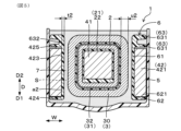
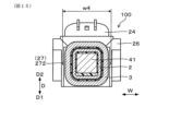
図1は、実施形態1にかかる、点火コイルの断面を示す説明図である。FIG. 1 is an explanatory diagram showing a cross section of an ignition coil according to a first embodiment. 図2は、実施形態1にかかる、点火コイルのコイル組付体の断面を示す説明図である。FIG. 2 is an explanatory diagram showing a cross section of a coil assembly of an ignition coil according to the first embodiment. 図3は、実施形態1にかかる、二次コイル、外側コア、コアカバー、充填樹脂等の周辺の断面を拡大して示す説明図である。FIG. 3 is an explanatory diagram showing an enlarged cross section of the secondary coil, the outer core, the core cover, the filling resin, and the like according to the first embodiment. 図4は、実施形態1にかかる、図3のIV-IV線に相当する、点火コイルの軸方向の高電圧側の位置の断面を示す説明図である。FIG. 4 is an explanatory diagram showing a cross section of the ignition coil at a position on the high voltage side in the axial direction, which corresponds to line IV-IV in FIG. 3, according to the first embodiment. 図5は、実施形態1にかかる、図3のV-V線に相当する、点火コイルの軸方向の低電圧側の位置の断面を示す説明図である。FIG. 5 is an explanatory diagram showing a cross section of the ignition coil at a position on the low-voltage side in the axial direction, which corresponds to line VV in FIG. 3, according to the first embodiment. 図6は、実施形態1にかかる、一次コイル、一次スプール、二次コイル、二次スプール、内側コア等が一体化されたコイル中間体を示す斜視図である。FIG. 6 is a perspective view showing a coil intermediate body in which a primary coil, a primary spool, a secondary coil, a secondary spool, an inner core, and the like are integrated together according to the first embodiment. 図7は、実施形態1にかかる、コアカバーを示す斜視図である。FIG. 7 is a perspective view of a core cover according to the first embodiment. 図8は、実施形態1にかかる、二次コイルの各分割コイル部の位置と、各分割コイル部の位置の径方向に対向する充填樹脂の部位に生じる電界の強さとの関係を示すグラフである。FIG. 8 is a graph showing the relationship between the position of each split coil part of the secondary coil and the strength of the electric field generated in a portion of the filling resin radially opposite the position of each split coil part in the first embodiment. 図9は、実施形態2にかかる、外側コア及びコアカバーを示す斜視図である。FIG. 9 is a perspective view showing an outer core and a core cover according to the second embodiment. 図10は、実施形態2にかかる、図3のIV-IV線に相当する、点火コイルの軸方向の高電圧側の位置の断面を示す説明図である。FIG. 10 is an explanatory diagram showing a cross section of the ignition coil at a position on the high voltage side in the axial direction, which corresponds to the line IV-IV in FIG. 3, according to the second embodiment. 図11は、実施形態2にかかる、図3のV-V線に相当する、点火コイルの軸方向の高電圧側の位置の断面を示す説明図である。FIG. 11 is an explanatory diagram showing a cross section of the ignition coil at a position on the high voltage side in the axial direction, which corresponds to line VV in FIG. 3, according to the second embodiment. 図12は、実施形態3にかかる、コイル組付体をコイルケース内に配置した状態を示す説明図である。FIG. 12 is an explanatory diagram showing a state in which the coil assembly is disposed in a coil case according to the third embodiment. 図13は、実施形態3にかかる、コアカバーの軸方向の低電圧側の端部の周辺を示す説明図。FIG. 13 is an explanatory diagram showing the periphery of the end portion on the low-voltage side in the axial direction of the core cover according to the third embodiment. 図14は、実施形態4にかかる、一次コイル、一次スプール、二次コイル、二次スプール、内側コア等が一体化されたコイル中間体を、外側コアに装着されたコアカバーに組み付ける状態を示す説明図である。FIG. 14 is an explanatory diagram showing the state in which a coil intermediate body in which a primary coil, a primary spool, a secondary coil, a secondary spool, an inner core, etc. are integrated together in embodiment 4 is assembled to a core cover attached to an outer core. 図15は、実施形態4にかかる、一次コイル、一次スプール、二次コイル、二次スプール、内側コア等が一体化された他のコイル中間体を示す説明図である。FIG. 15 is an explanatory diagram showing another coil intermediate body in which a primary coil, a primary spool, a secondary coil, a secondary spool, an inner core, and the like are integrated together according to the fourth embodiment.

前述した内燃機関用の点火コイルにかかる好ましい実施形態について、図面を参照して説明する。
<実施形態1>
本形態の内燃機関用の点火コイル1は、図1に示すように、一次コイル2、二次スプール31、二次コイル3、内側コア41、外側コア42、コアカバー6、コイルケース5及び充填樹脂7を備える。一次コイル2は、通電及び通電の遮断が行われるものである。二次スプール31は、一次コイル2の外側に同心状に配置されている。二次コイル3は、二次スプール31の外周の径方向R及び軸方向Lに巻き付けられ、発生する電圧が軸方向Lの高電圧側L1に向けて高くなるものである。
A preferred embodiment of the above-mentioned ignition coil for an internal combustion engine will be described with reference to the drawings.
<Embodiment 1>
As shown in Fig. 1, an ignition coil 1 for an internal combustion engine according to this embodiment includes a primary coil 2, a secondary spool 31, a secondary coil 3, an inner core 41, an outer core 42, a core cover 6, a coil case 5, and a filled resin 7. The primary coil 2 is adapted to turn on and off current. The secondary spool 31 is arranged concentrically on the outside of the primary coil 2. The secondary coil 3 is wound around the outer periphery of the secondary spool 31 in the radial direction R and the axial direction L, and the generated voltage increases toward the high voltage side L1 in the axial direction L.

図2~図5に示すように、内側コア41は、一次コイル2の内側に配置されている。外側コア42は、内側コア41の側面411の外側において軸方向Lに平行に配置された一対の側面コア部421と、内側コア41の端面412の外側において軸方向Lに直交する幅方向Wに平行に配置された一対の端面コア部422とによる四角環形状を有する。コアカバー6は、外側コア42の、少なくとも一対の側面コア部421における内側に位置する内側面423を含む表面に設けられている。コイルケース5は、外側コア42の開口側D2に位置する開口部53を有し、一次コイル2、二次スプール31、二次コイル3、内側コア41、外側コア42及びコアカバー6を収容するものである。充填樹脂7は、コイルケース5内の隙間に充填されている。 2 to 5, the inner core 41 is disposed inside the primary coil 2. The outer core 42 has a rectangular ring shape with a pair of side core parts 421 arranged parallel to the axial direction L on the outside of the side surface 411 of the inner core 41, and a pair of end surface core parts 422 arranged parallel to the width direction W perpendicular to the axial direction L on the outside of the end surface 412 of the inner core 41. The core cover 6 is provided on the surface of the outer core 42, including the inner side surface 423 located on the inside of at least a pair of side surface core parts 421. The coil case 5 has an opening 53 located on the opening side D2 of the outer core 42, and houses the primary coil 2, the secondary spool 31, the secondary coil 3, the inner core 41, the outer core 42, and the core cover 6. The filling resin 7 is filled in the gaps in the coil case 5.

図3~図5に示すように、二次コイル3における、軸方向Lの高電圧側L1に位置する部位の径方向Rの平均厚みu1は、軸方向Lの低電圧側L2に位置する部位の径方向Rの平均厚みu2に比べて小さい。コアカバー6における、一対の側面コア部421の軸方向Lの高電圧側L1に位置する内側面423に設けられた部位の、軸方向Lに直交する断面内の平均断面積a1は、コアカバー6における、一対の側面コア部421の軸方向Lの低電圧側L2に位置する内側面423に設けられた部位の、軸方向Lに直交する断面内の平均断面積a2に比べて大きい。 As shown in Figures 3 to 5, the average thickness u1 in the radial direction R of the secondary coil 3 at the high-voltage side L1 in the axial direction L is smaller than the average thickness u2 in the radial direction R of the low-voltage side L2 in the axial direction L. The average cross-sectional area a1 in the cross section perpendicular to the axial direction L of the core cover 6 at the inner surface 423 at the high-voltage side L1 in the axial direction L of the pair of side core portions 421 is larger than the average cross-sectional area a2 in the cross section perpendicular to the axial direction L of the core cover 6 at the inner surface 423 at the low-voltage side L2 in the axial direction L of the pair of side core portions 421.

以下に、本形態の点火コイル1について詳説する。
(点火コイル1)
図1に示すように、点火コイル1は、車両の内燃機関としてのエンジンにおいて、シリンダヘッドカバー8に配置され、シリンダヘッドに配置されたスパークプラグから、シリンダヘッドの燃焼室内に火花放電を発生させるために用いられる。本形態の点火コイル1は、車載用のものである。点火コイル1は、一次コイル2、二次コイル3、コイルケース5等によって構成されたコイル本体部11と、コイル本体部11から突出して、二次コイル3とスパークプラグとを高圧端子45及びバネ46を介して電気的に接続するためのジョイント部12とを有する。コイル本体部11は、シリンダヘッドカバー8に配置され、ジョイント部12は、シリンダヘッドカバー8のプラグホール81に配置される。
The ignition coil 1 of this embodiment will be described in detail below.
(Ignition coil 1)
As shown in Fig. 1, an ignition coil 1 is disposed in a cylinder head cover 8 in an engine as an internal combustion engine of a vehicle, and is used to generate a spark discharge in a combustion chamber of the cylinder head from a spark plug disposed in the cylinder head. The ignition coil 1 of this embodiment is for mounting on a vehicle. The ignition coil 1 has a coil body 11 constituted by a primary coil 2, a secondary coil 3, a coil case 5, etc., and a joint portion 12 protruding from the coil body 11 for electrically connecting the secondary coil 3 and the spark plug via a high-voltage terminal 45 and a spring 46. The coil body 11 is disposed in the cylinder head cover 8, and the joint portion 12 is disposed in a plug hole 81 of the cylinder head cover 8.

(軸方向L,装着方向D,幅方向W)
図1~図7に示すように、軸方向Lとは、一次コイル2及び二次コイル3の中心軸線が延びる方向のことをいう。軸方向Lにおいて、二次コイル3に高電圧が生じる側を高電圧側L1といい、高電圧側L1の反対側を低電圧側L2という。装着方向Dとは、軸方向Lに直交する方向であって、コイルケース5の底部52と開口部53とが並ぶ方向のことをいう。コイルケース5の装着方向Dにおいて、底部52が位置し、スパークプラグが配置される側を底側D1といい、底側D1の反対側であって開口部53が位置する側を開口側D2という。また、軸方向L及び装着方向Dの双方に直交する方向を幅方向Wという。
(Axial direction L, mounting direction D, width direction W)
1 to 7, the axial direction L refers to the direction in which the central axes of the primary coil 2 and the secondary coil 3 extend. The side opposite to the high-voltage side L1 is referred to as the high-voltage side L1, and the side opposite to the high-voltage side L1 is referred to as the low-voltage side L2. In the mounting direction D of the coil case 5, the side on which the bottom portion 52 is located and on which the spark plug is arranged is called the bottom side D1, and the side on the opposite side of the bottom side D1 on which the opening 53 is arranged is called the bottom side D2. The side where the opening is located is referred to as the opening side D2. Also, the direction perpendicular to both the axial direction L and the mounting direction D is referred to as the width direction W.

(径方向R,周方向C)
一次コイル2及び二次コイル3の中心軸線から放射状に広がる方向のことを径方向Rという。一次コイル2及び二次コイル3の中心軸線の周りの方向のことを周方向Cという。本形態の一次コイル2、二次コイル3等は四角筒状に形成されており、本形態の周方向Cは、四角環状の周方向Cとなる。また、装着方向D及び幅方向Wは、径方向Rに含まれる。
(Radial direction R, circumferential direction C)
The direction extending radially from the central axis of the primary coil 2 and the secondary coil 3 is called the radial direction R. The direction around the central axis of the primary coil 2 and the secondary coil 3 is called the circumferential direction C. In this embodiment, the primary coil 2, the secondary coil 3, etc. are formed in a rectangular tube shape, and the circumferential direction C in this embodiment is the circumferential direction C of the rectangular ring shape. The mounting direction D and the width direction W are included in the radial direction R.

(一次コイル2)
図1~図5に示すように、一次コイル2は、巻線としてのマグネットワイヤを、一次スプール21の筒部22の外周面に巻き付けることによって形成されている。一次コイル2は、導電性の導体と、導体の周りに設けられた絶縁性の被覆層とによって形成されている。一次コイル2は、エンジン制御装置からの指令を受けたイグナイタ43のスイッチング素子によって、通電及び通電の遮断が繰り返されるものである。
(Primary coil 2)
1 to 5, the primary coil 2 is formed by winding a magnet wire as a winding around the outer circumferential surface of the cylindrical portion 22 of the primary spool 21. The primary coil 2 is formed of a conductive conductor and an insulating coating layer provided around the conductor. The primary coil 2 is repeatedly energized and cut off by a switching element of an igniter 43 that receives a command from the engine control device.

(二次コイル3)
図1~図5に示すように、二次コイル3は、一次コイル2の外側において、一次コイル2と同軸状に配置されている。二次コイル3は、巻線としてのマグネットワイヤを、二次スプール31の筒部32の外周面に巻き付けることによって形成されている。二次コイル3は、導電性の導体と、導体の周りに設けられた絶縁性の被覆層とによって形成されている。
(Secondary coil 3)
1 to 5, the secondary coil 3 is disposed coaxially with the primary coil 2 on the outside of the primary coil 2. The secondary coil 3 is formed by winding a magnet wire as a winding around the outer circumferential surface of the cylindrical portion 32 of the secondary spool 31. The secondary coil 3 is formed of a conductive conductor and an insulating coating layer provided around the conductor.

二次コイル3の巻線は一次コイル2の巻線よりも細く、二次コイル3の巻線数は一次コイル2の巻線数よりも多い。二次コイル3は、一次コイル2への通電が遮断されたときに、相互誘導作用による誘導起電力を発生させるものである。一次コイル2及び二次コイル3の中心軸線は、コイルケース5の開口部53に対して直交する方向に向けられている。二次コイル3の巻線の低電圧側L2の端部は、イグナイタ43における、グラウンド又は電源の端子に接続されている。二次コイル3の巻線の高電圧側L1の端部は、スパークプラグの中心側電極に繋がる高圧端子45に接続されている。 The secondary coil 3 has a thinner winding than the primary coil 2, and the number of windings is greater than that of the primary coil 2. The secondary coil 3 generates an induced electromotive force by mutual induction when the current to the primary coil 2 is cut off. The central axes of the primary coil 2 and secondary coil 3 are oriented in a direction perpendicular to the opening 53 of the coil case 5. The low-voltage side L2 end of the secondary coil 3 winding is connected to the ground or power supply terminal of the igniter 43. The high-voltage side L1 end of the secondary coil 3 winding is connected to a high-voltage terminal 45 that is connected to the center electrode of the spark plug.

(内側コア41)
図2及び図3に示すように、一次コイル2の内側(内周側)には、一次コイル2及び二次コイル3によって生じる磁束を通過させるための内側コア41が配置されている。本形態の内側コア41は、軟磁性材料からなる板状の電磁鋼板が複数積層されて形成されている。内側コア41は、直方体形状に形成されており、軸方向Lに対して平行な4つの側面411と、軸方向Lに対して垂直な2つの端面412とを有する。なお、内側コア41は、軟磁性材料からなる粉末が圧縮成形されて形成されたものであってもよい。
(Inner core 41)
2 and 3, an inner core 41 is disposed inside (on the inner circumferential side) of the primary coil 2 to allow magnetic flux generated by the primary coil 2 and the secondary coil 3 to pass therethrough. The inner core 41 in this embodiment is formed by laminating a plurality of plate-shaped electromagnetic steel sheets made of a soft magnetic material. The inner core 41 is formed in a rectangular parallelepiped shape and has four side faces 411 parallel to the axial direction L and two end faces 412 perpendicular to the axial direction L. The inner core 41 may be formed by compression molding powder made of a soft magnetic material.

(外側コア42)
図2~図5に示すように、二次コイル3の外側(外周側)には、一次コイル2及び二次コイル3によって生じる磁束を通過させるための外側コア42が配置されている。本形態の外側コア42は、軟磁性材料からなる板状の電磁鋼板が複数積層されて形成されている。外側コア42は、装着方向Dから見た断面において、内側コア41を内側に配置する四角環形状に形成されている。なお、外側コア42は、軟磁性材料からなる粉末が圧縮成形されて形成されたものであってもよい。
(Outer core 42)
2 to 5, an outer core 42 is disposed on the outside (outer periphery) of the secondary coil 3 to allow magnetic flux generated by the primary coil 2 and the secondary coil 3 to pass therethrough. The outer core 42 in this embodiment is formed by laminating a plurality of plate-shaped electromagnetic steel sheets made of a soft magnetic material. The outer core 42 is formed in a square ring shape with the inner core 41 disposed on the inside in a cross section seen from the mounting direction D. The outer core 42 may be formed by compression molding powder made of a soft magnetic material.

外側コア42の一対の側面コア部421は、二次コイル3及び二次スプール31の外側であって幅方向Wの両側に位置している。外側コア42の一対の端面コア部422は、二次コイル3及び二次スプール31の軸方向Lの両側L1,L2に位置して一対の側面コア部421に連結されている。イグナイタ43は、外側コア42における、二次コイル3の軸方向Lの低電圧側L2に位置する端面コア部422に対面して配置される。イグナイタ43と端面コア部422との間には、隙間がほとんど形成されておらず、充填樹脂7がほとんど配置されていない。 The pair of side core parts 421 of the outer core 42 are located outside the secondary coil 3 and secondary spool 31 on both sides in the width direction W. The pair of end core parts 422 of the outer core 42 are located on both sides L1, L2 in the axial direction L of the secondary coil 3 and secondary spool 31 and are connected to the pair of side core parts 421. The igniter 43 is disposed facing the end core part 422 located on the low voltage side L2 of the secondary coil 3 in the axial direction L of the outer core 42. There is almost no gap between the igniter 43 and the end core part 422, and almost no filling resin 7 is disposed therein.

内側コア41と外側コア42とによって、磁束が通過する閉磁路が形成されている。内側コア41と外側コア42との間には、磁気飽和を防止するための永久磁石44が配置されている。 The inner core 41 and the outer core 42 form a closed magnetic path through which magnetic flux passes. A permanent magnet 44 is disposed between the inner core 41 and the outer core 42 to prevent magnetic saturation.

(イグナイタ43)
図1及び図2に示すように、点火コイル1は、エンジン制御装置からの指令を受けて、一次コイル2に通電及び通電の遮断を繰り返し行うイグナイタ43を備える。イグナイタ43は、一次コイル2及び二次コイル3の軸方向Lにおいて、外側コア42の端面コア部422の低電圧側L2に対面して配置されている。イグナイタ43は、コイルケース5に装着されるコネクタ部24と外側コア42の端面コア部422との間に配置されている。イグナイタ43は、スイッチング回路を形成するスイッチング素子等の電子部品が設けられた回路形成部と、回路形成部に一体化された放熱板と、回路形成部及び放熱板を覆うモールド樹脂と、回路形成部からモールド樹脂の外部に引き出されたイグナイタ導体431とを有する。
(Igniter 43)
1 and 2, the ignition coil 1 includes an igniter 43 that repeatedly energizes and cuts off the primary coil 2 in response to a command from an engine control device. The igniter 43 is disposed facing the low-voltage side L2 of the end surface core portion 422 of the outer core 42 in the axial direction L of the primary coil 2 and the secondary coil 3. The igniter 43 is disposed between the connector portion 24 attached to the coil case 5 and the end surface core portion 422 of the outer core 42. The igniter 43 includes a circuit forming portion provided with electronic components such as switching elements that form a switching circuit, a heat sink integrated with the circuit forming portion, a molded resin that covers the circuit forming portion and the heat sink, and an igniter conductor 431 that is drawn out from the circuit forming portion to the outside of the molded resin.

(一次スプール21)
図1~図5に示すように、一次スプール21の外周には、一次コイル2が巻き付けられている。一次スプール21は、熱可塑性樹脂の成形品によって形成されている。一次スプール21は、一次コイル2が巻き付けられた筒形状を有する筒部22を有する。本形態においては、一次スプール21とコネクタ部24とがスプール成形体210として一体成形されている。スプール成形体210は、四角形状の筒部22と、筒部22の軸方向Lの両端に形成された鍔部221と、コネクタ部24と、筒部22とコネクタ部24とを中継する中継部23とを有する。なお、コネクタ部24は、コネクタとして、一次スプール21の筒部22と別体に形成してもよい。
(Primary spool 21)
As shown in Figs. 1 to 5, the primary coil 2 is wound around the outer periphery of the primary spool 21. The primary spool 21 is formed by a molded product of a thermoplastic resin. The primary spool 21 has a cylindrical tubular portion 22 around which the primary coil 2 is wound. In this embodiment, the primary spool 21 and the connector portion 24 are integrally molded as a spool molded body 210. The spool molded body 210 has a rectangular tubular portion 22, flange portions 221 formed on both ends of the tubular portion 22 in the axial direction L, the connector portion 24, and a relay portion 23 that relays the tubular portion 22 and the connector portion 24. The connector portion 24 may be formed as a connector separately from the tubular portion 22 of the primary spool 21.

一次コイル2の巻線は、一次スプール21の筒部22における、鍔部221同士の間の外周面に巻き付けられている。コネクタ部24には、イグナイタ43におけるイグナイタ導体431に接続されるコネクタ導体25が、インサート成形によって設けられている。コネクタ部24は、コイルケース5の外部に突出する状態に形成されている。複数のイグナイタ導体431と複数のコネクタ導体25とは、半田付け、溶接等によって互いに接合されている。また、複数のイグナイタ導体431は、一次コイル2の巻線の両端部に接続された導体、及び二次コイル3の巻線の低電圧側L2の端部に接続された導体と、半田付け、溶接等によって互いに接合されている。 The winding of the primary coil 2 is wound around the outer circumferential surface between the flanges 221 of the tubular portion 22 of the primary spool 21. The connector portion 24 is provided with a connector conductor 25 connected to the igniter conductor 431 of the igniter 43 by insert molding. The connector portion 24 is formed in a state in which it protrudes outside the coil case 5. The multiple igniter conductors 431 and the multiple connector conductors 25 are joined to each other by soldering, welding, etc. In addition, the multiple igniter conductors 431 are joined to the conductors connected to both ends of the winding of the primary coil 2 and to the conductor connected to the end of the low-voltage side L2 of the winding of the secondary coil 3 by soldering, welding, etc.

(二次スプール31)
図1~図5に示すように、二次スプール31の外周には、二次コイル3が巻き付けられている。二次スプール31は、熱可塑性樹脂の成形品によって形成されている。二次スプール31は、四角筒形状を有する筒部32と、軸方向Lの複数箇所において筒部32の全周において外側に突出する複数の鍔部33とを有する。鍔部33は、筒部32の外周を、軸方向Lに並ぶ複数の凹部(スロット)321に仕切っている。二次スプール31の筒部32における、軸方向Lの高電圧側L1に位置する凹部321を形成する部分の径方向Rの厚みの一部は、軸方向Lの低電圧側L2に位置する凹部321を形成する部分の径方向Rの厚みよりも大きい。
(Secondary spool 31)
As shown in Figs. 1 to 5, the secondary coil 3 is wound around the outer periphery of the secondary spool 31. The secondary spool 31 is formed by molding a thermoplastic resin. The secondary spool 31 has a cylindrical portion 32 having a rectangular cylindrical shape and a plurality of flange portions 33 that protrude outward around the entire circumference of the cylindrical portion 32 at a plurality of locations in the axial direction L. The flange portions 33 divide the outer periphery of the cylindrical portion 32 into a plurality of recesses (slots) 321 arranged in the axial direction L. A part of the thickness in the radial direction R of the portion forming the recess 321 located on the high voltage side L1 in the axial direction L in the cylindrical portion 32 of the secondary spool 31 is larger than the thickness in the radial direction R of the portion forming the recess 321 located on the low voltage side L2 in the axial direction L.

図3に示すように、軸方向Lの高電圧側L1に位置する複数の凹部321の軸方向Lの幅は、軸方向Lの低電圧側L2に位置する複数の凹部321の軸方向Lの幅よりも小さい。本形態においては、複数の凹部321の軸方向Lの幅は、軸方向Lの高電圧側L1に位置するものほど小さい。鍔部33には、二次コイル3の巻線が隣接する凹部321の間を渡るための渡り溝が適宜形成されている。 As shown in FIG. 3, the width in the axial direction L of the multiple recesses 321 located on the high-voltage side L1 in the axial direction L is smaller than the width in the axial direction L of the multiple recesses 321 located on the low-voltage side L2 in the axial direction L. In this embodiment, the width in the axial direction L of the multiple recesses 321 is smaller as they are located on the high-voltage side L1 in the axial direction L. The flange portion 33 is appropriately formed with a transition groove for the winding of the secondary coil 3 to cross between adjacent recesses 321.

二次コイル3の巻線は、鍔部33同士の間に形成された複数の凹部321に、分割コイル部30として順次巻き付けられている。図4に示すように、軸方向Lの高電圧側L1に位置する複数の凹部321に配置された分割コイル部30の径方向Rの平均厚みu1は、図5に示すように、軸方向Lの低電圧側L2に位置する複数の凹部321に配置された分割コイル部30の径方向Rの平均厚みu2に比べて小さい。換言すれば、軸方向Lの高電圧側L1に位置する複数の凹部321に巻き付けられた二次コイル3の巻線は、軸方向Lの低電圧側L2に位置する複数の凹部321に巻き付けられた二次コイル3の巻線に比べて、径方向Rに薄く巻き付けられている。 The winding of the secondary coil 3 is wound in sequence as a split coil section 30 around a plurality of recesses 321 formed between the flanges 33. As shown in FIG. 4, the average thickness u1 in the radial direction R of the split coil section 30 arranged in the plurality of recesses 321 located on the high-voltage side L1 of the axial direction L is smaller than the average thickness u2 in the radial direction R of the split coil section 30 arranged in the plurality of recesses 321 located on the low-voltage side L2 of the axial direction L as shown in FIG. 5. In other words, the winding of the secondary coil 3 wound around the plurality of recesses 321 located on the high-voltage side L1 of the axial direction L is wound thinner in the radial direction R than the winding of the secondary coil 3 wound around the plurality of recesses 321 located on the low-voltage side L2 of the axial direction L.

ここで、軸方向Lの高電圧側L1に位置する複数の凹部321に配置された分割コイル部30の径方向Rの平均厚みu1は、二次コイル3の軸方向Lの全長における中心位置よりも高電圧側L1に位置する複数の凹部321に配置された分割コイル部30の平均厚みu1とすればよい。軸方向Lの低電圧側L2に位置する複数の凹部321に配置された分割コイル部30の径方向Rの平均厚みu2は、二次コイル3の軸方向Lの全長における中心位置よりも低電圧側L2に位置する複数の凹部321に配置された分割コイル部30の平均厚みu2とすればよい。 Here, the average thickness u1 in the radial direction R of the split coil parts 30 arranged in the multiple recesses 321 located on the high-voltage side L1 in the axial direction L may be set to the average thickness u1 of the split coil parts 30 arranged in the multiple recesses 321 located on the high-voltage side L1 of the center position of the secondary coil 3 in the entire length in the axial direction L. The average thickness u2 in the radial direction R of the split coil parts 30 arranged in the multiple recesses 321 located on the low-voltage side L2 in the axial direction L may be set to the average thickness u2 of the split coil parts 30 arranged in the multiple recesses 321 located on the low-voltage side L2 of the axial direction L of the secondary coil 3 in the entire length in the axial direction L.

二次コイル3の軸方向Lの全長における中心位置が含まれる凹部321に配置された分割コイル部30は、高電圧側L1の平均厚みu1及び低電圧側L2の平均厚みu2から除いて考えればよい。平均厚みu1,u2は、複数の分割コイル部30の厚みの平均値とすればよい。 The split coil section 30 arranged in the recess 321 that includes the center position of the entire length of the secondary coil 3 in the axial direction L may be excluded from the average thickness u1 of the high-voltage side L1 and the average thickness u2 of the low-voltage side L2. The average thicknesses u1 and u2 may be the average values of the thicknesses of the multiple split coil sections 30.

本形態においては、分割コイル部30の径方向Rの厚みは、軸方向Lの高電圧側L1に位置するものほど小さい。また、複数の凹部321に巻き付けられた二次コイル3の巻線の巻き数は、軸方向Lの高電圧側L1に位置する凹部321ほど少ない。そして、二次コイル3の外周と外側コア42の側面コア部421との間の距離は、軸方向Lの高電圧側L1に行くほど大きい。 In this embodiment, the thickness of the split coil section 30 in the radial direction R is smaller as it is located on the high voltage side L1 in the axial direction L. Also, the number of turns of the secondary coil 3 wound around the multiple recesses 321 is smaller for the recesses 321 located on the high voltage side L1 in the axial direction L. And the distance between the outer circumference of the secondary coil 3 and the side core section 421 of the outer core 42 is larger as it is located on the high voltage side L1 in the axial direction L.

(コアカバー6)
図4、図5及び図7に示すように、コアカバー6は、二次コイル3と外側コア42との間の隙間Sを小さくして充填樹脂7の充填量を少なくし、二次コイル3と外側コア42との絶縁性をより適切に確保するために用いられる。コアカバー6は、外側コア42の内側及び装着方向Dの底側D1及び開口側D2の各表面に設けられている。より具体的には、コアカバー6は、一対の側面コア部421における内側に位置する内側面423に配置された一対の内側カバー部61と、一対の内側カバー部61に繋がって、一対の側面コア部421における、装着方向Dの開口側D2に位置する開口面425に配置された一対の開口側カバー部63とを有する。また、本形態のコアカバー6は、一対の内側カバー部61に繋がって、一対の側面コア部421における、装着方向Dの底側D1に位置する底面424に配置された一対の底側カバー部62も有する。
(Core cover 6)
As shown in Fig. 4, Fig. 5 and Fig. 7, the core cover 6 is used to reduce the gap S between the secondary coil 3 and the outer core 42, thereby reducing the amount of the filling resin 7, and to more appropriately ensure insulation between the secondary coil 3 and the outer core 42. The core cover 6 is provided on the inside of the outer core 42 and on each surface of the bottom side D1 and the opening side D2 in the mounting direction D. More specifically, the core cover 6 has a pair of inner cover parts 61 arranged on the inner side surface 423 located on the inside of the pair of side core parts 421, and a pair of opening side cover parts 63 connected to the pair of inner cover parts 61 and arranged on the opening surface 425 located on the opening side D2 in the mounting direction D of the pair of side core parts 421. The core cover 6 of this embodiment also has a pair of bottom side cover parts 62 connected to the pair of inner cover parts 61 and arranged on the bottom surface 424 located on the bottom side D1 in the mounting direction D of the pair of side core parts 421.

また、内側カバー部61は、一対の側面コア部421における内側面423に配置された部分と繋がって、軸方向Lの高電圧側L1の端面コア部422における内側面423にも配置されている。開口側カバー部63は、一対の側面コア部421における開口面425に配置された部分と繋がって、軸方向Lの高電圧側L1の端面コア部422における開口面425にも配置されている。底側カバー部62は、一対の側面コア部421における底面424に配置された部分と繋がって、軸方向Lの高電圧側L1の端面コア部422における底面424にも配置されている。換言すれば、コアカバー6は、一対の側面コア部421及び高電圧側L1の端面コア部422における、内側面423、開口面425及び底面424に対面して配置されている。 The inner cover part 61 is connected to the part arranged on the inner side surface 423 of the pair of side core parts 421, and is also arranged on the inner side surface 423 of the end face core part 422 on the high voltage side L1 in the axial direction L. The opening side cover part 63 is connected to the part arranged on the opening surface 425 of the pair of side core parts 421, and is also arranged on the opening surface 425 of the end face core part 422 on the high voltage side L1 in the axial direction L. The bottom side cover part 62 is connected to the part arranged on the bottom surface 424 of the pair of side core parts 421, and is also arranged on the bottom surface 424 of the end face core part 422 on the high voltage side L1 in the axial direction L. In other words, the core cover 6 is arranged facing the inner side surface 423, the opening surface 425, and the bottom surface 424 of the pair of side core parts 421 and the end face core part 422 on the high voltage side L1.

図4に示すように、一対の内側カバー部61における、軸方向Lの高電圧側L1に位置する部位の幅方向Wの平均厚みt1は、図5に示すように、一対の内側カバー部61における、軸方向Lの低電圧側L2に位置する部位の幅方向Wの平均厚みt2に比べて大きい。この構成により、二次コイル3の径方向Rの厚みが小さくなる高電圧側L1の部位においては、内側カバー部61の幅方向Wの厚みが大きくなり、二次コイル3と内側カバー部61との間の軸方向Lの各部位における、充填樹脂7が充填される隙間Sの大きさのばらつきを抑制することができる。 As shown in FIG. 4, the average thickness t1 in the width direction W of the pair of inner cover parts 61 located on the high-voltage side L1 in the axial direction L is greater than the average thickness t2 in the width direction W of the pair of inner cover parts 61 located on the low-voltage side L2 in the axial direction L as shown in FIG. 5. With this configuration, the thickness of the inner cover part 61 in the width direction W is greater in the high-voltage side L1 part where the thickness of the secondary coil 3 in the radial direction R is smaller, and the variation in the size of the gap S filled with the filling resin 7 at each part in the axial direction L between the secondary coil 3 and the inner cover part 61 can be suppressed.

ここで、一対の内側カバー部61における、軸方向Lの高電圧側L1に位置する部位の幅方向Wの平均厚みt1は、内側カバー部61の軸方向Lの全長における中心位置よりも高電圧側L1に位置する部位の厚みの平均値とすればよい。一対の内側カバー部61における、軸方向Lの低電圧側L2に位置する部位の幅方向Wの平均厚みt2は、内側カバー部61の軸方向Lの全長における中心位置よりも低電圧側L2に位置する部位の厚みの平均値とすればよい。 The average thickness t1 in the width direction W of the portion of the pair of inner cover parts 61 located on the high-voltage side L1 in the axial direction L may be the average value of the thicknesses of the portion located on the high-voltage side L1 of the inner cover part 61 relative to the center position over the entire length of the inner cover part 61 in the axial direction L. The average thickness t2 in the width direction W of the portion of the pair of inner cover parts 61 located on the low-voltage side L2 in the axial direction L may be the average value of the thicknesses of the portion located on the low-voltage side L2 of the inner cover part 61 relative to the center position over the entire length of the inner cover part 61 in the axial direction L.

図3に示すように、本形態のコアカバー6においては、一対の内側カバー部61の幅方向Wの厚みは、軸方向Lの高電圧側L1に位置する部位ほど大きい。換言すれば、二次コイル3の径方向Rの厚みが、軸方向Lの高電圧側L1に位置する部位ほど小さくなる分だけ、一対の内側カバー部61の幅方向Wの厚みは、軸方向Lの高電圧側L1に位置する部位ほど大きい。また、内側カバー部61の内側に位置する面は、軸方向Lの高電圧側L1に行くほど、幅方向Wの内側に近づくテーパ状に形成されている。この構成により、二次コイル3と内側カバー部61との間の軸方向Lの各部位における、充填樹脂7が充填される隙間Sの大きさのばらつきをより効果的に抑制することができる。 As shown in FIG. 3, in the core cover 6 of this embodiment, the thickness in the width direction W of the pair of inner cover parts 61 is greater in the portion located on the high-voltage side L1 in the axial direction L. In other words, the thickness in the width direction W of the pair of inner cover parts 61 is greater in the portion located on the high-voltage side L1 in the axial direction L, to the extent that the thickness in the radial direction R of the secondary coil 3 is smaller in the portion located on the high-voltage side L1 in the axial direction L. In addition, the surface located on the inside of the inner cover part 61 is formed in a tapered shape that approaches the inside in the width direction W as it approaches the high-voltage side L1 in the axial direction L. With this configuration, it is possible to more effectively suppress the variation in the size of the gap S filled with the filling resin 7 at each portion in the axial direction L between the secondary coil 3 and the inner cover part 61.

図4及び図5に示すように、開口側カバー部63の装着方向Dの全体の寸法は、底側カバー部62の装着方向Dの寸法及び内側カバー部61の幅方向Wの寸法よりも大きい。本形態の開口側カバー部63は、装着方向Dに並ぶ複数のリブ631によって形成されている。より具体的には、内側カバー部61に繋がって、装着方向Dの底側D1と開口側D2とに2つのリブ631が並んで形成されており、2つのリブ631の間には、充填樹脂7が充填される溝部632が形成されている。 As shown in Figures 4 and 5, the overall dimension of the opening side cover part 63 in the mounting direction D is greater than the dimension of the bottom side cover part 62 in the mounting direction D and the dimension of the inner cover part 61 in the width direction W. In this embodiment, the opening side cover part 63 is formed by a plurality of ribs 631 aligned in the mounting direction D. More specifically, two ribs 631 are formed side by side on the bottom side D1 and the opening side D2 in the mounting direction D, connected to the inner cover part 61, and a groove part 632 in which the filling resin 7 is filled is formed between the two ribs 631.

開口側カバー部63における、外側コア42の開口面425と対向する面には、外側コア42へのコアカバー6の装着を容易にするための突起633が形成されている。底側カバー部62における、外側コア42の底面424と対向する面にも、外側コア42へのコアカバー6の装着を容易にするための突起621が形成されている。突起621,633は、コアカバー6の軸方向Lの複数箇所に形成されている。また、高電圧側L1の端面コア部422の内側(低電圧側L2)に配置された内側カバー部61の部分には、内側コア41が挿通される開口穴611が形成されている。 The surface of the opening side cover part 63 facing the opening surface 425 of the outer core 42 has a protrusion 633 for facilitating attachment of the core cover 6 to the outer core 42. The surface of the bottom side cover part 62 facing the bottom surface 424 of the outer core 42 also has a protrusion 621 for facilitating attachment of the core cover 6 to the outer core 42. The protrusions 621, 633 are formed at multiple locations in the axial direction L of the core cover 6. In addition, an opening hole 611 through which the inner core 41 is inserted is formed in the part of the inner cover part 61 arranged inside (low voltage side L2) of the end face core part 422 of the high voltage side L1.

図7に示すように、外側コア42は、一対の端面コア部422において分断された2部品を組み合わせて形成されている。コアカバー6は、高電圧側L1の端面コア部422に対向する部分において分断された2部品を組み合わせて形成されている。 As shown in FIG. 7, the outer core 42 is formed by combining two parts separated at a pair of end face core portions 422. The core cover 6 is formed by combining two parts separated at a portion facing the end face core portions 422 of the high voltage side L1.

(コイルケース5)
図1及び図4~図6に示すように、コイルケース5は、熱可塑性樹脂の成形品として形成されている。コイルケース5は、一次コイル2、二次コイル3、内側コア41、外側コア42、イグナイタ43等を収容する収容部51を有する。コイルケース5には、コイル組付体10を収容部51に配置するための開口部53が形成されており、開口部53は、収容部51の装着方向Dの開口側D2の端部に形成されている。コイル組付体10は、一次コイル2、一次スプール21、二次コイル3、二次スプール31、内側コア41、外側コア42、コアカバー6、イグナイタ43等が組み付けられて形成される。また、液状の充填樹脂7は、開口部53からコイルケース5内の隙間に注入される。
(Coil case 5)
As shown in Fig. 1 and Fig. 4 to Fig. 6, the coil case 5 is formed as a molded product of a thermoplastic resin. The coil case 5 has a housing portion 51 that houses the primary coil 2, the secondary coil 3, the inner core 41, the outer core 42, the igniter 43, etc. The coil case 5 has an opening 53 for disposing the coil assembly 10 in the housing portion 51, and the opening 53 is formed at the end of the opening side D2 of the housing portion 51 in the mounting direction D. The coil assembly 10 is formed by assembling the primary coil 2, the primary spool 21, the secondary coil 3, the secondary spool 31, the inner core 41, the outer core 42, the core cover 6, the igniter 43, etc. In addition, the liquid filling resin 7 is injected into the gap in the coil case 5 from the opening 53.

図1及び図6に示すように、コイルケース5の一部には、イグナイタ43を外部のエンジン制御装置と電気接続するための、スプール成形体210のコネクタ部24が配置されている。スプール成形体210は、一次スプール21の筒部22に内側コア41を配置するとともに、コネクタ部24にコネクタ導体25を配置した、樹脂のインサート成形を行って形成されている。 As shown in Figures 1 and 6, the connector portion 24 of the spool molding 210 is disposed in a portion of the coil case 5 to electrically connect the igniter 43 to an external engine control device. The spool molding 210 is formed by resin insert molding in which the inner core 41 is disposed in the cylindrical portion 22 of the primary spool 21 and the connector conductor 25 is disposed in the connector portion 24.

コイルケース5には、スプール成形体210のコネクタ部24が装着される装着用切欠き56が形成されている。コイルケース5の一部の壁部は、コネクタ部24のコネクタ壁部241によって形成される。コネクタ壁部241の、装着方向Dの底側D1の端部及び幅方向Wの両側の端部には、装着用切欠き56の縁部を両側から挟持する挟持部242が形成されている。 The coil case 5 is formed with an attachment notch 56 into which the connector portion 24 of the spool molding 210 is attached. A portion of the wall of the coil case 5 is formed by the connector wall portion 241 of the connector portion 24. The end of the connector wall portion 241 on the bottom side D1 in the attachment direction D and on both ends in the width direction W are formed with clamping portions 242 that clamp the edge of the attachment notch 56 from both sides.

また、図1に示すように、コイルケース5の装着方向Dの底側D1に位置する底部52には、ジョイント部12を構成するタワー部57が形成されている。タワー部57には、点火コイル1とプラグホール81との間を封止するためのシールラバー58が装着されている。 As shown in FIG. 1, a tower portion 57 that constitutes the joint portion 12 is formed on the bottom portion 52 located on the bottom side D1 of the mounting direction D of the coil case 5. A seal rubber 58 is attached to the tower portion 57 to seal the gap between the ignition coil 1 and the plug hole 81.

(充填樹脂7)
図1及び図3~図5に示すように、充填樹脂7は、一次コイル2、一次スプール21、二次コイル3、二次スプール31、内側コア41、外側コア42、イグナイタ43等の点火コイル1の構成部品を、コイルケース5内に絶縁して固着するための絶縁固着樹脂として用いられる。充填樹脂7は、熱硬化性樹脂によって構成されている。コイルケース5内に、一次コイル2、一次スプール21、二次コイル3、二次スプール31、内側コア41、外側コア42、コアカバー6、イグナイタ43等が組み付けられたコイル組付体10が配置された後に、このコイルケース5内の隙間に液状の熱硬化性樹脂が注入され、この液状の熱硬化性樹脂が硬化される。熱硬化性樹脂からなる充填樹脂7によって、コイルケース5内の一次コイル2、一次スプール21、二次コイル3、二次スプール31、内側コア41、外側コア42、コアカバー6、イグナイタ43等が絶縁された状態で互いに固着される。
(Filling resin 7)
As shown in FIG. 1 and FIG. 3 to FIG. 5, the filled resin 7 is used as an insulating and fixing resin for insulating and fixing the components of the ignition coil 1, such as the primary coil 2, the primary spool 21, the secondary coil 3, the secondary spool 31, the inner core 41, the outer core 42, and the igniter 43, in the coil case 5. The filled resin 7 is made of a thermosetting resin. After the coil assembly 10, in which the primary coil 2, the primary spool 21, the secondary coil 3, the secondary spool 31, the inner core 41, the outer core 42, the core cover 6, the igniter 43, and the like are assembled, is arranged in the coil case 5, liquid thermosetting resin is injected into the gaps in the coil case 5, and the liquid thermosetting resin is hardened. The filled resin 7 made of a thermosetting resin fixes the primary coil 2, the primary spool 21, the secondary coil 3, the secondary spool 31, the inner core 41, the outer core 42, the core cover 6, the igniter 43, and the like in the coil case 5 to each other in an insulated state.

(作用効果)
本形態の内燃機関用の点火コイル1においては、外側コア42の表面に設けられたコアカバー6の形状に工夫をしている。具体的には、コアカバー6の軸方向Lに直交する断面内の断面積を、軸方向Lの高電圧側L1に位置する部位ほど大きくしている。特に、本形態においては、内側カバー部61の断面積を、軸方向Lの高電圧側L1に位置する部位ほど大きくしている。一方、二次コイル3の径方向Rの厚みは、軸方向Lの高電圧側L1に位置する部位ほど小さい。また、二次コイル3と内側カバー部61との間の幅方向Wの隙間Sの断面積、及びこの隙間Sに充填された充填樹脂7の断面積は、軸方向Lの全体においてほぼ均一である。
(Action and Effect)
In the ignition coil 1 for an internal combustion engine of this embodiment, the shape of the core cover 6 provided on the surface of the outer core 42 is devised. Specifically, the cross-sectional area of the core cover 6 in a cross section perpendicular to the axial direction L is made larger toward the high-voltage side L1 in the axial direction L. In particular, in this embodiment, the cross-sectional area of the inner cover part 61 is made larger toward the high-voltage side L1 in the axial direction L. On the other hand, the thickness of the secondary coil 3 in the radial direction R is smaller toward the high-voltage side L1 in the axial direction L. In addition, the cross-sectional area of the gap S in the width direction W between the secondary coil 3 and the inner cover part 61 and the cross-sectional area of the filling resin 7 filled in this gap S are almost uniform throughout the axial direction L.

これらの構成により、二次コイル3と内側カバー部61との間の隙間Sの大きさを、軸方向Lの低電圧側L2の部位から高電圧側L1の部位まで、できるだけ均一にすることができる。これにより、二次コイル3と内側カバー部61との間に充填される充填樹脂7の部位の厚みを、軸方向Lの低電圧側L2の部位から高電圧側L1の部位まで、できるだけ均一にすることができる。その結果、点火コイル1の使用時の冷熱サイクルにおいて、充填樹脂7に生じる熱膨張量及び熱収縮量を、軸方向Lの低電圧側L2の部位から高電圧側L1の部位まで、できるだけ均一にすることができる。 These configurations allow the size of the gap S between the secondary coil 3 and the inner cover part 61 to be as uniform as possible from the low voltage side L2 to the high voltage side L1 in the axial direction L. This allows the thickness of the portion of the filled resin 7 filled between the secondary coil 3 and the inner cover part 61 to be as uniform as possible from the low voltage side L2 to the high voltage side L1 in the axial direction L. As a result, the amount of thermal expansion and contraction that occurs in the filled resin 7 during the cooling and heating cycles when the ignition coil 1 is in use can be made as uniform as possible from the low voltage side L2 to the high voltage side L1 in the axial direction L.

それ故、本形態の内燃機関用の点火コイル1によれば、二次コイル3と内側カバー部61との間に充填された充填樹脂7の部位において熱応力の集中が生じにくくすることができる。また、この充填樹脂7の部位に亀裂が生じにくくし、点火コイル1における絶縁性を長く確保することができる。 Therefore, according to the ignition coil 1 for an internal combustion engine of this embodiment, it is possible to make it difficult for thermal stress to concentrate in the area of the filled resin 7 filled between the secondary coil 3 and the inner cover part 61. In addition, it is possible to make it difficult for cracks to occur in the area of the filled resin 7, and it is possible to ensure the insulation of the ignition coil 1 for a long time.

図8には、二次スプール31の複数の凹部321に配置された二次コイル3の各分割コイル部30の位置と、各分割コイル部30の位置の径方向Rに対向する充填樹脂7の部位に生じる電界の強さ[kV/mm]との関係を、従来の点火コイル(比較品)と本形態の点火コイル1(実施品)とについて示す。分割コイル部30の位置は、軸方向Lの低電圧側L2に位置するものから順に、N1~N6として示す。 Figure 8 shows the relationship between the position of each split coil section 30 of the secondary coil 3 arranged in the multiple recesses 321 of the secondary spool 31 and the electric field strength [kV/mm] generated at the portion of the filled resin 7 facing the position of each split coil section 30 in the radial direction R for a conventional ignition coil (comparison product) and the ignition coil 1 of this embodiment (implemented product). The positions of the split coil sections 30 are indicated as N1 to N6, starting from the one located on the low-voltage side L2 in the axial direction L.

従来の点火コイルは、各凹部321に配置された分割コイル部30の径方向Rの厚みが、軸方向Lの低電圧側L2から高電圧側L1の全体においてほぼ一定である場合について示す。本形態の点火コイル1においては、各凹部321に配置された分割コイル部30の径方向Rの厚みは、軸方向Lの高電圧側L1に位置するものほど小さい。 In the conventional ignition coil, the thickness in the radial direction R of the split coil section 30 arranged in each recess 321 is almost constant throughout the entire area from the low voltage side L2 to the high voltage side L1 in the axial direction L. In the ignition coil 1 of this embodiment, the thickness in the radial direction R of the split coil section 30 arranged in each recess 321 is smaller as it is located closer to the high voltage side L1 in the axial direction L.

各分割コイル部30の位置は、各分割コイル部30の軸方向Lの中心位置として示す。充填樹脂7の部位に生じる電界の強さは、二次コイル3の各分割コイル部30と外側コア42との間にコアカバー6の内側カバー部61及び充填樹脂7が配置されることによって形成される疑似コンデンサに生じる電界の強さを示す。 The position of each split coil section 30 is shown as the center position of the split coil section 30 in the axial direction L. The strength of the electric field generated at the location of the filled resin 7 indicates the strength of the electric field generated in the pseudo capacitor formed by disposing the inner cover section 61 of the core cover 6 and the filled resin 7 between each split coil section 30 of the secondary coil 3 and the outer core 42.

図8において、従来の点火コイル(比較品)においては、二次コイル3の高電圧側L1の部位ほど、電圧が高くなるために、軸方向Lの高電圧側L1に位置する部位ほど、充填樹脂7に生じる電界の強さが顕著に大きくなる。また、軸方向Lの低電圧側L2の部位と高電圧側L1の部位とにおける、充填樹脂7に生じる電界の強さの差が顕著である。一方、本形態の点火コイル1(実施品)においては、軸方向Lの低電圧側L2の部位と高電圧側L1の部位とにおける、充填樹脂7に生じる電界の強さの差が小さくなっている。 In FIG. 8, in a conventional ignition coil (comparison product), the voltage is higher in the high-voltage side L1 of the secondary coil 3, so the strength of the electric field generated in the filled resin 7 is significantly stronger in the portion located on the high-voltage side L1 in the axial direction L. Also, there is a significant difference in the strength of the electric field generated in the filled resin 7 between the low-voltage side L2 portion and the high-voltage side L1 portion in the axial direction L. On the other hand, in the ignition coil 1 (embodiment product) of this embodiment, there is a smaller difference in the strength of the electric field generated in the filled resin 7 between the low-voltage side L2 portion and the high-voltage side L1 portion in the axial direction L.

さらに、本形態の点火コイル1においては、コアカバー6を構成する材料として、充填樹脂7を構成する材料よりも比誘電率が小さいものを使用することにより、軸方向Lの低電圧側L2の部位と高電圧側L1の部位とにおける、充填樹脂7に生じる電界の強さの差をより小さくすることが可能である。 Furthermore, in this embodiment of the ignition coil 1, by using a material for the core cover 6 that has a smaller relative dielectric constant than the material for the filled resin 7, it is possible to further reduce the difference in the strength of the electric field generated in the filled resin 7 between the low-voltage side L2 and the high-voltage side L1 in the axial direction L.

具体的には、本形態のコアカバー6は、ポリプロピレン樹脂によって構成されており、本形態の充填樹脂7は、エポキシ樹脂によって構成されている。ポリプロピレン樹脂の比誘電率は、2.2~2.6程度であり、本形態において用いるエポキシ樹脂の比誘電率は、ポリプロピレン樹脂の比誘電率に比べて大きく、2.5~6.0程度である。 Specifically, the core cover 6 in this embodiment is made of polypropylene resin, and the filling resin 7 in this embodiment is made of epoxy resin. The relative dielectric constant of polypropylene resin is about 2.2 to 2.6, and the relative dielectric constant of the epoxy resin used in this embodiment is larger than the relative dielectric constant of polypropylene resin, being about 2.5 to 6.0.

本形態の点火コイル1においては、軸方向Lの高電圧側L1に位置する分割コイル部30と内側コア41部との間の隙間Sにおいて、内側カバー部61が占有する体積が大きくなる一方、充填樹脂7が占有する体積が小さくなる。これにより、本形態の点火コイル1においては、軸方向Lの高電圧側L1に位置する充填樹脂7に生じる電界の強さが小さくなり、軸方向Lの低電圧側L2の部位と高電圧側L1の部位とにおける、充填樹脂7に生じる電界の強さの差がより緩和されると考えられる。 In the ignition coil 1 of this embodiment, in the gap S between the split coil portion 30 located on the high-voltage side L1 in the axial direction L and the inner core 41 portion, the volume occupied by the inner cover portion 61 becomes large, while the volume occupied by the filled resin 7 becomes small. As a result, in the ignition coil 1 of this embodiment, the strength of the electric field generated in the filled resin 7 located on the high-voltage side L1 in the axial direction L becomes small, and it is thought that the difference in the strength of the electric field generated in the filled resin 7 between the part on the low-voltage side L2 and the part on the high-voltage side L1 in the axial direction L is further alleviated.

このことによっても、二次コイル3と内側カバー部61との間に充填された充填樹脂7の部位の劣化を抑制し、点火コイル1における絶縁性を長く維持することができる。 This also helps prevent deterioration of the portion of the filling resin 7 between the secondary coil 3 and the inner cover portion 61, and allows the insulation of the ignition coil 1 to be maintained for a long time.

<実施形態2>
本形態は、図9~図11に示すように、二次コイル3と内側カバー部61との間の隙間Sの大きさの、軸方向Lにおけるばらつきを小さくする構成を、実施形態1のコアカバー6とは異なるコアカバー6によって実現する例を示す。
<Embodiment 2>
As shown in Figures 9 to 11, this embodiment shows an example of a configuration in which the variation in the size of the gap S between the secondary coil 3 and the inner cover portion 61 in the axial direction L is reduced by using a core cover 6 different from the core cover 6 of embodiment 1.

本形態のコアカバー6においては、内側カバー部61と開口側カバー部63とによる角部64は、外側に膨らむ曲面状に形成されている。曲面状の角部64は、曲面状の部位を有する形状であればよく、内側カバー部61と、開口側カバー部63の装着方向Dの開口側D2の面が傾斜した傾斜面との間に形成されていてもよい。また、角部64の曲率半径は、軸方向Lに直交する断面内において変化していてもよく、曲率半径の平均値として表せばよい。 In this embodiment of the core cover 6, the corner 64 formed by the inner cover part 61 and the opening side cover part 63 is formed in a curved shape that bulges outward. The curved corner 64 may have any shape that has a curved portion, and may be formed between the inner cover part 61 and an inclined surface on the opening side D2 of the opening side cover part 63 in the mounting direction D. In addition, the radius of curvature of the corner 64 may vary in a cross section perpendicular to the axial direction L, and may be expressed as the average value of the radius of curvature.

本形態の開口側カバー部63は、複数のリブ631として形成されておらず、一つの塊形状として形成されている。そして、図10に示すように、コアカバー6における、軸方向Lの高電圧側L1に位置する部位の角部64の平均曲率半径r1は、図11に示すように、コアカバー6における、軸方向Lの低電圧側L2に位置する部位の角部64の平均曲率半径r2に比べて小さい。この構成により、二次コイル3の径方向Rの厚みが小さくなる高電圧側L1の部位においては、開口側カバー部63の幅方向Wの厚みが大きくなる。その結果、本形態においては、点火コイル1の使用時の冷熱サイクルにおいて、充填樹脂7に生じる熱膨張量及び熱収縮量を、軸方向Lの低電圧側L2の部位から高電圧側L1の部位まで、より均一に近づけることができる。 The opening side cover part 63 in this embodiment is not formed as a plurality of ribs 631, but is formed as a single block shape. As shown in FIG. 10, the average radius of curvature r1 of the corners 64 of the core cover 6 located on the high voltage side L1 in the axial direction L is smaller than the average radius of curvature r2 of the corners 64 of the core cover 6 located on the low voltage side L2 in the axial direction L as shown in FIG. 11. With this configuration, the thickness of the opening side cover part 63 in the width direction W is large in the high voltage side L1 part where the thickness of the secondary coil 3 in the radial direction R is small. As a result, in this embodiment, the amount of thermal expansion and contraction that occurs in the filling resin 7 during the cooling and heating cycle when the ignition coil 1 is used can be made more uniform from the low voltage side L2 part to the high voltage side L1 part in the axial direction L.

ここで、コアカバー6における、軸方向Lの高電圧側L1に位置する部位の角部64の平均曲率半径r1は、内側カバー部61と開口側カバー部63との角部64の軸方向Lの全長における中心位置よりも高電圧側L1に位置する部位の曲率半径の平均値とすればよい。コアカバー6における、軸方向Lの低電圧側L2に位置する部位の角部64の平均曲率半径r2は、内側カバー部61と開口側カバー部63との角部64の軸方向Lの全長における中心位置よりも低電圧側L2に位置する部位の曲率半径の平均値とすればよい。 The average radius of curvature r1 of the corners 64 of the core cover 6 located on the high-voltage side L1 in the axial direction L may be the average value of the radii of curvature of the parts located on the high-voltage side L1 of the center position of the corners 64 between the inner cover part 61 and the opening side cover part 63 over the entire length in the axial direction L. The average radius of curvature r2 of the corners 64 of the core cover 6 located on the low-voltage side L2 in the axial direction L may be the average value of the radii of curvature of the parts located on the low-voltage side L2 of the center position of the corners 64 between the inner cover part 61 and the opening side cover part 63 over the entire length in the axial direction L.

本形態のコアカバー6においては、内側カバー部61と開口側カバー部63とによる角部64の曲率半径は、軸方向Lの高電圧側L1に位置する部位ほど小さい。この構成により、点火コイル1の使用時の冷熱サイクルにおいて、充填樹脂7に生じる熱膨張量及び熱収縮量を、軸方向Lの低電圧側L2の部位から高電圧側L1の部位まで、さらに均一に近づけることができる。 In this embodiment of the core cover 6, the radius of curvature of the corner 64 formed by the inner cover part 61 and the opening side cover part 63 is smaller in the portion located on the high voltage side L1 in the axial direction L. With this configuration, the amount of thermal expansion and contraction that occurs in the filled resin 7 during the cooling and heating cycles when the ignition coil 1 is in use can be made more uniform from the portion on the low voltage side L2 to the portion on the high voltage side L1 in the axial direction L.

本形態のコアカバー6の構成は、実施形態1に示した一対の内側カバー部61の幅方向Wの厚みが軸方向Lの各部位において異なる構成と併用する。また、本形態の開口側カバー部63は、図9の二点鎖線によって示すように、実施形態1に示した複数のリブ631として形成してもよい。 The configuration of the core cover 6 in this embodiment is used in combination with the configuration of the pair of inner cover parts 61 shown in embodiment 1 in which the thickness in the width direction W varies at each location in the axial direction L. In addition, the opening side cover part 63 in this embodiment may be formed as a plurality of ribs 631 shown in embodiment 1, as shown by the two-dot chain line in Figure 9.

本形態の点火コイル1における、その他の構成、作用効果等については、実施形態1の構成、作用効果等と同様である。また、本形態においても、実施形態1に示した符号と同一の符号が示す構成要素は、実施形態1の構成要素と同様である。 Other configurations, functions, and effects of the ignition coil 1 of this embodiment are the same as those of the first embodiment. In this embodiment, the components denoted by the same reference numerals as those in the first embodiment are the same as those in the first embodiment.

<実施形態3>
本形態は、図12及び図13に示すように、二次コイル3とコアカバー6との間の隙間Sに充填された充填樹脂7の部位に亀裂が生じたときであっても、この亀裂が一次コイル2の巻線端部201等の導体まで伸展することを防止する工夫をした例を示す。
<Embodiment 3>
This embodiment shows an example in which, as shown in Figures 12 and 13, even if a crack occurs in the portion of the filling resin 7 that fills the gap S between the secondary coil 3 and the core cover 6, the crack is prevented from extending to conductors such as the winding end 201 of the primary coil 2.

本形態の一次スプール21は、充填樹脂7に生じた亀裂の伸展を防止する形状を有する。図6、図12及び図13に示すように、一次スプール21は、筒部22から装着方向Dの開口側D2に突出して、コアカバー6における開口側カバー部63の、軸方向Lの外側としての低電圧側L2に対向する突出部26を有する。突出部26は、一対の開口側カバー部63の軸方向Lの低電圧側L2の端部に対向して形成されている。一次スプール21における、突出部26よりも軸方向Lの低電圧側L2に位置する部位には、一次コイル2の巻線端部201を保持する保持部261が設けられている。 The primary spool 21 of this embodiment has a shape that prevents the propagation of cracks that occur in the filled resin 7. As shown in Figures 6, 12, and 13, the primary spool 21 has a protruding portion 26 that protrudes from the cylindrical portion 22 to the opening side D2 in the mounting direction D and faces the low-voltage side L2, which is the outer side in the axial direction L, of the opening side cover portion 63 of the core cover 6. The protruding portion 26 is formed facing the end of the low-voltage side L2 in the axial direction L of the pair of opening side cover portions 63. A holding portion 261 that holds the winding end 201 of the primary coil 2 is provided at a portion of the primary spool 21 that is located closer to the low-voltage side L2 in the axial direction L than the protruding portion 26.

図12に示すように、開口側カバー部63の、側面コア部421における開口面425からコイルケース5の開口部53の側、換言すれば開口面425から装着方向Dの開口側D2への突出量x1は、一次スプール21の突出部26の、開口面425から装着方向Dの開口側D2への突出量x2に比べて小さい。 As shown in FIG. 12, the amount of protrusion x1 of the opening side cover portion 63 from the opening surface 425 of the side core portion 421 to the opening 53 side of the coil case 5, in other words, from the opening surface 425 to the opening side D2 in the mounting direction D, is smaller than the amount of protrusion x2 of the protruding portion 26 of the primary spool 21 from the opening surface 425 to the opening side D2 in the mounting direction D.

本形態の点火コイル1の使用時の冷熱サイクルにおいては、二次コイル3と内側カバー部61との間の隙間Sに充填された充填樹脂7の部位に亀裂が生じたときには、突出部26によって、この亀裂が軸方向Lの低電圧側L2に伸展することが防止される。これにより、亀裂が、一次コイル2の巻線端部201等の導体まで伸展することが防止される。 When the ignition coil 1 of this embodiment is used in a cooling/heating cycle, if a crack occurs in the portion of the filling resin 7 that fills the gap S between the secondary coil 3 and the inner cover portion 61, the protrusion 26 prevents the crack from propagating to the low-voltage side L2 in the axial direction L. This prevents the crack from propagating to the conductors such as the winding end 201 of the primary coil 2.

本形態の点火コイル1における、その他の構成、作用効果等については、実施形態1,2の構成、作用効果等と同様である。また、本形態においても、実施形態1,2に示した符号と同一の符号が示す構成要素は、実施形態1,2の構成要素と同様である。 Other configurations, functions, and effects of the ignition coil 1 of this embodiment are the same as those of the first and second embodiments. In this embodiment, the components denoted by the same reference numerals as those in the first and second embodiments are the same as those in the first and second embodiments.

<実施形態4>
本形態は、図12及び図14に示すように、外側コア42に装着されたコアカバー6に、一次コイル2、一次スプール21、二次コイル3、二次スプール31、内側コア41等が一体化されたコイル中間体100を組み付けた状態を適切に維持する工夫をした例を示す。本形態においては、コイル中間体100を構成する一次スプール21の形状に工夫をしている。
<Embodiment 4>
12 and 14, this embodiment shows an example in which a coil intermediate body 100 in which the primary coil 2, the primary spool 21, the secondary coil 3, the secondary spool 31, the inner core 41, etc. are integrated with a core cover 6 attached to an outer core 42 is appropriately maintained in an assembled state. In this embodiment, the shape of the primary spool 21 constituting the coil intermediate body 100 is devised.

一次スプール21には、筒部22から幅方向Wへ突出し、コアカバー6における一対の内側カバー部61の間に嵌め込まれて、一対の内側カバー部61の間隔を維持するための間隔維持部27が形成されている。本形態の間隔維持部27は、一次スプール21の、筒部22と中継部23との境界部分において、筒部22から幅方向Wの両側に突出する一対のテーパリブ271によって形成されている。 The primary spool 21 is formed with a spacing maintaining portion 27 that protrudes from the tubular portion 22 in the width direction W and is fitted between a pair of inner cover portions 61 of the core cover 6 to maintain the spacing between the pair of inner cover portions 61. In this embodiment, the spacing maintaining portion 27 is formed by a pair of tapered ribs 271 that protrude from the tubular portion 22 on both sides in the width direction W at the boundary between the tubular portion 22 and the relay portion 23 of the primary spool 21.

間隔維持部27としての一対のテーパリブ271の幅方向Wの幅は、装着方向Dの開口側D2から底側D1に行くに連れて小さく変化している。換言すれば、テーパリブ271の幅方向Wの端面は、底側D1に行くに連れて、幅方向Wの内側に位置するテーパ面として形成されている。一方、コアカバー6における一対の内側カバー部61の幅方向Wの内側面612は、装着方向Dに平行な直線状の表面として形成されている。 The width in the width direction W of the pair of tapered ribs 271 serving as the spacing maintaining portion 27 becomes smaller as it moves from the opening side D2 to the bottom side D1 in the mounting direction D. In other words, the end faces in the width direction W of the tapered ribs 271 are formed as tapered surfaces that are positioned inward in the width direction W as they move toward the bottom side D1. On the other hand, the inner surfaces 612 in the width direction W of the pair of inner cover portions 61 of the core cover 6 are formed as linear surfaces parallel to the mounting direction D.

一対のテーパリブ271における装着方向Dの底側D1の端部の幅方向Wの幅をw1、一対のテーパリブ271における装着方向Dの開口側D2の端部の幅方向Wの幅をw2、一対の内側カバー部61の内側面612の幅方向Wの幅をw3としたとき、w1<w3<w2の関係にある。そして、図12及び図13に示すように、一次コイル2、一次スプール21、二次コイル3、二次スプール31、内側コア41等が組み付けられたコイル中間体100を、外側コア42に装着されたコアカバー6内に配置するときには、一対のテーパリブ271がコアカバー6の一対の内側カバー部61の間に嵌め込まれる。 When the width in the width direction W of the end of the bottom side D1 in the mounting direction D of the pair of tapered ribs 271 is w1, the width in the width direction W of the end of the opening side D2 in the mounting direction D of the pair of tapered ribs 271 is w2, and the width in the width direction W of the inner surface 612 of the pair of inner cover parts 61 is w3, the relationship is w1 < w3 < w2. Then, as shown in Figures 12 and 13, when the coil intermediate body 100 assembled with the primary coil 2, primary spool 21, secondary coil 3, secondary spool 31, inner core 41, etc. is placed in the core cover 6 attached to the outer core 42, the pair of tapered ribs 271 are fitted between the pair of inner cover parts 61 of the core cover 6.

コアカバー6の軸方向Lの低電圧側L2の部位は、U形状のコアカバー6の端部に位置するため、成形型によるコアカバー6の成形後に、内側へ変形することが想定される。そのため、コイル中間体100を外側コア42に装着されたコアカバー6に組み付けるときに、間隔維持部27によって、一対の内側カバー部61の間隔を適切に維持することができる。これにより、二次コイル3と一対の内側カバー部61との間の隙間Sに充填される充填樹脂7の幅方向Wの厚みを適切に維持することができる。 The portion of the low-voltage side L2 in the axial direction L of the core cover 6 is located at the end of the U-shaped core cover 6, and is therefore expected to deform inward after the core cover 6 is molded using a molding die. Therefore, when the coil intermediate 100 is assembled to the core cover 6 attached to the outer core 42, the spacing between the pair of inner cover parts 61 can be appropriately maintained by the spacing maintaining part 27. This makes it possible to appropriately maintain the thickness in the width direction W of the filling resin 7 filled in the gap S between the secondary coil 3 and the pair of inner cover parts 61.

また、図15に示すように、間隔維持部27は、一対のテーパリブ271の代わりに、一次スプール21の幅方向Wの側面に設けられた一対の変形用の突起272によって構成してもよい。この場合には、一対の突起272の先端同士の間における幅方向Wの幅w4を、一対の内側カバー部61の内側面612の幅方向Wの幅w3よりも小さくする。そして、コイル中間体100を、外側コア42におけるコアカバー6の内側に挿入するときに、一対の突起272が塑性変形又は弾性変形することによって、一対の内側カバー部61の間隔を適切に維持することができる。 Also, as shown in FIG. 15, the spacing maintaining portion 27 may be formed by a pair of deformation protrusions 272 provided on the side surface of the primary spool 21 in the width direction W, instead of the pair of tapered ribs 271. In this case, the width w4 in the width direction W between the tips of the pair of protrusions 272 is made smaller than the width w3 in the width direction W of the inner side surface 612 of the pair of inner cover portions 61. Then, when the coil intermediate body 100 is inserted inside the core cover 6 of the outer core 42, the pair of protrusions 272 undergo plastic or elastic deformation, thereby appropriately maintaining the spacing between the pair of inner cover portions 61.

本形態の点火コイル1における、その他の構成、作用効果等については、実施形態1~3の構成、作用効果等と同様である。また、本形態においても、実施形態1~3に示した符号と同一の符号が示す構成要素は、実施形態1~3の構成要素と同様である。 Other configurations, functions, and effects of the ignition coil 1 of this embodiment are the same as those of the first to third embodiments. In this embodiment, the components denoted by the same reference numerals as those in the first to third embodiments are the same as those in the first to third embodiments.

本発明は、各実施形態のみに限定されるものではなく、その要旨を逸脱しない範囲においてさらに異なる実施形態を構成することが可能である。また、本発明は、様々な変形例、均等範囲内の変形例等を含む。さらに、本発明から想定される様々な構成要素の組み合わせ、形態等も本発明の技術思想に含まれる。 The present invention is not limited to the embodiments, and further different embodiments can be constructed without departing from the gist of the present invention. The present invention also includes various modified examples, modifications within the scope of equivalents, etc. Furthermore, the combinations and forms of the various components envisioned from the present invention are also included in the technical concept of the present invention.

1 点火コイル
2 一次コイル
3 二次コイル
31 二次スプール
41 内側コア
42 外側コア
5 コイルケース
6 コアカバー
7 充填樹脂
REFERENCE SIGNS LIST 1 ignition coil 2 primary coil 3 secondary coil 31 secondary spool 41 inner core 42 outer core 5 coil case 6 core cover 7 filling resin

Claims (6)

一次コイル(2)と、
前記一次コイルの外側に同心状に配置された二次スプール(31)と、
前記二次スプールの外周の径方向(R)及び軸方向(L)に巻き付けられ、発生する電圧が前記軸方向の高電圧側(L1)に向けて高くなる二次コイル(3)と、
前記一次コイルの内側に配置された内側コア(41)と、
前記内側コアの側面(411)の外側において前記軸方向に平行に配置された一対の側面コア部(421)と、前記内側コアの端面(412)の外側において前記軸方向に直交する幅方向(W)に平行に配置された一対の端面コア部(422)とによる四角環形状を有する外側コア(42)と、
前記外側コアの、少なくとも一対の前記側面コア部における内側に位置する内側面(423)を含む表面に設けられたコアカバー(6)と、
前記外側コアの開口側(D2)に位置する開口部(53)を有し、前記一次コイル、前記二次スプール、前記二次コイル、前記内側コア、前記外側コア及び前記コアカバーを収容するコイルケース(5)と、
前記コイルケース内の隙間に充填された充填樹脂(7)と、を備え、
前記二次コイルにおける、前記軸方向の高電圧側に位置する部位の前記径方向の平均厚み(u1)は、前記二次コイルにおける、前記軸方向の低電圧側(L2)に位置する部位の前記径方向の平均厚み(u2)に比べて小さく、
前記コアカバーにおける、一対の前記側面コア部の前記軸方向の高電圧側の前記内側面に設けられた部位の、前記軸方向に直交する断面内の平均断面積(a1)は、前記コアカバーにおける、一対の前記側面コア部の前記軸方向の低電圧側の前記内側面に設けられた部位の、前記軸方向に直交する断面内の平均断面積(a2)に比べて大きい、内燃機関用の点火コイル(1)。
A primary coil (2);
a secondary spool (31) arranged concentrically outside the primary coil;
A secondary coil (3) that is wound around the outer periphery of the secondary spool in a radial direction (R) and an axial direction (L), and a voltage generated therein increases toward a high voltage side (L1) in the axial direction;
an inner core (41) disposed inside the primary coil;
an outer core (42) having a rectangular ring shape including a pair of side core portions (421) arranged parallel to the axial direction outside the side surface (411) of the inner core, and a pair of end surface core portions (422) arranged parallel to a width direction (W) perpendicular to the axial direction outside the end surface (412) of the inner core;
A core cover (6) provided on a surface of the outer core including an inner surface (423) located on the inside of at least a pair of the side core portions;
a coil case (5) having an opening (53) located on an opening side (D2) of the outer core and housing the primary coil, the secondary spool, the secondary coil, the inner core, the outer core, and the core cover;
A filling resin (7) is filled in the gap in the coil case,
the average radial thickness (u1) of the secondary coil at a portion located on the high-voltage side in the axial direction is smaller than the average radial thickness (u2) of the secondary coil at a portion located on the low-voltage side (L2) in the axial direction;
An ignition coil (1) for an internal combustion engine, wherein an average cross-sectional area (a1) of a portion of the core cover provided on the inner surface of the pair of side core portions on the high-voltage side in the axial direction, in a cross section perpendicular to the axial direction, is larger than an average cross-sectional area (a2) of a portion of the core cover provided on the inner surface of the pair of side core portions on the low-voltage side in the axial direction, in a cross section perpendicular to the axial direction.
前記コアカバーは、一対の前記側面コア部における前記内側面に配置された一対の内側カバー部(61)と、一対の前記内側カバー部に繋がって、一対の前記側面コア部における、前記開口側に位置する開口面(425)に配置された一対の開口側カバー部(63)とを有しており、
一対の前記内側カバー部における、前記軸方向の高電圧側に位置する部位の前記幅方向の平均厚み(t1)は、一対の前記内側カバー部における、前記軸方向の低電圧側に位置する部位の前記幅方向の平均厚み(t2)に比べて大きい、請求項1に記載の内燃機関用の点火コイル。
The core cover has a pair of inner cover portions (61) arranged on the inner surfaces of the pair of side core portions, and a pair of opening side cover portions (63) connected to the pair of inner cover portions and arranged on opening surfaces (425) located on the opening side of the pair of side core portions,
2. The ignition coil for an internal combustion engine according to claim 1, wherein an average thickness (t1) in the width direction of a portion of the pair of inner cover parts that is located on a high-voltage side in the axial direction is larger than an average thickness (t2) in the width direction of a portion of the pair of inner cover parts that is located on a low-voltage side in the axial direction.
前記内側カバー部と前記開口側カバー部とによる角部(64)は、曲面状に形成されており、
前記軸方向の高電圧側に位置する部位の前記角部の平均曲率半径(r1)は、前記軸方向の低電圧側に位置する部位の前記角部の平均曲率半径(r2)に比べて小さい、請求項2に記載の内燃機関用の点火コイル。
A corner portion (64) formed by the inner cover portion and the opening side cover portion is formed in a curved shape,
3. The ignition coil for an internal combustion engine according to claim 2, wherein an average radius of curvature (r1) of the corners of a portion located on the high-voltage side in the axial direction is smaller than an average radius of curvature (r2) of the corners of a portion located on the low-voltage side in the axial direction.
前記二次スプールは、筒形状を有する筒部(32)と、前記軸方向の複数箇所において前記筒部の全周において外側に突出する複数の鍔部(33)とを有しており、
前記二次コイルは、前記鍔部同士の間に形成された複数の凹部(321)に、分割コイル部(30)として順次巻き付けられており、
前記軸方向の高電圧側に位置する複数の前記凹部に配置された前記分割コイル部の前記径方向の平均厚み(u1)は、前記軸方向の低電圧側に位置する複数の前記凹部に配置された前記分割コイル部の前記径方向の平均厚み(u2)に比べて小さい、請求項2又は3に記載の内燃機関用の点火コイル。
The secondary spool has a cylindrical portion (32) having a cylindrical shape and a plurality of flange portions (33) protruding outwardly around the entire circumference of the cylindrical portion at a plurality of locations in the axial direction,
The secondary coil is wound as split coil portions (30) in sequence around a plurality of recesses (321) formed between the flange portions,
4. An ignition coil for an internal combustion engine as described in claim 2 or 3, wherein the average radial thickness (u1) of the split coil portions arranged in the multiple recesses located on the high voltage side in the axial direction is smaller than the average radial thickness (u2) of the split coil portions arranged in the multiple recesses located on the low voltage side in the axial direction.
前記一次コイルが巻き付けられた筒形状を有する筒部(22)、及び前記筒部から突出して、前記コアカバーにおける前記開口側カバー部の、前記軸方向の外側に対向する突出部(26)を有する一次スプール(21)をさらに備え、
前記開口側カバー部の、前記開口面から前記コイルケースの前記開口部の側への突出量(x1)は、前記一次スプールの前記突出部の、前記開口面から前記コイルケースの前記開口部の側への突出量(x2)に比べて小さい、請求項2~4のいずれか1項に記載の内燃機関用の点火コイル。
a primary spool (21) having a cylindrical portion (22) around which the primary coil is wound, and a protrusion (26) protruding from the cylindrical portion and facing an outer side in the axial direction of the opening side cover portion of the core cover,
An ignition coil for an internal combustion engine as described in any one of claims 2 to 4, wherein a protrusion amount (x1) of the opening side cover portion from the opening surface toward the opening side of the coil case is smaller than a protrusion amount (x2) of the protrusion portion of the primary spool from the opening surface toward the opening side of the coil case.
前記一次スプールには、前記筒部から前記幅方向へ突出し、前記コアカバーにおける一対の前記内側カバー部の間に嵌め込まれて、一対の前記内側カバー部の間隔を維持するための間隔維持部(27)が形成されている、請求項5に記載の内燃機関用の点火コイル。 The ignition coil for an internal combustion engine according to claim 5, wherein the primary spool is formed with a spacing maintaining portion (27) that protrudes from the cylindrical portion in the width direction and is fitted between the pair of inner cover portions of the core cover to maintain the spacing between the pair of inner cover portions.
JP2021043322A 2021-03-17 2021-03-17 Ignition coil for internal combustion engine Active JP7559637B2 (en)

Priority Applications (1)

Application Number Priority Date Filing Date Title
JP2021043322A JP7559637B2 (en) 2021-03-17 2021-03-17 Ignition coil for internal combustion engine

Applications Claiming Priority (1)

Application Number Priority Date Filing Date Title
JP2021043322A JP7559637B2 (en) 2021-03-17 2021-03-17 Ignition coil for internal combustion engine

Publications (2)

Publication Number Publication Date
JP2022143012A JP2022143012A (en) 2022-10-03
JP7559637B2 true JP7559637B2 (en) 2024-10-02

Family

ID=83453811

Family Applications (1)

Application Number Title Priority Date Filing Date
JP2021043322A Active JP7559637B2 (en) 2021-03-17 2021-03-17 Ignition coil for internal combustion engine

Country Status (1)

Country Link
JP (1) JP7559637B2 (en)

Citations (4)

* Cited by examiner, † Cited by third party
Publication number Priority date Publication date Assignee Title
US20050212635A1 (en) 2004-03-24 2005-09-29 Visteon Global Technologies, Inc. Ignition coil with separating wall
JP2011171659A (en) 2010-02-22 2011-09-01 Denso Corp Ignition coil device
JP2013065743A (en) 2011-09-20 2013-04-11 Hitachi Automotive Systems Ltd Ignition coil for internal combustion engine
WO2016181517A1 (en) 2015-05-13 2016-11-17 三菱電機株式会社 Ignition coil for internal combustion engine

Patent Citations (4)

* Cited by examiner, † Cited by third party
Publication number Priority date Publication date Assignee Title
US20050212635A1 (en) 2004-03-24 2005-09-29 Visteon Global Technologies, Inc. Ignition coil with separating wall
JP2011171659A (en) 2010-02-22 2011-09-01 Denso Corp Ignition coil device
JP2013065743A (en) 2011-09-20 2013-04-11 Hitachi Automotive Systems Ltd Ignition coil for internal combustion engine
WO2016181517A1 (en) 2015-05-13 2016-11-17 三菱電機株式会社 Ignition coil for internal combustion engine

Also Published As

Publication number Publication date
JP2022143012A (en) 2022-10-03

Similar Documents

Publication Publication Date Title
EP1255260B1 (en) Stick-type ignition coil having improved structure against crack or dielectric discharge
US9117585B2 (en) Ignition coil
JP3777962B2 (en) Electromagnetic device and high voltage generator
US7626481B2 (en) Ignition coil
US20130291844A1 (en) Ignition coil
JP3550643B2 (en) Ignition coil for internal combustion engine
JP7559637B2 (en) Ignition coil for internal combustion engine
JP4554696B2 (en) Ignition device for internal combustion engine
CN113614357A (en) Ignition coil for internal combustion engine
CN113257550B (en) ignition coil
JP7543728B2 (en) Ignition coil for internal combustion engine
JP7666224B2 (en) Ignition coil for internal combustion engine
JP3587024B2 (en) Ignition coil for internal combustion engine
JP7505382B2 (en) Ignition coil for internal combustion engine
JP4032692B2 (en) Ignition coil
JP7484600B2 (en) Ignition coil for internal combustion engine
JP2008172162A (en) Soft magnetic material for ignition coil
JP2000208346A (en) Ignition coil for internal combustion engine and manufacturing method thereof
JP7567273B2 (en) Ignition coil for internal combustion engine
JP7593181B2 (en) Ignition coil for internal combustion engine
JP2008277459A (en) Ignition coil
JP7226009B2 (en) ignition coil
JP2004253818A (en) Ignition coil for internal combustion engine
JPH11204357A (en) Ignition coil for internal combustion engine
JP2007013004A (en) Ignition coil

Legal Events

Date Code Title Description
A621 Written request for application examination

Free format text: JAPANESE INTERMEDIATE CODE: A621

Effective date: 20240109

A977 Report on retrieval

Free format text: JAPANESE INTERMEDIATE CODE: A971007

Effective date: 20240802

TRDD Decision of grant or rejection written
A01 Written decision to grant a patent or to grant a registration (utility model)

Free format text: JAPANESE INTERMEDIATE CODE: A01

Effective date: 20240820

A61 First payment of annual fees (during grant procedure)

Free format text: JAPANESE INTERMEDIATE CODE: A61

Effective date: 20240902

R150 Certificate of patent or registration of utility model

Ref document number: 7559637

Country of ref document: JP

Free format text: JAPANESE INTERMEDIATE CODE: R150