JP7561512B2 - Information display device - Google Patents
Information display device Download PDFInfo
- Publication number
- JP7561512B2 JP7561512B2 JP2020067148A JP2020067148A JP7561512B2 JP 7561512 B2 JP7561512 B2 JP 7561512B2 JP 2020067148 A JP2020067148 A JP 2020067148A JP 2020067148 A JP2020067148 A JP 2020067148A JP 7561512 B2 JP7561512 B2 JP 7561512B2
- Authority
- JP
- Japan
- Prior art keywords
- light
- image
- display device
- image light
- polarizing plate
- Prior art date
- Legal status (The legal status is an assumption and is not a legal conclusion. Google has not performed a legal analysis and makes no representation as to the accuracy of the status listed.)
- Active
Links
Images


Classifications
-
- G—PHYSICS
- G02—OPTICS
- G02B—OPTICAL ELEMENTS, SYSTEMS OR APPARATUS
- G02B5/00—Optical elements other than lenses
- G02B5/30—Polarising elements
- G02B5/3025—Polarisers, i.e. arrangements capable of producing a definite output polarisation state from an unpolarised input state
-
- B—PERFORMING OPERATIONS; TRANSPORTING
- B60—VEHICLES IN GENERAL
- B60K—ARRANGEMENT OR MOUNTING OF PROPULSION UNITS OR OF TRANSMISSIONS IN VEHICLES; ARRANGEMENT OR MOUNTING OF PLURAL DIVERSE PRIME-MOVERS IN VEHICLES; AUXILIARY DRIVES FOR VEHICLES; INSTRUMENTATION OR DASHBOARDS FOR VEHICLES; ARRANGEMENTS IN CONNECTION WITH COOLING, AIR INTAKE, GAS EXHAUST OR FUEL SUPPLY OF PROPULSION UNITS IN VEHICLES
- B60K35/00—Instruments specially adapted for vehicles; Arrangement of instruments in or on vehicles
- B60K35/10—Input arrangements, i.e. from user to vehicle, associated with vehicle functions or specially adapted therefor
-
- B—PERFORMING OPERATIONS; TRANSPORTING
- B60—VEHICLES IN GENERAL
- B60K—ARRANGEMENT OR MOUNTING OF PROPULSION UNITS OR OF TRANSMISSIONS IN VEHICLES; ARRANGEMENT OR MOUNTING OF PLURAL DIVERSE PRIME-MOVERS IN VEHICLES; AUXILIARY DRIVES FOR VEHICLES; INSTRUMENTATION OR DASHBOARDS FOR VEHICLES; ARRANGEMENTS IN CONNECTION WITH COOLING, AIR INTAKE, GAS EXHAUST OR FUEL SUPPLY OF PROPULSION UNITS IN VEHICLES
- B60K35/00—Instruments specially adapted for vehicles; Arrangement of instruments in or on vehicles
- B60K35/20—Output arrangements, i.e. from vehicle to user, associated with vehicle functions or specially adapted therefor
- B60K35/21—Output arrangements, i.e. from vehicle to user, associated with vehicle functions or specially adapted therefor using visual output, e.g. blinking lights or matrix displays
- B60K35/22—Display screens
-
- B—PERFORMING OPERATIONS; TRANSPORTING
- B60—VEHICLES IN GENERAL
- B60K—ARRANGEMENT OR MOUNTING OF PROPULSION UNITS OR OF TRANSMISSIONS IN VEHICLES; ARRANGEMENT OR MOUNTING OF PLURAL DIVERSE PRIME-MOVERS IN VEHICLES; AUXILIARY DRIVES FOR VEHICLES; INSTRUMENTATION OR DASHBOARDS FOR VEHICLES; ARRANGEMENTS IN CONNECTION WITH COOLING, AIR INTAKE, GAS EXHAUST OR FUEL SUPPLY OF PROPULSION UNITS IN VEHICLES
- B60K35/00—Instruments specially adapted for vehicles; Arrangement of instruments in or on vehicles
- B60K35/20—Output arrangements, i.e. from vehicle to user, associated with vehicle functions or specially adapted therefor
- B60K35/21—Output arrangements, i.e. from vehicle to user, associated with vehicle functions or specially adapted therefor using visual output, e.g. blinking lights or matrix displays
- B60K35/23—Head-up displays [HUD]
-
- B—PERFORMING OPERATIONS; TRANSPORTING
- B60—VEHICLES IN GENERAL
- B60K—ARRANGEMENT OR MOUNTING OF PROPULSION UNITS OR OF TRANSMISSIONS IN VEHICLES; ARRANGEMENT OR MOUNTING OF PLURAL DIVERSE PRIME-MOVERS IN VEHICLES; AUXILIARY DRIVES FOR VEHICLES; INSTRUMENTATION OR DASHBOARDS FOR VEHICLES; ARRANGEMENTS IN CONNECTION WITH COOLING, AIR INTAKE, GAS EXHAUST OR FUEL SUPPLY OF PROPULSION UNITS IN VEHICLES
- B60K35/00—Instruments specially adapted for vehicles; Arrangement of instruments in or on vehicles
- B60K35/20—Output arrangements, i.e. from vehicle to user, associated with vehicle functions or specially adapted therefor
- B60K35/28—Output arrangements, i.e. from vehicle to user, associated with vehicle functions or specially adapted therefor characterised by the type of the output information, e.g. video entertainment or vehicle dynamics information; characterised by the purpose of the output information, e.g. for attracting the attention of the driver
-
- B—PERFORMING OPERATIONS; TRANSPORTING
- B60—VEHICLES IN GENERAL
- B60K—ARRANGEMENT OR MOUNTING OF PROPULSION UNITS OR OF TRANSMISSIONS IN VEHICLES; ARRANGEMENT OR MOUNTING OF PLURAL DIVERSE PRIME-MOVERS IN VEHICLES; AUXILIARY DRIVES FOR VEHICLES; INSTRUMENTATION OR DASHBOARDS FOR VEHICLES; ARRANGEMENTS IN CONNECTION WITH COOLING, AIR INTAKE, GAS EXHAUST OR FUEL SUPPLY OF PROPULSION UNITS IN VEHICLES
- B60K35/00—Instruments specially adapted for vehicles; Arrangement of instruments in or on vehicles
- B60K35/40—Instruments specially adapted for improving the visibility thereof to the user, e.g. fogging prevention or anti-reflection arrangements
- B60K35/425—Anti-reflection arrangements
-
- B—PERFORMING OPERATIONS; TRANSPORTING
- B60—VEHICLES IN GENERAL
- B60K—ARRANGEMENT OR MOUNTING OF PROPULSION UNITS OR OF TRANSMISSIONS IN VEHICLES; ARRANGEMENT OR MOUNTING OF PLURAL DIVERSE PRIME-MOVERS IN VEHICLES; AUXILIARY DRIVES FOR VEHICLES; INSTRUMENTATION OR DASHBOARDS FOR VEHICLES; ARRANGEMENTS IN CONNECTION WITH COOLING, AIR INTAKE, GAS EXHAUST OR FUEL SUPPLY OF PROPULSION UNITS IN VEHICLES
- B60K35/00—Instruments specially adapted for vehicles; Arrangement of instruments in or on vehicles
- B60K35/60—Instruments characterised by their location or relative disposition in or on vehicles
-
- B—PERFORMING OPERATIONS; TRANSPORTING
- B60—VEHICLES IN GENERAL
- B60K—ARRANGEMENT OR MOUNTING OF PROPULSION UNITS OR OF TRANSMISSIONS IN VEHICLES; ARRANGEMENT OR MOUNTING OF PLURAL DIVERSE PRIME-MOVERS IN VEHICLES; AUXILIARY DRIVES FOR VEHICLES; INSTRUMENTATION OR DASHBOARDS FOR VEHICLES; ARRANGEMENTS IN CONNECTION WITH COOLING, AIR INTAKE, GAS EXHAUST OR FUEL SUPPLY OF PROPULSION UNITS IN VEHICLES
- B60K35/00—Instruments specially adapted for vehicles; Arrangement of instruments in or on vehicles
- B60K35/80—Arrangements for controlling instruments
-
- B—PERFORMING OPERATIONS; TRANSPORTING
- B60—VEHICLES IN GENERAL
- B60R—VEHICLES, VEHICLE FITTINGS, OR VEHICLE PARTS, NOT OTHERWISE PROVIDED FOR
- B60R11/00—Arrangements for holding or mounting articles, not otherwise provided for
- B60R11/02—Arrangements for holding or mounting articles, not otherwise provided for for radio sets, television sets, telephones, or the like; Arrangement of controls thereof
-
- G—PHYSICS
- G02—OPTICS
- G02B—OPTICAL ELEMENTS, SYSTEMS OR APPARATUS
- G02B1/00—Optical elements characterised by the material of which they are made; Optical coatings for optical elements
- G02B1/10—Optical coatings produced by application to, or surface treatment of, optical elements
- G02B1/18—Coatings for keeping optical surfaces clean, e.g. hydrophobic or photo-catalytic films
-
- G—PHYSICS
- G02—OPTICS
- G02B—OPTICAL ELEMENTS, SYSTEMS OR APPARATUS
- G02B27/00—Optical systems or apparatus not provided for by any of the groups G02B1/00 - G02B26/00, G02B30/00
- G02B27/01—Head-up displays
- G02B27/0101—Head-up displays characterised by optical features
-
- G—PHYSICS
- G02—OPTICS
- G02B—OPTICAL ELEMENTS, SYSTEMS OR APPARATUS
- G02B27/00—Optical systems or apparatus not provided for by any of the groups G02B1/00 - G02B26/00, G02B30/00
- G02B27/01—Head-up displays
- G02B27/017—Head mounted
- G02B27/0172—Head mounted characterised by optical features
-
- G—PHYSICS
- G02—OPTICS
- G02B—OPTICAL ELEMENTS, SYSTEMS OR APPARATUS
- G02B27/00—Optical systems or apparatus not provided for by any of the groups G02B1/00 - G02B26/00, G02B30/00
- G02B27/28—Optical systems or apparatus not provided for by any of the groups G02B1/00 - G02B26/00, G02B30/00 for polarising
- G02B27/283—Optical systems or apparatus not provided for by any of the groups G02B1/00 - G02B26/00, G02B30/00 for polarising used for beam splitting or combining
-
- G—PHYSICS
- G02—OPTICS
- G02B—OPTICAL ELEMENTS, SYSTEMS OR APPARATUS
- G02B5/00—Optical elements other than lenses
- G02B5/30—Polarising elements
-
- B—PERFORMING OPERATIONS; TRANSPORTING
- B60—VEHICLES IN GENERAL
- B60K—ARRANGEMENT OR MOUNTING OF PROPULSION UNITS OR OF TRANSMISSIONS IN VEHICLES; ARRANGEMENT OR MOUNTING OF PLURAL DIVERSE PRIME-MOVERS IN VEHICLES; AUXILIARY DRIVES FOR VEHICLES; INSTRUMENTATION OR DASHBOARDS FOR VEHICLES; ARRANGEMENTS IN CONNECTION WITH COOLING, AIR INTAKE, GAS EXHAUST OR FUEL SUPPLY OF PROPULSION UNITS IN VEHICLES
- B60K2360/00—Indexing scheme associated with groups B60K35/00 or B60K37/00 relating to details of instruments or dashboards
- B60K2360/20—Optical features of instruments
- B60K2360/23—Optical features of instruments using reflectors
-
- B—PERFORMING OPERATIONS; TRANSPORTING
- B60—VEHICLES IN GENERAL
- B60K—ARRANGEMENT OR MOUNTING OF PROPULSION UNITS OR OF TRANSMISSIONS IN VEHICLES; ARRANGEMENT OR MOUNTING OF PLURAL DIVERSE PRIME-MOVERS IN VEHICLES; AUXILIARY DRIVES FOR VEHICLES; INSTRUMENTATION OR DASHBOARDS FOR VEHICLES; ARRANGEMENTS IN CONNECTION WITH COOLING, AIR INTAKE, GAS EXHAUST OR FUEL SUPPLY OF PROPULSION UNITS IN VEHICLES
- B60K2360/00—Indexing scheme associated with groups B60K35/00 or B60K37/00 relating to details of instruments or dashboards
- B60K2360/20—Optical features of instruments
- B60K2360/25—Optical features of instruments using filters
-
- B—PERFORMING OPERATIONS; TRANSPORTING
- B60—VEHICLES IN GENERAL
- B60K—ARRANGEMENT OR MOUNTING OF PROPULSION UNITS OR OF TRANSMISSIONS IN VEHICLES; ARRANGEMENT OR MOUNTING OF PLURAL DIVERSE PRIME-MOVERS IN VEHICLES; AUXILIARY DRIVES FOR VEHICLES; INSTRUMENTATION OR DASHBOARDS FOR VEHICLES; ARRANGEMENTS IN CONNECTION WITH COOLING, AIR INTAKE, GAS EXHAUST OR FUEL SUPPLY OF PROPULSION UNITS IN VEHICLES
- B60K2360/00—Indexing scheme associated with groups B60K35/00 or B60K37/00 relating to details of instruments or dashboards
- B60K2360/77—Instrument locations other than the dashboard
- B60K2360/785—Instrument locations other than the dashboard on or in relation to the windshield or windows
-
- B—PERFORMING OPERATIONS; TRANSPORTING
- B60—VEHICLES IN GENERAL
- B60Y—INDEXING SCHEME RELATING TO ASPECTS CROSS-CUTTING VEHICLE TECHNOLOGY
- B60Y2200/00—Type of vehicle
- B60Y2200/10—Road Vehicles
- B60Y2200/11—Passenger cars; Automobiles
-
- G—PHYSICS
- G02—OPTICS
- G02B—OPTICAL ELEMENTS, SYSTEMS OR APPARATUS
- G02B27/00—Optical systems or apparatus not provided for by any of the groups G02B1/00 - G02B26/00, G02B30/00
- G02B27/01—Head-up displays
- G02B27/0101—Head-up displays characterised by optical features
- G02B2027/0118—Head-up displays characterised by optical features comprising devices for improving the contrast of the display / brillance control visibility
- G02B2027/012—Head-up displays characterised by optical features comprising devices for improving the contrast of the display / brillance control visibility comprising devices for attenuating parasitic image effects
-
- G—PHYSICS
- G02—OPTICS
- G02B—OPTICAL ELEMENTS, SYSTEMS OR APPARATUS
- G02B27/00—Optical systems or apparatus not provided for by any of the groups G02B1/00 - G02B26/00, G02B30/00
- G02B27/01—Head-up displays
- G02B27/0101—Head-up displays characterised by optical features
- G02B2027/014—Head-up displays characterised by optical features comprising information/image processing systems
Landscapes
- Engineering & Computer Science (AREA)
- Physics & Mathematics (AREA)
- Chemical & Material Sciences (AREA)
- Mechanical Engineering (AREA)
- Combustion & Propulsion (AREA)
- Transportation (AREA)
- General Physics & Mathematics (AREA)
- Optics & Photonics (AREA)
- Chemical Kinetics & Catalysis (AREA)
- Instrument Panels (AREA)
- Fittings On The Vehicle Exterior For Carrying Loads, And Devices For Holding Or Mounting Articles (AREA)
Description
本発明は、車両のフロントガラス又はコンバイナに画像を投射する情報表示装置に関し、その画像をフロントガラス越しに虚像として観察するようにした投射光学系を用いた情報表示装置に関する。 The present invention relates to an information display device that projects an image onto the windshield or combiner of a vehicle, and to an information display device that uses a projection optical system that allows the image to be observed as a virtual image through the windshield.
自動車や電車や航空機等の車両のフロントガラスやコンバイナに映像光を投射して虚像を形成し、ルート情報や渋滞情報などの交通情報や燃料残量や冷却水温度等の車両情報を表示する、所謂、ヘッドアップディスプレイ装置が知られている。この種の情報表示装置においては、運転者が虚像を観視できる領域を拡大することが望まれる一方、虚像が高解像度で視認性が高いことも重要な性能要因である。 So-called head-up display devices are known that project image light onto the windshield or combiner of vehicles such as automobiles, trains, and airplanes to form a virtual image and display traffic information such as route information and congestion information, and vehicle information such as remaining fuel and coolant temperature. In this type of information display device, while it is desirable to expand the area in which the driver can view the virtual image, it is also an important performance factor that the virtual image has high resolution and high visibility.
ヘッドアップディスプレイ装置は、映像表示装置に表示された映像を、凹面ミラー(凸レンズの作用)を含む光学系を用いて運転者に拡大像として虚像を提供するものであり、最終反射面としてフロントガラス又はコンバイナが必須となる。また、映像表示装置としては、高品位な映像が容易に得られ、安価であることから液晶表示素子が用いられることが多い。 A head-up display device uses an optical system that includes a concave mirror (acts like a convex lens) to provide the driver with a virtual image as an enlargement of the image displayed on the image display device, and requires a windshield or combiner as the final reflection surface. Liquid crystal display elements are often used as image display devices because they can easily produce high-quality images and are inexpensive.
これに関し特許文献1に開示されたヘッドアップディスプレイ装置では、画像を表示するデバイスと表示デバイスに表示された画像を投射する投射光学系を備え、投射光学系として表示デバイスから観察者の光路において第一ミラーと第二ミラーを有し、第一ミラーにおける画像長軸方向の入射角と第一ミラーにおける画像短軸方向の入射角、及び、表示デバイスの画像表示面と第一ミラーとの間隔と、観察者によって視認される虚像の水平方向の幅の関係を所定の条件を満足させる構成としている。
In this regard, the head-up display device disclosed in
また特許文献2に開示されたヘッドアップディスプレイ装置では、太陽光による液晶表示パネルの損傷のおそれを低減するため、液晶表示パネルからの表示光を通過させて赤外線を反射させる透過反射部材(ホットミラー)を、平行でない状態で、液晶表示パネルの前側に離間して設ける構成としている。
In addition, in the head-up display device disclosed in
上記特許文献1に記載されたように、今後は、フロントガラスを反射面とする方式が主流となると考えられるが、昼間特に晴天時において視認性の高い映像を得ることが要求される。さらに、昼間所定の条件下で発生するフロントガラスを透過して凹面ミラーで集光された太陽光によって、液晶表示装置の光出射側に設けられた偏光板や液晶パネルそのものが、集光された太陽光の熱と光線強度によって変質して正常な機能を果たさなくなる、所謂、焼け(炭化)が発生するおそれがある。すなわち、上述した高コントラスト化の技術手段と昼間の所定条件下においては、太陽光がフロントガラスを通過して凹面ミラーで集光され液晶パネルと偏光板にダメージを与え、性能が大幅に低下すると言う新たな課題がある。
As described in the
同様に、最終反射面がコンバイナである構成においても、昼間の所定条件化において太陽光がフロントガラスとコンバイナを通過して凹面ミラーで集光され、液晶パネルと偏光板にダメージを与え性能が大幅に低下することになる。 Similarly, even in a configuration where the final reflecting surface is a combiner, under certain daytime conditions, sunlight passes through the windshield and combiner and is concentrated by the concave mirror, damaging the LCD panel and polarizing plate and significantly reducing performance.
また、上記特許文献1に開示されたヘッドアップディスプレイ装置の例では、画像を表示するデバイスと、表示デバイスに表示された画像を投射する投射光学系を備え、投射光学系として表示デバイスから観察者までの光路において第一ミラーと第二ミラーを設けることで成立しており、凹面ミラーと映像表示装置である液晶パネルの間には光学素子が配置されていない。そのため、上述した課題の他に、フロントガラスを通過して凹面ミラーで集光され、液晶パネルと凹面ミラーの間に配置した光学素子の表面で反射された光が運転者の眼に戻り、映像表示装置によって得られた虚像と重なることで、運転者が視認する映像の品位、特に、コントラスト性能と見かけの解像度が大幅に低下すると言う新たな課題が発生する。
In addition, the example of the head-up display device disclosed in the
一方、上記特許文献2によれば、太陽光による液晶表示パネルの損傷のおそれを低減するため、太陽光の赤外線を選択的に反射させるための透過反射部材(ホットミラー)を光路上に配置することが提案されている。しかしながら、侵入する太陽光は赤外線だけではなく、可視領域や紫外領域の光線をも含んでおり、太陽光による液晶表示素子及び偏光板に与えるダメージを軽減するためには、赤外線の領域だけでは不十分である。さらに、可視光を含む外光の侵入による悪影響として、運転者が視認する映像の品位、特に、コントラスト性能と見かけの解像度が大幅に低下するという新たな課題が発生する。
Meanwhile, according to the above-mentioned
このように、ヘッドアップディスプレイ装置に使用される映像表示装置としては、液晶表示素子を用いることが多い。しかしながらこの液晶表示素子は、外景に映像を重ねるヘッドアップディスプレイ装置の映像源として用いるにはコントラスト性能が低いことと、一方で、昼間の所定条件下において太陽光がフロントガラスを通過して凹面ミラーで集光され、液晶パネルと偏光板にダメージを与えてその性能を大幅に低下させると言う新たな二つの課題がある。 As such, liquid crystal display elements are often used as image display devices in head-up display devices. However, these liquid crystal display elements have two new issues: their contrast performance is too low for them to be used as an image source for a head-up display device that overlays an image on the outside scene, and sunlight passes through the windshield under certain daytime conditions and is concentrated by the concave mirror, damaging the liquid crystal panel and polarizing plate and significantly reducing their performance.
さらに、ヘッドアップディスプレイ装置を小型化するために凹面ミラーと映像表示装置の間に配置された光学素子の表面反射により、太陽光の一部が運転者の視点(目)に戻り、映像表示装置によって得られた虚像と重なることで、運転者が視認する映像の品位、特に、コントラスト性能と見かけの解像度が大幅に低下すると言う課題も明確になった。 In addition, in order to miniaturize the head-up display device, surface reflection of an optical element placed between the concave mirror and the image display device causes part of the sunlight to return to the driver's viewpoint (eyes) and overlap with the virtual image obtained by the image display device, resulting in a significant reduction in the quality of the image seen by the driver, particularly in contrast performance and apparent resolution.
本発明は、上述したヘッドアップディスプレイ装置の映像源として液晶表示素子を用いる場合の2つの課題を解決し、高コントラストで太陽光による液晶表示素子及び偏光板に与えるダメージを軽減する技術的手段として、凹面ミラーを含む光学系の結像性能に対する影響を最小とする技術手段に関する。 The present invention solves the two problems that arise when using a liquid crystal display element as the image source for the head-up display device described above, and relates to a technical means for minimizing the effect on the imaging performance of an optical system that includes a concave mirror, as a technical means for reducing damage caused by sunlight to the liquid crystal display element and polarizing plate at high contrast.
本発明は、上述した従来技術における課題に鑑みてなされたものであり、より具体的には、主に太陽光の赤外成分だけでなく幅広い範囲の波長の光のP偏光成分を反射させることで映像表示装置に入射する光のエネルギーを低減し、その結果、液晶表示素子と偏光板が受ける悪影響も低減する情報表示装置を提供することを目的とする。 The present invention has been made in consideration of the problems with the conventional technology described above, and more specifically, aims to provide an information display device that reduces the energy of light incident on an image display device by reflecting not only the infrared components of sunlight but also the P-polarized components of light over a wide range of wavelengths, thereby reducing the adverse effects on the liquid crystal display element and polarizing plate.
また、特定の偏波のみを遮断し、昼間又は夜間において、特定の入射角で強度が高い外光が、情報表示装置を形成する映像表示装置と凹面ミラーの間に配置した光学素子の表面で反射して運転者の目に戻り、映像表示装置によって得られた虚像と重なることで運転者が視認する映像の品位、特に、コントラスト性能と見かけの解像度が大幅に低下するという課題を解決する情報表示装置を提供することを目的とする。 The objective of the present invention is to provide an information display device that blocks only specific polarized waves and solves the problem that during the day or night, strong external light at a specific angle of incidence is reflected on the surface of an optical element placed between the image display device and the concave mirror that forms the information display device, returns to the driver's eyes, and overlaps with the virtual image obtained by the image display device, resulting in a significant decrease in the quality of the image seen by the driver, particularly the contrast performance and apparent resolution.
本発明は、上述した目的を達成するため、その一例として、投射面に虚像により映像情報を表示する情報表示装置であって、一部に開口部を有する筺体の内部に、映像情報を表示する映像光を生成する映像光生成手段と、前記映像光生成手段からの映像光に所定の光学的な処理を施す映像光処理手段と、前記映像光処理手段からの映像光を、前記筺体の開口部を介して前記投射面に、観視者が映像情報を前記投射面の前方に虚像として認識可能とするように投射する映像投射手段とを備える。前記筺体の内部の光路の一部には、可視光領域の光のP偏光成分を選択的に反射する手段として、反射型偏光板を透過性の基板に接着剤又は粘着剤により固定してなる光学素子を設け、前記反射型偏光板の表面には防湿膜を設けたことを特徴とする。 In order to achieve the above-mentioned object, the present invention provides, as an example, an information display device that displays video information on a projection surface by a virtual image, comprising: a video light generating means for generating video light for displaying video information inside a housing having an opening in one part; a video light processing means for performing a predetermined optical processing on the video light from the video light generating means; and a video projection means for projecting the video light from the video light processing means onto the projection surface through the opening of the housing so that a viewer can recognize the video information as a virtual image in front of the projection surface. In one part of the optical path inside the housing, an optical element is provided as a means for selectively reflecting the P-polarized component of light in the visible light region, the optical element being made of a reflective polarizing plate fixed to a transparent substrate by an adhesive or pressure sensitive adhesive, and the surface of the reflective polarizing plate is provided with a moisture-proof film.
本発明によれば、装置の小型化を実現しながら、太陽光を含む外光による運転者が観察する虚像の歪や収差を補正し、同時に、虚像光学系を形成する凹面ミラーにより、フロントガラスを通して入射する太陽光(ほとんどがP偏波成分)を含む外光が集光されて映像表示装置である液晶パネルや偏光板などにダメージを与えて性能を低下させることを軽減することが可能となる。すなわち、太陽光を含む外光に含まれる幅広い範囲の波長光による悪影響を低減し、かつコントラスト性能が向上し、外気に対する耐性が高く信頼性に優れた虚像を形成する情報表示装置を提供することが可能となる。 The present invention makes it possible to miniaturize the device while correcting distortions and aberrations in the virtual image observed by the driver caused by external light, including sunlight, and at the same time, to reduce the damage caused by the concentrated external light, including sunlight (mostly P-polarized components) entering through the windshield, which damages the liquid crystal panel and polarizing plate of the image display device and reduces the performance degradation caused by the concentrated external light, including sunlight (mostly P-polarized components), which reduces the adverse effects of the wide range of wavelengths contained in external light, including sunlight, while improving contrast performance, making it possible to provide an information display device that forms a virtual image that is highly resistant to the outside air and highly reliable.
以下、本発明の実施例について図面等を用いて詳細に説明する。なお、本発明は以下の説明に限定されるものではなく、本明細書に開示される技術的思想の範囲内において当業者による様々な変更および修正が可能である。また、本発明を説明するための全図において、同一の機能を有するものは、同一の符号を付け、その繰り返しの説明は省略する場合がある。 The following describes in detail the embodiments of the present invention with reference to the drawings. Note that the present invention is not limited to the following description, and various changes and modifications can be made by those skilled in the art within the scope of the technical ideas disclosed in this specification. In addition, in all drawings used to explain the present invention, parts having the same functions are given the same reference numerals, and repeated explanations may be omitted.
<情報表示装置の概要>
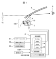
図1は、本発明の一実施例に係る情報表示装置の周辺機器構成を示す概略構成図である。ここではその一例として、自動車のフロントガラス(ウィンドシールドとも呼ばれる)に画像を投射する情報表示装置100について説明する。
<Outline of information display device>
1 is a schematic diagram showing the configuration of peripheral devices of an information display device according to an embodiment of the present invention. As an example, an
図1に示すように、情報表示装置100は、運転者(観視者)の視点(アイポイント)8において自車両の前方に虚像VIを形成するため、被投射部材6(本実施例では、フロントガラスの内面)にて反射された各種情報を虚像VI(Virtual Image)として表示する装置、所謂、ヘッドアップディスプレイ装置である。なお、被投射部材6は、情報が投射される部材であればよく、前述したフロントガラスだけではなく、その他、コンバイナ(図示せず)であってもよい。すなわち情報表示装置100は、運転者の視点8において自車両の前方に虚像を形成して運転者に視認させるものであり、虚像として表示する情報としては、例えば、車両情報や監視カメラやアラウンドビュアーなどのカメラで撮影した前景情報をも含む。
As shown in FIG. 1, the
情報表示装置100は、筐体7の内部に、光源装置10、情報を表示する映像光を投射する映像表示装置4、当該映像表示装置4に表示された映像を被投射部材6に向けて反射させる凹面(自由曲面)ミラー1、当該凹面ミラー1で虚像を形成する際に発生する歪や収差を補正する補正用のレンズ素子2と、補正用のレンズ素子2と映像表示装置4の間には太陽光が凹面ミラー1で集光され映像表示装置4に戻ることを防ぐ光学素子(図示せず)とを備えている。
そして情報表示装置100は、映像表示装置4を制御し光源装置10(バックライト)を駆動する制御装置40を備えている。なお、映像表示装置4と光源装置10などを含む光学部品は、以下に述べる虚像光学系であり、光を反射させる凹面ミラー1を含んでいる。この光学部品において反射した光は、被投射部材6にて反射されて運転者の視点8へと向かう。上記の映像表示装置4としては、バックライトを有する液晶表示素子(LCD)の他に、自発光の蛍光表示管(VFD)などがある。
The
一方、上述した映像表示装置4の代わりに、投射装置によりスクリーンに映像を表示して、前述の凹面ミラー1で虚像とし被投射部材6であるフロントガラス又はコンバイナで反射して運転者の視点8に向かわせてもよい。このようなスクリーンとしては、例えば、マイクロレンズを2次元状に配置したマイクロレンズアレイにより構成してもよい。
On the other hand, instead of the above-mentioned
ここで、虚像の歪みを低減するために凹面ミラー1の形状は、図1に示す上部(相対的に運転者の視点8との距離が短いフロントガラス6の下方で光線が反射する領域)では、拡大率が大きくなるように相対的に曲率半径が小さくなる形状とする。他方、下部(相対的に運転者の視点8との距離が長いフロントガラス6の上方で光線が反射する領域)では、拡大率が小さくなるように相対的に曲率半径が大きくなる形状とするとよい。また、映像表示装置4を凹面ミラー1の光軸に対して傾斜させることで、上述した虚像倍率の違いを補正して発生する歪みそのものを低減することによっても、さらに良好な補正が実現できる。
To reduce distortion of the virtual image, the shape of the
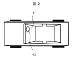
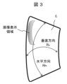
一方、図2、図3に示すように、乗用車のフロントガラス6は、本体垂直方向の曲率半径Rvと水平方向の曲率半径Rhが異なり、一般には、Rh>Rvの関係にある。このため、反射面としてフロントガラス6を捉えると、凹面ミラー1のトロイダル面となる。このため、本実施例の情報表示装置100では、凹面ミラー1の形状はフロントガラス6の形状による虚像倍率を補正するように、すなわち、フロントガラス6の垂直方向と水平方向の曲率半径の違いを補正するように、水平方向と垂直方向で異なる平均曲率半径とすればよい。この時、凹面ミラー1の形状は、光軸に対称な球面または非球面(以下の数式2で示す)形状とすると、光軸からの距離rの関数であり、離れた場所の水平断面と垂直断面形状を個別に制御できない。よって、以下の数式1で示す自由曲面形状として、ミラー面の光軸からの面の座標(x,y)の関数として補正することが好ましい。
On the other hand, as shown in Figs. 2 and 3, the


図1に戻り、さらに映像表示装置4と凹面ミラー1の間に透過型の光学部品として、レンズ素子2を配置し凹面ミラー1への光線の出射方向を制御する。これにより、凹面ミラー1の形状と合わせて歪曲収差の補正を行なうと同時に、前述したフロントガラス6の水平方向の曲率半径と垂直方向の曲率半径の違いによって生じる非点収差を含めた虚像の収差補正を実現する。
Returning to FIG. 1, a
また、収差補正能力をさらに高めるために、上述したレンズ素子2を複数枚のレンズとしてもよい。又は、レンズ素子2の代わりに曲面(自由曲面)ミラーを配置し、光路の折り返しと同時に凹面ミラー1への光線の入射位置を制御することで、歪曲収差を低減することもできる。さらには、収差補正能力を向上させるために最適設計された光学素子を凹面ミラー1と映像表示装置4の間に設けてもよい。また、上述したレンズ素子2の光軸方向の厚さを変化させることで凹面ミラー1と映像表示装置4の光学的な距離を変え、本来の収差補正の他に、虚像の表示位置を遠方から近接位置まで連続的に変化させることもできる。
In order to further improve the aberration correction capability, the
その他、映像表示装置4を凹面ミラー1の光軸法線に対して傾けて配置することで、虚像の上下方向の倍率の違いを補正してもよい。さらに、凹面ミラー1と映像表示装置4の間に、フロントガラス6を通過して凹面ミラー1で集光される太陽光のうち可視光領域のP偏波と紫外線領域と赤外線領域の光を反射又は吸収する光学素子(ここでは図示せず)を設けて、映像表示装置4に戻る光量を軽減することも可能である。
In addition, the
一方、情報表示装置100の画質を低下させる要因として、映像表示装置4から凹面ミラー1に向かって出射する映像光線が、途中に配置されたレンズ素子2の表面で反射して映像表示装置4に戻り、再度反射して本来の映像光に重畳されて、画質を低下させることが知られている。このため本実施例では、レンズ素子2の表面に反射防止膜を成膜して反射を抑えるようにした。さらには、レンズ素子2の映像光入射面と出射面のいずれか一方、若しくは両方のレンズ面形状を、上述した反射光が映像表示装置4の一部分に集光しないような形状(例えば、映像表示装置4に凹面を向けた形状)となるよう、その面形状に制約を持たせている。
On the other hand, it is known that a factor that reduces the image quality of the
さらに、本願発明者等は、レンズ素子2の表面に設ける反射防止膜の特性について検討した。この結果、視感度が最も高い緑色波長領域の反射率を0.2%以下に、赤色波長領域の反射率を0.6%以下に、青色波長領域の反射率を1.0%以下に抑えることで、太陽光が光学素子の表面で反射しても虚像の画質に影響を与えることが無いことを実験により確認した。
The inventors of the present application further investigated the characteristics of the anti-reflection film provided on the surface of the
また映像表示装置4として、上述したレンズ素子2からの反射光を吸収させるために、液晶パネルに近接して配置された第一の偏光板に加えて、第二の偏光板を液晶パネルと分離して配置する。そして、後述する特定方向の偏波光を発生させる本実施例の光源装置を用いることで、通常の液晶映像表示素子に付随する2枚の偏光板の場合と比較し、偏光度を10倍程度高めることができコントラスト性能を大幅に向上できる。さらに、フロントガラス6を通過した太陽光が凹面ミラー1で集光されて液晶パネルに入射する際に、第一、第二の偏光板にて吸収又は反射してその光量を軽減することで、液晶パネルの信頼性を向上させることができる。
In addition to the first polarizing plate arranged close to the liquid crystal panel, the
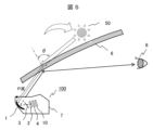
一方、図4に示すように、上述したレンズ素子2と凹面ミラー1の間に、P偏波成分を反射させる機能を有する光学素子3(光学手段とも呼ぶ)を配置する。光学素子3は、凹面ミラー1と映像表示装置4により成立する光軸に対して傾けて配置する。これにより、フロントガラス6から入射した太陽光のP偏波成分を反射して凹面ミラー1から外れた位置に集光させることで、運転者のアイポイント8に反射光が戻ることがなく、自動車の運転に支障をきたすことがない。
On the other hand, as shown in FIG. 4, an optical element 3 (also called optical means) having the function of reflecting the P-polarized component is placed between the
映像表示装置4は、特定の偏波のみが得られる光源からの光を、液晶表示素子により映像信号に合わせて輝度変調するので、この結果得られる映像光はS偏光である。前述した光学素子3(反射型偏光板)は、S偏光の映像光を透過し偏光度を向上させる作用もあることから、運転者が観視する映像のコントラスト性能が向上するという利点もあることが判明した。また、映像光のうち光学素子2の端面で全反射した光は、S偏光からP偏光に変化するため、前述した光学素子3で反射され運転者が観視する映像に悪影響を与えることがない。
The
次に、映像表示装置4として、上述したレンズ素子2からの反射光を吸収させるために液晶パネルに近接して配置された第一の偏光板に加えて、第二の偏光板を液晶パネルと分離して配置すれば、画質の低下を軽減できる。また、液晶パネルのバックライトを、液晶パネルに入射する光の入射方向を映像光が凹面ミラー1の入射瞳に効率良く入射するように制御する。この時、液晶パネルに入射する光束の発散角を小さくすれば、効率良く運転者のアイポイントに映像光を向けることができるばかりでなく、コントラストの高い視認性の良い映像を得ることが可能となる。映像の発散角に対するコントラスト性能は水平方向の方が顕著で、±20度以内であれば優れた特性が得られる。さらにコントラスト性能を向上させるためには、±10度以内の光束を利用するとよい。
Next, in the
一方、光源装置10としては、製品寿命が長い固体光源を採用することが好ましい。特に、周囲温度の変動に対する光出力変化が少ない発光ダイオード(LED:Light Emitting Diode)と、光の発散角を低減する光学手段を設けた偏光ビームスプリッタ(PBS:Polarizing Beam Splitter)を用いて偏光変換を行なうことが好ましい。
On the other hand, it is preferable to use a solid-state light source with a long product life as the
液晶パネルのバックライト側(光入射面)とレンズ素子2側(光出射面)には、ここでは図示しない偏光板が配置されており、これにより、映像光のコントラスト比を高めている。バックライト側(光入射面)に設ける偏光板には、偏光度が高いヨウ素系のものを採用することで、高いコントラスト比が得られる。一方、レンズ素子2側(光出射面)には染料系の偏光板を用いることで、外光が入射した場合や環境温度が高い場合でも、高い信頼性を得ることが可能となる。
Polarizing plates (not shown here) are arranged on the backlight side (light entrance surface) and the
映像表示装置4として液晶パネルを用いる場合、特に、運転者が偏光サングラスを着用している場合には、特定の偏波が遮蔽されて映像が見えないという不具合が発生する。これを防ぐために、液晶パネルのレンズ素子2側に配置した偏光板の光学素子側にλ/4板を配置し、もって、特定の偏光方向に揃った映像光を円偏光に変換するか、偏光サングラスの偏光方向と異なる偏光軸とすることが好ましい。
When using a liquid crystal panel as the
図1に戻り、映像投射以外の部分について説明する。制御装置40は、ナビゲーションシステム61から、自車両が走行している現在位置に対応する道路の制限速度や車線数、ナビゲーションシステム61に設定された自車両の移動予定経路などの各種の情報を、前景情報(すなわち、上記虚像により自車両の前方に表示する情報)として取得する。
Returning to FIG. 1, we will explain the parts other than image projection. The
運転支援ECU(Electronic Control Unit)62は、周辺監視装置63での監視の結果として検出された障害物に従って、駆動系や制御系を制御する運転支援制御の装置である。運転支援制御としては、例えば、クルーズコントロール、アダプティブクルーズコントロール、プリクラッシュセーフティ、レーンキーピングアシストなどの周知技術を含む。
The driving assistance ECU (Electronic Control Unit) 62 is a driving assistance control device that controls the drive system and control system according to obstacles detected as a result of monitoring by the
周辺監視装置63は、自車両の周辺の状況を監視する装置である。一例としては、自車両の周辺を撮影した画像に基づいて自車両の周辺に存在する物体を検出するカメラや、探査波を送受信した結果に基づいて自車両の周辺に存在する物体を検出する探査装置などである。
The
制御装置40は、このような運転支援ECU62からの情報(例えば、先行車両までの距離及び先行車両の方位、障害物や標識が存在する位置など)を前景情報として取得する。さらに制御装置40には、イグニッション(IG)信号及び自車状態情報が入力される。制御装置40は、イグニッション信号が入力されると起動する。自車状態情報とは、各種センサにより取得される車両情報であり、例えば、内燃機関の燃料の残量や冷却水の温度など、予め規定された異常状態となったことを表す警告情報を含んでいる。また、方向指示器の操作結果や自車両の走行速度、さらには、シフトポジション情報なども含まれている。以上が、本実施例の情報表示装置100を含むシステム全体の構成である。
The
<太陽光の装置内への侵入とその抑制原理>
次に、車両の運転席における太陽光の情報表示装置内への侵入について説明する。
図4は、車両の運転席近傍の状態を示している。情報表示装置100は、車体を構成するボンネット44と天井板45との間に取り付けられたフロントガラス6の下方において、例えば、速度計等の計器類を含むダッシュボード42の裏側(後方のボンネット側)に配置されている。また、この図では、車両のハンドル43や、運転者の視点8と共に、車両の上方には昼間の太陽50を示している。また図5は、図4の状態において、特に太陽50とフロントガラス6と運転者の視点8との関係を示している。
<How sunlight penetrates into the device and how it is suppressed>
Next, the intrusion of sunlight into the information display device at the driver's seat of the vehicle will be described.
Fig. 4 shows the state near the driver's seat of a vehicle. The
図4及び図5において、情報表示装置100から出射される映像光は、実線の矢印で示すように、上記フロントガラス6又はコンバイナ(図示せず)において反射されて観視者の視点8に入射する。
In Figures 4 and 5, the image light emitted from the
一方、太陽50からの強い光は、白抜きの矢印で示すように、車両のフロントガラス6に対して入射角θで入射し、その一部がフロントガラス6により反射された後、残りの光は、情報表示装置100の上部に設けられた開口部41を通って当該装置の内部に侵入する。ここに太陽光などの自然光は、P偏光とS偏光が混ざった状態で存在する。この時、特に入射角θが50度以上では、太陽光のS偏光成分(S波)の多くはフロントガラス6上で反射される。その結果、情報表示装置100内に侵入する太陽光の多くはP偏光成分(P波)となる。その理由は、ガラスの反射率が、図6に示すような入射角依存性を示すからである。つまり、フロントガラス6への入射角θが50度を超える領域では、ガラス面上での反射率はS偏光とP偏光とで異なり、S偏光がP偏光よりも大きいからである。
On the other hand, as shown by the white arrow, strong light from the
本実施例は、上述した本願発明者等による知見に基づいており、フロントガラス6を通して侵入する太陽光の多くはP偏光成分であることを考慮している。すなわち、情報表示装置100内に侵入する太陽光を含む外光を抑制するためには、特に、P波成分の低減が有効であること、加えて、情報表示装置100から投射される映像光としては、S波成分を利用することが効果的であることに基づいている。
This embodiment is based on the findings of the inventors of the present application described above, and takes into consideration that most of the sunlight that enters through the
<情報表示装置の光学系の具体的な実施例>
図7は、情報表示装置100を構成する光学系のレンズデータの具体例を示す。レンズデータでは、曲率半径は曲率半径の中心位置が進行方向にある場合を正の符号で表し、面間距離は、各面の頂点位置から次の面の頂点位置までの光軸上の距離を表している。なお、反射光学系においては、面間距離が負の値となる箇所では曲率半径の符号は逆になる。
<Specific Examples of Optical Systems of Information Display Devices>
7 shows a specific example of lens data of the optical system constituting the
偏心はX軸方向・Y軸方向・Z軸方向それぞれの値であり、倒れはX軸回りの回転・Y軸回りの回転・Z軸回りの回転であり、偏心・倒れは、該当の面で偏心と倒れの順に作用し、「普通偏心」では、偏心・倒れが作用した新しい座標系上での面間距離の位置に次の面が配置される。デセンタ・アンド・リターンの偏心及び倒れは、その面でのみ作用し、次の面に影響しない。なお、X軸回りの回転はX軸の正方向から見て時計回りが正、Y軸回りの回転はY軸の正方向から見て時計回りが正、Z軸回りの回転はZ軸の正方向から見て反時計回りが正である。 Eccentricity is the value in the X-axis, Y-axis, and Z-axis directions, while tilt is the rotation around the X-axis, Y-axis, and Z-axis. Eccentricity and tilt act on the relevant surface in that order, and with "normal eccentricity," the next surface is positioned at the inter-surface distance position in the new coordinate system where the eccentricity and tilt acted. The eccentricity and tilt of decenter-and-return only act on that surface and do not affect the next surface. Note that rotation around the X-axis is positive when viewed clockwise when viewed from the positive direction of the X-axis, rotation around the Y-axis is positive when viewed from the positive direction of the Y-axis, and rotation around the Z-axis is positive when viewed counterclockwise when viewed from the positive direction of the Z-axis.
硝材名「50.30」は屈折率1.50でアッベ数が30の材料を、硝材名「52.649」は屈折率1.52でアッベ数が60の材料を表す。本実施例においては、凹面ミラーと折返しミラーを自由曲面形状とすることで、テレセントリック性を確保した上で、後述するように良好な歪性能とスポット図を実現している。 The glass material name "50.30" indicates a material with a refractive index of 1.50 and an Abbe number of 30, and the glass material name "52.649" indicates a material with a refractive index of 1.52 and an Abbe number of 60. In this embodiment, the concave mirror and the folding mirror are made to have a free-form shape, ensuring telecentricity and achieving good distortion performance and spot diagrams, as described below.
図8は、図7のレンズデータの中の、ミラー面に対する自由曲面係数を表す。ここに自由曲面係数は、数式1により求められる。
Figure 8 shows the free-form surface coefficients for the mirror surface in the lens data of Figure 7. The free-form surface coefficients are calculated using
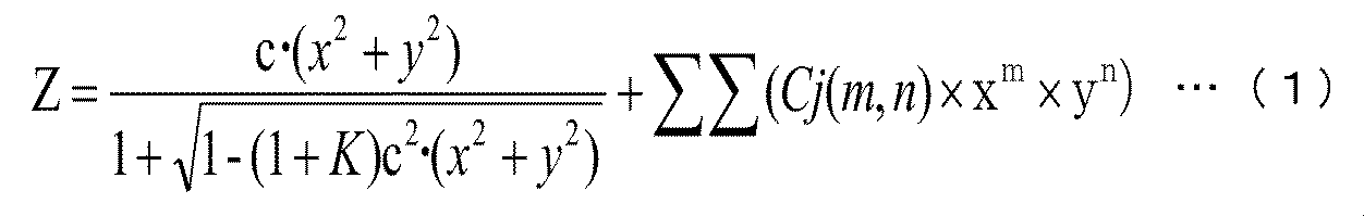
自由曲面係数Cjは、それぞれの光軸(Z軸)に対して回転非対称な形状であり、円錐項の成分とX,Yの多項式の項の成分で定義される形状である。例えば、Xが2次(m=2)でYが3次(n=3)の場合は、j={(2+3)2+2+3×3}/2+1=19であるC19の係数が対応する。また、自由曲面のそれぞれの光軸の位置は、図7のレンズデータでの偏心・倒れの量によって定まる。 The free-form surface coefficients Cj are shapes that are rotationally asymmetric with respect to each optical axis (Z-axis) and are defined by the components of the cone term and the components of the polynomial terms of X and Y. For example, if X is quadratic (m=2) and Y is cubic (n=3), then the corresponding coefficient is C19, where j={(2+3)2+2+3×3}/2+1=19. The position of each optical axis of the free-form surface is determined by the amount of decentering and tilting in the lens data in Figure 7.
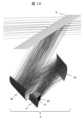
図9は、光学系全体の配置を示す図であり、(a)は水平方向(X軸方向)から、(b)は垂直方向(Y軸方向)から見た図である。さらに図10はその要部拡大図である。図10に示すように、接眼光学系5は液晶表示パネル4側から、偏光ユニット51と、凹レンズ52と、折返しミラー53と、正の屈折力の凹面ミラー54とが、フロントガラス6と並んで配置されることにより構成されている。偏光ユニット51は、特定の条件(入射角度)において装置内に侵入する太陽光のP波成分を抑制し、液晶パネル4を保護するための偏光板を選択する。特に、偏光板が太陽光から受けるダメージを軽減するためには、反射型偏光板を選択するのがよい。本実施例においては、凹面ミラー54と折返しミラー53を自由曲面形状とすることで、テレセントリック性を確保した上で、良好な歪性能と結像性能(スポット像)を実現している。
9 shows the arrangement of the entire optical system, where (a) is a view from the horizontal direction (X-axis direction) and (b) is a view from the vertical direction (Y-axis direction). Furthermore, FIG. 10 is an enlarged view of the main part. As shown in FIG. 10, the eyepiece
以下に、本実施例の接眼光学系の諸元として、アイボックスサイズ、視野角などの値を、水平方向、垂直方向の順に示す。
アイボックスサイズ 130×40mm
液晶表示パネルでの映像光の有効サイズ 68.0×25.2mm
虚像サイズ 3500×943mm
視野角(全画角) 10.0×2.7度
伏角 2.376度
虚像距離 20.0m
The specifications of the eyepiece optical system of this embodiment, such as eyebox size and angle of view, are shown below in the order of horizontal and vertical directions.
Eye box size: 130 x 40 mm
Effective size of image light on LCD panel: 68.0 x 25.2 mm
Virtual image size: 3500 x 943 mm
Field of view (full field of view) 10.0 x 2.7 degrees Dip angle 2.376 degrees Virtual image distance 20.0 m
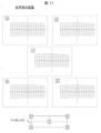
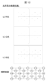
また、本実施例の情報表示装置100の光学性能について説明する。図11は、情報表示装置の歪性能を表す図である。アイボックス内の各位置における歪量を示している。図12は、情報表示装置の結像性能をスポット像で示したものである。視野範囲内の各位置における色別のスポット像を示す。これらの結果に示されるように、良好な歪性能と結像性能(スポット像)を得ることができた。なお、本実施例では、液晶表示パネル4に対して、照明光学系を14度傾けて配置している。従って、本実施例によれば、凹レンズ52と凹面ミラー54を用いた投射光学系により、虚像距離の大きい情報表示装置100を提供できる。
The optical performance of the
<情報表示装置の具体的な実施例>
続いて、上述した知見に基づいて構成した情報表示装置100の、より具体的な光学系の構成について説明する。
<Specific Examples of Information Display Device>
Next, a more specific configuration of the optical system of the
図13は、情報表示装置100の全体構成を拡大して示しており、上述したように、下流側から順に、フロントガラス6を介して虚像を形成する映像光を投射する凹面ミラー1、その際に発生する歪や収差を補正するための補正用のレンズ素子(レンズ群)2、P波成分を抑制する(反射する)ための光学素子3、映像表示装置4、バックライトを構成する光源装置10が設けられている。なお、本構成は、折り返しミラー53(図10を参照)が不要な短い光路の光学系の例を示す。ここに光学素子3は、情報表示装置100の内部に侵入する太陽光のP波成分を抑制するためのもので、レンズ素子2と映像表示装置4の間に反射型偏光板を設けている。これにより、映像表示装置4の液晶パネルの光入出射側両面に設けた偏光板の偏光度に加えて反射型偏光板の偏光度が加わるため、高コントラストな映像を得ることができる。また、この光学素子3(反射型偏光板)は、上述した虚像光学系の光軸に対して傾けて配置されているため、反射光がフロントガラス6を介して運転者の目に入ることはなく、運転の支障にならない。
Figure 13 shows an enlarged view of the overall configuration of the
まず、映像光を投射する凹面ミラー1には、可視光(波長:略400~700nm)を反射すると同時に、情報表示装置にとって不要で装置にダメージを与える光成分を除去する機能を持たせる。例えば、各種の波長スペクトルを含む太陽光から、赤外線(IR)や紫外線(UV)などを除去する機能を持たせる。この時、可視光の反射率を95%以上とすることにより、光利用効率が高い虚像光学系が実現できる。
First, the
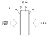
次に図14は、光学素子3としての反射型偏光板の構成を模式的に示す縦断面図である。光学素子3の基板3aには、上述した太陽光のうちで可視光領域の波長の光が基板3aに吸収されないように、透明性が高い材料を用いる。そして、基板3aの表面に反射型偏光板3bを形成する。
Next, FIG. 14 is a vertical cross-sectional view showing a schematic configuration of a reflective polarizing plate as the
反射型偏光板3bを得る方法としては、従来のガラス基板にフォトリソグラフィーの成膜プロセスでアルミパターンを形成する方法(1)がある。他に、近年、ナノインプリントによりアルミパターンを形成することで、(1)に比べて安価な反射型偏光板を得る方法(2)が知られる。(2)の代表としては、例えば、旭化成イーマテリアルズ(株)の反射型偏光フィルムWGF(登録商標)がある。
One method for obtaining the reflective
旭化成イーマテリアルズ(株)の反射型偏光板の製造方法は、同社の技術資料によれば、TACフィルムの表面にナノインプリント製法によりロールtoロールプロセスで紫外線硬化樹脂を印刷により賦形し、その表面(側面を含む)にアルミ膜を成膜することで反射型偏光板を得るものである。この時得られる偏光特性(平行光線透過率とクロス透過率)は、上述した(1)の反射型偏光板と同様に、形成された突起部の高さとピッチにより一義的に決まる。(2)の方法により、安価で価格メリットが大きい、例えば上述した反射型偏光板WGF(登録商標)を適用する場合の課題と解決策について、以下に図面を用いて説明する。 According to the company's technical documentation, Asahi Kasei E-Materials Corporation's manufacturing method for reflective polarizing plates involves printing and shaping ultraviolet-curable resin on the surface of a TAC film using a roll-to-roll process with a nanoimprinting method, and then forming an aluminum film on the surface (including the sides) to obtain a reflective polarizing plate. The polarization characteristics (parallel light transmittance and cross transmittance) obtained at this time are uniquely determined by the height and pitch of the formed protrusions, just like the reflective polarizing plate (1) above. The issues and solutions when applying method (2), which is inexpensive and has great price benefits, for example the reflective polarizing plate WGF (registered trademark) mentioned above, are explained below with reference to the drawings.
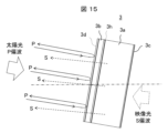
図14、図15、図16は、反射型偏光板の構成を示す断面図である。これらの図に示すように、本実施例では、太陽光が入射する側に反射型偏光板3bを設ける。より具体的には、基板3aに反射型偏光板3bを接着剤又は粘着剤3hにより粘着する(図15参照)。そして、基板3aを含めた反射型偏光板3bの光線透過率を高めるために、反射型偏光板3bの表面及び粘着面の対面にも、増透効果を持つ防湿膜3dとしてSiO(酸化シリコン)を成膜するとよい。但し基板3aがガラス素材の場合には、一般的な反射防止膜を設けるとよい。
Figures 14, 15, and 16 are cross-sectional views showing the structure of a reflective polarizing plate. As shown in these figures, in this embodiment, a reflective
上述した防湿膜3dは、膜厚を波長の1/4相当として反射防止特性を持たせるとさらによい。この時、情報表示装置100の光源として利用するLEDからの出射光は、波長が450nmから650nmの範囲がほとんどであるから、中心波長550nmに対する反射防止を兼ねた防湿膜3dの膜厚を、130nmから145nmの間に設定するとよい。一方、反射型偏光板3bを設けた基板3aの対面には、反射防止膜3cを成膜することで不要光の発生を低減できる。
It is even better if the moisture-
図15に示すように、映像光は、反射型偏光板3bの貼付面の反対側から入射するように光路中に配置するとよい。その理由は、前述したように車内に入射する太陽光のほとんどがP偏波であるため、反射型偏光板3bで反射した反射光の光路は次のようになる。(1)光路を正規に戻り、フロントガラス6で反射して運転者側に戻る正規反射光となる。(2)その他として、より斜め方向から入射した太陽光は、反射型偏光板3bの側面で反射して迷光となる。この光を軽減するために、基板3aの太陽光入射面には反射防止膜3cを設けることで、反射型偏光板3bの入出射面で発生する反射光が軽減され、グレア発生が抑えられることで画質低下が軽減される。また反射型偏光板3bは以下に述べる構造のため、基板3aに対し太陽光が入射する側に設けるのがよい。
As shown in FIG. 15, the image light should be arranged in the optical path so that it is incident from the opposite side to the surface to which the reflective
図16は、本実施例の反射型偏光板3の具体的構造を示す断面図である。ガラス基板3aの片面に、反射型偏光板3bを接着剤又は粘着剤3hにより粘着固定する。反射型偏光板3bには、例えば旭化成イーマテリアルズ(株)から販売されている反射型偏光板WGF(登録商標)を用いる。ここで反射型偏光板WGF(登録商標)の製造方法は、その技術資料によれば、基材のTAC(トリアセチルセルロース)フィルム3fの表面に、ナノインプリント製法によりロールtoロールプロセスで紫外線硬化樹脂3jを印刷により賦形し、その表面(側面を含む)にアルミ膜3kを成膜することで反射型偏光板3bを得ていると記載される。
Figure 16 is a cross-sectional view showing the specific structure of the
一般的にこのTACフィルムは、太陽光に含まれる紫外線により黄変し透過率が大幅に低下するという信頼性上の課題がある。そこで本願発明者等は、上記反射型偏光板3bの構成において、図16に示すように、反射型偏光板3bの全面をアクリル系紫外線硬化樹脂3jで覆い、反射型偏光板3bを貼り付けた面を太陽光入射側に向ける配置とした。すなわち、TACフィルム3fを覆うようにアクリル系紫外線硬化型樹脂3jを配置しているので、これにより太陽光の紫外線成分を吸収し、TACフィルム3fの紫外線成分による劣化を防止できる。
Generally, this TAC film has a reliability issue in that it yellows due to the ultraviolet rays contained in sunlight and its transmittance drops significantly. Therefore, the inventors of the present application have configured the reflective
また本願発明者等は、図16における防湿膜3dを成膜する条件として、成膜後の安定性を考慮し、成膜時の炉内温度に着目して最適条件を見出した。防湿膜3dの成膜工程では、反射型偏光板3bの基材であるTAC(トリアセチルセルロース)フィルム3fの線膨張率と、アクリル系紫外線硬化樹脂3jの線膨張率の差によって生じる応力によって、TACフィルム3fからアクリル系紫外線硬化樹脂3jが剥がれることが懸念される。これを防ぐため、低温での蒸着又はスパッタにより、防湿膜3dとしてSiO(酸化シリコン)を表面に成膜するようにした。この時の蒸着装置又はスパッタ装置の炉内温度は、基板付近では70℃以下が望ましく、50℃以下で蒸着又はスパッタすれば、反射型偏光板3bの構成を変化させることがなくより安定に性能を維持できる。
The inventors of the present application also found the optimum conditions for forming the moisture-
この時成膜する防湿膜3dの膜厚は、前述したように透過する光に含まれる波長の1/4相当として、反射防止特性を持たせるとさらによい。同様に、反射型偏光板3bを貼付けた基板3aの対面には反射防止膜3cを成膜することで、不要光の発生を低減できる。また、上述したように、反射型偏光板3bを設けた面に対向する面には反射防止膜3cを複数層設け増透効果を得るようにすれば、界面反射が低減され表示された映像の画質が損なわれることがない。
The thickness of the moisture-
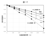
図17は、防湿膜3dの効果を示す図である。上述した防湿膜3dの水分に対するバリア性の評価サンプルを、85℃85%RHの高温・高湿環境下に放置し、透過率の初期値に対する変化を相対値として評価した。その際、防湿膜3dの膜厚をパラメータとして評価している。その結果は、保護膜なしに比べ防湿膜3dの厚さを増やしてゆくほど透過率の低下(劣化)が少なく、保護膜がないサンプル(反射型偏光板単品)に対して、膜厚20nmでは1500時間経過時点での透過率劣化を6%程度軽減した。さらに、増透効果が得られる140nm前後の膜厚では、初期透過率が1.5%程度改善し、1500時間経過後の相対値劣化は4%に低減できた(図示せず)。一方、防湿膜3dの膜厚が500nmを超え、雰囲気が90℃を超える高温中に長期に置かれた場合には、防湿膜3dとTACフィルム3f、紫外線硬化樹脂3jの線膨張率の違いにより、3つの部材間で発生する応力が大きくなり形状を維持できなくなった。
Figure 17 is a diagram showing the effect of the moisture-
なお、上述の反射型偏光板3bの基板3aには、ガラス基板の他では透明性が高いものを選択する。また、上述した反射型偏光板3bを、プラスチック製の非球面レンズや自由曲面レンズに設けてもよい。この時の透明度が高い材料としては、(1)日本ゼオン株式会社のZEONEX(登録商標)、(2)ポリカーボネイト、(3)アクリル等がある。(1)のZEONEX(登録商標)は、吸水率がほぼ0%で熱変形温度が高く最適であるが価格が高い。(3)のアクリルは、成形性が最も高く、安価であるが、使用する際には吸湿を抑えるため防湿膜を設けることが必要となる。
For the
さらに、情報表示装置100の上部に形成される開口部41(図13参照)に、上述した赤外光や紫外光の少なくとも一方を抑制/除去する機能を備える透光板(図示せず)を設けてもよい。かかる透光板は、赤外光や紫外光の抑制機能に加え、外部の塵が情報表示装置100内部に侵入することを防止する機能をも備えることができる。
Furthermore, a light-transmitting plate (not shown) having a function of suppressing/removing at least one of the infrared light and ultraviolet light described above may be provided in the opening 41 (see FIG. 13) formed in the upper part of the
このように、開口部41から情報表示装置100の内部に侵入する多数のスペクトル成分を含む太陽光のうち、当該情報表示装置100では不要な成分を除去し、主に可視光成分を選択的に取り出すことが可能となる。図18には、太陽光の分光放射照度の特性を示す。
In this way, the
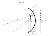
次に図29は、情報表示装置において凹面ミラーで虚像が得られる原理を説明する図である。凹面ミラー1’の光軸上の点Oに対して、焦点F(焦点距離f)の内側に物点ABを配置することで、凹面ミラー1’による虚像を得ることができる。ここでは説明の都合上、凹面ミラー1’を同じ正の屈折力を持つ凸レンズとみなし、物点と凸レンズ(ここでは説明の都合上、凹面ミラーで表記)と発生する虚像の関係を示している。 Next, Figure 29 is a diagram explaining the principle by which a virtual image is obtained with a concave mirror in an information display device. A virtual image can be obtained with the concave mirror 1' by placing an object point AB inside the focal point F (focal length f) with respect to point O on the optical axis of the concave mirror 1'. For convenience of explanation, the concave mirror 1' is regarded as a convex lens with the same positive refractive power, and the relationship between the object point, the convex lens (represented as a concave mirror here for convenience of explanation), and the virtual image that is generated is shown.
情報表示装置で発生する虚像を運転者が観視した場合に、フロントガラス6上部で反射して運転者に見える虚像(遠方の風景に重ねたい像)と、フロントガラス6下部で反射して運転者に見える虚像(近傍の風景に重ねたい像)とのフォーカス性能を同時に確保することが望ましい。そのため、映像表示装置(図29ではABに対応、本実施例では液晶パネル)と凹面(自由曲面)ミラー1’の光軸LL’に対して映像表示装置(AB)を傾けるとよい。これは、液晶パネルと凹面(自由曲面)ミラー1’で生じる虚像の倍率M=b/aを同時に満足するためでもある。
When the driver views a virtual image generated by the information display device, it is desirable to simultaneously ensure the focusing performance of the virtual image reflected by the upper part of the
以上の情報表示装置100の光学構成によれば、フロントガラス6を介して装置の内部に侵入する太陽光のうち、そのP波成分(p偏光波)を上述した光学素子3により有効に低減することができる。つまり、光学素子3により、上部の開口部41を通って情報表示装置100の内部に侵入した太陽光が、当該内部に配置された映像表示装置4や周辺の偏光板等に対して炭化等の悪影響を及ぼすことを防止する。これにより、液晶表示素子や偏光板へのダメージを軽減し、太陽光による情報表示装置100の性能の低下を抑制することができる。また、光学素子3に防湿膜を設けることにより、水分や、排気ガス等に含まれる硫化物等による映像表示装置4や周辺の偏光板等への悪影響を低減することができる。
According to the optical configuration of the
<映像表示装置の光源装置>
上述したように、情報表示装置100の光学系では、フロントガラス6を介して外部から装置内に入射する太陽光は、上記光学素子3により低減される。これと同時に、自車両の前方に表示する各種の映像情報の虚像を生成するための映像光は、前記の図4や図5に実線の矢印で示すように、映像表示装置4から出射され、レンズ素子2や凹面ミラー1を介して、フロントガラス6に到達する。その際にも、映像光は上記光学素子3を通ることとなるが、既述のように、この映像光にはS波成分(s偏光波)が利用される。
<Light source device for image display device>
As described above, in the optical system of the
そこで、以下には、S波成分の映像光を生成するための映像表示装置4とその光源装置10について詳細に述べる。
図19は、映像表示装置4と光源装置10の配置を示す構成図である。ここには、映像表示装置4である液晶表示素子と共に、その下方には、その光源を構成する光源装置10を展開斜視図により示している。
Therefore, the
19 is a configuration diagram showing the arrangement of the
光源装置10は、例えばプラスチックなどにより形成され、その内部に、後述するLED、コリメータ、合成拡散ブロック、導光体等を収納してなる光源装置ケース101から構成されている。その上面には、映像表示装置4である液晶表示素子が取り付けられている。また、光源装置ケース101の1つの側面には、半導体光源であるLED素子やその制御回路を実装したLED基板102が取り付けられていると共に、当該LED基板102の外側面には、上記LED素子および制御回路で発生する熱を冷却するためのヒートシンク103が取り付けられている。
The
他方、光源装置ケース101の上面に取り付けられた映像表示装置4である液晶表示素子は、液晶表示パネルフレーム401と、当該フレームに取り付けられた液晶表示パネル402と、さらに、当該パネルに電気的に接続されたフレキシブル配線基板(FPC:Flexible Printed Circuits)403とから構成されている。すなわち、液晶表示パネル402は、後述する通り、固体光源であるLED素子と共に、電子装置を構成する制御回路(ここでは図示せず)からの制御信号によって、表示される映像が生成され、制御される。
On the other hand, the liquid crystal display element, which is the
続いて、光源装置10の内部構成、すなわち、光源装置ケース101内に収納されている光学系について、以下に図面を参照しながら詳細に説明する。
Next, the internal structure of the
図20は、光源装置10の構成を示す概略構成図である。また図21は、光源装置10内の光の伝播を示す断面図である。また図22は、光源装置10内の偏光変換素子を示す概略構成図である。これらの例では、光源を構成する複数(本例では2個)のLED14a、14bが示しており、これらはLEDコリメータ15に対して所定の位置に取り付けられている。LEDコリメータ15は、各々、例えば、アクリル等の透光性の樹脂により形成されている。このLEDコリメータ15は、図21にも示すように、略放物断面を回転して得られる円錐凸形状の外周面156を有すると共に、その頂部では、その中央部に凸部(すなわち、凸レンズ面)157を形成した凹部153を有する。また、その平面部の中央部には、外側に突出した凸レンズ面(あるいは、内側に凹んだ凹レンズ面でもよい)154を有している。なお、LEDコリメータ15の円錐形状の外周面(放物面)156は、LED14a,14bから周辺方向に出射する光をその内部で全反射することが可能な角度範囲内に設定され、あるいは反射面が形成されている。
Figure 20 is a schematic diagram showing the configuration of the
他方、LED14a、14bは、その回路基板である、所謂、LED基板102の表面上の所定の位置にそれぞれ配置されている。このLED基板102は、LEDコリメータ15に対して、その表面上のLED14a又は14bが、それぞれ、その凹部153の中央部に位置するように配置されて固定される。
On the other hand, the
かかる構成によれば、上述したLEDコリメータ15によって、LED14aまたは14bから放射される光のうち、特に、その中央部分から上方(図の右方向)に向かって放射される光は、LEDコリメータ15の外形を形成する2つの凸レンズ面157、154により集光されて平行光となる。また、その他の部分から周辺方向に向かって出射される光は、LEDコリメータ15の円錐形状の外周面を形成する放物面によって反射され、同様に、集光されて平行光となる。換言すれば、その中央部に凸レンズを構成すると共に、その周辺部に放物面を形成したLEDコリメータ15によれば、LED14aまたは14bにより発生された光のほぼ全てを平行光として取り出すことが可能となり、発生した光の利用効率を向上することが可能となる。
With this configuration, the light emitted from the
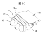
図20、図22に示すように、LEDコリメータ15の光の出射側には、偏光変換素子21が設けられている。この偏光変換素子21は、断面が平行四辺形である柱状(以下、平行四辺形柱)の透光性部材と、断面が三角形である柱状(以下、三角形柱)の透光性部材とを組み合わせ、LEDコリメータ15からの平行光の光軸に対して直交する面に平行に、複数、アレイ状に配列して構成されている。さらに、これらアレイ状に配列された隣接する透光性部材間の界面には、交互に、偏光ビームスプリッタ(PBS)膜211と反射膜212とが設けられており、また、偏光変換素子21へ入射してPBS膜211を透過した光が出射する出射面には、1/2λ位相板213が備えられている。
As shown in Figures 20 and 22, a
この偏光変換素子21の出射面には、さらに、図20にも示す矩形状の合成拡散ブロック16が設けられている。すなわち、LED14aまたは14bから出射された光は、LEDコリメータ15の働きにより平行光となって合成拡散ブロック16へ入射する。図23は、合成拡散ブロック16の構成を示す概略図である。合成拡散ブロック16に入射した光は、出射側のテクスチャー161により拡散された後、図20に示す導光体17に到る。
The exit surface of this
図20において、合成拡散ブロック16の出射面側には、第1の拡散板18aを介して、断面略三角形の角柱状の導光体17が設けられており、その上面には、第2の拡散板18bが取り付けられている。これにより、上記LEDコリメータ15の水平光は、当該導光体17の働きにより図の上方に反射されて、液晶表示素子の入射面に導かれる。その際、上記第1及び第2の拡散板18a、18bによって、入射光の強度が均一化される。
In FIG. 20, a prismatic
図24は、導光体17の詳細な構成を示す図である。このうち、(a)は導光体17の全体を示す斜視図を、(b)はその断面図、(c)及び(d)は、断面の詳細を示す一部拡大図である。
Figure 24 shows the detailed configuration of the
導光体17は、例えば、アクリル等の透光性の樹脂により断面が略三角形(図24(b)参照)の棒状に形成された部材である。そして、図24(a)に示すように、第1の拡散板18aを介して合成拡散ブロック16(図20参照)の出射面に対向する導光体光入射部(面)171と、斜面を形成する導光体光反射部(面)172と、第2の拡散板18bを介して液晶表示素子の液晶表示パネル402(図19参照)と対向する導光体光出射部(面)173とを備えている。
The
また、図24(c)及び(d)の一部拡大図に示すように、導光体17の導光体光反射部(面)172には、多数の反射面172aと連接面172bとが交互に鋸歯状に形成されている。そして、反射面172a(図では右上がりの線分)は、図において一点鎖線で示す水平面に対してαn(n:自然数であり、本例では1~130)を形成しており、その一例として、ここでは、αnを43度以下(但し、0度以上)に設定している。
As shown in the partially enlarged views of Figures 24(c) and (d), the light guide light reflecting portion (surface) 172 of the
他方、連接面172b(図では右下がりの線分)は、反射面に対してβn(n:自然数であり、本例では1~130)を形成している。すなわち、反射部の連接面172bは、入射光に対して、後述する散乱体の半値角の範囲で陰になる角度に傾斜されている。後述するが、αnは反射面仰角を、βnは反射面と連接面との相対角度である。その一例として相対角度βnは90度以上(但し、180度以下)に設定し、本例では全て等しくしている(β1=β2=β3=・・・=β130)。
On the other hand, the connecting
図25および図26は、導光体17の導光体光反射部(面)172の拡大図である。ここでは説明のために、導光体17の大きさに対する反射面172aと連接面172bの大きさを相対的に大きくして示す。まず図26(b)に示すように、導光体17の導光体入射部(面)171では、主たる光線が、反射面172aに対して入射角が大きくなる方向にδだけ偏向されている。すなわち、導光体入射部(面)171は、光源側に傾斜した湾曲の凸形状に形成されている。これによれば、合成拡散ブロック16の出射面からの平行光は、第1の拡散板18aを介して拡散されて入射し、図からも明らかなように、導光体入射部(面)171により上方に僅かに屈曲(偏向)しながら導光体光反射部(面)172に達する。
25 and 26 are enlarged views of the light guide light reflecting portion (surface) 172 of the
導光体光反射部(面)172には、多数の反射面172aと連接面172bとが交互に鋸歯状に形成されている。第1の拡散板18aからの拡散光は、各々の反射面172a上で全反射されて上方に向かい、さらには、導光体光出射部(面)173や第2の拡散板18b(図25に示す)を介して、平行な拡散光として液晶表示素子50の液晶表示パネル402へ入射する。そのため、反射面仰角αnは、各々の反射面172aが前記拡散光に対して臨界角以上の角度となるように設定されている。他方、反射面172aと連接面172bとの相対角度βnは、上述したように一定の角度、より好ましくは90度以上の角度に設定されている。
The light guide light reflecting portion (surface) 172 has a number of reflecting
上述した構成により、各反射面172aが前記拡散光に対して常に臨界角以上の角度となっているので、反射部172に金属等の反射膜を形成しなくても全反射が可能となり、低コストの光源装置10を実現できる。
With the above-mentioned configuration, each reflecting
また、反射面仰角αnは、導光体光反射部(面)172の下部から上部に移動するに従って、わずかずつ増加する値としている。これは、液晶表示素子の液晶表示パネル402を透過した光はある程度の発散角を有しているため、特に液晶表示パネル402の周辺部を透過した光の一部が、下流に配置されたミラーの周縁でけられ、いわゆる周辺減光が発生するのを防止するためである。すなわち、図25の光線30に示すように、周辺部の光線をやや中心軸方向に偏向させた構成とすることで、周辺減光を防止している。
The reflecting surface elevation angle αn is set to a value that increases slightly as one moves from the bottom to the top of the light guide light reflecting portion (surface) 172. This is because the light that has passed through the liquid
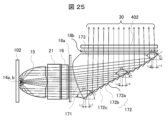
また、図25において、Lr1、Lr2、Lr3・・・は反射面172aの水平面に対する投影長さを、Lc1、Lc2、Lc3・・・は連接面172bの水平面に対する投影長さを表しており、反射面172aと連接面172bとの投影長さの比率Lr/Lcを、場所により変更可能な構成とした。導光体17に入射する主たる光線30の強度分布は、必ずしも液晶表示パネル入射面で望まれる強度分布と一致しない。そこで、反射面172aと連接面172bとの比率Lr/Lcにより、強度分布を調整する構成を採用した。なお、この比率を高めるほど、その部分の反射光の平均的な強度を高めることができる。一般的に、導光体17に入射する光線30は中央部が強くなりがちである。それを補正するのに、前記比率Lr/Lcを場所により異なるようにし、特に中央部において小さくなるようにした。前記比率Lr/Lcが場所により異なる構成、および前述した反射面仰角αnが場所により異なる構成としたため、反射部172の概形状を表す包絡線172cは、図25に示すように曲線形状を示す。
In addition, in FIG. 25, Lr1, Lr2, Lr3, etc. represent the projected length of the reflecting
さらに、反射面172aと連接面172bの投影長さLr,Lcに関し、両者の和Lr+Lcを各位置において一定の値とし、かつ0.6mm以下となるようにした。すなわち、Lr1+Lc1=Lr2+Lc2=・・・≦0.6mmの関係とした。かかる構成とすることで、導光体17の光出射面173から見た反射面の繰り返しピッチを同一とすることができる。また、そのピッチは0.6mm以下であることから、拡散板18a、18bの作用、効果と相まって、液晶表示パネル402越しで見た場合、個々の出射面が分離せず、連続面として見えることになる。よって、液晶表示パネル402越しの空間輝度の均一化が図れ、もって、表示特性が向上する。すなわち本構成により、液晶表示パネル402上での入射光強度分布を均一化することが可能となる。なお、Lr+Lcの値を小さくしすぎると加工時間が増大するばかりではなく、各反射面172aを精度良く加工するのが困難となるので、Lr+Lcの下限値は実用的には0.2mmが望ましい。
Furthermore, the sum Lr+Lc of the projection lengths Lr and Lc of the reflecting
上述した導光体17の導光体光反射部(面)172の形状によれば、主たる光の全反射条件を満たすことができ、反射部172にアルミ等の反射膜を設ける必要がなく、光を効率的に反射することが可能となり、製造コストの上昇を伴うアルミ薄膜の蒸着作業なども必要なく、より低コストで、明るいS波成分(s偏光波)の光源が実現できる。また、各相対角βについては、連接面172bが、合成散乱ブロック16および拡散板18aで拡散された光線30に対して陰になるような角度に設定した。これにより、連接面172bへの不要な光の入射を抑制することで、不要な光の反射を低減でき、特性が良好な光源装置を実現できる。
The shape of the light guide light reflecting portion (surface) 172 of the
また、上述した導光体17によれば、反射面仰角αnを適宜設定することにより、光軸方向における光出射面173の長さを自由に変更することができる。よって、導光体入射部(面)171に対する光出射面173の大きさ(面サイズ)を、液晶表示パネル402などの装置に適合する大きさ(面サイズ)に適宜変更可能な光源装置を実現することができる。また、これにより、光源を構成するLED14a、14bの配置形状に依存せずに、光出射面173を所望の大きさにできることから、所望の大きさの面状の発光源が得られることになる。さらには、光源を構成するLED14a、14bの配置を含む設計における自由度の確保にも繋がり、装置全体の小型化に有利になる。
In addition, according to the
図27は、上述の導光体として偏光変換素子を用いた場合を示す。すなわち、合成拡散ブロック16の後方に配置される導光体17を、通常の透光性の樹脂に代えて、偏光変換素子により構成したもので、導光体17’として示す。導光体17’は、三角形柱の透光性部材211’と平行四辺形柱の透光性部材212’を組み合わせ、それらの境界面にはPBS膜211を形成している。PBS膜211は、LED14から出射してLEDコリメータ15で平行光となった入射光のS偏光波(図中の記号(×)を参照)を反射するが、P偏光波(図中の上下の矢印を参照)を透過する。平行四辺形柱の透光性部材212’の上面には1/2λ位相板213を、またその側面には反射膜212を形成している。
Figure 27 shows a case where a polarization conversion element is used as the light guide. That is, the
この構成によれば、LED14から出射してLEDコリメータ15で平行光となった入射光は、偏光変換素子からなる導光体17’により、S偏光波に偏光されて当該素子の上面から上方に向かって出射される。すなわち、この構成では、通常の透光性の樹脂からなる導光体17を削除でき、装置の大幅な小型化や装置の製造コストの低減が可能となる。
With this configuration, the incident light emitted from the
以上に述べた光源装置10を、映像表示装置4である液晶表示素子の光源装置として利用することで、より少ない発光源(LEDの数量、消費電力)で小型かつ高効率のモジュール化されたS偏光波の光源装置が実現できる。そして、上述した凹面ミラー1や光学素子3により、不要な赤外線(IR)や紫外線(UV)を除去すると共に、映像表示装置4や周辺の偏光板等に対して炭化等の悪影響を及ぼすP波成分(p偏光波)を有効に低減できる。これにより、太陽光によるダメージを軽減し、かつ、S波成分(s偏光波)の利用により優れた情報表示が可能な情報表示装置100を実現することが可能となる。
By using the
以上に詳述したように、本実施例に係る情報表示装置100によれば、光利用効率やその均一な照明特性をより向上すると同時に、モジュール化されたS偏光波の光源装置を含め、小型かつ低コストで製造することが可能となる。なお、上記の説明では、偏光変換素子21をLEDコリメータ15の後に取り付けるものとして説明したが、本発明はそれに限定されることなく、液晶表示素子に至る光路中に設けることによっても同様の作用・効果が得られる。
As described above in detail, the
<その他の構成>
上述した情報表示装置100によれば、その動作中においては、凹面ミラー1や光学素子3により、太陽光の不要なIR光やUV光及びP偏波光の除去が可能である。しかしながら、例えば、駐車場などに車両を停止してエンジンキーを切った状態では、当該情報表示装置100の表示動作は不要である。そこで、このような状態では、侵入する太陽光を通常の光路から排除する。すなわち、上部の開口部41を通って情報表示装置100の内部に侵入して、映像表示装置4やその前後に配置された偏光板等に至る光路を通らないようにする。
<Other configurations>
According to the above-described
図28は、太陽光が映像表示装置4に到達しないようにした構成例を示す図である。情報表示装置100の各部品を分解した状態で、背面側から見た展開斜視図である。筐体である外装ケース46,47の内部において、凹面ミラー1を回動可能に取り付ける。凹面ミラー1の位置は、電動モータ等により構成される凹面ミラー駆動部48により調整し、侵入する太陽光が映像表示装置4に至らない方向(通常の光路とは異なる方向)に反射するように、予め設定された位置に移動させる。
Figure 28 is a diagram showing an example of a configuration that prevents sunlight from reaching the
すなわち、情報表示装置100を使用しない場合には、太陽光が映像表示装置4に戻らないように凹面ミラー1を所定の角度を回転させることで、凹面ミラー1により集光される太陽光が映像表示装置4に戻ることを防止する。なお、かかる凹面ミラー駆動部48の動作は、前記図1に示した制御装置40が備えるCPU35により、ROM34内に予め格納したソフトウェアを実行することで実現する。
In other words, when the
この構成によれば、侵入する太陽光が問題となる車両の停止状態において、特に、真夏などの強い太陽光の下において、太陽光が情報表示装置100の光学部品である映像表示装置4や周辺の偏光板、さらには、光源装置10等を破損・劣化させてしまう事態を、より確実に防止することが可能となる。
This configuration makes it possible to more reliably prevent sunlight from damaging or deteriorating the optical components of the
以上に述べた本実施例の情報表示装置の特徴をまとめると、次のようになる。凹面ミラーから映像表示装置(液晶パネル)までの虚像光学系において、
(1)昼間の所定条件下においてフロントガラスを通過した太陽光成分(コンバイナ方式ではその後コンバイナも通過)のうちP偏光が凹面ミラーで集光されても、光学系内に設けたP波成分抑制光学手段(素子)である反射型偏光板で反射させ液晶パネルと偏光板に戻らないようにする。
(2)情報表示装置を使用しない場合には、太陽光が映像表示装置に戻らないように凹面ミラーを所定の角度だけ回転させることで、凹面ミラーにより集光される太陽光が映像表示装置に戻ることを防止する。
(3)太陽光の一部が運転者の視点(目)に戻らないようにする光学素子を設けることで、太陽光を含む外光に対する耐性と画質低下を大幅に向上した情報表示装置を提供する。
(4)反射型偏光板と特定偏波の光を供給する光源を併設することで、映像光の偏光度が向上しコントラスト性能が向上する。
(5)反射型偏光板の温度・湿度・硫化物などに対する高い信頼性を得るため、表面に防湿膜(保護膜)を設けて外気の影響による構造物の変化で特性が劣化することを軽減する。
The features of the information display device of this embodiment described above can be summarized as follows: In the virtual image optical system from the concave mirror to the image display device (liquid crystal panel),
(1) Under specified daytime conditions, even if P-polarized sunlight components that pass through the windshield (and then pass through the combiner in the case of the combiner method) are concentrated by the concave mirror, they are reflected by a reflective polarizing plate, which is a P-wave component suppression optical means (element) installed in the optical system, so as not to return to the liquid crystal panel and the polarizing plate.
(2) When the information display device is not in use, the concave mirror is rotated by a predetermined angle to prevent sunlight from returning to the image display device, thereby preventing sunlight concentrated by the concave mirror from returning to the image display device.
(3) By providing an optical element that prevents part of the sunlight from returning to the driver's viewpoint (eyes), an information display device is provided that has significantly improved resistance to external light, including sunlight, and reduced degradation in image quality.
(4) By combining a reflective polarizing plate with a light source that supplies light of a specific polarization, the degree of polarization of the image light is improved, thereby improving contrast performance.
(5) In order to ensure high reliability of the reflective polarizing plate against temperature, humidity, sulfides, etc., a moisture-proof film (protective film) is provided on the surface to reduce deterioration of characteristics due to changes in the structure caused by the influence of the outside air.
以上、種々の実施例について詳述したが、本発明は上述した実施例のみに限定されるものではなく、様々な変形例が含まれる。例えば、上記した実施例は本発明を分かりやすく説明するためにシステム全体を詳細に説明したものであり、必ずしも説明した全ての構成を備えるものに限定されるものではない。また、ある実施例の構成の一部を他の実施例の構成に置き換えることが可能であり、また、ある実施例の構成に他の実施例の構成を加えることも可能である。また、各実施例の構成の一部について、他の構成の追加・削除・置換をすることが可能である。 Although various embodiments have been described above in detail, the present invention is not limited to the above-mentioned embodiments, and various modified examples are included. For example, the above-mentioned embodiments are detailed descriptions of the entire system in order to clearly explain the present invention, and are not necessarily limited to those having all of the configurations described. It is also possible to replace part of the configuration of one embodiment with the configuration of another embodiment, and it is also possible to add the configuration of another embodiment to the configuration of one embodiment. It is also possible to add, delete, or replace part of the configuration of each embodiment with other configurations.
1…凹面ミラー、2…レンズ素子、3…光学素子(P波成分抑制光学手段)、3a…基板(ガラス基板)、3b…反射型偏光板、3d…防湿膜、3h…接着剤(粘着剤)、4…映像表示装置(液晶表示素子、液晶表示パネル)、6…被投射部材(フロントガラス)、7…筐体、8…アイポイント(観視者の視点)、10…光源装置、14…LED、15…LEDコリメータ、16…合成拡散ブロック、17…導光体、18a,18b…拡散板、21…偏光変換素子、41…開口部、48…凹面ミラー駆動部、100…情報表示装置、VI…虚像。 1...concave mirror, 2...lens element, 3...optical element (P-wave component suppression optical means), 3a...substrate (glass substrate), 3b...reflective polarizing plate, 3d...moisture-proof film, 3h...adhesive (adhesive), 4...image display device (liquid crystal display element, liquid crystal display panel), 6...projected member (front glass), 7...housing, 8...eye point (viewer's viewpoint), 10...light source device, 14...LED, 15...LED collimator, 16...composite diffusion block, 17...light guide, 18a, 18b...diffusion plate, 21...polarization conversion element, 41...opening, 48...concave mirror drive unit, 100...information display device, VI...virtual image.
Claims (4)
一部に開口部を有する筺体の内部に、
映像情報を表示する映像光を生成する映像光生成手段と、
前記映像光生成手段からの映像光に所定の光学的な処理を施す映像光処理手段と、
前記映像光処理手段からの映像光を、前記筺体の開口部を介して前記投射面に、観視者が映像情報を前記投射面の前方に虚像として認識可能とするように投射する映像投射手段とを備え、
前記筺体の内部の光路には、透過性樹脂からなる透過性の曲面レンズに反射型偏光板のフィルム基材を接着剤または粘着剤を介して固定してなる光学素子を設け、前記光学素子は、可視光領域の光のP偏光成分を選択的に反射する手段であって、
前記映像光処理手段は、レンズ素子を含み、前記レンズ素子を前記映像光生成手段と前記光学素子との間に配置することで、前記レンズ素子は、前記映像光生成手段から前記映像投射手段への光線の出射方向を調整し虚像の収差補正を実現することを特徴とする情報表示装置。 An information display device mounted on a vehicle that displays video information using a virtual image on a projection surface,
Inside a housing having an opening in a portion thereof,
an image light generating means for generating an image light for displaying image information;
an image light processing means for performing a predetermined optical processing on the image light from the image light generating means;
an image projection means for projecting the image light from the image light processing means onto the projection surface through an opening of the housing so that a viewer can recognize image information as a virtual image in front of the projection surface;
An optical element is provided in the optical path inside the housing, the optical element being formed by fixing a film substrate of a reflective polarizing plate to a transparent curved lens made of a transparent resin via an adhesive or a pressure-sensitive adhesive, the optical element being a means for selectively reflecting a P-polarized component of light in the visible light region,
The information display device is characterized in that the image light processing means includes a lens element, and by placing the lens element between the image light generating means and the optical element, the lens element adjusts the direction of emission of light from the image light generating means to the image projection means, thereby achieving aberration correction of a virtual image.
一部に開口部を有する筺体の内部に、
映像情報を表示する映像光を生成する映像光生成手段と、
前記映像光生成手段からの映像光に所定の光学的な処理を施す映像光処理手段と、
前記映像光処理手段からの映像光を、前記筺体の開口部を介して前記投射面に、観視者が映像情報を前記投射面の前方に虚像として認識可能とするように投射する映像投射手段とを備え、
前記筺体の内部の光路には、透過性樹脂からなる透過性の曲面レンズに反射型偏光板のフィルム基材を接着剤または粘着剤を介して固定してなる光学素子を設け、前記光学素子は、可視光領域の光のP偏光成分を選択的に反射する手段であって、
前記映像光処理手段は、レンズ素子を含み、前記レンズ素子を前記映像光生成手段と前記光学素子との間に配置することで、前記レンズ素子は、前記映像光生成手段から前記映像投射手段への光線の出射方向を調整し虚像の収差補正を実現するとともに、前記反射型偏光板の表面には防湿膜を設けたことを特徴とする情報表示装置。 An information display device mounted on a vehicle that displays video information using a virtual image on a projection surface,
Inside a housing having an opening in a portion thereof,
an image light generating means for generating an image light for displaying image information;
an image light processing means for performing a predetermined optical processing on the image light from the image light generating means;
an image projection means for projecting the image light from the image light processing means onto the projection surface through an opening of the housing so that a viewer can recognize image information as a virtual image in front of the projection surface;
An optical element is provided in the optical path inside the housing, the optical element being formed by fixing a film substrate of a reflective polarizing plate to a transparent curved lens made of a transparent resin via an adhesive or a pressure-sensitive adhesive, the optical element being a means for selectively reflecting a P-polarized component of light in the visible light region,
The image light processing means includes a lens element, and by disposing the lens element between the image light generating means and the optical element, the lens element adjusts the direction of emission of light from the image light generating means to the image projection means to achieve aberration correction of a virtual image, and a moisture-proof film is provided on the surface of the reflective polarizing plate.
前記光学素子の前記反射型偏光板の表面に、膜厚130nmから145nmの前記防湿膜を設けたことを特徴とする情報表示装置。 3. The information display device according to claim 2,
An information display device, characterized in that the moisture-proof film having a film thickness of 130 nm to 145 nm is provided on the surface of the reflective polarizing plate of the optical element.
前記反射型偏光板は、可視光領域の光のP偏光成分を選択的に反射すると共に、S偏光成分を特定の透過率で透過することで、前記映像光生成手段からの映像光の偏光度が大きくなりコントラスト性能を向上させることを特徴とする情報表示装置。 In the information display device according to claim 2 or 3,
The reflective polarizing plate selectively reflects the P-polarized component of light in the visible light range and transmits the S-polarized component with a specific transmittance, thereby increasing the degree of polarization of the image light from the image light generating means and improving contrast performance.
Priority Applications (5)
| Application Number | Priority Date | Filing Date | Title |
|---|---|---|---|
| JP2020067148A JP7561512B2 (en) | 2020-04-03 | 2020-04-03 | Information display device |
| US17/915,524 US12546925B2 (en) | 2020-04-03 | 2021-03-24 | Information display device |
| CN202510978321.7A CN120621036A (en) | 2020-04-03 | 2021-03-24 | vehicle |
| CN202180026813.6A CN115398313B (en) | 2020-04-03 | 2021-03-24 | Information display device |
| PCT/JP2021/012419 WO2021200515A1 (en) | 2020-04-03 | 2021-03-24 | Information display device |
Applications Claiming Priority (1)
| Application Number | Priority Date | Filing Date | Title |
|---|---|---|---|
| JP2020067148A JP7561512B2 (en) | 2020-04-03 | 2020-04-03 | Information display device |
Publications (2)
| Publication Number | Publication Date |
|---|---|
| JP2021162801A JP2021162801A (en) | 2021-10-11 |
| JP7561512B2 true JP7561512B2 (en) | 2024-10-04 |
Family
ID=77928383
Family Applications (1)
| Application Number | Title | Priority Date | Filing Date |
|---|---|---|---|
| JP2020067148A Active JP7561512B2 (en) | 2020-04-03 | 2020-04-03 | Information display device |
Country Status (4)
| Country | Link |
|---|---|
| US (1) | US12546925B2 (en) |
| JP (1) | JP7561512B2 (en) |
| CN (2) | CN115398313B (en) |
| WO (1) | WO2021200515A1 (en) |
Families Citing this family (11)
| Publication number | Priority date | Publication date | Assignee | Title |
|---|---|---|---|---|
| WO2022046948A1 (en) * | 2020-08-28 | 2022-03-03 | Perdix Systems Llc | Optical systems having polarization recycling structures |
| JP7743838B2 (en) * | 2020-10-20 | 2025-09-25 | 日本精機株式会社 | Head-up display device |
| CN116413909A (en) * | 2021-12-30 | 2023-07-11 | 比亚迪股份有限公司 | Display device, vehicle and vehicle control method |
| JP2024071852A (en) | 2022-11-15 | 2024-05-27 | 日亜化学工業株式会社 | Video display device |
| CN116088175A (en) * | 2022-11-30 | 2023-05-09 | 业成科技(成都)有限公司 | Display system and vehicle head-up display system thereof |
| JP2024081036A (en) | 2022-12-05 | 2024-06-17 | 日亜化学工業株式会社 | Light source unit and image display device |
| JP2024092605A (en) | 2022-12-26 | 2024-07-08 | 日亜化学工業株式会社 | Light source unit and image display device |
| JP2024179345A (en) * | 2023-06-14 | 2024-12-26 | マクセル株式会社 | Head-up display and vehicle |
| JP2025010456A (en) * | 2023-07-08 | 2025-01-21 | 株式会社小糸製作所 | Image Projection Device |
| DE102023125263B3 (en) * | 2023-09-19 | 2024-09-19 | E-Lead Electronic Co., Ltd. | Head-up display equipped with controlled eye box by backlight toroidal mirror |
| US20250199304A1 (en) * | 2023-12-14 | 2025-06-19 | N.S. International, Ltd. | Direct display with folding backlight for head up display |
Citations (11)
| Publication number | Priority date | Publication date | Assignee | Title |
|---|---|---|---|---|
| JP2004271558A (en) | 2003-03-05 | 2004-09-30 | Ricoh Opt Ind Co Ltd | Polarizing optical element and its manufacturing method |
| JP2010210706A (en) | 2009-03-06 | 2010-09-24 | Seiko Epson Corp | Polarizing element |
| JP2015007763A (en) | 2013-05-27 | 2015-01-15 | 旭化成イーマテリアルズ株式会社 | Video display system, and setting method of video display device |
| WO2016208133A1 (en) | 2015-06-26 | 2016-12-29 | 株式会社デンソー | Head-up display device |
| WO2017086002A1 (en) | 2015-11-19 | 2017-05-26 | 株式会社デンソー | Head-up display device |
| WO2017188277A1 (en) | 2016-04-26 | 2017-11-02 | 京セラ株式会社 | Display apparatus and vehicular head-up display |
| WO2018008236A1 (en) | 2016-07-07 | 2018-01-11 | マクセル株式会社 | Head-up display device |
| WO2018029999A1 (en) | 2016-08-08 | 2018-02-15 | マクセル株式会社 | Head-up display device |
| JP2018072507A (en) | 2016-10-27 | 2018-05-10 | 旭化成株式会社 | Head-up display device |
| JP2019189078A (en) | 2018-04-26 | 2019-10-31 | マクセル株式会社 | Information display device |
| JP2020013118A (en) | 2018-07-19 | 2020-01-23 | エンヴィニクス リミテッド | Head-up display |
Family Cites Families (7)
| Publication number | Priority date | Publication date | Assignee | Title |
|---|---|---|---|---|
| US20040174596A1 (en) | 2003-03-05 | 2004-09-09 | Ricoh Optical Industries Co., Ltd. | Polarization optical device and manufacturing method therefor |
| JP4788882B2 (en) | 2005-08-29 | 2011-10-05 | 日本精機株式会社 | Head-up display device |
| DE102011014145A1 (en) * | 2010-12-23 | 2012-06-28 | Continental Automotive Gmbh | Head-up display for a motor vehicle |
| JP2015194707A (en) | 2014-03-27 | 2015-11-05 | パナソニックIpマネジメント株式会社 | Display device |
| US20200319378A1 (en) * | 2016-07-28 | 2020-10-08 | Lg Chem, Ltd. | Optical film for protecting polarizer, polarizing plate and image display device comprising the same |
| JP2018084596A (en) | 2016-11-21 | 2018-05-31 | マクセル株式会社 | Information display device |
| US11385535B2 (en) * | 2019-12-23 | 2022-07-12 | Panasonic Intellectual Property Management Co., Ltd. | Light source device and projection display apparatus |
-
2020
- 2020-04-03 JP JP2020067148A patent/JP7561512B2/en active Active
-
2021
- 2021-03-24 WO PCT/JP2021/012419 patent/WO2021200515A1/en not_active Ceased
- 2021-03-24 US US17/915,524 patent/US12546925B2/en active Active
- 2021-03-24 CN CN202180026813.6A patent/CN115398313B/en active Active
- 2021-03-24 CN CN202510978321.7A patent/CN120621036A/en active Pending
Patent Citations (11)
| Publication number | Priority date | Publication date | Assignee | Title |
|---|---|---|---|---|
| JP2004271558A (en) | 2003-03-05 | 2004-09-30 | Ricoh Opt Ind Co Ltd | Polarizing optical element and its manufacturing method |
| JP2010210706A (en) | 2009-03-06 | 2010-09-24 | Seiko Epson Corp | Polarizing element |
| JP2015007763A (en) | 2013-05-27 | 2015-01-15 | 旭化成イーマテリアルズ株式会社 | Video display system, and setting method of video display device |
| WO2016208133A1 (en) | 2015-06-26 | 2016-12-29 | 株式会社デンソー | Head-up display device |
| WO2017086002A1 (en) | 2015-11-19 | 2017-05-26 | 株式会社デンソー | Head-up display device |
| WO2017188277A1 (en) | 2016-04-26 | 2017-11-02 | 京セラ株式会社 | Display apparatus and vehicular head-up display |
| WO2018008236A1 (en) | 2016-07-07 | 2018-01-11 | マクセル株式会社 | Head-up display device |
| WO2018029999A1 (en) | 2016-08-08 | 2018-02-15 | マクセル株式会社 | Head-up display device |
| JP2018072507A (en) | 2016-10-27 | 2018-05-10 | 旭化成株式会社 | Head-up display device |
| JP2019189078A (en) | 2018-04-26 | 2019-10-31 | マクセル株式会社 | Information display device |
| JP2020013118A (en) | 2018-07-19 | 2020-01-23 | エンヴィニクス リミテッド | Head-up display |
Also Published As
| Publication number | Publication date |
|---|---|
| CN120621036A (en) | 2025-09-12 |
| JP2021162801A (en) | 2021-10-11 |
| CN115398313B (en) | 2025-08-08 |
| CN115398313A (en) | 2022-11-25 |
| US12546925B2 (en) | 2026-02-10 |
| US20230118416A1 (en) | 2023-04-20 |
| WO2021200515A1 (en) | 2021-10-07 |
Similar Documents
| Publication | Publication Date | Title |
|---|---|---|
| JP7561512B2 (en) | Information display device | |
| JP7233493B2 (en) | Information display device | |
| JP7698097B2 (en) | information display device | |
| CN110753875B (en) | information display device | |
| JP7117066B2 (en) | Vehicle information display device and vehicle information display system | |
| US20180341110A1 (en) | Information display device | |
| JP7018922B2 (en) | Head-up display device | |
| WO2018042844A1 (en) | Information display device | |
| JPWO2017187514A1 (en) | Information display device | |
| JP7774689B2 (en) | information display device | |
| WO2020031654A1 (en) | Information display device and information display method | |
| WO2020026841A1 (en) | Information display device and information display method | |
| JP7290919B2 (en) | Information display device |
Legal Events
| Date | Code | Title | Description |
|---|---|---|---|
| A711 | Notification of change in applicant |
Free format text: JAPANESE INTERMEDIATE CODE: A712 Effective date: 20211020 |
|
| A621 | Written request for application examination |
Free format text: JAPANESE INTERMEDIATE CODE: A621 Effective date: 20230207 |
|
| A131 | Notification of reasons for refusal |
Free format text: JAPANESE INTERMEDIATE CODE: A131 Effective date: 20231219 |
|
| A601 | Written request for extension of time |
Free format text: JAPANESE INTERMEDIATE CODE: A601 Effective date: 20240126 |
|
| A521 | Request for written amendment filed |
Free format text: JAPANESE INTERMEDIATE CODE: A523 Effective date: 20240408 |
|
| A131 | Notification of reasons for refusal |
Free format text: JAPANESE INTERMEDIATE CODE: A131 Effective date: 20240521 |
|
| A521 | Request for written amendment filed |
Free format text: JAPANESE INTERMEDIATE CODE: A523 Effective date: 20240717 |
|
| TRDD | Decision of grant or rejection written | ||
| A01 | Written decision to grant a patent or to grant a registration (utility model) |
Free format text: JAPANESE INTERMEDIATE CODE: A01 Effective date: 20240910 |
|
| A61 | First payment of annual fees (during grant procedure) |
Free format text: JAPANESE INTERMEDIATE CODE: A61 Effective date: 20240924 |
|
| R150 | Certificate of patent or registration of utility model |
Ref document number: 7561512 Country of ref document: JP Free format text: JAPANESE INTERMEDIATE CODE: R150 |