JP7561514B2 - Image pickup element and image pickup device - Google Patents
Image pickup element and image pickup device Download PDFInfo
- Publication number
- JP7561514B2 JP7561514B2 JP2020070011A JP2020070011A JP7561514B2 JP 7561514 B2 JP7561514 B2 JP 7561514B2 JP 2020070011 A JP2020070011 A JP 2020070011A JP 2020070011 A JP2020070011 A JP 2020070011A JP 7561514 B2 JP7561514 B2 JP 7561514B2
- Authority
- JP
- Japan
- Prior art keywords
- optical system
- distance
- microlens
- pixel
- photoelectric conversion
- Prior art date
- Legal status (The legal status is an assumption and is not a legal conclusion. Google has not performed a legal analysis and makes no representation as to the accuracy of the status listed.)
- Active
Links
Images


Landscapes
- Solid State Image Pick-Up Elements (AREA)
- Transforming Light Signals Into Electric Signals (AREA)
- Automatic Focus Adjustment (AREA)
- Studio Devices (AREA)
- Focusing (AREA)
Description
本発明は、撮像素子及び撮像装置に関するものである。 The present invention relates to an imaging element and an imaging device.
撮像装置で行われる焦点検出方法の1つに、撮像素子に形成された焦点検出画素により位相差方式の焦点検出を行う撮像面位相差方式がある。 One of the focus detection methods used in imaging devices is the image plane phase difference method, which performs phase difference focus detection using focus detection pixels formed on the image sensor.
特許文献1には、1つの画素に対して、1つのマイクロレンズと複数の光電変換部が形成された、複数の画素から成る2次元撮像素子を用いた撮像装置が開示されている。複数の光電変換部は、1つのマイクロレンズを介して撮影レンズの射出瞳の異なる領域を透過した光を受光するように構成され、瞳分割を行っている。こういった複数の光電変換部を有する画素(焦点検出画素)から出力されたそれぞれの焦点検出信号から相関量を算出し、算出した相関量から像ずれ量を求めることで、位相差方式の焦点検出を行うことができる。また、特許文献2では、複数の光電変換部からそれぞれ出力された焦点検出信号を画素毎に加算することにより撮像信号を生成することが開示されている。 Patent document 1 discloses an imaging device using a two-dimensional imaging element made up of multiple pixels, with one microlens and multiple photoelectric conversion units formed for each pixel. The multiple photoelectric conversion units are configured to receive light that has passed through different areas of the exit pupil of the shooting lens via one microlens, performing pupil division. By calculating the amount of correlation from each focus detection signal output from a pixel (focus detection pixel) having such multiple photoelectric conversion units and determining the amount of image shift from the calculated correlation amount, phase difference focus detection can be performed. In addition, patent document 2 discloses generating an imaging signal by adding up the focus detection signals output from the multiple photoelectric conversion units for each pixel.
また、特許文献3では、複数の撮像画素からなる2次元撮像素子に、対の焦点検出画素が部分的に配置された撮像装置が開示されている。対の焦点検出画素は、開口部を有する遮光層により、撮影レンズの射出瞳の異なる領域を受光するように構成され、瞳分割を行っている。2次元撮像素子の大部分に配置された撮像画素で撮像信号を取得し、一部に配置された焦点検出画素の焦点検出信号から相関量を算出し、算出した相関量から像ずれ量を求めて、位相差方式の焦点検出を行うことが開示されている。 Patent Document 3 discloses an imaging device in which paired focus detection pixels are partially arranged on a two-dimensional imaging element consisting of multiple imaging pixels. The paired focus detection pixels are configured to receive light from different areas of the exit pupil of the photographing lens by a light-shielding layer with an opening, thereby performing pupil division. It discloses that imaging signals are acquired by imaging pixels arranged in most of the two-dimensional imaging element, a correlation amount is calculated from focus detection signals of focus detection pixels arranged in a portion of the element, and an image shift amount is found from the calculated correlation amount, thereby performing focus detection using a phase difference method.
撮像面位相差方式の焦点検出においては、撮像素子に形成された焦点検出画素によりデフォーカス方向とデフォーカス量を同時に検出することが可能であり、高速に焦点調節を行うことができる。 In focus detection using the image plane phase difference method, the focus detection pixels formed on the image sensor can simultaneously detect the defocus direction and the defocus amount, allowing for high-speed focus adjustment.
しかしながら、瞳分割性能を上げて撮像面位相差方式による焦点検出性能を良くするためのマイクロレンズの曲率と、画素間クロストークを抑制して撮像性能を良くするためのマイクロレンズの曲率は、必ずしも一致しない。 However, the curvature of a microlens for improving focus detection performance using the image plane phase difference method by increasing pupil division performance does not necessarily match the curvature of a microlens for improving imaging performance by suppressing crosstalk between pixels.
本発明は上記問題点を鑑みてなされたものであり、焦点検出性能を保持しつつ、画素間クロストークを抑制することを目的とする。 The present invention was made in consideration of the above problems, and aims to suppress inter-pixel crosstalk while maintaining focus detection performance.
上記目的を達成するために、結像光学系の互いに異なる瞳領域を通過した光束に基づいて、視差を有する一対の焦点検出信号を取得可能に信号を出力する焦点検出画素を含む複数の画素を有する本発明の撮像素子において、各画素は、少なくとも1つの光電変換部と、前記光電変換部よりも光が入射する側に設けられたマイクロレンズ光学系と、を含み、前記マイクロレンズ光学系の主曲面の形状が、前記マイクロレンズ光学系の光軸からの第1の距離における前記マイクロレンズ光学系の第1の曲率が、前記第1の距離よりも前記マイクロレンズ光学系の光軸から遠い第2の距離における前記マイクロレンズ光学系の第2の曲率よりも大きく、さらに、前記マイクロレンズ光学系の光軸からの前記第1の距離における前記マイクロレンズ光学系の前記第1の曲率が、前記第1の距離よりも前記マイクロレンズ光学系の光軸から近い第3の距離における前記マイクロレンズ光学系の第3の曲率よりも大きいことを特徴とする。 In order to achieve the above-mentioned object, in an imaging element of the present invention having a plurality of pixels including a focus detection pixel that outputs a signal so as to obtain a pair of focus detection signals having parallax based on light beams that have passed through different pupil regions of an imaging optical system, each pixel includes at least one photoelectric conversion unit and a microlens optical system provided on the side where light is incident rather than the photoelectric conversion unit, and is characterized in that the shape of the principal curved surface of the microlens optical system is such that a first curvature of the microlens optical system at a first distance from the optical axis of the microlens optical system is greater than a second curvature of the microlens optical system at a second distance that is farther from the optical axis of the microlens optical system than the first distance, and further, that the first curvature of the microlens optical system at the first distance from the optical axis of the microlens optical system is greater than a third curvature of the microlens optical system at a third distance that is closer to the optical axis of the microlens optical system than the first distance .
本発明によれば、焦点検出性能を保持しつつ、画素間クロストークを抑制することができる。 The present invention makes it possible to suppress inter-pixel crosstalk while maintaining focus detection performance.
以下、添付図面を参照して実施形態を詳しく説明する。尚、以下の実施形態は特許請求の範囲に係る発明を限定するものではない。実施形態には複数の特徴が記載されているが、これらの複数の特徴の全てが発明に必須のものとは限らず、また、複数の特徴は任意に組み合わせられてもよい。さらに、添付図面においては、同一若しくは同様の構成に同一の参照番号を付し、重複した説明は省略する。 The following embodiments are described in detail with reference to the attached drawings. Note that the following embodiments do not limit the invention according to the claims. Although the embodiments describe multiple features, not all of these multiple features are necessarily essential to the invention, and multiple features may be combined in any manner. Furthermore, in the attached drawings, the same reference numbers are used for the same or similar configurations, and duplicate explanations are omitted.
<第1の実施形態>
[全体構成]
図1は、本発明の実施形態における撮像素子を有する撮像装置であるカメラの概略構成を示したものである。図1において、第1レンズ群101は結像光学系の先端に配置され、光軸方向に進退可能に保持される。絞り兼用シャッタ(絞り)102は、その開口径を調節することで撮影時の光量調節を行うほか、静止画撮影時には露光秒時調節用シャッタとしての機能も備える。第2レンズ群103は、絞り兼用シャッタ102と一体となって光軸方向に進退し、第1レンズ群101の進退動作との連動により、変倍作用(ズーム機能)を実現することができる。
First Embodiment
[Overall configuration]
Fig. 1 shows a schematic configuration of a camera, which is an imaging device having an image sensor according to an embodiment of the present invention. In Fig. 1, a
第3レンズ群105(フォーカスレンズ)は、光軸方向の進退により焦点調節を行う。光学的ローパスフィルタ106は、撮影画像の偽色やモアレを軽減するための光学素子である。撮像素子107は2次元CMOSフォトセンサとその周辺回路からなり、結像光学系の結像面に配置される。
The third lens group 105 (focus lens) adjusts the focus by moving forward and backward in the optical axis direction. The optical low-
ズームアクチュエータ111は、不図示のカム筒を回動することで、第1レンズ群101ないし第2レンズ群103を光軸方向に進退駆動し、変倍操作を行う。絞りシャッタアクチュエータ112は、絞り兼用シャッタ102の開口径を制御して撮影光量を調節すると共に、静止画撮影時の露光時間制御を行う。フォーカスアクチュエータ114は、第3レンズ群105を光軸方向に進退駆動して焦点調節を行う。
The
撮影時の被写体照明用の電子フラッシュ115は、キセノン管を用いた閃光照明装置が好適だが、連続発光するLEDを備えた照明装置を用いても良い。AF補助光発光部116は、所定の開口パターンを有するマスクの像を、投光レンズを介して被写界に投影し、暗い被写体あるいは低コントラスト被写体に対する焦点検出能力を向上させる。
The
カメラ内CPU121は、カメラ本体の種々の制御を司り、演算部、ROM、RAM、A/Dコンバータ、D/Aコンバータ、通信インターフェイス回路等を有する。CPU121は、ROMに記憶された所定のプログラムに基づいて、カメラが有する各種回路を駆動し、AF、撮影、画像処理と記録等の一連の動作を実行する。
The camera's
電子フラッシュ制御回路122は、撮影動作に同期して電子フラッシュ115を点灯制御する。補助光駆動回路123は、焦点検出動作に同期してAF補助光発光部116を点灯制御する。撮像素子駆動回路124は、撮像素子107の撮像動作を制御するとともに、撮像素子107から読み出した信号をA/D変換してCPU121に送信する。画像処理回路125は、撮像素子107から読み出した信号に基づいて得られる画像信号のγ変換、カラー補間、JPEG圧縮等の処理を行う。
The electronic
フォーカス駆動回路126は、焦点検出結果に基づいてフォーカスアクチュエータ114を駆動制御し、第3レンズ群105を光軸方向に進退駆動して焦点調節を行う。絞りシャッタ駆動回路128は、絞りシャッタアクチュエータ112を駆動制御して絞り兼用シャッタ102の開口を制御する。ズーム駆動回路129は、撮影者のズーム操作に応じてズームアクチュエータ111を駆動する。
The
LCD等の表示器131は、カメラの撮影モードに関する情報、撮影前のプレビュー画像と撮影後の確認用画像、焦点検出時の合焦状態表示画像等を表示する。操作スイッチ群132は、電源スイッチ、レリーズ(撮影トリガ)スイッチ、ズーム操作スイッチ、撮影モード選択スイッチ等で構成される。着脱可能なフラッシュメモリ133は、得られた画像を記録する。
A
[撮像素子]
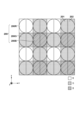
次に、第1の実施形態における撮像素子107の撮像画素と焦点検出画素の配列の概略を図2に示す。図2は、第1の実施形態の撮像素子107としての裏面照射型の2次元CMOSセンサー(撮像素子)の画素(撮像画素)配列を、4列×4行の範囲で、焦点検出画素配列を8列×4行の範囲で示したものである。
[Image sensor]
Next, an outline of the array of imaging pixels and focus detection pixels of the
画素群200は2行×2列の画素からなり、R(赤)の分光感度を有する画素200Rが左上に、G(緑)の分光感度を有する画素200Gが右上と左下に、B(青)の分光感度を有する画素200Bが右下に配置されている。さらに、各画素は2列×1行に配列された第1焦点検出画素201と第2焦点検出画素202により構成されている。
The
図2に示した4列×4行の画素(8列×4行の焦点検出画素)を面上に多数配置し、撮像画像(焦点検出信号)の取得を可能としている。 A large number of 4 columns x 4 rows of pixels (8 columns x 4 rows of focus detection pixels) as shown in Figure 2 are arranged on a surface, making it possible to obtain a captured image (focus detection signal).
図2に示した撮像素子107の1つの画素200Gを、撮像素子107の受光面側(+z側)から見た平面図を図3の3Aに示し、3Aのa-a断面を-y側から見た断面図を図3の3Bに示す。図3に示すように、本実施形態の画素200Gでは、各画素の受光側に入射光を集光するためのマイクロレンズ305及び層内レンズ307が形成され、x方向にNH分割(2分割)、y方向にNV分割(1分割)された光電変換部301と光電変換部302が形成される。光電変換部301,302が、それぞれ、第1焦点検出画素201と第2焦点検出画素202に対応する。
FIG. 3A shows a plan view of one
光電変換部301,302は、それぞれ、p型層とn型層から成るpn接合のフォトダイオードとして構成される。必要に応じて、p型層とn型層との間にイントリンシック層を挟んだpin構造のフォトダイオードとして構成しても良い。
The
画素200Gには、マイクロレンズ305と、層内レンズ307との間に、カラーフィルタ306が設けられている。必要に応じて、画素ごと、または光電変換部ごとにカラーフィルタ306の分光透過率を変えることができる。また、カラーフィルタを省略してもよい。
本実施形態の画素200Gでは、マイクロレンズ305、層内レンズ307、カラーフィルタ306、平坦化層、封止層、絶縁層等で構成されるマイクロレンズ光学系が、受光側に形成されている。また、本実施形態では、光電変換部301,302に対して、マイクロレンズ305及び層内レンズ307とは反対側、すなわち光の入射側とは反対側に、配線層309が形成されている。
In the
図3に示す画素200Gに入射した光は、マイクロレンズ305により集光され、カラーフィルタ306で分光されたのち、更に層内レンズ307により集光されて、光電変換部301,302で受光される。光電変換部301,302では、受光量に応じて電子とホールが対生成し、空乏層で分離された後、負電荷の電子はn型層(不図示)に蓄積され、一方、ホールは定電圧源(不図示)に接続されたp型層を通じて撮像素子107の外部へ排出される。光電変換部301,302のn型層(不図示)に蓄積された電子は、転送ゲートを介して、静電容量部(FD)に転送され、電圧信号に変換されて出力される。
The light incident on the
なお、図2に示す画素200R,200Bも、画素200Gと同様の構成を有し、画素200Gと同様にして、カラーフィルタ306により各色に分光された光に応じた電圧信号を出力する。
Note that
このような構成を有する各画素では、光電変換部301,302からの信号を加算した信号(A+B信号)を撮像信号、個々の光電変換部301,302からそれぞれ読み出した2つの信号(A信号、B信号)を焦点検出信号対として用いる。なお、撮像信号と焦点検出信号とをそれぞれ読み出してもよいが、処理負荷を考慮して、次のようにしてもよい。即ち、撮像信号(A+B信号)と、光電変換部301,302のいずれか一方の焦点検出信号(例えばA信号)とを読み出し、差分を取ることで、視差を有するもう一方の焦点検出信号(例えばB信号)を取得する。
In each pixel having such a configuration, a signal (signal A+B) obtained by adding the signals from the
そして、複数の画素から出力された複数のA信号と複数のB信号をそれぞれ集めることで、撮像面位相差検出方式によるAFに用いられる一対の像信号を得る。そして、該一対の像信号の相対位置をずらしながら重ね合わせ、各ずらし位置において、例えば、波形の差異部分の面積量(相関量)を求める相関演算を行う。この相関量がもっとも小さくなるずらし位置、即ち、最も相関が取れているずれ量である位相差(像ずれ量)を求め、さらに算出した像ずれ量から撮影光学系のデフォーカス量及びデフォーカス方向を算出する。 Then, by collecting multiple A signals and multiple B signals output from multiple pixels, a pair of image signals is obtained to be used for AF using the image plane phase difference detection method. The pair of image signals are then superimposed while shifting the relative positions, and a correlation calculation is performed at each shift position to find, for example, the area of the difference part of the waveform (correlation amount). The shift position at which this correlation amount is smallest, that is, the phase difference (image shift amount) which is the shift amount with the highest correlation, is found, and the defocus amount and defocus direction of the photographing optical system are calculated from the calculated image shift amount.
なお、上述した例では、瞳領域が水平方向に2つに瞳分割されている例を示しているが、必要に応じて、垂直方向に瞳分割を行っても良い。 In the above example, the pupil region is divided into two in the horizontal direction, but the pupil may be divided vertically if necessary.
また、上述した例では第1焦点検出画素と第2焦点検出画素から構成された撮像画素が複数配列されているが、本発明はこれに限られるものではない。必要に応じて、撮像画素と、第1焦点検出画素、第2焦点検出画素を個別の画素構成とし、撮像画素配列の一部に、第1焦点検出画素と第2焦点検出画素を部分的に配置する構成としても良い。 In the above example, multiple imaging pixels each made up of a first focus detection pixel and a second focus detection pixel are arranged, but the present invention is not limited to this. If necessary, the imaging pixel, the first focus detection pixel, and the second focus detection pixel may be arranged as separate pixel configurations, and the first focus detection pixel and the second focus detection pixel may be arranged partially in a portion of the imaging pixel array.
なお、撮像素子107の構成は、上述した構成に限られるものでは無く、撮影光学系の互いに異なる瞳領域を通過した被写体光に基づいて、視差を有する焦点検出信号対を取得可能に信号を出力する焦点検出画素を含む構成であれば良い。
The configuration of the
[瞳分割]
続いて、図4から図6を参照して、本実施形態の撮像素子107の瞳分割機能について説明する。なお、画素200R,200G,200Bは同様の構成を有するため、以下、代表的に画素200Gを用いて説明する。
[Pupil division]
Next, the pupil division function of the
図4は、図3の3Aに示す撮像素子107に配列された画素200Gのa-a断面を+y側から見た断面図、及び、撮像素子107の撮像面600からz軸方向(光軸の方向)に距離Zだけ離れた位置の瞳面を示している。なお、図4では、瞳面の座標軸と対応を取るために、断面図のx軸とy軸を図3に対して反転させている。撮像素子107の撮像面600は、結像光学系の結像面に配置される。
Figure 4 shows a cross-sectional view of the a-a cross section of
第1焦点検出画素201に対応する第1瞳部分領域501は、重心が-x方向に偏心している光電変換部301の受光面と、上述した、マイクロレンズ305や層内レンズ307等で構成されるマイクロレンズ光学系を介して概ね共役関係になっている。このため、第1瞳部分領域501は、第1焦点検出画素201で受光可能な瞳領域を表している。第1瞳部分領域501の重心は、瞳面上で+xp側に偏心している。
The first pupil
同様に、第2焦点検出画素202に対応する第2瞳部分領域502は、重心が+x方向に偏心している光電変換部302の受光面と、マイクロレンズ305や層内レンズ307等で構成されるマイクロレンズ光学系を介して概ね共役関係になっている。このため、第2瞳部分領域502は、第2焦点検出画素202で受光可能な瞳領域を表している。第2瞳部分領域502の重心は、瞳面上で-xp側に偏心している。
Similarly, the second pupil
また、瞳領域500は、光電変換部301,302(第1焦点検出画素201と第2焦点検出画素202)を全て合わせた際の画素200G全体で受光可能な瞳領域である。400は、絞り兼用シャッタ102の開口を表している。
The
次に、図5を参照して、撮像素子107のセンサー入射瞳について説明する。本実施形態の撮像素子107では、面上の各像高座標に位置する画素毎に、マイクロレンズ305及び層内レンズ307(不図示)が、像高座標に応じて、光電変換部301,302に対して撮像素子の中心方向へ連続的にシフトされて配置されている。これにより、撮像素子107の撮像面600から距離Zだけ離れた位置の瞳面において、撮像素子107の各像高座標に配置された各画素の第1焦点検出画素201の受光領域に対応する第1瞳部分領域501が、概ね、一致するように構成されている。同様に、第2焦点検出画素202の受光領域に対応する第2瞳部分領域502が、概ね、一致するように構成されている。つまり、撮像素子107の撮像面600から距離Zだけ離れた位置の瞳面において、撮像素子107の全ての画素の第1瞳部分領域501と第2瞳部分領域502が、概ね、一致するように構成されている。以下、第1瞳部分領域501及び第2瞳部分領域502を、撮像素子107の「センサー入射瞳」と呼び、距離Zを、撮像素子107の「入射瞳距離」と呼ぶ。
Next, the sensor entrance pupil of the
図6は、本実施形態の撮像素子107のセンサー入射瞳による結像光学系の射出瞳400の光学的な分割(瞳分割)を説明する概略図である。被写体からの光束のうち、結像光学系の射出瞳400と第1瞳部分領域501との重なり領域である第1射出瞳領域601を通過した光束は、第1焦点検出画素201(光電変換部301)で受光される。同様に、被写体からの光束のうち、結像光学系の射出瞳400と第2瞳部分領域502との重なり領域である第2射出瞳領域602を通過した光束は、第2焦点検出画素202(光電変換部302)で受光される。
Figure 6 is a schematic diagram illustrating the optical division (pupil division) of the
図4では、撮像素子107の入射瞳距離Zだけ離れた位置の瞳面における第1射出瞳領域601と第2射出瞳領域602を示している。つまり、結像光学系の射出瞳400が、撮像素子107のセンサー入射瞳により、第1射出瞳領域601と第2射出瞳領域602とに分割されることを示している。
Figure 4 shows a first
[画素間クロストーク]
画素200Gへの入射光は、マイクロレンズ光学系により、焦点位置に集光される。しかし、光の波動性による回折の影響のため、集光スポットの直径は回折限界Δより小さくすることはできず、有限の大きさとなる。光電変換部の受光面サイズは約1~2μm程度であり、これに対してマイクロレンズの集光スポットは約1μm程度である。そのため、光電変換部の受光面とマイクロレンズを介して共役の関係にある、図4の第1瞳部分領域501と第2瞳部分領域502は、回折ボケのため、明瞭に瞳分割されず、光の入射角に依存した受光率分布(瞳強度分布)となる。
[Crosstalk between pixels]
The light incident on the
ここで図7を参照して、裏面照射型の撮像素子において発生する画素間クロストークについて説明する。図7は、従来の撮像素子の画素を示す図であり、マイクロレンズ305Bが、その光軸からの距離に依存せずに曲率が一定である。また、層内レンズは形成されない。なお、図7に示す撮像素子において、図3に示す本実施形態の画素と同様の構成には同じ参照番号を付して説明を省略する。 Now, with reference to FIG. 7, we will explain inter-pixel crosstalk that occurs in a back-illuminated imaging element. FIG. 7 is a diagram showing a pixel of a conventional imaging element, in which microlens 305B has a constant curvature independent of its distance from the optical axis. Also, no intralayer lens is formed. Note that in the imaging element shown in FIG. 7, configurations similar to those of the pixel of this embodiment shown in FIG. 3 are given the same reference numbers and will not be described.
図7の7Aは、光軸に平行な角度で入射した光が、曲率一定の球形マイクロレンズ305Bにより集光される状態を示している。また、図7の7Bは、光軸に対して25°の角度で入射した光が、曲率一定の球形マイクロレンズ305Bにより集光される状態を示している。 7A in FIG. 7 shows the state where light incident at an angle parallel to the optical axis is focused by spherical microlens 305B with a constant curvature. Also, 7B in FIG. 7 shows the state where light incident at an angle of 25° to the optical axis is focused by spherical microlens 305B with a constant curvature.
7Aにおいて、球形マイクロレンズ305Bの光軸からの第1の距離をr1p、球形マイクロレンズ305Bの光軸から第2の距離をr2pとする。第1の距離r1pは、第2の距離r2pより小さく、球形マイクロレンズ305Bの光軸に垂直な動径座標上で、第1の距離r1pが内側、第2の距離r2pが外側である。第1の距離r1pでの球形マイクロレンズ305B上の点を第1の主点h1p、焦点距離を第1の焦点距離f1p、焦点位置を第1の焦点位置z1pとする。また、第2の距離r2pでの球形マイクロレンズ305B上の点を第2の主点h2p、焦点距離を第2の焦点距離f2p、焦点位置を第2の焦点位置z2pとする。 In 7A, the first distance from the optical axis of spherical microlens 305B is r1p, and the second distance from the optical axis of spherical microlens 305B is r2p. The first distance r1p is smaller than the second distance r2p, and on the radial coordinate perpendicular to the optical axis of spherical microlens 305B, the first distance r1p is the inside and the second distance r2p is the outside. The point on spherical microlens 305B at the first distance r1p is the first principal point h1p, the focal length is the first focal length f1p, and the focal position is the first focal position z1p. Also, the point on spherical microlens 305B at the second distance r2p is the second principal point h2p, the focal length is the second focal length f2p, and the focal position is the second focal position z2p.
7Aにおいて、球形マイクロレンズ305Bは曲率一定であるため、第2の距離r2pでの第2の焦点距離f2pが、第1の距離r1pでの第1の焦点距離f1pより短い。また、第2の距離r2pでの第2の焦点位置z2pが、第1の距離r1pでの第1の焦点位置z1pよりも、相対的に受光側に位置している。 In 7A, the spherical microlens 305B has a constant curvature, so the second focal length f2p at the second distance r2p is shorter than the first focal length f1p at the first distance r1p. In addition, the second focal position z2p at the second distance r2p is located relatively closer to the light receiving side than the first focal position z1p at the first distance r1p.
そのため、7Bに示す様に光軸に対して25°の角度で光が入射した場合、第2の距離r2pからの光線l2pの光電変換部の受光面への入射位置p2pが、第1の距離r1pからの光線l1pの光電変換部の受光面への入射位置p1pよりも、隣接画素に近くなる。これに加えて、第2の距離r2pからの光線l2pの光電変換部の受光面への入射角度が、第1の距離r1pからの光線l1pの光電変換部の受光面への入射角度よりも、受光面に対して浅く小さい角度(受光面の垂直軸に対して大きい角度)となる。 Therefore, when light is incident at an angle of 25° with respect to the optical axis as shown in 7B, the incident position p2p of the light ray l2p from the second distance r2p on the light receiving surface of the photoelectric conversion unit is closer to the adjacent pixel than the incident position p1p of the light ray l1p from the first distance r1p on the light receiving surface of the photoelectric conversion unit. In addition, the incident angle of the light ray l2p from the second distance r2p on the light receiving surface of the photoelectric conversion unit is shallower and smaller with respect to the light receiving surface (larger with respect to the vertical axis of the light receiving surface) than the incident angle of the light ray l1p from the first distance r1p on the light receiving surface of the photoelectric conversion unit.
したがって、各画素の球形マイクロレンズ305Bは、斜入射光に対して、隣接画素へのクロストークを生じやすい形状となっており、撮像性能が低下する場合がある。そのため、従来の撮像素子では、焦点検出性能を向上するために、マイクロレンズの曲率を小さく、焦点距離を長くし、焦点検出画素の瞳強度分布の入射角変化を大きくした際に、撮像画素の画素間クロストークが生じて、撮像性能が低下する場合がある。 The spherical microlenses 305B of each pixel are therefore shaped in a way that makes them susceptible to crosstalk with adjacent pixels when obliquely incident light strikes them, which can degrade imaging performance. For this reason, in conventional imaging elements, when the curvature of the microlenses is reduced and the focal length is increased to increase the change in the incident angle of the pupil intensity distribution of the focus detection pixel in order to improve focus detection performance, crosstalk between the imaging pixels can occur, degrading imaging performance.
上記現象を鑑みて、本実施形態では、撮像画素の画素間クロストークが抑制されるように、各画素に設けられるマイクロレンズ光学系が、以下で説明する条件となるように構成する。 In consideration of the above phenomenon, in this embodiment, the microlens optical system provided in each pixel is configured to satisfy the conditions described below so that inter-pixel crosstalk between imaging pixels is suppressed.
[マイクロレンズ光学系]
図8から図10を参照して、本第1の実施形態における撮像素子107の各画素に設けられたマイクロレンズ光学系について説明する。なお、本実施形態の画素のマイクロレンズ光学系は、上述した様に、マイクロレンズ305、平坦化層、カラーフィルタ306、層内レンズ307、封止層、絶縁層等で構成されている。また、図8に示す画素構造は、図3に示す画素構造に対応している。
[Microlens optical system]
The microlens optical system provided in each pixel of the
図8の8Aから8Cは、本実施形態の画素に、光軸に平行な角度で入射した光が、光電変換部301,302の受光側に設けられたマイクロレンズ光学系により集光される状態を示している。また、図8の8Dから8Fは、本実施形態の画素に、光軸に対して25°の角度で入射した光が、光電変換部301,302の受光側に設けられたマイクロレンズ光学系により集光される状態を示している。
8A to 8C of FIG. 8 show a state in which light incident on a pixel of this embodiment at an angle parallel to the optical axis is collected by a microlens optical system provided on the light receiving side of the
図8の8A及び8Dにおいて、太線で示す曲線Hは、本実施形態の画素に設けられたマイクロレンズ光学系の主曲面H(の断面)を示しており、マイクロレンズ光学系は、主曲面Hの形状をした単一マイクロレンズと、光学的に略等価の関係にある。したがって、本実施形態の画素は、光電変換部301,302の受光側に、主曲面Hの形状をした単一マイクロレンズが設けられた画素構造と、概ね、光学構造的に等価である。
In Figures 8A and 8D, the thick curve H indicates (a cross section of) the principal curved surface H of the microlens optical system provided in the pixel of this embodiment, and the microlens optical system is approximately optically equivalent to a single microlens having the shape of the principal curved surface H. Therefore, the pixel of this embodiment is roughly optically equivalent to a pixel structure in which a single microlens having the shape of the principal curved surface H is provided on the light receiving side of the
8Aにおいて、マイクロレンズ光学系の光軸からの第1の距離をr1、マイクロレンズ光学系の光軸から第2の距離をr2とする。第1の距離r1は、第2の距離r2より小さく、マイクロレンズ光学系の光軸に垂直な動径座標上で、第1の距離r1が内側、第2の距離r2が外側である。第1の距離r1でのマイクロレンズ光学系の主曲面H上の点を第1の主点h1、焦点距離を第1の焦点距離f1、焦点位置を第1の焦点位置z1とする。また、第2の距離r2でのマイクロレンズ光学系の主曲面上の点を第2の主点h2、焦点距離を第2の焦点距離f2、焦点位置を第2の焦点位置z2とする。 In 8A, the first distance from the optical axis of the microlens optical system is r1, and the second distance from the optical axis of the microlens optical system is r2. The first distance r1 is smaller than the second distance r2, and on a radial coordinate perpendicular to the optical axis of the microlens optical system, the first distance r1 is the inside and the second distance r2 is the outside. The point on the principal curved surface H of the microlens optical system at the first distance r1 is the first principal point h1, the focal length is the first focal length f1, and the focal position is the first focal position z1. Also, the point on the principal curved surface of the microlens optical system at the second distance r2 is the second principal point h2, the focal length is the second focal length f2, and the focal position is the second focal position z2.
図9は、図8の8A及び8Dの本実施形態の画素に設けられたマイクロレンズ光学系の主曲面H(の断面)に接する円を示している。第1の距離r1での主曲面Hに接する円の半径を第1の曲率半径a1とし、第2の距離r2での主曲面Hに接する円の半径を第2の曲率半径a2とする。本実施形態では、第1の距離r1での主曲面の第1の曲率半径a1が、第2の距離r2での主曲面の第2の曲率半径a2より小さく構成する。 Figure 9 shows a circle tangent to the principal curved surface H (cross section) of the microlens optical system provided in the pixels of this embodiment of Figures 8A and 8D. The radius of the circle tangent to the principal curved surface H at the first distance r1 is the first radius of curvature a1, and the radius of the circle tangent to the principal curved surface H at the second distance r2 is the second radius of curvature a2. In this embodiment, the first radius of curvature a1 of the principal curved surface at the first distance r1 is configured to be smaller than the second radius of curvature a2 of the principal curved surface at the second distance r2.
曲率半径の逆数が曲率であることから、本実施形態では、第1の距離r1におけるマイクロレンズ光学系の第1の曲率(1/a1)が、第2の距離r2におけるマイクロレンズ光学系の第2の曲率(1/a2)より大きいように構成する。 Since the reciprocal of the radius of curvature is the curvature, in this embodiment, the first curvature (1/a1) of the microlens optical system at the first distance r1 is configured to be greater than the second curvature (1/a2) of the microlens optical system at the second distance r2.
また、8Aに示す様に、マイクロレンズ光学系が上記条件で構成されているため、第2の距離r2での第2の焦点位置z2が、第1の距離r1での第1の焦点位置z1よりも、相対的に光電変換部301,302側に位置するように構成される。
In addition, as shown in FIG. 8A, since the microlens optical system is configured under the above conditions, the second focal position z2 at the second distance r2 is configured to be located relatively closer to the
8Bは、8Aのマイクロレンズ光学系が設けられた本実施形態の画素に、光軸に平行な角度で円偏光の平面波(波長λ=540nm)が入射した場合の画素内部での光強度分布の例を示している。また、8Cは、受光面での集光スポットの例を示している。 8B shows an example of the light intensity distribution inside a pixel of this embodiment in which the microlens optical system of 8A is provided, when a circularly polarized plane wave (wavelength λ = 540 nm) is incident at an angle parallel to the optical axis. Also, 8C shows an example of a focused spot on the light receiving surface.
8Eは、8Dのマイクロレンズ光学系が設けられた本実施形態の画素に、光軸に対して25°の角度で円偏光の平面波(波長λ=540nm)が入射した場合の画素内部での光強度分布の例を示している。また、8Fは、受光面での集光スポットの例を示している。 8E shows an example of the light intensity distribution inside a pixel of this embodiment in which the microlens optical system of 8D is provided, when a circularly polarized plane wave (wavelength λ = 540 nm) is incident at an angle of 25° to the optical axis. Also, 8F shows an example of a focused spot on the light receiving surface.
このように、8Dで、光軸に対して25°の角度で光が入射した場合、第1の距離r1からの光線l1は、光電変換部の受光面への入射位置p1が、相対的に、第2の距離r2からの光線l2の入射位置p2に対して、画素の内側から離れる。しかしながら、光線l1の光電変換部の受光面への入射角度が深い角度であるため、隣接画素へのクロストークが抑制される。同時に、第2の距離r2からの光線l2は、光電変換部の受光面への入射角度が、相対的に、第1の距離r1からの光線l1の入射角度に対して、浅い角度になる。しかしながら、光線l2の入射位置p2が、光線l1の入射位置p1より、隣接画素から離れて画素の内側に留まるため、隣接画素へのクロストークが抑制される。 In this way, when light is incident at an angle of 25° to the optical axis at 8D, the incident position p1 of the light ray l1 from the first distance r1 on the light receiving surface of the photoelectric conversion unit is relatively farther from the inside of the pixel than the incident position p2 of the light ray l2 from the second distance r2. However, since the incident angle of the light ray l1 on the light receiving surface of the photoelectric conversion unit is deep, crosstalk to adjacent pixels is suppressed. At the same time, the incident angle of the light ray l2 from the second distance r2 on the light receiving surface of the photoelectric conversion unit is relatively shallower than the incident angle of the light ray l1 from the first distance r1. However, since the incident position p2 of the light ray l2 remains farther from the adjacent pixel and inside the pixel than the incident position p1 of the light ray l1, crosstalk to adjacent pixels is suppressed.
このように、本実施形態の撮像素子の画素は、光電変換部に対して受光側に設けられたマイクロレンズ光学系を有し、マイクロレンズ光学系の光軸からの第1の距離r1と、第1の距離r1より長い第2の距離r2において、次の2つの関係を有する。 In this way, the pixels of the image sensor of this embodiment have a microlens optical system provided on the light receiving side of the photoelectric conversion unit, and have the following two relationships between a first distance r1 from the optical axis of the microlens optical system and a second distance r2 that is longer than the first distance r1.
まず、第1の距離r1におけるマイクロレンズ光学系の第1の曲率が、第2の距離r2におけるマイクロレンズ光学系の第2の曲率より大きい。また、第1の距離r1におけるマイクロレンズ光学系の第1の焦点位置z1が、第2の距離r2におけるマイクロレンズ光学系の第2の焦点位置z2よりも、受光側に位置する。 First, the first curvature of the microlens optical system at the first distance r1 is greater than the second curvature of the microlens optical system at the second distance r2. Also, the first focal position z1 of the microlens optical system at the first distance r1 is located closer to the light receiving side than the second focal position z2 of the microlens optical system at the second distance r2.
なお、光電変換部301,302は、屈折率が大きいシリコンSiなどで形成され、光電変換部301,302の上部層は、屈折率が小さい酸化シリコンSiOxなどで形成される。そのため、屈折率が大きい光電変換部301,302に入射する前に、屈折率が小さい光電変換部301,302の上部層で、隣接画素間方向への広がりを抑えることで、隣接画素へのクロストークを効果的に抑制することができる。
The
図10は、本実施形態の画素に設けられたマイクロレンズ光学系の受光面積の割合を示す図である。 Figure 10 shows the ratio of the light receiving area of the microlens optical system provided in the pixel of this embodiment.
隣接画素へのクロストークをより効果的に抑制するには、第1の距離r1からの光線l1の光強度と、第2の距離r2からの光線l2の光強度が、概ね等しいことが望ましい。画素サイズPに内接する半径0.5Pの円の面積を2等分する半径Rcは、Rc=0.5P/√2≒0.35Pである。したがって、画素の画素サイズPに対して、第1の距離r1は、半径Rcの内側の領域(0<r1<0.35P)にあり、第2の距離r2は、半径Rcの外側の領域(0.35P<r2<0.71P)にあることが望ましい。また、マイクロレンズ光学系の4隅の対角コーナー近傍は、隣接画素へのクロストークを抑制するために、遮光層により遮光される場合がある。そのため、画素サイズPに対して、第2の距離r2が、0.35P<r2≦0.5Pの領域にあることが望ましい。 To more effectively suppress crosstalk to adjacent pixels, it is desirable that the light intensity of the light ray l1 from the first distance r1 and the light intensity of the light ray l2 from the second distance r2 are approximately equal. The radius Rc that halves the area of a circle with a radius of 0.5P inscribed in the pixel size P is Rc = 0.5P / √2 ≒ 0.35P. Therefore, it is desirable that the first distance r1 is in the inner region of the radius Rc (0 < r1 < 0.35P) and the second distance r2 is in the outer region of the radius Rc (0.35P < r2 < 0.71P) for the pixel size P of the pixel. In addition, the vicinity of the four diagonal corners of the microlens optical system may be shielded by a light shielding layer in order to suppress crosstalk to adjacent pixels. Therefore, it is desirable that the second distance r2 is in the region of 0.35P < r2 ≦ 0.5P for the pixel size P.
また、マイクロレンズ光学系の光軸近傍は、頂点(極値)形状のため、製造プロセス等により、頂点が平坦化して曲率が変化したり、頂点位置がばらついたりすることがある。この影響を抑制するため、第1の距離r1が、光軸から半径0.5Rcの円の領域(半径Rcの円の面積の1/4の領域)を除いた0.5Rc=0.175P<r1<0.35Pの領域にあることが望ましい。さらに、マイクロレンズ光学系の画素周辺近傍は、隣接画素のマイクロレンズ光学系と接するため、製造プロセス等により、曲率が制約を受ける場合がある。この影響を抑制するため、第2の距離r2が、0.35P<r2≦0.5Pの領域から、半径0.47Pから半径0.5Pのリング領域(半径Rcの円の面積の1/4の領域)を除いた0.35P<r2<0.47Pの領域にあることが望ましい。 In addition, since the vicinity of the optical axis of the microlens optical system has a vertex (extreme value) shape, the vertex may be flattened and the curvature may change or the vertex position may vary due to the manufacturing process, etc. In order to suppress this effect, it is desirable that the first distance r1 is in the region of 0.5Rc = 0.175P < r1 < 0.35P, excluding the region of a circle with a radius of 0.5Rc (region with 1/4 of the area of the circle with a radius of Rc) from the optical axis. Furthermore, since the vicinity of the pixel periphery of the microlens optical system is in contact with the microlens optical system of the adjacent pixel, the curvature may be restricted by the manufacturing process, etc. In order to suppress this effect, it is desirable that the second distance r2 is in the region of 0.35P < r2 < 0.5P, excluding the ring region of radius 0.47P to radius 0.5P (region with 1/4 of the area of the circle with a radius of Rc).
また、図8の8Aに示す様に、第1の距離r1におけるマイクロレンズ光学系の第1の主点h1と第1の焦点位置z1を結ぶ線分h1z1と光軸とが成す角をφ1とし、第1の距離r1におけるマイクロレンズ光学系の見込み角を2φ1とする。また、第1の焦点位置z1での屈折率をnとする。また、光軸に沿った座標をzとする。座標zは、第1の焦点位置z1を原点(z=0)として、マイクロレンズ側を正符号、光電変換部側を負符号とする。 8A, the angle between the optical axis and a line segment h1z1 connecting the first principal point h1 and the first focal position z1 of the microlens optical system at the first distance r1 is φ1 , and the angle of view of the microlens optical system at the first distance r1 is 2φ1 . The refractive index at the first focal position z1 is n. The coordinate along the optical axis is z. The coordinate z has the first focal position z1 as the origin (z=0), and the microlens side has a positive sign and the photoelectric conversion unit side has a negative sign.
第1の距離r1におけるマイクロレンズ光学系の第1の開口数NA1を、以下の式(1)で定義する。
NA1=n・sinφ1 …(1)
また、第1の距離r1におけるマイクロレンズ光学系の第1の絞り値F1を、以下の式(2)で定義する。
F1=1/(2n・sinφ1) …(2)
A first numerical aperture NA 1 of the microlens optical system at a first distance r 1 is defined by the following formula (1).
NA 1 = n・sinφ 1 …(1)
Moreover, a first aperture value F 1 of the microlens optical system at the first distance r1 is defined by the following formula (2).
F 1 =1/(2n・sinφ 1 ) …(2)
第1の距離r1への入射光は、第1の距離r1におけるマイクロレンズ光学系により、第1の焦点位置z1に集光される。しかし、光の波動性により、第1の集光スポットの直径は第1の回折限界Δ1より小さくすることはできない。第1の集光スポットの強度分布をエアリーパターン(Airy pattern)で近似すると、回折限界Δ1は、入射光の波長をλ(可視光域の波長λ=380nm~780nm)として、概ね、以下の式(3)で求まる
Δ1=1.22λ/n・sinφ1=2.44λF1 …(3)
第1の距離r1におけるマイクロレンズ光学系の第1の焦点深度±zD1は、回折限界Δ1を許容錯乱円として、以下の式(4)で求まる。
±zD1=±nF1Δ1 …(4)
なお、第1の焦点深度の範囲は、z軸方向(光軸方向)の座標zに対して、z-zD1<z<z+zD1として表すことができる。
Light incident at a first distance r1 is focused at a first focal position z1 by a microlens optical system at the first distance r1. However, due to the wave nature of light, the diameter of the first focused spot cannot be made smaller than the first diffraction limit Δ1. When the intensity distribution of the first focused spot is approximated by an Airy pattern, the diffraction limit Δ1 is roughly calculated by the following formula (3) where the wavelength of the incident light is λ (wavelength λ in the visible light range is 380 nm to 780 nm): Δ1 = 1.22λ/n· sinφ1 = 2.44λF1 ... (3)
A first focal depth ±z D1 of the microlens optical system at the first distance r1 is determined by the following formula (4) with the diffraction limit Δ 1 as the permissible circle of confusion.
±z D1 = ±nF 1 Δ 1 …(4)
The first range of the depth of focus can be expressed as zz D1 <z<z+z D1 with respect to the coordinate z in the z-axis direction (optical axis direction).
第1の集光スポットの強度分布がガウス分布に近いとすると、第1の集光スポットの直径w1は、座標zの関数として、概ね、以下の式(5)の関係が成り立つ。
w1(z)=Δ1√{1+(z/zR1)2} …(5)
ここで、zR1は、第1の距離r1における第1のレイリー長であり、係数αR=0.61π≒1.92として、zR1=αRzD1で定義される。第1のレイリー長の範囲z-zR1<z<z+zR1では、第1の集光スポットの直径w1は、第1の回折限界Δ1以上、第1の回折限界Δ1の√2倍以下(Δ1≦w1≦√2Δ1≒1.4Δ1)である。
If the intensity distribution of the first focused spot is close to a Gaussian distribution, the diameter w 1 of the first focused spot roughly satisfies the relationship of the following equation (5) as a function of the coordinate z.
w 1 (z) = Δ 1 √{1+(z/z R1 ) 2 } …(5)
Here, z R1 is the first Rayleigh length at the first distance r1, and is defined as z R1 =α R z D1 with a coefficient α R =0.61π≈1.92. In the range of the first Rayleigh length z -z R1 <z<z +z R1 , the diameter w 1 of the first focused spot is equal to or greater than the first diffraction limit Δ1 and equal to or less than √2 times the first diffraction limit Δ 1 (Δ 1 ≦w 1 ≦√2Δ 1 ≈1.4Δ 1 ).
また、第2の距離r2におけるマイクロレンズ光学系の第2のレイリー長zR2、及び、第2のレイリー長の範囲z-zR2<z<z+zR2も同様である。 The same also applies to the second Rayleigh length z R2 of the microlens optical system at the second distance r2, and the range of the second Rayleigh length zz R2 <z<z+z R2 .
本実施形態では、第1の距離r1におけるマイクロレンズ光学系の第1の焦点位置z1は、光電変換部301,302の受光面から前ピン側に構成される。本実施形態では、さらに、第1の距離r1におけるマイクロレンズ光学系の第1の焦点位置z1と光電変換部301,302の受光面までの距離が、第1のレイリー長zR1≒1.92zD1以下となる範囲で、光電変換部301,302の受光面から前ピン側に構成される。これにより、第1の距離r1からの光束により形成される集光スポットの光電変換部301,302の受光面での第1の集光スポット直径w1を、第1の回折限界Δ1の1.4倍以下(w1≦1.4Δ1)に抑制することができる。
In this embodiment, the first focal position z1 of the microlens optical system at the first distance r1 is configured on the front focus side from the light receiving surfaces of the
本実施形態では、光電変換部301,302の受光面が、第1の焦点位置z1から第1のレイリー長の範囲にあり、第2の焦点位置z2から第2のレイリー長の範囲にあるようにマイクロレンズ光学系の主曲面を構成することで、クロストークをより効率的に抑制することができる。
In this embodiment, crosstalk can be more efficiently suppressed by configuring the principal curved surfaces of the microlens optical system so that the light receiving surfaces of the
上記の通り本第1の実施形態によれば、隣接画素へのクロストークを効果的に抑制することができ、これにより、撮像面位相差方式による焦点検出性能と撮像性能を両立させることが可能となる。 As described above, according to the first embodiment, crosstalk to adjacent pixels can be effectively suppressed, making it possible to achieve both focus detection performance and imaging performance using the image plane phase difference method.
また、斜入射光による隣接画素へのクロストークは、光電変換部に対して受光側に配線層がある表面照射型の撮像素子より、光電変換部に対して受光側と反対側に配線層がある裏面照射型の撮像素子で生じやすい。そのため、本実施形態によれば、裏面照射型の撮像素子で、隣接画素へのクロストークをより効果的に抑制することができる。 In addition, crosstalk to adjacent pixels due to obliquely incident light is more likely to occur in back-illuminated image sensors, which have a wiring layer on the opposite side to the light-receiving side of the photoelectric conversion unit, than in front-illuminated image sensors, which have a wiring layer on the light-receiving side of the photoelectric conversion unit. Therefore, according to this embodiment, crosstalk to adjacent pixels can be more effectively suppressed in back-illuminated image sensors.
<第2の実施形態>
次に、本発明の第2の実施形態について説明する。上述した第1の実施形態では、画素に設けられるマイクロレンズ光学系が、1つのマイクロレンズと1つの層内レンズから構成される場合について説明した。しかしながら、本発明はこれに限るものではなく、図8に示すものとは、異なる個数の層内レンズから構成されたマイクロレンズ光学系を用いても良い。
Second Embodiment
Next, a second embodiment of the present invention will be described. In the above-mentioned first embodiment, the microlens optical system provided in the pixel is composed of one microlens and one inner-layer lens. However, the present invention is not limited to this, and a microlens optical system composed of a different number of inner-layer lenses from that shown in FIG. 8 may be used.
図11の11Aから11Fは、本発明の画素に設けられたマイクロレンズ光学系が、1つのマイクロレンズ305と、2つの層内レンズ307,308とを含んで構成されている。上記以外は、上述した第1の実施形態と同様であり、当該構成を有するマイクロレンズ光学系の主曲面Hは、主曲面Hの形状をした単一マイクロレンズと、光学的に略等価の関係を有する。
In Fig. 11A to 11F, the microlens optical system provided in the pixel of the present invention is configured to include one
したがって、第2の実施形態によれば、第1の実施形態と同様の効果を得ることができる。 Therefore, the second embodiment can achieve the same effect as the first embodiment.
なお、第2の実施形態では、画素に設けられるマイクロレンズ光学系が、1つのマイクロレンズと2つの層内レンズを含む例により説明したが、本発明はこれに限定されるものではない。例えば、マイクロレンズ光学系を、1つのマイクロレンズで構成しても良いし、1つのマイクロレンズと3つ以上の層内レンズを含んで構成しても良い。 In the second embodiment, an example has been described in which the microlens optical system provided in a pixel includes one microlens and two in-layer lenses, but the present invention is not limited to this. For example, the microlens optical system may be configured with one microlens, or may include one microlens and three or more in-layer lenses.
<第3の実施形態>
次に、本発明の第3の実施形態について説明する。上述した第1の実施形態では、裏面照射型の撮像素子で構成される場合について説明した。しかしながら、本発明はこれに限られるものではなく、表面照射型の撮像素子であっても良い。
Third Embodiment
Next, a third embodiment of the present invention will be described. In the first embodiment described above, a case where the imaging device is configured as a back-illuminated type imaging device has been described. However, the present invention is not limited to this, and the imaging device may be configured as a front-illuminated type imaging device.
図12の12A及び12Bでは、表面照射型の撮像素子の画素に、図8に示す主曲面Hを有するマイクロレンズ光学系が構成されている。光電変換部301,302に対して、受光側に、配線層310が設けられている。上記以外は、上述した第1の実施形態と同様である。
In 12A and 12B of FIG. 12, a microlens optical system having a principal curved surface H shown in FIG. 8 is configured in the pixel of a front-illuminated image sensor. A wiring layer 310 is provided on the light receiving side of the
したがって、第3の実施形態によれば、第1の実施形態と同様の効果を得ることができる。 Therefore, according to the third embodiment, the same effect as the first embodiment can be obtained.
<第4の実施形態>
次に、本発明の第4の実施形態について説明する。上述した第1の実施形態では、撮像素子107の各画素がx方向に2分割、y方向に1分割(つまり、分割されていない)場合について説明した。しかしながら、本発明はこれに限るものではなく、図2に示すものとは分割数や分割方法が異なる画素から構成された撮像素子107を用いても良い。
Fourth Embodiment
Next, a fourth embodiment of the present invention will be described. In the above-mentioned first embodiment, a case where each pixel of the
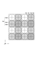
図13は、本実施形態で用いられる撮像素子107の撮像画素と焦点検出画素の配列の概略を示す図である。図13は、2次元CMOSセンサー(撮像素子)の画素(撮像画素)配列を4列×4行の範囲で、焦点検出画素配列を8列×8行の範囲で示したものである。
Figure 13 is a diagram showing an outline of the array of imaging pixels and focus detection pixels of the
本実施形態において、図13に示した画素群700は2行×2列の画素からなり、R(赤)の分光感度を有する画素700Rが左上に、G(緑)の分光感度を有する画素700Gが右上と左下に、B(青)の分光感度を有する画素700Bが右下に配置されている。さらに、各画素は2列×2行に配列された第1焦点検出画素701から第4焦点検出画素704により構成されている。
In this embodiment, the
図13に示した4列×4行の画素(8列×8行の焦点検出画素)を面上に多数配置し、撮像画像(焦点検出信号)の取得を可能としている。 A large number of 4 columns x 4 rows of pixels (8 columns x 8 rows of focus detection pixels) as shown in Figure 13 are arranged on a surface, making it possible to obtain a captured image (focus detection signal).
図13に示した撮像素子107の1つの画素700Gを、撮像素子107の受光面側(+z側)から見た平面図を図14の14Aに示し、14Aのa-a断面を-y側から見た断面図を14Bに示す。図14に示すように、本実施形態の画素700Gでは、各画素の受光側に入射光を集光するためのマイクロレンズ305及び層内レンズ307が形成され、x方向にNH分割(2分割)、y方向にNV分割(2分割)された第1光電変換部801から第4光電変換部804が形成される。第1光電変換部801から第4光電変換部804が、それぞれ、第1焦点検出画素701から第4焦点検出画素704に対応する。
14A of FIG. 14 shows a plan view of one
このような構成では、第1焦点検出画素701と第3焦点検出画素703、第2焦点検出画素702と第4焦点検出画素704の信号をそれぞれ画素内で加算して読み出すことで、図2の第1焦点検出画素201及び第2焦点検出画素202と同様の信号を得ることができる。また、第1焦点検出画素701と第2焦点検出画素702、第3焦点検出画素703と第4焦点検出画素704の受光信号をそれぞれ画素内で加算して読み出すことで、垂直方向に分割した焦点検出信号を得ることができる。なお、画像信号として用いる際には、第1~第4焦点検出画素701~704の信号を加算すれば良い。なお、第1~第4焦点検出画素701~704の一部の信号と、第1~第4焦点検出画素701~704を加算した信号を読み出し、差分することで、一対の焦点検出信号と画像信号を得るようにしても良い。上記以外は、上述した実施形態と同様である。
In this configuration, the signals of the first
以上の構成により、第4の実施形態によれば、第1の実施形態と同様の効果を得ることができる。 With the above configuration, the fourth embodiment can achieve the same effects as the first embodiment.
<第5の実施形態>
次に、本発明の第4の実施形態について説明する。上述した第1~4の実施形態では、図8に示すマイクロレンズ光学系の主曲面Hの形状を有する構成例を用いて説明した。しかしながら、本発明はこれに限るものではなく、第1の実施形態とは異なるマイクロレンズ光学系の主曲面形状を有していても良い。第5の実施形態では、画素間クロストークを抑制すると同時に、位相差焦点検出信号を確保するため、画素内の光電変換部301と光電変換部302間の画素内クロストークを一定量、好適に生じさせる場合の構成例について説明する。
Fifth embodiment
Next, a fourth embodiment of the present invention will be described. In the above-mentioned first to fourth embodiments, a configuration example having a shape of the principal curved surface H of the microlens optical system shown in FIG. 8 has been described. However, the present invention is not limited to this, and the principal curved surface shape of the microlens optical system may be different from that of the first embodiment. In the fifth embodiment, a configuration example will be described in which a certain amount of intra-pixel crosstalk is suitably generated between the
図15の15Aから15Fは、本発明の画素に設けられたマイクロレンズ光学系が、第1の実施形態とは異なる形状の1つのマイクロレンズ1505と、1つの層内レンズ1507とから構成されている。なお、図15に示す撮像素子において、図3に示す画素と同様の構成には同じ参照番号を付して説明を省略する。 In Fig. 15A to 15F, the microlens optical system provided in the pixel of the present invention is composed of one microlens 1505 having a shape different from that of the first embodiment, and one inner-layer lens 1507. Note that in the image sensor shown in Fig. 15, the same reference numerals are used for the same components as those in the pixel shown in Fig. 3, and the description thereof is omitted.
図15の15Aから15Cは、本実施形態の画素に、光軸に平行な角度で入射した光が、光電変換部301,302の受光側に設けられたマイクロレンズ光学系により集光される状態を示している。また、図15の15Dから15Fは、本実施形態の画素に、光軸に対して25°の角度で入射した光が、光電変換部301,302の受光側に設けられたマイクロレンズ光学系により集光される状態を示している。
15A to 15C of FIG. 15 show a state in which light incident on a pixel of this embodiment at an angle parallel to the optical axis is collected by a microlens optical system provided on the light receiving side of the
なお、本実施形態におけるマイクロレンズ光学系は、マイクロレンズ1505、平坦化層、カラーフィルタ、層内レンズ1507、封止層、絶縁層等で構成されている。 In addition, the microlens optical system in this embodiment is composed of a microlens 1505, a planarization layer, a color filter, an inner-layer lens 1507, a sealing layer, an insulating layer, etc.
図15の15A及び15Dにおいて、太線で示す曲線H’は、本実施形態の画素に設けられたマイクロレンズ光学系の主曲面H’(の断面)を示しており、マイクロレンズ光学系は、主曲面H’の形状をした単一マイクロレンズと、光学的に略等価の関係にある。したがって、本実施形態の画素は、光電変換部301,302の受光側に、主曲面H’の形状をした単一マイクロレンズが設けられた画素構造と、概ね、光学構造的に等価である。
In Figures 15A and 15D, the thick curve H' indicates the cross section of the principal curved surface H' of the microlens optical system provided in the pixel of this embodiment, and the microlens optical system is approximately optically equivalent to a single microlens having the shape of the principal curved surface H'. Therefore, the pixel of this embodiment is roughly optically equivalent to a pixel structure in which a single microlens having the shape of the principal curved surface H' is provided on the light receiving side of the
15Aにおいて、マイクロレンズ光学系の光軸から第0の距離をr50、マイクロレンズ光学系の光軸からの第1の距離をr51、マイクロレンズ光学系の光軸から第2の距離をr52とする。第0の距離r50から第2の距離r52は、マイクロレンズ光学系の光軸に垂直な動径座標上で、第0の距離r50<第1の距離r51<第2の距離r52の大小関係にあり、第0の距離r50が中央寄り、第1の距離r51が中間、第2の距離r52が周辺である。 In 15A, the zeroth distance from the optical axis of the microlens optical system is r50, the first distance from the optical axis of the microlens optical system is r51, and the second distance from the optical axis of the microlens optical system is r52. The zeroth distance r50 to the second distance r52 have a magnitude relationship of zeroth distance r50 < first distance r51 < second distance r52 on the radial coordinate perpendicular to the optical axis of the microlens optical system, with the zeroth distance r50 being closer to the center, the first distance r51 being in the middle, and the second distance r52 being the periphery.
第0の距離r50でのマイクロレンズ光学系の主曲面H’上の点を第0の主点h50、焦点距離を第0の焦点距離f50、焦点位置を第0の焦点位置z50とする。また、第1の距離r51でのマイクロレンズ光学系の主曲面上の点を第1の主点h51、焦点距離を第1の焦点距離f51、焦点位置を第1の焦点位置z51とする。さらに、第2の距離r52でのマイクロレンズ光学系の主曲面上の点を第2の主点h52、焦点距離を第2の焦点距離f52、焦点位置を第2の焦点位置z52とする。 The point on the principal curved surface H' of the microlens optical system at the zeroth distance r50 is the zeroth principal point h50, the focal length is the zeroth focal length f50, and the focal position is the zeroth focal position z50. Furthermore, the point on the principal curved surface of the microlens optical system at the first distance r51 is the first principal point h51, the focal length is the first focal length f51, and the focal position is the first focal position z51. Furthermore, the point on the principal curved surface of the microlens optical system at the second distance r52 is the second principal point h52, the focal length is the second focal length f52, and the focal position is the second focal position z52.
本実施形態では、第1の距離r51におけるマイクロレンズ光学系の第1の曲率を、第2の距離r52におけるマイクロレンズ光学系の第2の曲率より大きく構成する。 In this embodiment, the first curvature of the microlens optical system at the first distance r51 is configured to be greater than the second curvature of the microlens optical system at the second distance r52.
15Aに示す様に、マイクロレンズ光学系が上記条件で構成されているため、第2の距離r52での第2の焦点位置z52が、第1の距離r51での第1の焦点位置z51よりも、相対的に光電変換部301,302側に位置するように構成される。
As shown in FIG. 15A, the microlens optical system is configured under the above conditions, so that the second focal position z52 at the second distance r52 is configured to be located relatively closer to the
15Bは、15Aのマイクロレンズ光学系が設けられた本実施形態の画素に、光軸に平行な角度で円偏光の平面波(波長λ=540nm)が入射した場合の画素内部での光強度分布の例を示している。また、15Cは、受光面での集光スポットの例を示している。 15B shows an example of the light intensity distribution inside a pixel of this embodiment in which the microlens optical system of 15A is provided, when a circularly polarized plane wave (wavelength λ = 540 nm) is incident at an angle parallel to the optical axis. 15C shows an example of a focused spot on the light receiving surface.
上記構成において、15Dに示す様に、光軸に対して25°の角度で光が入射した場合、第1の距離r51からの光線l51は、光電変換部の受光面への入射位置p51が、相対的に、第2の距離r52からの光線l52の入射位置p52に対して、画素の内側から離れる。しかしながら、光線l51の光電変換部の受光面への入射角度が深い角度であるため、隣接画素へのクロストークが抑制される。同時に、第2の距離r52からの光線l52は、光電変換部の受光面への入射角度が、相対的に、第1の距離r51からの光線l51の入射角度に対して、浅い角度になる。しかしながら、光線l52の入射位置p52が、光線l51の入射位置p51より、隣接画素から離れて画素の内側に留まるため、隣接画素へのクロストークが抑制される。 In the above configuration, as shown in FIG. 15D, when light is incident at an angle of 25° with respect to the optical axis, the incident position p51 of the light ray l51 from the first distance r51 on the light receiving surface of the photoelectric conversion unit is relatively farther from the inside of the pixel than the incident position p52 of the light ray l52 from the second distance r52. However, since the incident angle of the light ray l51 on the light receiving surface of the photoelectric conversion unit is deep, crosstalk to adjacent pixels is suppressed. At the same time, the incident angle of the light ray l52 from the second distance r52 on the light receiving surface of the photoelectric conversion unit is relatively shallower than the incident angle of the light ray l51 from the first distance r51. However, since the incident position p52 of the light ray l52 remains farther from the adjacent pixel and inside the pixel than the incident position p51 of the light ray l51, crosstalk to adjacent pixels is suppressed.
画素サイズPに内接する半径0.5Pの円の面積を3等分する第1の半径Rc1=0.5P/√3≒0.29P、第2の半径Rc2=0.5P/√3×√2≒0.41Pとする。隣接画素へのクロストークをより効果的に抑制するために、第0の距離r50からの光強度と、第1の距離r51からの光強度と、第2の距離r52からの光強度が、概ね、等しいことが望ましい。したがって、本実施形態では、第0の距離r50は、半径Rc1の内側の領域(0<第0の距離r50<0.29P)にあり、第1の距離r51は、半径Rc1から半径Rc2の領域(0.29P<第1の距離r51<0.41P)にあり、第2の距離r52は、半径Rc2の外側の領域(0.41P<第2の距離r52<0.71P)にあるように構成される。また、マイクロレンズ光学系の4隅の対角コーナー近傍は、隣接画素へのクロストークを抑制するために、遮光層により遮光される場合がある。そのため、画素サイズPに対して、第2の距離r52が、0.41P<第2の距離r52≦0.5Pの領域にあることが望ましい。また、マイクロレンズ光学系の光軸近傍は、頂点(極値)形状のため、製造プロセス等により、頂点が平坦化して曲率が変化したり、頂点位置がばらついたりすることがある。この影響を抑制するため、第0の距離r50が、光軸から半径0.5Rc1の円の領域(半径Rc1の円の面積の1/4の領域)を除いた0.5Rc1=0.145P<第0の距離r50<0.29Pの領域にあることが望ましい。さらに、マイクロレンズ光学系の画素周辺近傍は、隣接画素のマイクロレンズ光学系と接するため、製造プロセス等により、曲率が制約を受ける場合がある。この影響を抑制するため、第2の距離r52が、0.41P<第2の距離r52≦0.5Pの領域から、半径0.48Pから半径0.5Pのリング領域(半径Rc1の円の面積の1/4の領域)を除いた0.41P<第2の距離r52<0.48Pの領域にあることが望ましい。 The area of a circle with a radius of 0.5P inscribed in the pixel size P is divided into three equal parts, the first radius Rc1 = 0.5P / √3 ≒ 0.29P, and the second radius Rc2 = 0.5P / √3 × √2 ≒ 0.41P. In order to more effectively suppress crosstalk to adjacent pixels, it is desirable that the light intensity from the 0th distance r50, the light intensity from the first distance r51, and the light intensity from the second distance r52 are approximately equal. Therefore, in this embodiment, the 0th distance r50 is in the inner region of the radius Rc1 (0 < 0th distance r50 < 0.29P), the first distance r51 is in the region from the radius Rc1 to the radius Rc2 (0.29P < the first distance r51 < 0.41P), and the second distance r52 is in the outer region of the radius Rc2 (0.41P < the second distance r52 < 0.71P). In addition, the vicinity of the four diagonal corners of the microlens optical system may be shielded by a light shielding layer to suppress crosstalk to adjacent pixels. Therefore, it is preferable that the second distance r52 is in the region of 0.41P<second distance r52≦0.5P for the pixel size P. In addition, since the vicinity of the optical axis of the microlens optical system has a vertex (extreme value) shape, the vertex may be flattened and the curvature may change or the vertex position may vary due to the manufacturing process, etc. In order to suppress this effect, it is preferable that the zeroth distance r50 is in the region of 0.5Rc1=0.145P<zeroth distance r50<0.29P, excluding the region of a circle with a radius of 0.5Rc1 from the optical axis (region that is 1/4 of the area of the circle with a radius of Rc1). Furthermore, since the vicinity of the pixel periphery of the microlens optical system is in contact with the microlens optical system of the adjacent pixel, the curvature may be restricted due to the manufacturing process, etc. To suppress this effect, it is desirable for the second distance r52 to be in the region of 0.41P < second distance r52 < 0.48P, excluding the ring region of radius 0.48P to radius 0.5P (a region that is 1/4 the area of the circle of radius Rc1) from the region of 0.41P < second distance r52 ≦ 0.5P.
なお、光電変換部301,302は、屈折率が大きいシリコンSiなどで形成され、光電変換部301,302の上部層は、屈折率が小さい酸化シリコンSiOxなどで形成される。そのため、屈折率が大きい光電変換部301,302に入射する前に、屈折率が小さい光電変換部301,302の上部層で、隣接画素間方向への広がりを抑えることで、隣接画素へのクロストークを効果的に抑制することができる。
The
このように、第5の実施形態の撮像素子の画素は、光電変換部に対して受光側に設けられたマイクロレンズ光学系を有し、マイクロレンズ光学系の光軸からの第1の距離r51と、第1の距離より長い第2の距離r52において、次の2つの関係を有する。 In this way, the pixels of the image sensor of the fifth embodiment have a microlens optical system provided on the light receiving side of the photoelectric conversion unit, and have the following two relationships between a first distance r51 from the optical axis of the microlens optical system and a second distance r52 that is longer than the first distance.
まず、第1の距離r51におけるマイクロレンズ光学系の第1の曲率が、第2の距離r52におけるマイクロレンズ光学系の第2の曲率より大きい。また、第1の距離r51におけるマイクロレンズ光学系の第1の焦点位置z51が、第2の距離r52におけるマイクロレンズ光学系の第2の焦点位置z52より、受光側に位置する。 First, the first curvature of the microlens optical system at the first distance r51 is greater than the second curvature of the microlens optical system at the second distance r52. Also, the first focal position z51 of the microlens optical system at the first distance r51 is located on the light receiving side more than the second focal position z52 of the microlens optical system at the second distance r52.
さらに、本実施形態では、上述した画素間クロストークを抑制する構成に加えて、画素内の光電変換部301と光電変換部302間の画素内クロストークを一定量、好適に生じさせ、位相差焦点検出信号を確保するため、以下の条件を満たすように構成される。
Furthermore, in this embodiment, in addition to the configuration for suppressing the inter-pixel crosstalk described above, a certain amount of intra-pixel crosstalk is preferably generated between the
15Aに示す様に、本実施形態では、第0の距離r50におけるマイクロレンズ光学系の第0の曲率を、第1の距離r51におけるマイクロレンズ光学系の第1の曲率より小さく構成する。 As shown in FIG. 15A, in this embodiment, the zeroth curvature of the microlens optical system at the zeroth distance r50 is configured to be smaller than the first curvature of the microlens optical system at the first distance r51.
また、15Aに示す様に、本実施形態では、第0の距離r50におけるマイクロレンズ光学系の第0の焦点距離f50を、第1の距離r51におけるマイクロレンズ光学系の第1の焦点距離f51より長く構成する。 Furthermore, as shown in FIG. 15A, in this embodiment, the zeroth focal length f50 of the microlens optical system at the zeroth distance r50 is configured to be longer than the first focal length f51 of the microlens optical system at the first distance r51.
さらに、15Aに示す様に、本実施形態では、第0の距離r50におけるマイクロレンズ光学系の第0の焦点位置z50を、第1の距離r51におけるマイクロレンズ光学系の第1の焦点位置z51よりも、相対的に光電変換部301,302側に位置するように構成する。また、光電変換部301,302の受光面から第1の焦点位置z51までの距離が、光電変換部301,302の受光面から第0の焦点位置z50までの距離、及び、光電変換部301,302の受光面から第2の焦点位置z52までの距離よりも長くなるように構成する。
Furthermore, as shown in FIG. 15A, in this embodiment, the zeroth focal position z50 of the microlens optical system at the zeroth distance r50 is configured to be located relatively closer to the
また、15Aに示す様に、第1の距離r51におけるマイクロレンズ光学系の第1の主点h51と第1の焦点位置z51を結ぶ線分h51z51と光軸とが成す角をφ1とし、第1の距離r51におけるマイクロレンズ光学系の見込み角を2φ1とする。また、第1の焦点位置z51での屈折率をnとする。また、光軸に沿った座標をzとする。座標zは、第1の焦点位置z51を原点(z=0)として、マイクロレンズ側を正符号、光電変換部側を負符号とする。 As shown in FIG. 15A, the angle between the optical axis and a line segment h51z51 connecting the first principal point h51 and the first focal position z51 of the microlens optical system at the first distance r51 is φ1 , and the angle of view of the microlens optical system at the first distance r51 is 2φ1 . The refractive index at the first focal position z51 is n. The coordinate along the optical axis is z. The coordinate z has the first focal position z51 as the origin (z=0), and the microlens side has a positive sign and the photoelectric conversion unit side has a negative sign.
第1の距離r51におけるマイクロレンズ光学系の第1の開口数NA1を、以下の式(1)で定義する。
NA1=n・sinφ1 …(1)
また、第1の距離r51におけるマイクロレンズ光学系の第1の絞り値F1を、以下の式(2)で定義する。
F1=1/(2n・sinφ1) …(2)
A first numerical aperture NA 1 of the microlens optical system at a first distance r51 is defined by the following formula (1).
NA 1 = n・sinφ 1 …(1)
Moreover, a first aperture value F 1 of the microlens optical system at the first distance r51 is defined by the following formula (2).
F 1 =1/(2n・sinφ 1 ) …(2)
第1の距離r51への入射光は、第1の距離r51におけるマイクロレンズ光学系により、第1の焦点位置z51に集光される。しかし、光の波動性により、第1の集光スポットの直径は第1の回折限界Δ1より小さくすることはできない。第1の集光スポットの強度分布をエアリーパターン(Airy pattern)で近似すると、回折限界Δ1は、入射光の波長をλ(可視光域の波長λ=380nm~780nm)として、概ね、以下の式(3)で求まる。
Δ1=1.22λ/n・sinφ1=2.44λF1 …(3)
第1の距離r51におけるマイクロレンズ光学系の第1の焦点深度±zD1は、回折限界Δ1を許容錯乱円として、以下の式(4)で求まる。
±zD1=±nF1Δ1 …(4)
なお、第1の焦点深度の範囲は、z軸方向(光軸方向)の座標zに対して、z-zD1<z<z+zD1として表すことができる。
Light incident at a first distance r51 is focused at a first focal position z51 by a microlens optical system at the first distance r51. However, due to the wave nature of light, the diameter of the first focused spot cannot be made smaller than the first diffraction limit Δ 1. When the intensity distribution of the first focused spot is approximated by an Airy pattern, the diffraction limit Δ 1 is roughly determined by the following formula (3), where λ is the wavelength of the incident light (λ in the visible light region is 380 nm to 780 nm).
Δ 1 = 1.22λ/n・sinφ 1 = 2.44λF 1 …(3)
The first focal depth ±z D1 of the microlens optical system at the first distance r51 is determined by the following formula (4) with the diffraction limit Δ 1 as the permissible circle of confusion.
±z D1 = ±nF 1 Δ 1 …(4)
The first range of the depth of focus can be expressed as zz D1 <z<z+z D1 with respect to the coordinate z in the z-axis direction (optical axis direction).
第1の集光スポットの強度分布がガウス分布に近いとすると、第1の集光スポットの直径w1は、座標zの関数として、概ね、以下の式(5)の関係が成り立つ。
w1(z)=Δ1√{1+(z/zR1)2} …(5)
ここで、zR1は、第1の距離r51における第1のレイリー長であり、係数αR=0.61π≒1.92として、zR1=αRzD1で定義される。第1のレイリー長の範囲z-zR1<z<z+zR1では、第1の集光スポットの直径w1は、第1の回折限界Δ1以上、第1の回折限界Δ1の√2倍以下(Δ1≦w1≦√2Δ1≒1.4Δ1)である。
If the intensity distribution of the first focused spot is close to a Gaussian distribution, the diameter w 1 of the first focused spot roughly satisfies the relationship of the following equation (5) as a function of the coordinate z.
w 1 (z) = Δ 1 √{1+(z/z R1 ) 2 } …(5)
Here, z R1 is the first Rayleigh length at the first distance r51, and is defined as z R1 =α R z D1 with a coefficient α R =0.61π≈1.92. In the range of the first Rayleigh length z -z R1 <z<z +z R1 , the diameter w 1 of the first focused spot is equal to or greater than the first diffraction limit Δ 1 and equal to or less than √2 times the first diffraction limit Δ 1 (Δ 1 ≦w 1 ≦√2Δ 1 ≈1.4Δ 1 ).
また、第2の距離r52におけるマイクロレンズ光学系の第2のレイリー長zR2、及び、第2のレイリー長の範囲z-zR2<z<z+zR2も同様である。
さらに、第0の距離r50におけるマイクロレンズ光学系の第0のレイリー長zR0、及び、第0のレイリー長の範囲z-zR0<z<z+zR0も同様である。
The same applies to the second Rayleigh length z R2 of the microlens optical system at the second distance r52, and the range of the second Rayleigh length zz R2 <z<z+z R2 .
Furthermore, the same applies to the zeroth Rayleigh length z R0 of the microlens optical system at the zeroth distance r50, and the range of the zeroth Rayleigh length zz R0 <z<z+z R0 .
本実施形態では、第1の距離r51におけるマイクロレンズ光学系の第1の焦点位置z51は、光電変換部301,302の受光面から前ピン側に構成される。本実施形態では、さらに、第1の距離r51におけるマイクロレンズ光学系の第1の焦点位置z51と光電変換部301,302の受光面までの距離が、第1のレイリー長zR1≒1.92zD1以下となる範囲で、光電変換部301,302の受光面から前ピン側に構成される。これにより、第1の距離r51からの光束により形成される集光スポットの光電変換部301,302の受光面での第1の集光スポット直径w1を、第1の回折限界Δ1の1.4倍以下(w1≦1.4Δ1)に抑制することができる。
In this embodiment, the first focal position z51 of the microlens optical system at the first distance r51 is configured on the front focus side from the light receiving surfaces of the
本実施形態では、光電変換部301,302の受光面が、第1の焦点位置z51から第1のレイリー長の範囲にあり、第2の焦点位置z52から第2のレイリー長の範囲にあるようにマイクロレンズ光学系の主曲面を構成することで、クロストークをより効率的に抑制することができる。さらに、光電変換部301,302の受光面が、第0の焦点位置z50から第0のレイリー長の範囲にあるようにマイクロレンズ光学系の主曲面を構成することで、クロストークをより効率的に抑制することができる。
In this embodiment, crosstalk can be more efficiently suppressed by configuring the principal curved surfaces of the microlens optical system so that the light receiving surfaces of the
上記構成により、15Dに示す様に、光軸に対して25°の角度で光が入射した場合、第1の距離r51からの光束は、光電変換部の受光面において、第1の回折限界Δ1から1.4Δ1程度に入射位置p51から入射位置p51’まで拡がる。これに対して、第0の距離r50からの光束が集光して入射する第0の入射位置p50と、第2の距離r52からの光束の拡がりである第2の入射位置p52から第2の入射位置p52’は、いずれも、第1の距離r51からの光束の拡がりである入射位置p51から入射位置p51’の略範囲内に含まれる。したがって、マイクロレンズ光学系に入射する全光束から形成される集光スポットの光電変換部301,302の受光面での集光スポット直径を、第1の回折限界Δ1の1.4倍以下(w1≦1.4Δ1)に抑制することができ、瞳分離性能を良好に保つことができる。
With the above configuration, as shown in FIG. 15D, when light is incident at an angle of 25° with respect to the optical axis, the light flux from the first distance r51 spreads from the incident position p51 to the incident position p51' on the light receiving surface of the photoelectric conversion unit from the first diffraction limit Δ 1 to about 1.4Δ 1. In contrast, the zeroth incident position p50 where the light flux from the zeroth distance r50 is condensed and incident, and the second incident position p52 to the second incident position p52' which are the spread of the light flux from the second distance r52, are both included within the approximate range of the incident position p51 to the incident position p51' which are the spread of the light flux from the first distance r51. Therefore, the diameter of the focused spot formed on the light receiving surface of the
また、上記構成により、第1の距離r51からの光束の一部が、光電変換部の受光面において、画素中心方向に、入射位置p51’まで拡がるため、画素内の光電変換部301と光電変換部302間の画素内クロストークが一定量生じる。第1の焦点位置z51の光電変換部301,302の受光面からの前ピン量を調整することで、画素内クロストーク量を、好適に調整することが可能である。したがって、本実施形態では、画素間クロストークを抑制すると同時に、瞳分離性能を良好に保持して、画素内の光電変換部301と光電変換部302間の画素内クロストークを一定量、好適に生じさせることができる。そのため、結像光学系の条件によって、光電変換部301と光電変換部302のどちらか一方に受光量が偏った場合でも、位相差焦点検出信号として必要最低限の受光量を確保することができる。
In addition, with the above configuration, a portion of the light flux from the first distance r51 spreads to the incident position p51' in the pixel center direction on the light receiving surface of the photoelectric conversion unit, so that a certain amount of intra-pixel crosstalk occurs between the
15Eは、15Dのマイクロレンズ光学系が設けられた本実施形態の画素に、光軸に対して25°の角度で円偏光の平面波(波長λ=540nm)が入射した場合の画素内部での光強度分布の例を示している。また、15Fは、受光面での集光スポットの例を示している。 15E shows an example of the light intensity distribution inside a pixel of this embodiment in which the microlens optical system of 15D is provided, when a circularly polarized plane wave (wavelength λ = 540 nm) is incident at an angle of 25° to the optical axis. 15F shows an example of a focused spot on the light receiving surface.
上記の通り本第5の実施形態によれば、隣接画素へのクロストークを効果的に抑制することができると共に、位相差焦点検出信号として必要最低限の受光量を確保することができる。これにより、撮像面位相差方式による焦点検出性能と撮像性能を両立させることが可能となる。 As described above, according to the fifth embodiment, it is possible to effectively suppress crosstalk to adjacent pixels and ensure the minimum amount of light required for a phase difference focus detection signal. This makes it possible to achieve both focus detection performance and imaging performance using the image plane phase difference method.
本発明は上記実施の形態に制限されるものではなく、本発明の精神及び範囲から離脱することなく、様々な変更及び変形が可能である。従って、本発明の範囲を公にするために、以下の請求項を添付する。 The present invention is not limited to the above-described embodiments, and various modifications and variations are possible without departing from the spirit and scope of the present invention. Therefore, in order to publicize the scope of the present invention, the following claims are appended.
Claims (12)
少なくとも1つの光電変換部と、
前記光電変換部よりも光が入射する側に設けられたマイクロレンズ光学系と、を含み、
前記マイクロレンズ光学系の主曲面の形状が、前記マイクロレンズ光学系の光軸からの第1の距離における前記マイクロレンズ光学系の第1の曲率が、前記第1の距離よりも前記マイクロレンズ光学系の光軸から遠い第2の距離における前記マイクロレンズ光学系の第2の曲率よりも大きく、さらに、前記マイクロレンズ光学系の光軸からの前記第1の距離における前記マイクロレンズ光学系の前記第1の曲率が、前記第1の距離よりも前記マイクロレンズ光学系の光軸から近い第3の距離における前記マイクロレンズ光学系の第3の曲率よりも大きいことを特徴とする撮像素子。 An image sensor having a plurality of pixels including a focus detection pixel that outputs a signal so that a pair of focus detection signals having parallax can be obtained based on light beams that have passed through different pupil regions of an image forming optical system, each pixel comprising:
At least one photoelectric conversion unit;
a microlens optical system provided on a light-incident side of the photoelectric conversion unit,
An imaging element characterized in that the shape of the principal curved surface of the microlens optical system is such that a first curvature of the microlens optical system at a first distance from the optical axis of the microlens optical system is greater than a second curvature of the microlens optical system at a second distance that is farther from the optical axis of the microlens optical system than the first distance, and further, the first curvature of the microlens optical system at the first distance from the optical axis of the microlens optical system is greater than a third curvature of the microlens optical system at a third distance that is closer to the optical axis of the microlens optical system than the first distance .
少なくとも1つの光電変換部と、
前記光電変換部よりも光が入射する側に設けられたマイクロレンズ光学系と、を含み、
前記マイクロレンズ光学系の主曲面の形状が、前記マイクロレンズ光学系の光軸からの第1の距離における前記マイクロレンズ光学系の第1の焦点位置が、前記第1の距離よりも前記マイクロレンズ光学系の光軸から遠い第2の距離における前記マイクロレンズ光学系の第2の焦点位置よりも、光が入射する側にあり、さらに、前記マイクロレンズ光学系の光軸からの前記第1の距離における前記マイクロレンズ光学系の第1の焦点位置が、前記第1の距離よりも前記マイクロレンズ光学系の光軸から近い第3の距離における前記マイクロレンズ光学系の第3の焦点位置よりも、光が入射する側にあることを特徴とする撮像素子。 An image sensor having a plurality of pixels including a focus detection pixel that outputs a signal so that a pair of focus detection signals having parallax can be obtained based on light beams that have passed through different pupil regions of an image forming optical system, each pixel comprising:
At least one photoelectric conversion unit;
a microlens optical system provided on a light-incident side of the photoelectric conversion unit,
an imaging element characterized in that the shape of the principal curved surface of the microlens optical system is such that a first focal position of the microlens optical system at a first distance from the optical axis of the microlens optical system is on the light incident side of a second focal position of the microlens optical system at a second distance that is farther from the optical axis of the microlens optical system than the first distance, and further, that the first focal position of the microlens optical system at the first distance from the optical axis of the microlens optical system is on the light incident side of a third focal position of the microlens optical system at a third distance that is closer to the optical axis of the microlens optical system than the first distance .
少なくとも1つの光電変換部と、
前記光電変換部よりも光が入射する側に設けられたマイクロレンズ光学系と、を含み、
前記マイクロレンズ光学系の主曲面の形状が、前記マイクロレンズ光学系の光軸からの第1の距離における前記マイクロレンズ光学系の第1の曲率が、前記第1の距離よりも前記マイクロレンズ光学系の光軸から遠い第2の距離における前記マイクロレンズ光学系の第2の曲率よりも大きく、
前記画素の画素サイズをP、前記第1の距離をr1、前記第2の距離をr2とした場合に、
r1<0.35P<r2
を満たすことを特徴とする撮像素子。 An image sensor having a plurality of pixels including a focus detection pixel that outputs a signal so that a pair of focus detection signals having parallax can be obtained based on light beams that have passed through different pupil regions of an image forming optical system, each pixel comprising:
At least one photoelectric conversion unit;
a microlens optical system provided on a light-incident side of the photoelectric conversion unit,
a shape of a principal curved surface of the microlens optical system such that a first curvature of the microlens optical system at a first distance from an optical axis of the microlens optical system is larger than a second curvature of the microlens optical system at a second distance farther from the optical axis of the microlens optical system than the first distance;
When the pixel size of the pixel is P, the first distance is r1, and the second distance is r2,
r1<0.35P<r2
An imaging element satisfying the above.
r2≦P
を満たすことを特徴とする請求項3に記載の撮像素子。 When the pixel size of the pixel is P and the second distance is r2,
r2≦P
4. The imaging device according to claim 3, wherein the following is satisfied.
0≦r0<0.29P≦r1<0.41P<r2≦0.5P
を満たすことを特徴とする請求項1または2に記載の撮像素子。 When the pixel size of the pixel is P, the first distance is r1, the second distance is r2, and the third distance is r0,
0≦r0<0.29P≦r1<0.41P<r2≦0.5P
3. The imaging device according to claim 1 , wherein the following is satisfied:
前記結像光学系と、
前記撮像素子から出力された信号を処理する処理手段と
を有することを特徴とする撮像装置。 The imaging device according to claim 1 ,
The imaging optical system;
and a processing means for processing a signal output from the imaging element.
請求項1乃至4のいずれか1項に記載の撮像素子と、
前記撮像素子から出力された信号を処理する処理手段と
を有することを特徴とする撮像装置。 An imaging device to which an imaging optical system can be detachably attached,
The imaging device according to claim 1 ,
and a processing means for processing a signal output from the imaging element.
Priority Applications (6)
| Application Number | Priority Date | Filing Date | Title |
|---|---|---|---|
| PCT/JP2020/016448 WO2020213610A1 (en) | 2019-04-15 | 2020-04-14 | Image capturing element and image capturing device |
| EP20791352.6A EP3958022A4 (en) | 2019-04-15 | 2020-04-14 | IMAGE CAPTURE ELEMENT AND IMAGE CAPTURE DEVICE |
| CN202080028678.4A CN113728253A (en) | 2019-04-15 | 2020-04-14 | Image sensor and image pickup apparatus |
| CN202311612862.5A CN117572545A (en) | 2019-04-15 | 2020-04-14 | Image sensors and camera equipment |
| US17/496,955 US12261184B2 (en) | 2019-04-15 | 2021-10-08 | Image sensor and image capturing apparatus |
| US19/057,441 US20250194278A1 (en) | 2019-04-15 | 2025-02-19 | Image sensor and image capturing apparatus |
Applications Claiming Priority (2)
| Application Number | Priority Date | Filing Date | Title |
|---|---|---|---|
| JP2019077356 | 2019-04-15 | ||
| JP2019077356 | 2019-04-15 |
Publications (2)
| Publication Number | Publication Date |
|---|---|
| JP2020178120A JP2020178120A (en) | 2020-10-29 |
| JP7561514B2 true JP7561514B2 (en) | 2024-10-04 |
Family
ID=72936522
Family Applications (1)
| Application Number | Title | Priority Date | Filing Date |
|---|---|---|---|
| JP2020070011A Active JP7561514B2 (en) | 2019-04-15 | 2020-04-08 | Image pickup element and image pickup device |
Country Status (2)
| Country | Link |
|---|---|
| JP (1) | JP7561514B2 (en) |
| CN (1) | CN113728253A (en) |
Families Citing this family (2)
| Publication number | Priority date | Publication date | Assignee | Title |
|---|---|---|---|---|
| JP7851099B2 (en) * | 2021-10-15 | 2026-04-24 | キヤノン株式会社 | Imaging device and its control method |
| WO2025253790A1 (en) * | 2024-06-03 | 2025-12-11 | ソニーセミコンダクタソリューションズ株式会社 | Light detection element and light detection device |
Citations (6)
| Publication number | Priority date | Publication date | Assignee | Title |
|---|---|---|---|---|
| JP2000156823A (en) | 1998-08-20 | 2000-06-06 | Canon Inc | Solid-state imaging device, control method therefor, imaging device, basic arrangement of photoelectric conversion cells, and storage medium |
| JP2001083407A (en) | 1999-09-13 | 2001-03-30 | Canon Inc | Imaging device |
| JP2012059845A (en) | 2010-09-07 | 2012-03-22 | Canon Inc | Image sensor and image pick-up device |
| JP2014086471A (en) | 2012-10-19 | 2014-05-12 | Canon Inc | Image sensor and image pick-up device |
| JP2014154662A (en) | 2013-02-07 | 2014-08-25 | Sony Corp | Solid state image sensor, electronic apparatus, and manufacturing method |
| JP2018132581A (en) | 2017-02-14 | 2018-08-23 | キヤノン株式会社 | Focus detection apparatus, focus detection method, and focus detection program |
Family Cites Families (6)
| Publication number | Priority date | Publication date | Assignee | Title |
|---|---|---|---|---|
| US4410804A (en) * | 1981-07-13 | 1983-10-18 | Honeywell Inc. | Two dimensional image panel with range measurement capability |
| KR100703376B1 (en) * | 2005-05-10 | 2007-04-03 | 삼성전자주식회사 | Image sensor with embedded lens and manufacturing method thereof |
| JP2014089432A (en) * | 2012-03-01 | 2014-05-15 | Sony Corp | Solid-state imaging device, microlens forming method of solid-state imaging device and electronic apparatus |
| JP2015065268A (en) * | 2013-09-25 | 2015-04-09 | ソニー株式会社 | LENS ARRAY AND MANUFACTURING METHOD THEREOF, SOLID-STATE IMAGING DEVICE, AND ELECTRONIC DEVICE |
| JP6579756B2 (en) * | 2015-02-10 | 2019-09-25 | キヤノン株式会社 | Solid-state imaging device and imaging apparatus using the same |
| US10297629B2 (en) * | 2017-09-11 | 2019-05-21 | Semiconductor Components Industries, Llc | Image sensors with in-pixel lens arrays |
-
2020
- 2020-04-08 JP JP2020070011A patent/JP7561514B2/en active Active
- 2020-04-14 CN CN202080028678.4A patent/CN113728253A/en active Pending
Patent Citations (6)
| Publication number | Priority date | Publication date | Assignee | Title |
|---|---|---|---|---|
| JP2000156823A (en) | 1998-08-20 | 2000-06-06 | Canon Inc | Solid-state imaging device, control method therefor, imaging device, basic arrangement of photoelectric conversion cells, and storage medium |
| JP2001083407A (en) | 1999-09-13 | 2001-03-30 | Canon Inc | Imaging device |
| JP2012059845A (en) | 2010-09-07 | 2012-03-22 | Canon Inc | Image sensor and image pick-up device |
| JP2014086471A (en) | 2012-10-19 | 2014-05-12 | Canon Inc | Image sensor and image pick-up device |
| JP2014154662A (en) | 2013-02-07 | 2014-08-25 | Sony Corp | Solid state image sensor, electronic apparatus, and manufacturing method |
| JP2018132581A (en) | 2017-02-14 | 2018-08-23 | キヤノン株式会社 | Focus detection apparatus, focus detection method, and focus detection program |
Also Published As
| Publication number | Publication date |
|---|---|
| JP2020178120A (en) | 2020-10-29 |
| CN113728253A (en) | 2021-11-30 |
Similar Documents
| Publication | Publication Date | Title |
|---|---|---|
| JP6120508B2 (en) | Imaging device and imaging apparatus | |
| RU2554292C2 (en) | Image sensor and imager | |
| JP6174940B2 (en) | Imaging device and imaging apparatus | |
| CN110636277B (en) | Detection apparatus, detection method, and image pickup apparatus | |
| US20140340567A1 (en) | Focus adjustment apparatus, focus adjustment method and program, and imaging apparatus | |
| KR101950689B1 (en) | Image processing apparatus, image capturing apparatus, image processing method, program, and storage medium | |
| JP7330687B2 (en) | Imaging element and imaging device | |
| JP7100735B2 (en) | Image sensor and image sensor | |
| US10015390B2 (en) | Image sensor and image capturing apparatus with enhanced defocus detection for a wider range of incident light angles | |
| JP5359323B2 (en) | Solid-state imaging device and electronic device | |
| JP2018139272A (en) | Imaging device and imaging apparatus | |
| JP2016111678A (en) | Image sensor, image capturing apparatus, focus detection apparatus, image processing apparatus, and control method thereof | |
| JP7561514B2 (en) | Image pickup element and image pickup device | |
| JP6700986B2 (en) | Image processing device, imaging device, image processing method, and program | |
| JP6285683B2 (en) | Imaging apparatus and control method thereof | |
| JP2019219577A (en) | Detection device and detection method | |
| US12261184B2 (en) | Image sensor and image capturing apparatus | |
| KR20170015158A (en) | Control apparatus, image pickup apparatus, and control method | |
| JP2014123714A (en) | Solid-state image sensor and distance detector using the same | |
| JP2015121778A (en) | Imaging device, imaging system, imaging device control method, program, and storage medium | |
| JP6232108B2 (en) | Imaging device and imaging apparatus | |
| JP2019219576A (en) | Focus detection method |
Legal Events
| Date | Code | Title | Description |
|---|---|---|---|
| RD01 | Notification of change of attorney |
Free format text: JAPANESE INTERMEDIATE CODE: A7421 Effective date: 20210103 |
|
| A521 | Request for written amendment filed |
Free format text: JAPANESE INTERMEDIATE CODE: A523 Effective date: 20210113 |
|
| A621 | Written request for application examination |
Free format text: JAPANESE INTERMEDIATE CODE: A621 Effective date: 20230406 |
|
| A131 | Notification of reasons for refusal |
Free format text: JAPANESE INTERMEDIATE CODE: A131 Effective date: 20240614 |
|
| A521 | Request for written amendment filed |
Free format text: JAPANESE INTERMEDIATE CODE: A523 Effective date: 20240801 |
|
| TRDD | Decision of grant or rejection written | ||
| A01 | Written decision to grant a patent or to grant a registration (utility model) |
Free format text: JAPANESE INTERMEDIATE CODE: A01 Effective date: 20240826 |
|
| A61 | First payment of annual fees (during grant procedure) |
Free format text: JAPANESE INTERMEDIATE CODE: A61 Effective date: 20240924 |
|
| R150 | Certificate of patent or registration of utility model |
Ref document number: 7561514 Country of ref document: JP Free format text: JAPANESE INTERMEDIATE CODE: R150 |