JP7561532B2 - Machine tool spindle unit - Google Patents
Machine tool spindle unit Download PDFInfo
- Publication number
- JP7561532B2 JP7561532B2 JP2020120809A JP2020120809A JP7561532B2 JP 7561532 B2 JP7561532 B2 JP 7561532B2 JP 2020120809 A JP2020120809 A JP 2020120809A JP 2020120809 A JP2020120809 A JP 2020120809A JP 7561532 B2 JP7561532 B2 JP 7561532B2
- Authority
- JP
- Japan
- Prior art keywords
- spindle
- bearing
- spacer
- axial direction
- ratio
- Prior art date
- Legal status (The legal status is an assumption and is not a legal conclusion. Google has not performed a legal analysis and makes no representation as to the accuracy of the status listed.)
- Active
Links
- 125000006850 spacer group Chemical group 0.000 claims description 28
- 230000036316 preload Effects 0.000 claims description 10
- 230000008602 contraction Effects 0.000 description 3
- 230000006866 deterioration Effects 0.000 description 1
- 238000010586 diagram Methods 0.000 description 1
- 238000003754 machining Methods 0.000 description 1
- 238000005096 rolling process Methods 0.000 description 1
Images
Landscapes
- Turning (AREA)
- Support Of The Bearing (AREA)
Description
本発明は、工作機械に設けられる主軸装置の改良に関する。 The present invention relates to improvements to spindle devices installed in machine tools.
工作機械の主軸装置において、主軸を高速回転させるためには軸受の正確な予圧管理が必要となる。例えばアンギュラ軸受を使う主軸装置の場合、ラジアル方向に適切なしめしろを設けて主軸に組込み、ナットを締め込んで軸受のアキシアル隙間を詰めて組込予圧を与え、主軸回転時の遠心力による軸受内輪及び間座幅の収縮で隙間が生じない程度に押えて保持することが必要である。ただしナットで押え過ぎると組込予圧が大きくなり、高速回転で長時間運転した際に軸受の昇温で予圧が過大となる可能性があるので、押え量が適正となるよう管理する必要がある。
例えば特許文献1には、適正な予圧を保つために、内輪の端面に対称形のテーパを有する組み合わせ軸受と、内輪のテーパに当接するテーパを両端に有する間座と、内輪と間座のテーパ同士を密着させるバネとを設けた主軸装置が開示されている。この主軸装置では、内輪と間座とに遠心力が作用して膨張した際、間座と内輪との重量及びヤング率の違いによって生じる遠心力によるラジアル方向の膨張量の差で軸方向に力を発生させ、内輪を軸方向に移動させて面圧を低下させるようになっている。
In the spindle unit of a machine tool, accurate preload management of the bearing is required to rotate the spindle at high speed. For example, in the case of a spindle unit that uses an angular bearing, it is necessary to install the bearing on the spindle with an appropriate radial interference, tighten the nut to reduce the axial clearance of the bearing, apply an assembly preload, and hold it down to the extent that no gap is created due to the contraction of the bearing inner ring and spacer width caused by the centrifugal force when the spindle rotates. However, if the nut is pressed down too much, the assembly preload will be large, and when the bearing is operated for a long time at high speed, the bearing temperature will rise and the preload may become excessive, so it is necessary to manage the amount of pressure so that it is appropriate.
For example, Patent Document 1 discloses a spindle device that includes a combination bearing having a symmetrical taper on the end face of the inner ring to maintain an appropriate preload, a spacer having tapers on both ends that abut against the taper of the inner ring, and a spring that brings the tapers of the inner ring and the spacer into close contact with each other. In this spindle device, when centrifugal force acts on the inner ring and the spacer to expand, a force is generated in the axial direction due to the difference in the amount of radial expansion caused by the centrifugal force, which is generated by the difference in weight and Young's modulus between the spacer and the inner ring, and the inner ring is moved in the axial direction to reduce the surface pressure.
従来の工作機械の主軸装置において、軸受内輪は主軸とのしめしろにより、回転時も摩擦力である程度固定されるため幅の収縮量は比較的小さいが、間座は主軸に対し隙間があるため収縮は大きくなる。軸受と間座との間に隙間が生じると予圧抜け状態となり、主軸振れ増大・ガタつきによる加工精度悪化や、軸受転走面へのダメージから焼付きに至る懸念がある。また十分な押えを確保するためには、ナットを大きなトルクで締めることが必要であり、長大工具による組付やトルク管理などで組立が困難となる。
特許文献1の主軸装置の場合、予圧の調整は可能となるが、内輪及び間座にテーパを形成したりバネを設けたりする必要があるため、コスト高となってしまう。
In conventional spindle devices for machine tools, the inner ring of the bearing is fixed to a certain extent by frictional force even during rotation due to the interference with the spindle, so the amount of shrinkage in width is relatively small, but the spacer shrinks more because there is a gap between the spindle and the spacer. If a gap occurs between the bearing and the spacer, the preload will be lost, which can lead to increased spindle runout and backlash, resulting in a deterioration in machining accuracy, and damage to the bearing rolling surface can lead to seizure. In addition, to ensure sufficient pressure, the nut needs to be tightened with a large torque, which makes assembly difficult due to the need for long tools and torque management.
In the case of the spindle device of Patent Document 1, the preload can be adjusted, but it is necessary to form a taper on the inner ring and the spacer or provide a spring, which results in high costs.
そこで、本発明は、コスト高とならない容易な方法で間座の収縮を抑制し、主軸回転時に軸受と間座との間に隙間が生じることを防止できる工作機械の主軸装置を提供することを目的としたものである。 The present invention aims to provide a spindle device for a machine tool that can suppress the shrinkage of the spacer in a simple and cost-effective way and prevent a gap from occurring between the bearing and the spacer when the spindle is rotating.
上記目的を達成するために、本発明は、ハウジング内に1又は複数のアンギュラ軸受を介して主軸が保持されると共に、前記主軸の軸方向で前記アンギュラ軸受の内輪と前記主軸との間、及び/又は、前記複数のアンギュラ軸受の内輪の間に間座が配置され、前記主軸に設けられる押え部材によって前記アンギュラ軸受の内輪が前記間座を介して軸方向に押圧されて予圧が付与される工作機械の主軸装置であって、
前記間座の材料における前記主軸の軸方向と径方向との歪みの比率であるポアソン比が、前記主軸の材料における前記主軸の軸方向と径方向との歪みの比率であるポアソン比より小さいことを特徴とする。
In order to achieve the above object, the present invention provides a spindle device for a machine tool in which a spindle is held within a housing via one or more angular bearings, and spacers are arranged between an inner ring of the angular bearing and the spindle and / or between the inner rings of the multiple angular bearings in the axial direction of the spindle, and a preload is applied by pressing the inner ring of the angular bearing in the axial direction via the spacers by a pressing member provided on the spindle,
The Poisson's ratio, which is the ratio of strain in the axial direction to the radial direction of the spindle in a material of the spacer, is smaller than the Poisson's ratio , which is the ratio of strain in the axial direction to the radial direction of the spindle in a material of the spindle.
本発明によれば、間座の材料のポアソン比を主軸の材料のポアソン比より小さくすることにより、主軸回転時の主軸に対する間座の収縮量が小さくなる。よって、コスト高とならない容易な方法で軸受と間座との間に隙間が生じることを防止できる。 According to the present invention, by making the Poisson's ratio of the spacer material smaller than that of the spindle material, the amount of contraction of the spacer relative to the spindle when it rotates is reduced. This makes it possible to prevent the occurrence of gaps between the bearing and the spacer in a simple and inexpensive way.
以下、本発明の実施の形態を図面に基づいて説明する。
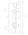
図1は、工作機械の主軸装置の一例を示す。この主軸装置1では、ハウジング2内に主軸3が、軸方向に2列配置される軸受(アンギュラ軸受)4,4によって回転可能に保持されている。主軸3の軸方向で軸受4,4の前後及び軸受4,4の間には、内輪4aに当接する間座5,5,5が設けられている。軸受4,4及び間座5,5,5は、主軸3に軸方向の後方(図1の右側)からねじ込まれるナット6によって押え込まれて予圧が付与されている。
ここでは、各間座5の材料のポアソン比が、主軸3の材料のポアソン比より小さくなっている。ここでいうポアソン比は、主軸3の軸方向と径方向との歪みの比率である。
Hereinafter, an embodiment of the present invention will be described with reference to the drawings.
Fig. 1 shows an example of a spindle unit of a machine tool. In this spindle unit 1, a
Here, the Poisson's ratio of the material of each
この主軸装置1では、主軸3の材料より各間座5の材料のポアソン比を小さくすることで、主軸3が回転した際の各間座5の収縮を抑制することができる。よって、コスト高とならない容易な方法で軸受4と間座5との間に隙間が生じることを防止できる。
In this spindle device 1, the Poisson's ratio of the material of each
なお、押え部材は、ナットに限らず、焼嵌めリングなどを使用してもよい。
アンギュラ軸受は、2列に限らず、3列以上であってもよい。また、軸受はアンギュラ軸受に限らず、他の軸受も採用できる。種類の異なる軸受を併用してもよい。
間座は、主軸の軸方向で軸受と主軸との間、軸受間、軸受と押え部材との間の全てに配置される必要はなく、それらのうちの何れかに配置してもよい。
The pressing member is not limited to a nut, and a shrink-fit ring or the like may be used.
The angular bearing is not limited to two rows, but may be three or more rows. The bearing is not limited to the angular bearing, but other bearings may be used. Different types of bearings may be used in combination.
The spacers do not need to be disposed in the axial direction of the main shaft between the bearing and the main shaft, between the bearings, and between the bearing and the pressing member, and may be disposed in any of these locations.
1・・主軸装置、2・・ハウジング、3・・主軸、4・・軸受、4a・・内輪、5・・間座、6・・ナット。 1: spindle device, 2: housing, 3: spindle, 4: bearing, 4a: inner ring, 5: spacer, 6: nut.
Claims (1)
前記間座の材料における前記主軸の軸方向と径方向との歪みの比率であるポアソン比が、前記主軸の材料における前記主軸の軸方向と径方向との歪みの比率であるポアソン比より小さいことを特徴とする工作機械の主軸装置。 A spindle device of a machine tool, in which a spindle is held within a housing via one or more angular bearings, and spacers are arranged between an inner ring of the angular bearing and the spindle and /or between the inner rings of the multiple angular bearings in the axial direction of the spindle, and a preload is applied by pressing the inner ring of the angular bearing in the axial direction via the spacers by a pressing member provided on the spindle,
a Poisson's ratio which is a ratio of strain in the axial direction to the radial direction of the spindle in a material of the spacer is smaller than a Poisson's ratio which is a ratio of strain in the axial direction to the radial direction of the spindle in a material of the spindle.
Priority Applications (1)
| Application Number | Priority Date | Filing Date | Title |
|---|---|---|---|
| JP2020120809A JP7561532B2 (en) | 2020-07-14 | 2020-07-14 | Machine tool spindle unit |
Applications Claiming Priority (1)
| Application Number | Priority Date | Filing Date | Title |
|---|---|---|---|
| JP2020120809A JP7561532B2 (en) | 2020-07-14 | 2020-07-14 | Machine tool spindle unit |
Publications (2)
| Publication Number | Publication Date |
|---|---|
| JP2022017942A JP2022017942A (en) | 2022-01-26 |
| JP7561532B2 true JP7561532B2 (en) | 2024-10-04 |
Family
ID=80186090
Family Applications (1)
| Application Number | Title | Priority Date | Filing Date |
|---|---|---|---|
| JP2020120809A Active JP7561532B2 (en) | 2020-07-14 | 2020-07-14 | Machine tool spindle unit |
Country Status (1)
| Country | Link |
|---|---|
| JP (1) | JP7561532B2 (en) |
Citations (5)
| Publication number | Priority date | Publication date | Assignee | Title |
|---|---|---|---|---|
| JP2000292620A (en) | 1999-04-06 | 2000-10-20 | Fujikura Ltd | Temperature compensated optical fiber Bragg grating |
| US6135641A (en) | 1997-10-30 | 2000-10-24 | Honeywell International Inc. | Hybrid duplex bearing assembly having thermal compensation |
| JP2001271997A (en) | 2000-03-24 | 2001-10-05 | Tokyo Gas Co Ltd | Inver membrane tank |
| JP2013170656A (en) | 2012-02-22 | 2013-09-02 | Ntn Corp | Preload adjustment structure and preload adjustment method of bearing device |
| JP2015526670A (en) | 2012-08-23 | 2015-09-10 | アンバー キネティクス, インコーポレイテッドAmber Kinetics, Inc. | Apparatus and method for magnetically removing rotor bearing load |
Family Cites Families (3)
| Publication number | Priority date | Publication date | Assignee | Title |
|---|---|---|---|---|
| JPS61116118A (en) * | 1984-11-09 | 1986-06-03 | Toshiba Mach Co Ltd | Rolling bearing |
| JPH0919805A (en) * | 1995-07-04 | 1997-01-21 | Howa Mach Ltd | Preload adjusting mechanism for spindle bearing of machine tool |
| JP3949801B2 (en) * | 1997-12-16 | 2007-07-25 | 東芝機械株式会社 | Bearing device for machine tool spindle |
-
2020
- 2020-07-14 JP JP2020120809A patent/JP7561532B2/en active Active
Patent Citations (5)
| Publication number | Priority date | Publication date | Assignee | Title |
|---|---|---|---|---|
| US6135641A (en) | 1997-10-30 | 2000-10-24 | Honeywell International Inc. | Hybrid duplex bearing assembly having thermal compensation |
| JP2000292620A (en) | 1999-04-06 | 2000-10-20 | Fujikura Ltd | Temperature compensated optical fiber Bragg grating |
| JP2001271997A (en) | 2000-03-24 | 2001-10-05 | Tokyo Gas Co Ltd | Inver membrane tank |
| JP2013170656A (en) | 2012-02-22 | 2013-09-02 | Ntn Corp | Preload adjustment structure and preload adjustment method of bearing device |
| JP2015526670A (en) | 2012-08-23 | 2015-09-10 | アンバー キネティクス, インコーポレイテッドAmber Kinetics, Inc. | Apparatus and method for magnetically removing rotor bearing load |
Also Published As
| Publication number | Publication date |
|---|---|
| JP2022017942A (en) | 2022-01-26 |
Similar Documents
| Publication | Publication Date | Title |
|---|---|---|
| JP6210485B2 (en) | Bearing mechanism | |
| CN111711307B (en) | Bearing pre-tightening structure of motor and motor with same | |
| JP3658994B2 (en) | Method for manufacturing pre-loaded double row rolling bearing device | |
| JP2013194886A (en) | Bearing device and rotating body | |
| JP5704213B2 (en) | Bearing device | |
| JP3652187B2 (en) | Fluid bearing | |
| JP7561532B2 (en) | Machine tool spindle unit | |
| US5820272A (en) | Bearing structure for a rotating shaft | |
| JP3855304B2 (en) | Cross roller bearing preload adjustment structure | |
| JP5638331B2 (en) | Preload adjustment structure for rolling bearings | |
| JP6565454B2 (en) | Combination ball bearing, spindle device, and machine tool | |
| JPH11239902A (en) | Spindle supporting device for machine tool | |
| JP5218137B2 (en) | Bearing device, rotary table of machine tool, and spindle device | |
| JP5453764B2 (en) | Bearing device and assembly method thereof | |
| JPS60139911A (en) | spindle unit | |
| JP2012117567A (en) | Bearing device | |
| JP2006326695A (en) | Bearing device for main spindle of machine tool | |
| JPH0653323B2 (en) | Preload adjustable spindle unit | |
| JPS60172720A (en) | Preload bearing device | |
| JPH0751904A (en) | Pre-load adjusting device for spindle bearing | |
| JP2816596B2 (en) | Bearing preload device | |
| JPH01135916A (en) | Preload adjustable type spindle unit | |
| JP2014151402A (en) | Bearing structure of wheel spindle | |
| JP5041147B2 (en) | Electric motor | |
| JP2623645B2 (en) | Unit bearing for rotary actuator of magnetic disk drive and fixed position preload method for unit bearing |
Legal Events
| Date | Code | Title | Description |
|---|---|---|---|
| A621 | Written request for application examination |
Free format text: JAPANESE INTERMEDIATE CODE: A621 Effective date: 20230428 |
|
| A977 | Report on retrieval |
Free format text: JAPANESE INTERMEDIATE CODE: A971007 Effective date: 20240126 |
|
| A131 | Notification of reasons for refusal |
Free format text: JAPANESE INTERMEDIATE CODE: A131 Effective date: 20240220 |
|
| A521 | Request for written amendment filed |
Free format text: JAPANESE INTERMEDIATE CODE: A523 Effective date: 20240411 |
|
| A131 | Notification of reasons for refusal |
Free format text: JAPANESE INTERMEDIATE CODE: A131 Effective date: 20240514 |
|
| TRDD | Decision of grant or rejection written | ||
| A01 | Written decision to grant a patent or to grant a registration (utility model) |
Free format text: JAPANESE INTERMEDIATE CODE: A01 Effective date: 20240827 |
|
| A61 | First payment of annual fees (during grant procedure) |
Free format text: JAPANESE INTERMEDIATE CODE: A61 Effective date: 20240924 |
|
| R150 | Certificate of patent or registration of utility model |
Ref document number: 7561532 Country of ref document: JP Free format text: JAPANESE INTERMEDIATE CODE: R150 |